EAST WEST UNIVERSITY
|
|
|
- Merryl Maria Shelton
- 5 years ago
- Views:
Transcription

1 EAST WEST UNIVERSITY INTERNSHIP REPORT ON POWER GENERATION, TRANSMISSION AND PROTECTION SYSTEM EQUIPMENTS OF SIDDHIRGANJ EGCB POWER PLANT By Khondoker Fazle Rabbi SID: Tauhid Anwar Bhuiyan SID: Humam Jahanzeb Momen SID: Submitted to the Department of Electrical and Electronic Engineering, Faculty of Sciences and Engineering East West University in partial fulfillment of the requirements for the degree of Bachelor of Science in Electrical and Electronic Engineering (B.Sc. in EEE) [Spring, 2013]
2 INTERNSHIP REPORT ON POWER GENERATION, TRANSMISSION AND PROTECTION SYSTEM EQUIPMENTS OF SIDDHIRGANJ EGCB POWER PLANT By Khondoker Fazle Rabbi SID: Tauhid Anwar Bhuiyan SID: Humam Jahanzeb Momen SID: Submitted to the Department of Electrical and Electronic Engineering, Faculty of Sciences and Engineering East West University in partial fulfillment of the requirements for the degree of Bachelor of Science in Electrical and Electronic Engineering (B.Sc. in EEE) [Spring, 2013] Approved By Intern Advisor Mariam B. Salim Department Chairperson Dr. Mohammad Mojammel Al Hakim 1
3 Approval Certificate 2
4 Approval Certificate 3
5 Approval Certificate 4
6 Acknowledgement First and foremost, we want to convey our heartfelt gratitude to Almighty Allah for His help in complete our internship successfully. We also want to thank the management of Siddhirganj EGCB Power Station for providing us with the opportunity to accomplish our industrial training. We would like to especially thank Engr. Atiar Rahman, Managing Director (Operations) of Siddhirganj EGCB Power Station for giving us the permission to complete our internship work at the power plant. We would also like to thank Ms. Mariam B Salim, our supervising advisor for her constant support and many suggestions, but also for her patience in those times when we faced several problems. We want to thank all those people who helped to complete our internship report successfully. In this process our special thanks goes to Engr. Md. Saiful Islam (Manager - Electrical) who coordinated our internship program and helped us get acquainted with the other engineers. We are very grateful to Engr. Nandhipan Das (Assistant Manager - Technical), Engr. Nadir Chowdhury (Assistant Manager - Operations), Engr. Siddiqur Rahman (Assistant Manager Operation), Engr. A.K.M Zillur Rahman (Assistant Manager - I&C), Engr. Kazi M.H. Kabir (Manager - Environment & Safety), Engr. Ashis Kumar Biswas (Assistant Manager Technical) and Engr. Md. Yamin Ali (Assistant Manager - Technical) for mentoring us. We would also like to mention the name of Dr. Anisul Haque, former Chairperson and Professor of the Department of Electrical & Electronic Engineering, and Dr. Khairul Alam, former Chairperson and Associate Professor of the Department of Electrical & Electronic Engineering, and Dr. Mohammad Mojammel Al Hakim, Chairperson and Associate Professor of the Department of Electrical & Electronic Engineering for being so kind during the period of our internship. We are also grateful to all our teachers for their cooperation and encouragement throughout our whole academic life at East West University. 5
7 Executive Summary We did our internship at Siddhirganj EGCB Power Plant, located on the bank of the river Shitalakha, within the Siddhirganj Power Station premises at Siddhirganj, Narayanganj from 12th of August to the 8th of September. This internship report is the result of those 15 days. The EGCB Siddhirganj Power Station is a newly commissioned power generating plant. It has two generating units, both gas fired, with a peaking capacity of 240MW. Our duration of stay was divided into four sections: generation, instrumentation and control (I & C), mechanical, and electrical. In all of these sections, we were demonstrated how these systems work and what protective measures are taken for them. During our internship, we learned about how electricity is generated, operation of the plant, major equipments like generators, transformers, and switchgear equipments required for distribution of electricity and protection of the plant. We got to learn the importance of protection and switch gear system for the plant and how they work. In the end, our whole internship was the combination of our theoretical and practical knowledge. Protection and controlling of the equipments of the power station is a very important and complicated task. With the help of the plant engineers, we observed the control room operations, and protective equipments such as relays, circuit breakers, lightning arrestors, current transformers, potential transformers, etc. very closely and understood the functions and controlling system of those equipments. All the required information and knowledge was provided to us in a clear way by our mentors at the plant. 6
8 Training Schedule The following table contains our training schedule at EGCB Siddhirganj Power Station. Our internship started on 12th of August 2012 and ended on 8th of September Date Division Time Instructor Electrical 9am to 4pm Engr. Nandhipan Das Asst. Manager (Technical) Control Unit 9am to 4pm Engr. Nadir Chowdhury Asst. Manager (Operation) Engr. Siddiqur Rahman Asst. Manager (Operation) Operation 9am to 4pm Engr. A.K.M Zillur Rahman Asst. Manager (I&C) Fire Safety Training 9am to 4pm Engr. K.M.H Kabir Manager (Environment & Safety) Electrical 9am to 4pm Engr. Nandhipan Das Asst. Manager (Technical) Engr. Ashis Kumar Biswas Asst. Manager (Technical) Mechanical 9am to 4pm Engr. Yamin Ali Asst. Manager (Technical) 7
9 Electrical 9am to 4pm Engr. Nandhipan Das Asst. Manager (Technical) Engr. Ashis Kumar Biswas Asst. Manager (Technical) Electrical 9am to 4pm Engr. Saiful Islam Manager (Electrical) Mechanical 9am to 4pm Engr. Yamin Ali Asst. Manager (Technical) 8
10 TABLE OF CONTENTS Table of Contents Approval Certificate...2 Approval Certificate...3 Approval Certificate...4 Acknowledgement...5 Executive Summary...6 Training Schedule...7 List of Figures...13 List of Tables...14 Chapter 1 Introduction Company Profile Background of the MW Peaking Power Plant Construction of the Plant Gas Availability and Usage Future Projects of EGCB Objective of the Internship Scope and Methodology...17 Chapter 2 Mechanical Components Introduction Mechanical components Compressors Compressor Blade Combustion System Combustion Chamber Spark Plugs Ultraviolet Flame Detectors Crossfire Tubes
11 Fuel Nozzle Turbine Turbine Buckets Nozzles Exhaust Frame Bearings Generator Gas Booster Compressor Plant Air and Instrument Air Water Treatment Plant Modes of Operation Exhaust System...26 Chapter 3 Power Plant Electrical Components Introduction Transformer Power Transformer Instrument Transformer Current Transformer (CT) Potential Transformer (PT) AC and DC Auxiliary System AC Auxiliary System Unit Auxiliary System Station Auxiliary System DC Auxiliary System Circuit Breaker Air Circuit Breaker SF6 (Sulphur Hexafluoride) Circuit Breaker Vacuum Circuit Breaker Bus Bar...36 Chapter 4 Testing and Cooling System Introduction
12 4.2 Oil Test Transformer Oil Testing Procedure Cooling System Air Cooling Water Cooling...40 Chapter 5 Protection Introduction Generator Protection Over-Current Protection Over-Voltage Protection Frequency Protection Frequency Relay Rotor Earth Fault Protection Under Excitation (Loss of field) Protection Transformer Protection Differential Protection Protective Relay Over-current Relay Distance Relay Buchholz Relay Lightning Arrester Isolator Relay Electromagnetic Relay Fire Safety Measures...47 Chapter 6 Control Rooms Introduction Central Control Room Secondary Control Room Switch Gear Control Room
13 Chapter 7 Conclusion Our Achievements Problems Faced Recommendations Discussion...52 Appendix...53 References...55 Daily Activity Report
14 List of Figures Figure 2.1: Compressor Rotor...19 Figure 2.2: Combustion Liner...19 Figure 2.3: Combustion Chamber...20 Figure 2.4: Crossfire Tubes...21 Figure 2.5: Dry Low NOx Combustor...26 Figure 3.1: Ideal Transformer as a Circuit Element...28 Figure 3.2: One of the 11/132 KV power transformer used in EGCB Power Plant...28 Figure 3.3: Current Transformer at the EGCB power plant...29 Figure 3.4: Potential Transformer at the EGCB power plant...30 Figure 3.5: Unit Auxiliary Transformer...31 Figure 3.6: Station Auxiliary Transformer used at the EGCB Power Plant...32 Figure 3.7: The DC Auxiliary System storage facility at the EGCB Power Plant...33 Figure 3.8: Ni-Cd Battery used for the DC Auxiliary System at the EGCB Power Plant...33 Figure 3.9: Air Circuit Breaker used at the EGCB Power Plant...34 Figure 3.10: SF6 Circuit Breaker used at the EGCB Power Plant...34 Figure 3.11: Vacuum Circuit Breaker used at the EGCB Power Plant...35 Figure 3.12: Single Line Diagram of 2x120 MW Power Plant at EGCB showing Double Bus Bars...36 Figure 4.1: Voltage Breakdown during Transformer Oil Testing...38 Figure 5.1: List of Fittings (showing different protections) from 11/132 KV Transformer used at the EGCB Power Plant...43 Figure 5.2: Buchholz Relay used at the EGCB Power Plant...45 Figure 5.3: Lightning Arrester used at the EGCB Power Plant...45 Figure 5.4: Isolators used at EGCB Power Plant...46 Figure 5.5: CO2 cylinders for fire safety at the EGCB power plant...47 Figure 6.1: Screenshot of the Vibration Protection System interface at the Central Control Room
15 Figure 6.2: One Side of the Manual Control Room at EGCB Power Plant...50 List of Tables Table 2.1: List of Some Bearings...22 Table 2.2: Ratings of Generator used in EGCB Power Plant...24 Table 3.1: Salient features of the Power Transformer at the EGCB power plant...29 Table 3.2: Salient features of the Unit Auxiliary Transformer at the EGCB power plant...31 Table 3.3: Salient features of the Station Auxiliary Transformer at the EGCB power plant..32 Table 3.4: Specifications of SF6 circuit breaker used at the EGCB Power Plant...35 Table 3.5: Specifications of Vacuum Circuit Breaker used at the EGCB Power Plant
16 Chapter 1 Introduction The power generation sector is one of the most important sectors of our country. All the other sectors are directly or indirectly dependent on it. As a result industrial and overall economic growth is dependent on the power generation sector. But our power generation sector has been marred by many problems. The biggest problem is the inadequate generation of electricity. Day by day the demand for electricity in our country is increasing but the generation of power is not increasing at the same rate. Previously the sole responsibility of generation, transmission and distribution of electricity lied on the shoulders of Bangladesh Power Development Board (BPDB). But over the years, by making the BPDB a mother company, the government of Bangladesh has created several separate publicly owned entities under the BPDB for generation, transmission and distribution of electricity, thus relieving BPDB of the responsibilities of generation, transmission and distribution of electricity. Electricity Generation Company of Bangladesh (EGCB) is one such publicly owned entity for generating electricity [1]. It was a great opportunity to complete our internship at the EGCB Power Plant located inside the Siddhirganj Power Station premises. It is one of the most advanced power plants in the country. This plant has been adding electricity to the national grid since During our internship, we closely observed the generation, operation, switching station, and instrumentation and control sections of the plant. This chapter gives the overall idea about EGCB as a company, including the background, present capabilities, and future plan. 1.1 Company Profile The Electricity Generation Company of Bangladesh (EGCB) Ltd is an enterprise of the Bangladesh Power Development Board (BPDB). It came into existence on the 16 th of February, It was previously known as the Meghnaghat Power Company (MPC) Ltd. EGCB plans to become a leading electricity generation company across the country. The company's major share is held by BPDB [1]. 15
17 1.2 Background of the MW Peaking Power Plant Construction of the Plant The construction of the EGCB MW Peaking Power Plant was completed on the bank of the river Shitalakha within the Siddhirganj Power Station premises. It was funded by the Asian Development Bank. Bharat Heavy Electricals Limited (BHEL) was the equipment procuring contractor (EPC) for this project. The first generating unit was put on test run on the 20th of November 2009 and it was inaugurated by the Honorable Prime Minister Sheikh Hasina on the 14th of February The second generating unit was put on test run on the 26th of May The second generating unit was taken over from the EPC contractor on the 14th of October Combined generation and distribution from both units was effective from the 5th of February 2012 [1] Gas Availability and Usage The gas to the power plant is supplied by Titas. Unfortunately, due to the presence of Adamjee Export Processing Zone (AEPZ) nearby, the plant does not receive the required gas pressure for optimum operation. The AEPZ houses many export oriented industries which require gas supplied by Titas for manufacturing. As a result the EGCB Power Plant operates below its capacity most of the time. Sometimes the gas pressure becomes too low for operation. Therefore, during those times there is no generation of electricity at the plant [1]. 1.3 Future Projects of EGCB EGCB has undertaken two new projects to add to its portfolio. Construction of both projects is now underway. One is the 335 MW Combined Cycle Power Plant near the Siddhirganj Power Station premises and the other is the Haripur 360 MW Combined Cycle Power Plant at Haripur. Both projects were approved by the Government of Bangladesh under its grand plan of achieving zero load-shedding by The construction of the EGCB 335 MW Combined Cycle Power Plant is to be completed by whereas the Haripur 360 MW Combined Cycle Power Plant is expected to be completed by July 2013 [1]. 1.4 Objective of the Internship The main goal of this internship was to gather practical knowledge and experience about power station. In this internship report, we have focused on the generation process, protection strategy and maintenance of individual sections, and the control unit of EGCB Siddhirganj 16
18 Power Plant which we saw during our internship period. We have tried to give a complete overview of our experience at EGCB in this report. 1.5 Scope and Methodology This report focuses on the total process of power generation, including water resource management, boiler management, generator, open cycle power plant and switching station. This report also mentions the protection and maintenance of generator, boiler, and turbine. The instrumentation and control section have also been discussed here. During our internship period, our mentors showed us various equipments and sections of the power station. This entire report was written based on what we learned in relative courses, our experience at the EGCB Power Plant, lectures and documents provided by the EGCB mentors, and relative books. 17
19 Chapter 2 Mechanical Components 2.1 Introduction The mechanical components of the power plant were shown to us by Engr. Yamin Ali, Asst. Manager (Technical) at the power plant. This chapter includes information we learned about the mechanical components used in EGCB Power Plant, the modes of operation and the exhaust system. 2.2 Mechanical components The mechanical components are the main features for the generation of electricity. There are various types of components used in power generation. The mechanical components that we were taught about, and in some cases were shown, are given below: 1. Compressor, 2. Combustion System, 3. Turbine, 4. Generator, 5. Gas Booster Compressor, 6. Plant Air and Instrument Air, 7. Water Treatment Plant Compressors The compressor is used to compress the natural air. The compressed air is used in the combustion chamber to ignite the gas. The compressor section consists of compressor rotor and compressor stator. There are 17 stages of compressor blades consisting of inlet and outlet guide valves. In the compressor, air is compressed in stages by a series of alternate rotating (rotor) and stationary (stator) blades. Compressed air is extracted from the compressor for turbine cooling, for bearing sealing, and for compressor pulsation control during startup and shutdown [4]. 18

![Stages 1 through 8 out of 17 stages of rotor blades are mounted by axial dovetails into blade ring segments [4].](/docs-images/83/88351489/images/20-1.jpg "During operation of the gas turbine, air is extracted from various stages of the axial flow compressor to: 1. Cool the turbine parts subject to high operating temperatures. 2.")
20 Compressor Blade The compressor rotor blades are airfoil shaped and are designed to compress air efficiently at high blade tip velocities. The forged blades are attached to their wheels by axial dovetail connections. The dovetail is accurately machined to maintain each blade in the desired location on the wheel. Stages 1 through 8 out of 17 stages of rotor blades are mounted by axial dovetails into blade ring segments [4]. During operation of the gas turbine, air is extracted from various stages of the axial flow compressor to: 1. Cool the turbine parts subject to high operating temperatures. 2. Seal the turbine bearings. 3. Provide an operating air supply for air-operated valves. 4. Fuel nozzle atomizing air (if applicable). 17th stage compressor rotor blade Aft stub shaft Figure 2.1: Compressor Rotor [3] Combustion System The combustion system consists of combustion chamber, spark plugs, ultraviolet flame detector, crossfire tubes, fuel nozzle, etc. When the fuel burns, a huge amount of heat is produced. This is used to drive the turbine. Fuel is supplied to each combustion chamber through a nozzle which is designed to disperse and mix the fuel with the proper amount of combustion air within the liner. Figure 2.2: Combustion Liner [4] 19

21 Combustion Chamber We have seen 14 combustion chambers and each of the combustion chambers are connected internally. Air discharged from the compressor flows to the combustion chamber through nozzles and enters into the combustion chamber reaction zone through the liner cap holes. The additional air is mixed with the combustion gases and enters into the reaction zone. The 14 chambers are identical with the exception of those fitted with spark plugs or flame detectors [4]. Location of spark plugs Location of flame Location of flame detectors detectors Figure 2.3: Combustion Chamber [3] Spark Plugs The combustion is initiated by means of discharge from two high voltage electrode spark plugs. Spark plugs are present at combustion chamber number 13 and 14. At the time of ignition, one or both sparks of these plugs ignite a chamber. The remaining chambers are ignited by crossfire through the tubes that interconnect the reaction zones of the remaining chambers. As rotor speeds up and air flow increases, the spark plugs and the high voltage electrodes are withdrawn from the combustion chamber [4] Ultraviolet Flame Detectors It is necessary to know the absence or presence of flame inside the combustion system and to send the signal to the control room. There are four flame detectors in four different combustion chambers of the EGCB power plant. These chambers are chamber number 4,5,10 and 11. The control system continuously monitors the presence or absence of flame. The failure to fire or loss of flame is indicated on the control panel [4] Crossfire Tubes The 14 combustion chambers are interconnected by means of crossfire tubes. These crossfire tubes propagate the flame from one combustion chamber to other [4]. 20
![Crossfire tube Figure 2.4: Crossfire Tubes [3] 2.2.2.5 Fuel Nozzle The combustion chamber also consists of fuel nozzle.](/docs-images/83/88351489/images/22-0.jpg "Gaseous fuel is entered directly into each combustion chamber through metering holes located at the inner edge of the chamber.")
22 Crossfire tube Figure 2.4: Crossfire Tubes [3] Fuel Nozzle The combustion chamber also consists of fuel nozzle. Gaseous fuel is entered directly into each combustion chamber through metering holes located at the inner edge of the chamber. Both gas and oil fuel may be burned simultaneously in a dual-fuel turbine configuration where the percentage of each fuel is determined by the operator within the control system limits [4] Turbine The turbine has three sections. These are turbine rotor, stator and buckets. Here the energy from the high pressurized gas which is produced by the compressor and the combustion section is converted into mechanical energy [4]. We did not see the turbine rotor and stator. The parts which we have learnt from our mentor are discussed below Turbine Buckets There are three stages in turbine buckets. The turbine buckets increase in size from the first stage to the third stage. At every stage of energy conversion a high pressure is reduced, So that a large annular area is required to accommodate the gas flow. The hot gases extracted from the first stage nozzles first fall into the first stage rotating buckets of the turbine rotor. Buckets are placed in a manner that they can be set out easily for maintenance [4]. 21
23 Nozzles There are three stages of nozzles in the turbine stator section. These nozzles direct the high velocity flow of expanded hot combustion gas against the turbine bucket which causes the rotor to rotate. As these nozzles operate in the hot combustion gas flow, they are subjected to thermal stresses in addition to gas pressure loadings Exhaust Frame The exhaust frame assembly consists of exhaust frame and diffuser. The exhaust frame is connected by bolts with the turbine shell. The frame consists of two cylinders, one inner cylinder and one outer cylinder. They are interconnected by bolts. The inner gas path surfaces of the two cylinders are attached to the inner and outer diffusers. The diffusers spread the heat across the surface or area. The exhaust diffuser is located between the outer and inner cylinders. Gases exhausted from the third turbine stage enter the diffuser where the velocity is reduced by diffusion and pressure is recovered. The exhaust frame is cooled by a portion of cooling air supplied by off-base motor driven blowers then enters the turbine shell after cooling the outer frame and the radial support struts [4] Bearings The PG 9171E gas turbine contains three main journal bearings used to support the rotor. Rotor to stator axial position is controlled by thrust bearing. This bearing assembles are located in three bearing house: one at inlet casing, one in the compressor discharge and one in the exhaust frame. These main bearings are pressure lubricated by oil supplied from the main lubricating oil system. The oil flows through branch lines to an inlet in each bearing housing [4]. Table 2.1: List of Some Bearings Housing Class Type 1 Journal Elliptical 1 Loaded Thrust Self -Aligned 1 Unloaded Thrust Tilting-Pod 2 Journal Elliptical 3 Journal Elliptical 22
24 2.2.4 Generator A generator is an electrical device which converts mechanical energy into electrical energy. The generator consists of the following components: 1. Stator, 2. Frame, 3. Stator core, 4. Stator winding, 5. Stator end covers, 6. Rotor, 7. Rotor windings, 8. Rotor retaining rings, 9. Field connections, 10. Bearings, 11. Foundation frame, 12. Air filters, 13. Enclosure, 14. Generator Auxiliary Compartment, etc. In a synchronous generator, a dc current is applied to the rotor winding, which produces a rotor magnetic field. The rotor of the generator is then turned by a prime mover, producing a rotating magnetic field within the machine. This rotating magnetic field induces a three phase set of voltages within the stator windings of the generator. At EGCB MW Peaking Power Plant, brushless exciters are used to supply the dc field current to the machine. A brushless exciter is a small ac generator with its field circuit mounted on the stator and its armature circuit mounted on the rotor shaft. The three phase output of the exciter generator is rectified to direct current by a three phase rectifier circuit also mounted on the shaft of the generator, and is then fed into the main dc field circuit. By controlling the small dc field of the exciter generator, it is possible to adjust the field current on the main machine without slip rings and brushes. At the EGCB MW Peaking Power Plant, the dc field is controlled by an Automatic Voltage Regulator (AVR). Thyristors are used for this purpose. At a certain firing angle the thyristors are fired. The firing angle is determined by considering certain parameters [4]. 23
25 The ratings of the generator used in EGCB are given below: Table 2.2: Ratings of Generator used in EGCB Power Plant Manufactured by Jhansi, BHEL India KVA KW PF(lag) 0.80 Frequency 50 HZ RPM 3000 Phase 3(AC) Stator voltage 11000V Stator current 7125A Rotor voltage 370V Rotor current 817A Gas Booster Compressor Gas booster compressor (GBC) is an important part of the EGCB MW Peaking Power Plant. It is used to boost up the speed of the gas. The gas supplied from Titas is not fully pressurized enough for combustion. There are a lot of pneumatic valves in this plant. Some get air from bottom and some get air from top. The ones which get air from the top are called air to open and the ones which get air from the bottom are called air to close. Gas Booster Compressor (GBC) compressor has six stages. It is a centrifugal compressor. It has a suction line and a discharge line. The discharge gas has high temperature and pressure. Discharge temperature is 135 C and pressure is 25 kg. Gas cooler is used to reduce the temperature of the gas. When the turbine is not started, the discharge gas is again fed into the suction line through an anti-surge valve. Anti-surge valve is used to reduce the pressure of the feeder gas [5] Plant Air and Instrument Air An air compressor is used to produce instrument air, plant air, and nitrogen. Carbon molecular fid (CMF) is used to absorb the carbon related material. Oxygen is also absorbed by CMF. Instrument air is used in different types of pneumatic valve and in journal bearing. Lube (lubricating) oil is used for the operation of journal bearing. As it is a mechanical contact, it cannot be 100% leakage free. So the lube oil can leak out from the bearing. To stop the leaking, instrument air is used as a filling to pressurize the lube oil. This filling is used 24
26 only at GBC. Since lube oil and instrument air can react with each other, nitrogen is used as a barrier to hinder the reaction. Nitrogen is also used inside different pipes when the operation at the plant remains turned off for a long time. This is used to stop the corrosion of the pipe [5] Water Treatment Plant Water treatment plant is necessary to make it useful for the plant. Here water is used for cooling. Mineralized water is not directly used in the plant. It is full of different minerals, anions and cations. If the mineralized water is used, it will react with metal, which is not desired. At the water treatment plant, the water from the river Shitalakhya is treated. First the anions and cations are removed and then make the water is de-mineralized by reverse osmosis process. Reverse osmosis is a process that various industry uses to clean water. Different types of motor and pumps are used in this process. The driving force of the reverse osmosis process is applied pressure [5]. 2.3 Modes of Operation The combustors of EGCB Power Plant control the emission of nitrogen oxide. To maintain this, the combustor operates at three different modes [5]. These modes are 1. Primary, 2. Lean lean, and 3. Premix steady state. The combustion chamber has two regions, primary and secondary. There are also primary and secondary nozzle from which the fuel enters into the combustors. To operate at the above three modes, the fuel and flame position changes inside the combustors [4]. A brief explanation of these modes is given below: Primary: In this mode, fuel is present only at the primary nozzle and flame is present in the primary stage only. This mode of operation is used to ignite, accelerate, and operate the machine over low to mid-loads, up to a pre-selected combustion reference temperature [5]. Lean lean: In this mode, fuel is present in both the primary and secondary nozzles. Flame is present in both the primary and secondary stage. This mode of operation is used for intermediate loads between two pre-selected combustion reference temperatures [5]. 25
27 Premix steady state: In this mode, fuel is present in both primary and secondary nozzles. Flame is present in the secondary stage only. This mode of operation is achieved at and near the combustion reference temperature design point. Optimum emissions are generated in premix mode. The flow of fuel to the combustors for different modes of operation is controlled by 1 speed/stop ratio valve (SRV) and three gas controlling valves (GCV) [5]. Figure 2.5: Dry Low NOx Combustor [3] 2.4 Exhaust System Exhaust systems are necessary to guide the exhaust fuel gases of gas turbine into the atmosphere. The use of exhaust systems behind the gas turbine is mandatory as the exhaust fuel gases contain temperatures between C. Gas turbine exhaust systems must perform three functions: reduce noise to the atmosphere, vent hot gases away from personnel, minimize backpressure to gas turbines [4]. 26
28 Chapter 3 Power Plant Electrical Components 3.1 Introduction In this part of our industrial training, Engr. Nandhipan Das and Engr. Ashis Kumar, both Assistant Managers at the power plant were our mentors. There are many electrical components in the EGCB power plant. Among the most important electrical components are: Transformers, Bus bar, and Circuit breakers. Transformers are used to step up or step down the voltages for transmission of power. Circuit breakers are used to provide different types of protection for the different equipments at the power station. The use of transformers, circuit breakers, bus bars and their operating mechanism are discussed in this chapter. 3.2 Transformer A transformer is an electrical device that takes electricity at one voltage and changes it into electricity of a different voltage. This occurs by inductive coupling which is related to the magnetic flux changing in the primary winding of the transformer. This results in changing magnetic flux in the secondary winding that induces a varying voltage secondary winding. At this point a load is connected in the secondary winding that causes current flow in the secondary winding and thus transformation of electricity [9]. An ideal transformer has two windings, primary and secondary. Primary winding voltage is denoted as (Vp) and secondary winding induced voltage (Vs). The ratio of the primary winding voltage to secondary winding induced voltage is equal to the ratio of number of turns in the primary winding (Np) to number of turns in the secondary winding (Ns). At EGCB power plant, we saw both power and instrument transformers. There was a switchyard for each unit where the instrument transformers were present. We have discussed about them below. 27
![Figure 3.1: Ideal Transformer as a Circuit Element [10] 3.2.1 Power Transformer Power transformers are used to step-up or step-down voltages for distribution.](/docs-images/83/88351489/images/29-1.jpg "At EGCB power plant there are six power transformers, three for each unit. There are two 11/132 KV, two 11/6.6KV, two 6.6/0.4KV power transformers.")
29 Figure 3.1: Ideal Transformer as a Circuit Element [10] Power Transformer Power transformers are used to step-up or step-down voltages for distribution. At EGCB power plant there are six power transformers, three for each unit. There are two 11/132 KV, two 11/6.6KV, two 6.6/0.4KV power transformers. An 11/132 KV transformer means that the input into the transformer is 11 KV and the transformer provides an output of 132 kv. Hence it is a step-up transformer and is basically used to supply the generated electricity (at 11 KV) to the substation (at 132 KV). The other transformers are step-down transformers and are used to get the desired voltage level for different equipments used in the plant. This means that at the plant there are different equipments that require either 6.6 KV or 0.4 KV to operate. These step-down transformers provide the 6.6 KV or 0.4 KV voltage levels to the bus bars. Figure 3.2: One of the 11/132 KV power transformer used in EGCB Power Plant [2] 28
 Type of Cooling Oil Forced Air Forced (OFAF) Line Current")
30 The salient features of the power transformer used at the EGCB power plant are given below: Table 3.1: Salient features of the Power Transformer at the EGCB power plant Manufactured By Jhansi, BHEL India, 170 MVA Voltage 11/132 KV (step up) Type of Cooling Oil Forced Air Forced (OFAF) Line Current LV Side: Amperes HV Side: Amperes Instrument Transformer Instrument transformers are used for accurate and reliable current and voltage measurements for secondary equipments such as meters, protection relays and other devices measurements which provide safe and efficient operation of transmission networks. Instrument transformers include: Current Transformer (CT), and Potential Transformer (PT). The functions of CT and PT are discussed below Current Transformer (CT) A current transformer is used in high voltage circuits where it is not possible to measure current directly. CT steps down high current to very low current that can be handled easily and thus can be read. Its secondary is connected to an ammeter of very small capacity (usually 5 A) but its scale is calibrated according to actual values. A current transformer is selected according to the ratio of maximum load current and required current. For EGCB power plant, the CT ratio is 800/1 for 132 KV line current. Figure 3.3: Current Transformer at the EGCB power plant [2] 29

31 Potential Transformer (PT) Potential transformers have a large number of primary turns and a small number of secondary turns and may be either single phase or three phase units. For EGCB the PT ratio is 1200/1 for 132 KV line. This means that the PT converts the 132 KV voltage into 110 V voltage, measures the voltage with a meter and applies a user programmed multiplier (1200) to this number (110 V) to calculate the original voltage. The output seen by the user is after the multiplication. Figure 3.4: Potential Transformer at the EGCB power plant [2] AC and DC Auxiliary System Auxiliary system is used to power up the power plant equipment s and provide backup when AC power supply fails. There are two types of auxiliary system in EGCB. They are: 1. AC auxiliary system, and 2. DC auxiliary system AC Auxiliary System AC auxiliary system is used to operate the internal equipment s within the power plant. There are two types of AC auxiliary system in EGCB. They are: i. Unit auxiliary system, and ii. Station auxiliary system Unit Auxiliary System In order to start the AC generator present in the power plant, the auxiliaries of this unit need to be started. Power required to start these auxiliary drives is derived from a step down 30
 and the low voltage (LV) side voltage is stepped down to 6.6 KV. Figure 3.")
32 transformer connected to the high voltage (HV) bus and this transformer is called unit auxiliary transformer. The HV side transformer voltage corresponds to the voltage of the generating unit (11 KV) and the low voltage (LV) side voltage is stepped down to 6.6 KV. Figure 3.5: Unit Auxiliary Transformer [2] The salient features of the Unit Auxiliary Transformer at the EGCB power plant are given below: Table 3.2: Salient features of the Unit Auxiliary Transformer at the EGCB power plant Manufactured By Jhansi, BHEL India, 12.5 MVA Voltage 11/6.6 KV (step down) Type of Cooling Oil Natural Air Forced (ONAF) Line Current LV Side: Amperes HV Side: Amperes Station Auxiliary System The station auxiliary transformer is used to step down voltage from 6.6 KV to 440 V. The rating for this transformer corresponds to the rating of the auxiliary load it should be bearing. The HV side transformer voltage corresponds to the voltage of the unit auxiliary transformer (6.6 KV) and the LV side voltage is stepped down to 0.44 KV. 31
![Figure 3.6: Station Auxiliary Transformer used at the EGCB Power Plant [2] The salient features of the Station Auxiliary Transformer at the EGCB power plant are given below: Table 3.](/docs-images/83/88351489/images/33-0.jpg "3: Salient features of the Station Auxiliary Transformer at the EGCB power plant Manufactured By Jhansi, BHEL India, 2.5 MVA Voltage 6.6/0.")
33 Figure 3.6: Station Auxiliary Transformer used at the EGCB Power Plant [2] The salient features of the Station Auxiliary Transformer at the EGCB power plant are given below: Table 3.3: Salient features of the Station Auxiliary Transformer at the EGCB power plant Manufactured By Jhansi, BHEL India, 2.5 MVA Voltage 6.6/0.440 KV (step down) Type of Cooling Oil Natural Air Natural (ONAN) Line Current LV Side: Amperes HV Side: Amperes DC Auxiliary System DC auxiliary power systems are used to maintain or manage systems during loss of power in the main line. In general, a DC auxiliary power system comprises of a battery and charger, both of which are connected to the DC distribution bus. The capacity, voltage and autonomy (region) of the auxiliary system varies depending on its operating purpose. At EGCB the batteries are of Nickel Cadmium (Ni-Cd) and the equipments that need DC supply is: All Field Instruments (24 V DC), Circuit breakers module control power supply (110 V DC), GT emergency drive panel (125V DC), Mark VI Control System for GT (125 V DC), and All GT solenoids (125 V DC). 32
![Figure 3.7: The DC Auxiliary System storage facility at the EGCB Power Plant [2] Figure 3.8: Ni-Cd Battery used for the DC Auxiliary System at the EGCB Power Plant [2] 3.](/docs-images/83/88351489/images/34-0.jpg "3 Circuit Breaker A circuit breaker (CB) is an automatic switch that stops the flow of electric current in a suddenly overloaded or otherwise abnormally stressed electric circuit.")

34 Figure 3.7: The DC Auxiliary System storage facility at the EGCB Power Plant [2] Figure 3.8: Ni-Cd Battery used for the DC Auxiliary System at the EGCB Power Plant [2] 3.3 Circuit Breaker A circuit breaker (CB) is an automatic switch that stops the flow of electric current in a suddenly overloaded or otherwise abnormally stressed electric circuit. During abnormal conditions, when excessive current develops, a circuit breaker opens to protect equipment and surroundings from possible damage due to excess current. A CB does not need to be replaced like a fuse after each operation. It can be reset either manually or automatically to its normal operating condition [11]. There are different types of circuit breakers in EGCB. They are: Air Blast Circuit Breaker (ABCB), Air Break Circuit Breaker (ACB), SF6Circuit Breaker, Vacuum Circuit Breaker (VCB), Miniature Circuit Breaker (MCB), and Molded Case Circuit Breaker (MCCB) Air Circuit Breaker The Air Circuit Breaker (ACB) creates an arc voltage in excess of the supply voltage. An Arc is an electric discharge between two electrodes. Arc voltage is defined as the minimum voltage required in maintaining the arc. In EGCB there are two types of ACB: 33
: Low voltage circuit breaker used for the protection of the 400 V line in EGCB. Figure 3.9: Air Circuit Breaker used at the EGCB Power Plant [2] 3.")

35 1. Air Blast Circuit Breaker (ABCB): Low voltage circuit breaker used for the protection of the 230 V line in EGCB. 2. Air Break Circuit Breaker (ACB): Low voltage circuit breaker used for the protection of the 400 V line in EGCB. Figure 3.9: Air Circuit Breaker used at the EGCB Power Plant [2] SF6 (Sulphur Hexafluoride) Circuit Breaker It is the circuit breaker in which the current carrying contacts are operated by Sulphur Hexafluoride or SF6 gas. It is used in high voltage protection. At EGCB, the SF6 breaker is used in protection of 11 KV line. Due to its high dielectric strength and high cooling effect, SF6 gas is approximately 100 times more effective as an arc quenching media than air. Due to this unique property of SF6 gas, this circuit breaker is used in complete range of medium voltage and high voltage electrical power system. Figure 3.10: SF6 Circuit Breaker used at the EGCB Power Plant [2] 34

36 The specifications of the SF6 circuit breaker used at the EGCB power plant are given below: Table 3.4: Specifications of SF6 circuit breaker used at the EGCB Power Plant Model HECS-100M Serial Number HA Rated Frequency 50Hz Rated Operating SF6 Density 40.7 kg/m3 Rated Control Voltage for Closing and 125VDC Trapping Coils Rated Voltage for Pump Motor Drive 125VDC Closing and Trapping Current 3A Current of the Pump Motor Drive 6A Vacuum Circuit Breaker Vacuum Circuit Breaker (VCB) is an electrical circuit breaker in which the contacts that perform switching and interrupting functions are enclosed in a vacuum. The VCB has very reliable current interruption technology and it requires minimum maintenance compared to other circuit breaker technologies. We saw indoor type VCB at EGCB power plant. Figure 3.11: Vacuum Circuit Breaker used at the EGCB Power Plant [2] 35
37 The specifications of the Vacuum Circuit Breaker used at the EGCB power plant are given below: Table 3.5: Specifications of Vacuum Circuit Breaker used at the EGCB Power Plant Manufactures name and Collaborator M/S BHEEL, BHOPAL Type Designator VM 12 (820 mm) Number of Poles 3 Class Indoor Rated Voltage 3.6/7.2/12 KV Rated Frequency 50Hz Rated Normal Current 630/800/1250/1600/2000/2500/3150 A Changing Motor 230VAC/220VDC Auxiliary Supply for Closing Trapping Coil 24/30/110/220 V DC 3.4 Bus Bar Figure 3.12: Single Line Diagram of 2x120 MW Power Plant at EGCB showing Double Bus Bars [3] 36
38 Bus bars are very important in an electrical substation. In electrical power distribution, a bus bar is a strip or bar of metal (copper, brass or aluminum) that conducts electricity within a switchboard, distribution board, substation, battery bank or other electrical apparatus. The bars may be exposed or enclosed. There are individual bus bars in EGCB for 11/6.6 KV and 6.6/0.44 KV. In EGCB, we have seen double bus bar and reserved bus bar diagram. The bus bar starts from the two generators G1 and G2. There are different bus bars for 11/6.6 KV and 6.6/0.44 KV. There is reserved bus bar also. The main purpose of using double bus bar arrangement is to increase the flexibility of system so in case of power failure the reserved bus bar can be used. 37

39 Chapter 4 Testing and Cooling System 4.1 Introduction The testing and cooling system of the power plant were shown to us by Engr. Ashis Kumar Biswas, Asst. Manager (Technical) at the power plant. This chapter includes the testing and cooling system used in EGCB MW Peaking Power Plant. Transformer oil testing was done during our internship period. Two different types of cooling system are present in EGCB which was shown and described by our mentor. 4.2 Oil Test The insulation oil of potential transformer and current transformers fulfills the purpose of insulating as well as cooling. Thus, the dielectric quality of transformer oil is a matter of secure operation of a transformer. Since transformer oil deteriorates in its isolation and cooling behavior due to ageing and pollution by dust particles or humidity, the transformer oil must be subject to oil tests on a regular basis. Transformer oil testing sequences and procedures are defined by various international standards. Figure 4.1: Voltage Breakdown during Transformer Oil Testing [2] Periodic execution of transformer oil testing is very important for energy supplying companies, as potential damage to the transformer insulation can be avoided by well timed substitution of the transformer oil. 38
40 4.2.1 Transformer Oil Testing Procedure To assess the insulating property of dielectric transformer oil, a sample of the transformer oil is taken and its breakdown voltage is measured. There are several steps in measuring the dielectric strength of the transformer oil. The steps are given below: 1. First the oil is filled in a vessel of the testing device. There are two electrodes inside the vessel. The distance between the electrodes is 2.5 mm and they are surrounded by the dielectric oil. 2. A test voltage is applied to the electrodes and is continuously increased up to the breakdown voltage. 3. After a certain voltage level, the dielectric strength of the oil breaks down and an electric arc occurs between the two electrodes. 4. When the arc forms, the test voltage automatically gets withdrawn immediately. This immediate withdrawal should be maintained to keep the additional pollution as low as possible. 5. The transformer oil testing device measures and reports the root mean square value of the breakdown voltage. 6. After the first test of transformer oil, the insulation oil is stirred automatically and the test sequence is performed repeatedly. 7. By taking the mean of all the resulting voltage, we get breakdown voltage. The lower the resulting breakdown voltage, the poorer is the quality of the transformer oil. 4.2 Cooling System There are two types of cooling system is present in the EGCB MW Peaking Power Plant. 1. Air cooling system, 2. Water cooling system Air Cooling The cooling and sealing air system provides the necessary air flow from the gas turbine compressor to other parts of the gas turbine rotor and stator to prevent excessive temperature build up in these parts during normal operation. Air from three centrifugal type blowers (1 is 88TK-1 type & 2 are 88TK-2 type) is used to cool the turbine exhaust frame. These two 39
41 motor fans are part of a cooling system. They are situated on a base near the lower part of the gas turbine exhaust system duct. Cooling functions provided by the system are as follows: 1. Cooling of internal turbine parts subjected to high temperature, and 2. Cooling of the turbine outer shell and exhaust frame Water Cooling The cooling water system is a pressurized, closed system, designed to accommodate the heat dissipation requirements of the turbine, the lubrication system, the atomizing air system, the turbine support legs, and the flame detectors. The cooling water system circulates water as a cooling medium to maintain the lubricating oil at acceptable lubrication system temperature levels and to cool several turbine components. Water cooling covers a significant part of the cooling system. Where there is lube (lubricating) oil, the cooling system is water cooling. Every bearing and the pipe of lube oil is water cooled. The pipe of lube oil goes through the water pipe. Thus water absorbs the heat of the lube oil and the water becomes hot. The hot water is then carried out and cooled by air. The air is supplied by six large electric fans at every water stock. These fans are driven by ac and dc motor. The dc motor is for redundant operation. If any fault or accident occurs and the ac motor stops working, then the dc motor is used. 40
42 Chapter 5 Protection 5.1 Introduction The purpose of a protection system is to disconnect the faulty parts of the power system in conjunction with the circuit breakers. This is necessary in order to: protect the primary equipment s against unnecessary damage, save people in the vicinity of the electrical plant from injuries, and enable continued service in the undamaged parts of the network. Mr. Nandhipan Das gave us a lecture about the importance of Relays in the power plant, specially the Buchholz relay. He also taught and showed us different protection systems. Mr. Saiful Islam also showed us different protection systems. We also received one day training on fire safety by Kazi M H Kabir, a specialist from EGCB head office. 5.2 Generator Protection The core of an electrical power system is the generator. The conversion of the fundamental energy into its electrical equivalent requires a prime mover to develop mechanical power as an intermediate stage. The nature of this machine depends upon the source of energy and in turn this has some bearing on the design of the generator. Gas is the main fuel in the EGCB power plant. Some important generator protections used at EGCB are, Over-Current Protection, Over-Voltage Protection, Frequency Protection, Frequency Relay, Rotor Earth Fault Protection, and Under Excitation (Loss of field) Protection Over-Current Protection If a short circuit occurs, the circuit impedance is reduced to a low value and therefore a fault is accompanied by a large current. Over-current relays sense fault currents and also over-load currents. 41
43 5.2.2 Over-Voltage Protection Over-voltage protection serves to protect the electrical machine and connected electrical plant components from the effects of inadmissible voltage increase. Over voltage can be caused by incorrect manual operation of the excitation system, faulty operation of the automatic voltage regulator, (full) load shedding of a generator, separation of the generator from the system etc Frequency Protection The frequency protection function detects abnormally high and low frequencies of the generator. If the frequency lies outside the admissible range, appropriate actions are initiated, such as separating the generator from the system. An increase in system frequency occurs when large load-share is removed from the system and a decrease in system frequency occurs when the system experiences an increase in real power demand Frequency Relay The frequency of induced electromotive force (EMF) of synchronous generators is maintained constant by constant speed. A frequency relay works at a predetermined value of frequency. It may be an over-frequency relay, an under-frequency relay, or a combination of both. Frequency relays are used in generator protection and for load-frequency control Rotor Earth Fault Protection Rotor earth fault protection is used to detect earth faults in the excitation circuit of synchronous machines. An earth fault in the rotor winding does not cause immediate damage. However, if a second earth fault occurs it constitutes a winding short-circuit of the excitation circuit. The resulting magnetic imbalances can cause extreme mechanical forces which may destroy the machine Under Excitation (Loss of field) Protection The under excitation protection protects a synchronous machine from asynchronous operation in the event of faulty excitation or regulation and from local overheating of the rotor. Furthermore, it avoids endangering network stability by under excitation of large synchronous machines. 5.3 Transformer Protection In a transformer, fault occurs due to insulation breakdown, aging of insulation, overheating due to over excitation, oil contamination and leakage or reduced cooling. Hence a reliable, secure and fast protection system for the transformer is essential to minimize the damage. In 42

44 order to get an early warning and to minimize the damage in case of fault, it is necessary to equip the transformer with monitors and protective relays. Some important transformer protections used at EGCB are, Differential Protection Protective Relay Over-current Relay Distance Relay Buchholz Relay Figure 5.1: List of Fittings (showing different protections) from 11/132 KV Transformer used at the EGCB Power Plant [2] Differential Protection The differential relay compares between primary current and secondary current of power transformer. If there is any unbalance found, the relay will actuate and inter-trip both the primary and secondary circuit breaker of the transformer. 43
45 5.3.2 Protective Relay The choice of protection depends upon several aspects such as type and rating of the protected equipment, its importance, location, probable abnormal conditions, cost etc. A fault is a defect in an electrical circuit due to which the flow of current is diverted from the intended path. The protective relaying senses the abnormal conditions in a part of the power system due to a fault and gives an alarm or isolates that part from the healthy system Over-current Relay Over-current relaying is the simplest and cheapest, the most difficult to apply, and the quickest to need readjustment or even replacement as a system changes. If a short circuit occurs, the circuit impedance is reduced to a low value, and therefore a fault is accompanied by large current. Over current relays sense fault currents and also overload currents. It is generally used for phase and ground-fault protection [7] Distance Relay Distance relays are double actuating quantity relays with one coil energized by current. When over-current relay does not work properly, distance relay should be considered. During a fault on a transmission line, the fault current increases and the voltage at fault point reduces. If fault is nearer the relay, measured voltage is lesser. If fault is further from the relay, measured voltage is more. Hence assuming constant fault resistance, each value of V/I measured from relay location corresponds to distance between the relaying point and the fault along the line. Hence such protection is called distance protection [8] Buchholz Relay In the field of electric power distribution and transmission, a Buchholz relay is a safety device mounted on some oil-filled power transformers and reactors, equipped with an external overhead oil reservoir called a conservator. The Buchholz Relay is used as a protective device sensitive to the effects of dielectric failure inside the equipment. We saw Buchholz relay on the top of the 11/132 KV transformer. 44
![Buchholz Relay Figure 5.2: Buchholz Relay used at the EGCB Power Plant [2] 5.](/docs-images/83/88351489/images/46-0.jpg "4 Lightning Arrester A lightning arrester is a device used in electrical power systems to protect the insulation and conductors of the system from the damaging")

46 Buchholz Relay Figure 5.2: Buchholz Relay used at the EGCB Power Plant [2] 5.4 Lightning Arrester A lightning arrester is a device used in electrical power systems to protect the insulation and conductors of the system from the damaging effects of lightning. The typical lightning arrester has a high-voltage terminal and a ground terminal. When a lightning surge travels along the power line to the arrester, the current from the surge is diverted through the arrester, in most cases to earth. We saw lightning arrester near the 11/132 KV transformer (132 KV side). Lightning Arrester Figure 5.3: Lightning Arrester used at the EGCB Power Plant [2] 45

47 5.5 Isolator Isolator is used to isolate the circuit permanently after a fault. The main difference between isolator and circuit breaker is that isolator is an off-load device, whereas circuit breaker is an on-load device. An off-load device is a switch where there is no current passing through it when it is switched. In an on-load device current passes through when it is switched. There are three isolators at 132 KV switch yard at EGCB, both of which are motor operated (can be control from the control room) and manual gear operated. Isolator Figure 5.4: Isolators used at EGCB Power Plant [2] 5.6 Relay A relay is an electrically operated switch. Many relays use an electromagnet to operate a switching mechanism mechanically, but other operating principles are also used. Relays are used where it is necessary to control a circuit by a low-power signal with complete electrical isolation between control and controlled circuits or where several circuits must be controlled by one signal Electromagnetic Relay An electromagnetic relay is a type of electrical switch controlled by an electromagnet. The electromagnetic relay is capable of controlling an output of higher power than the input, and it is often used as a buffer to isolate circuits of varying energy potentials as a result. The coil can be energized from a low power source such as a transistor while the contacts can switch high powers such as the mains supply [6]. 46

48 5.7 Fire Safety Measures We attended fire safety training by Kazi M H Kabir, a specialist from EGCB head office. There were a couple of cylinders having Carbon-Di-Oxide gas. This gas can be used through pipes in combustion chamber and other important areas. Gas containing capacity of each cylinder is 6000 Kg. It can be controlled by both automatic and manual process. We also saw them to change the cylinders. Figure 5.5: CO2 cylinders for fire safety at the EGCB power plant [2] 47
49 Chapter 6 Control Rooms 6.1 Introduction In this part of our industrial training, Mr. Nadir Chowdhury and Mr. Siddiqur Rahman, both Assistant Managers in charge of different shifts of the control room were our mentors. We spent three days learning about the control rooms. The types of control rooms present at the EGCB Power Plant are: Central control room for the whole power plant, One secondary control room for each generating unit, and One switch gear control room for each generating unit. 6.2 Central Control Room The central control room has Assistant Manager level operators. It is from where the entire power plant is controlled and supervised. The operator interface is referred to as the HumanMachine interface (HMI). The computers in the central control room have a Microsoft Windows operating system supporting client/server capability, a CIMPLICITY graphics display system, a control system toolbox for maintenance and a software interface [3]. The first thing that the operators do every day at the central control room is start the generating unit that is not running and turn off the unit that is running. Due to gas supply shortage, the power plant always uses only one unit every day. The job of the operators is to monitor the operations of the whole plant and observe the critical readings. Sometimes when the gas supply is below the gas pressure required, both units remain turned off. So there is no electricity generation at the plant during those times. The control room serves as two senses (eyes and ears) for the engineers. The system helping the operators at the central control room is called Distributed Control System (DCS) or more specifically Distributed Digital Control Monitoring and Information System (DDCMIS). DCS is mainly the combination of PID controllers. It is necessary to control the balance of plant (BOP). The software helping with the DCS operation is maxdna by Metso Automation. The maxdna distributed gas turbine control system is divided into two partitions one for control functions and the other for protection functions. The control functions include control systems for automatic startup and speed control, synchronization, load control, frequency control and valve testing. The protection functions include control systems for monitoring critical turbine parameters, overspeed runbacks and tripping, load rejection anticipation and trips for low hydraulic oil 48

50 pressure, lube oil pressure, vibration, exhaust, flame control and vacuum pressure. Although they are separate partitions, the system is integrated into the maxdna distributed power plant automation system. It uses the same components and shares the same operator interface and communication network [3]. Figure 6.1: Screenshot of the Vibration Protection System interface at the Central Control Room [2] 6.3 Secondary Control Room There are two secondary control rooms in the power plant, one for each generation unit. Both rooms have a single computer. These rooms contain different types of manually controlled monitoring panels like data concentrator panel, field suppressor panel, thyristor panel, automatic voltage regulator panel, generator transformer panel, gas turbine auxiliary panel, gas turbine control panel, generator relay panel, MW generator control panel, 110/200 AH battery charger panel, 110V emergency lighting charger panel, 125V/150Amp dual FCBF panel. All these panels are there to help the engineers monitor and control different aspects of a generating unit while in operation and when in rest. These panels are required in worst case scenario when the computer and the software interface in it do not work. The software interface for the secondary control rooms is Speedtronic MARK VI control system. The Speedtronic Mark VI turbine control system is the current state of the art control software for GE turbines. It is designed as a complete integrated control, protection, and monitoring system for generator and mechanical drive applications of gas turbines and steam turbines [3]. This software is run on the computer present in the room. The main functions of MARK VI Control System are: Speed control during startup 49
 HMI access security 6.")
51 Turbine load control during normal operation on the grid Protection against turbine over speed on loss of load Automatic generator synchronization HMI provides operator display and control for mark VI turbine controller HMI contains a number of product feature Dynamic graphics Alarm display Process variable trending Point control display (For maintenance) HMI access security 6.4 Switch Gear Control Room Figure 6.2: One Side of the Manual Control Room at EGCB Power Plant [3] The switch gear control room houses large cabinets in which there are different meters that read the measurements made by the relays, current transformers, potential transformers, circuit breakers, BUS monitors, etc. The cabinets are arranged in rows and are parallel to each other. The cabinets have meters that show the readings of all the equipments, except the turbine, in the panels on the cabinets. These readings are very important to know whether or not the equipments are functioning properly. This room acts as a backup monitoring room for the engineers. If for some reason the DCS in the central control room does not work, the engineers can monitor the workings of all the equipments, except the turbine, from this room. 50
52 Chapter 7 Conclusion 7.1 Our Achievements Before the internship, we had learned many theories and working principles of power system and related equipments in relative academic courses. However from the internship we acquired practical knowledge about power system engineering and its equipments. We always tried to relate what we saw at the power plant to our academic courses. Our communication skills also improved through communicating with different mentors. Most importantly we have gathered practical experience on how electricity is generated. Therefore, we believe we made good achievements with our industrial training which will help us a lot in our future. 7.2 Problems Faced There were some problems which we faced during the internship period. The problems are given below: During the course of our internship, due to low gas pressure, we were never able to observe full load of the power plant. We would have liked to learn more thoroughly about all the sections at the power plant but were unable to do so due to the short length of the internship period. We did not have any academic knowledge about the mechanical sections of a power plant. 7.3 Recommendations Some recommendations are given below for future students who want to do their internship program in a better way: It is better to undertake the industrial training course after completion of all three courses on power. If not then at least two courses on power (especially power station and switch gear or power electronics) should be completed. This will enable the student to better understand the equipments and their working principles at a power plant. Theoretical knowledge should be obtained about power generation, protection systems and power equipments before going for internship. For this purpose, relative 51
53 books (like Switchgear Protection and Systems, Heat Engineering, Principles of Power System, etc.) are very useful. We believe that the duration of the industrial training course should be increased to at least one month. Fifteen days are not enough to fully understand everything about a power plant. Since this course is vital for students who want to major in power systems, understand the workings of a power plant in depth is very important for their future career. We believe that at least one related mechanical engineering course should be offered to better understand the mechanical sections of a power plant. 7.4 Discussion In the EGCB Power Plant, electricity is generated through open cycle gas fired turbines. There is one switch gear and three control rooms in total to control the overall system of producing power. Various types of relays used for protective purposes are also controlled by these control rooms. We went inside the turbine compartment of one of the units. In the turbine compartment, we were told about the different parts of the turbine and how they work, and given an idea on how gas is supplied to the turbine. Gas is first burned, and the produced hot gas is used to rotate the turbine for generating power. Protective relays are also used and controlled using the switch gear room. Isolators are used for the distribution of power from the plant through the transmission lines. The authorities at the plant were very concerned about all kinds of safety. The friendly environment at the plant encouraged us to co-operate with them. We learned a lot and obtained practical knowledge from our internship at the EGCB Power Plant, which will help us in our professional life. Because of the friendly environment we enjoyed at the EGCB Power Plant, we can wholeheartedly recommend performing industrial training at the EGCB Power Plant. 52
54 Appendix ABCB = Air Blast Circuit Breaker ACB = Air Circuit Breaker BHEL = Bharat Heavy Electrical Ltd. BOP = Balance of plant CB = Circuit Breaker CT = Current Transformer DCS = Distributed Control System DDCMIS = Distributed Digital Control Monitoring and Information System EGCB = Electricity Generation Company of Bangladesh EMF = Electromotive force GBC = Gas Booster Compressor HMI = Human Machine Interface HV = High Voltage Hz = Hertz KV = Kilo Volts LV = Low Voltage MCB = Miniature Circuit Breaker OFAF = Oil Forced Air Forced ONAF = Oil Natural Air Forced ONAN = Oil Natural Air Natural PT = Potential Transformer 53
55 SF6CB = Sulphur Hexafluoride Circuit Breaker VCB = Vacuum Circuit Breaker MVA = Mega Volt Ampere 54
56 References Pictures taken at EGCB 3. Materials provided by the mentors at EGCB Power Plant Audio recording done at EGCB Power Plant 6. Sunil S. Rao, Switchgear Protection and Power Systems, 12th Edition, Khanna Publishers, , pp C. Russel Mason, The Art and Science of Protective Relaying, General Electronics, pp C. Russel Mason, The Art and Science of Protective Relaying, General Electronics, pp
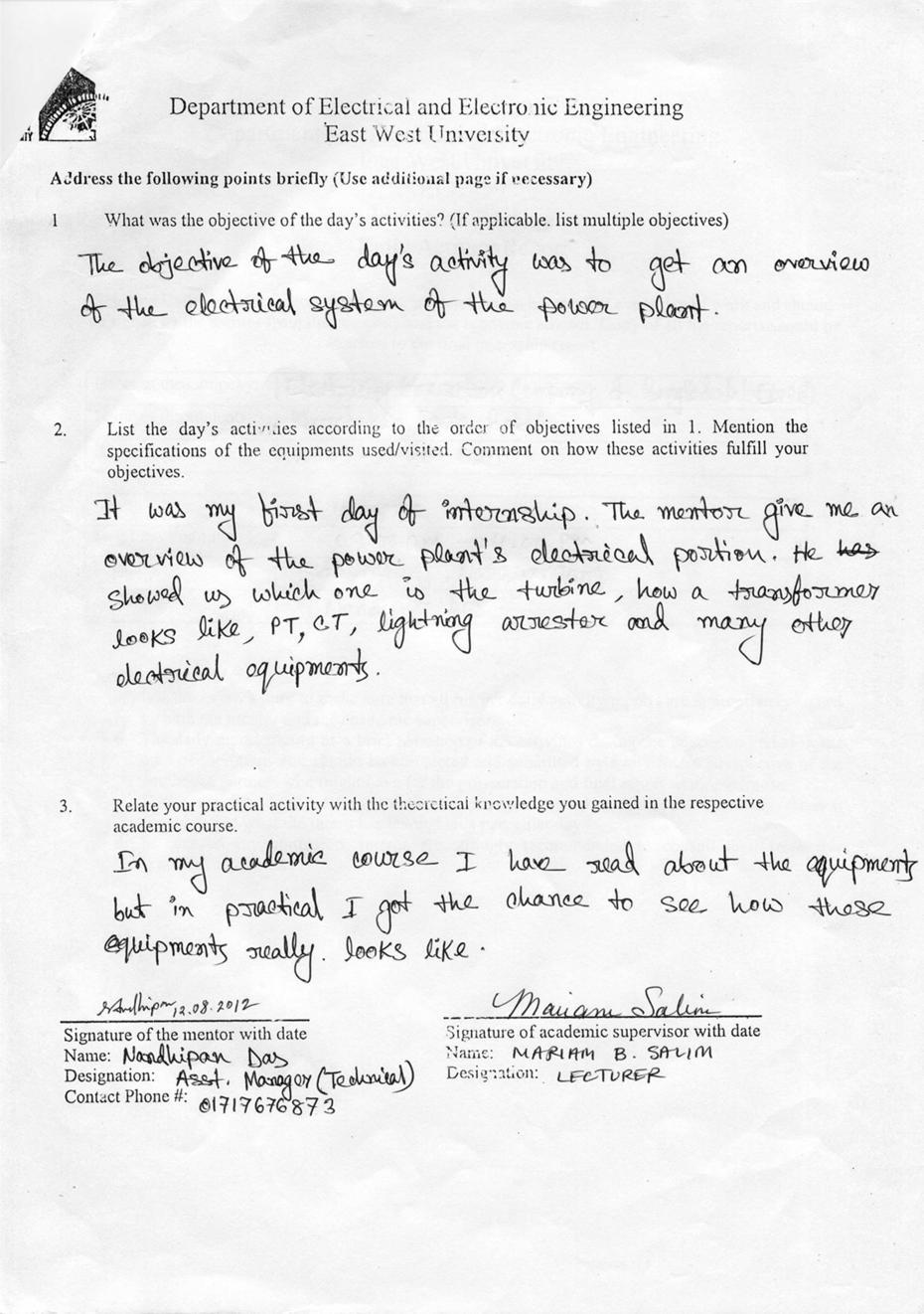
57 Daily Activity Report 56
58 57
59 58
60 59
61 60
62 61
63 62
64 63
65 64
66 65
67 66
68 67
69 68
70 69
71 70
72 71
73 72
74 73
75 74
76 75
77 76
78 77
79 78
80 79
81 80
82 81
83 82
84 83
85 84
86 85
Short Term Course On Hydropower Development Engineering (Electrical) for Teachers of Polytechnics in Uttarakhand L33-2
 for Teachers of Polytechnics in Uttarakhand L33-2") Short Term Course On Hydropower Development Engineering (Electrical) for Teachers of Polytechnics in Uttarakhand ( July 14-18, 2007) Lecture on L33-2 By S.N.Singh Senior Scientific officer ALTERNATE HYDRO
Short Term Course On Hydropower Development Engineering (Electrical) for Teachers of Polytechnics in Uttarakhand ( July 14-18, 2007) Lecture on L33-2 By S.N.Singh Senior Scientific officer ALTERNATE HYDRO
34 th Hands-On Relay School
 34 th Hands-On Relay School Generation Track Overview Lecture Generator Design, Connections, and Grounding 1 Generator Main Components Stator Core lamination Winding Rotor Shaft Poles Slip rings Stator
Chapter 6 Generator-Voltage System
 Chapter 6 Generator-Voltage System 6-1. General The generator-voltage system described in this chapter includes the leads and associated equipment between the generator terminals and the low-voltage terminals
AIR INSULATED EXTENDABLE SWITCHGEAR UP TO 12KV GUIDE
 AIR INSULATED EXTENDABLE SWITCHGEAR UP TO 12KV GUIDE Certificate Number FM35831 APPLICATION Typical Uses and Classification The MSGair switchgear is used in transformer and switching substations mainly
Power systems Protection course
 Al-Balqa Applied University Power systems Protection course Department of Electrical Energy Engineering Dr.Audih 1 Part 3 Protective Devices Fuses & Circuit Breakers 2 Introduction: Fuse Is advice used
PRAGATI ENGINEERING COLLEGE
 Report on Industrial Visit to Power Grid 765/400 KV (GIS) Sub-Station No. of days of Visit : Two days Date(s) of Visit : 19 th September, 2017& 7 th October, 2017 Faculty In-charges : 4 Members 1. Mr.S.Ashokreddy,
SQA Advanced Unit specification: general information
 SQA Advanced Unit specification: general information Unit title: Electrical Machine Principles Unit code: HT83 47 Superclass: XJ Publication date: August 2017 Source: Scottish Qualifications Authority
Double earth fault in a PSP during back to back launching sequence
 Double earth fault in a PSP during back to back launching sequence Jean-Louis DROMMI EDF Hydro Engineering Center, France Pump Storage Scheme, back to back launching Electricité de France Hydro Department
S. COMMERCIAL ENTERPRISE. Turbine Service & Supply of Spare Parts
 Turbine Service & Supply of Spare Parts Solutions with a Difference S. Commercial Enterprise headquartered in Bangladesh having global offices in Singapore and USA. S. Commercial Enterprise staff consists
Modular Standardized Electrical and Control Solutions for Fast Track Projects
 Modular Standardized Electrical and Control Solutions for Supporting fast track projects ABB is the leading supplier of electrical and control equipment for power plants. The company offers a comprehensive
Training Title GAS TURBINE AND COMPRESSOR OPERATION, MAINTENANCE AND TROUBLESHOOTING
 Training Title GAS TURBINE AND COMPRESSOR OPERATION, MAINTENANCE AND TROUBLESHOOTING Training Duration 5 days Training Venue and Dates Gas Turbine and Compressor Operation, Maintenance and Troubleshooting
NXPLUS C Single busbar. Maintenance-free for lifetime
 NXPLUS C Single busbar Maintenance-free for lifetime Energy Distribution Welcome! Page 2 Content Overview Technical data Typicals Panel design Circuit-Breaker panel Busbar Operation Metering Low-voltage
KONČAR Group. Research and Development
 production program 2 KONČAR Group KONČAR Group consists of 20 companies and has around 4000 employees. Annual sales account for more than 300 million euros, with almost half the amount in exports. KONČAR
INTERNSHIP REPORT POWER GENERATION, TRANSMISSION, DISTRIBUTION AND PROTECTION SYSTEM EQUIPMENT OF DUTCH BANGLA POWER & ASSOCIATES LTD.
 INTERNSHIP REPORT ON POWER GENERATION, TRANSMISSION, DISTRIBUTION AND PROTECTION SYSTEM EQUIPMENT OF DUTCH BANGLA POWER & ASSOCIATES LTD. (DBPAL) By DEENA FARZANA (2008-1-80-006) AMENA BEGUM (2008-1-80-038)
Feasibility of Electric Propulsion for Semi-submersible Heavy Lift Vessels
 Feasibility of Electric Propulsion for Semi-submersible Heavy Lift Vessels K Kokkila, ABB Marine & Cranes, Finland SUMMARY Some of the semi-submersible heavy lift vessels have special requirements that
CONCEPTUAL DESIGN OF A NEW TYPE OF ENGINE FOR VARIOUS APPLICATIONS WITH EXPECTED 10% HIGHER OVERALL EFFICIENCY
 International Journal of Mechanical and Production Engineering Research and Development (IJMPERD ) Vol.1, Issue 2 Dec 2011 58-65 TJPRC Pvt. Ltd., CONCEPTUAL DESIGN OF A NEW TYPE OF ENGINE FOR VARIOUS APPLICATIONS
Standby Power Systems
 Source: Power Quality in Electrical Systems Chapter 13 Standby Power Systems The term standby power systems describes the equipment interposed between the utility power source and the electrical load to
Chapter 6. Supercharging
 SHROFF S. R. ROTARY INSTITUTE OF CHEMICAL TECHNOLOGY (SRICT) DEPARTMENT OF MECHANICAL ENGINEERING. Chapter 6. Supercharging Subject: Internal Combustion Engine 1 Outline Chapter 6. Supercharging 6.1 Need
Data Bulletin. Ground-Censor Ground-Fault Protection System Type GC Class 931
 Data Bulletin 0931DB0101 July 2001 Cedar Rapids, IA, USA Ground-Censor Ground-Fault Protection System Type GC Class 931 09313063 GT Sensor Shunt Trip of Circuit Interrupter Window Area for Conductors GC
E-15 Uninterruptible Power Systems (UPS)
") Guideline No.E-15 (201705) E-15 Uninterruptible Power Systems (UPS) Issued date: May 9, 2017 China Classification Society Foreword This Guideline is a part of CCS Rules, which contains technical requirements,
Guideline No.E-15 (201705) E-15 Uninterruptible Power Systems (UPS) Issued date: May 9, 2017 China Classification Society Foreword This Guideline is a part of CCS Rules, which contains technical requirements,
Electrical Theory. Generator Theory. PJM State & Member Training Dept. PJM /22/2018
 Electrical Theory Generator Theory PJM State & Member Training Dept. PJM 2018 Objectives The student will be able to: Describe the process of electromagnetic induction Identify the major components of
BHARAT ALUMINIUM COMPANY LTD. SPECIFICATIONS FOR SYNCHRONOUS GENERATOR GENERAL Make : Jinan Power Equipment Factory Type : WX2
 BHARAT ALUMINIUM COMPANY LTD. SPECIFICATIONS FOR SYNCHRONOUS GENERATOR 1.00.00 GENERAL 1.01.00 Make : Jinan Power Equipment Factory 1.02.00 Type : WX21Z-073LLT 1.03.00 Reference Standard : GB/T7064-2002
Excitation system is of Static Silicon Excitation System, including excitation transformer, thyristors, and AVR.
 Turbo - Generator Type: QF Series 1. General The generator is a two pole, cylindrical rotor type synchronous machine, directly coupled with steam turbine. It has a closed-circuit cooling system to cool
Sub:EE6604/DESIGN OF ELECTRICAL MACHINES Unit V SYNCHRONOUS MACHINES. 2. What are the two type of poles used in salient pole machines?
 SRI VIDYA COLLEGE OF ENGINEERING & TECHNOLOGY DEPARTMENT OF EEEE QUESTION BANK Sub:EE6604/DESIGN OF ELECTRICAL MACHINES Unit V SYNCHRONOUS MACHINES 1. Name the two types of synchronous machines. 1. Salient
ISO Rules Part 500 Facilities Division 502 Technical Requirements Section Interconnected Electric System Protection Requirements
 Applicability 1 Section 502.3 applies to: the legal owner of a generating unit directly connected to the transmission system with a maximum authorized real power rating greater than 18 MW; the legal owner
In any of the 5 star hotels. The exact venue will be informed once finalized.
 Training Title ELECTRIC DISTRIBUTION SYSTEM EQUIPMENT: Transformers, Switchgears, Circuit Breakers, Relays, Capacitors, Surge Arresters, Cables & Meters: Operation, Inspection, Testing, Evaluation, Maintenance
5kV to 38kV, 630 Amp to 4000 Amp Indoor or Outdoor Application
 The most advanced Arc-Resistant Switchgear, designed and built to provide maximum safety in the event of an Internal Arcing Fault. 5kV to 38kV, 630 Amp to 4000 Amp Indoor or Outdoor Application Page 1
GENERATION, CONVERSION, OR DISTRIBUTION OF ELECTRIC POWER
 XXXX H02 GENERATION, CONVERSION, OR DISTRIBUTION OF ELECTRIC POWER XXXX CONTROL OR REGULATION OF ELECTRIC MOTORS, GENERATORS, OR DYNAMO-ELECTRIC CONVERTERS; CONTROLLING TRANSFORMERS, REACTORS OR CHOKE
SF 6 Gas Insulated Switchgear Type SDH714 for 72.5 to 145 kv
 Three-phase Encapsulated Type SF 6 Gas Insulated Switchgear Type SDH714 for 72.5 to 145 kv 06B1-E-0020 Small Space Requirement, High Reliability and Safety ー 72.5 to 145kV GIS, SDH714 The number of application
Research and Reviews: Journal of Engineering and Technology
 Research and Reviews: Journal of Engineering and Technology Brushless Excitation System of Turbo Generator Komala Koila* Department of Electrical and Electronics, Khammam Institute of Technology and Sciences,
Oil Circuit Breakers
 ČESKÉ VYSOKÉ UČENÍ TECHNICKÉ V PRAZE Fakulta elektrotechnická Katedra elektrických pohonů a trakce K13114 BE1M 14 ESP Electrical apparatuses and machines Oil Circuit Breakers BE1M14 SSP Electrical apparatuses
Medium Voltage Standby non-paralleling Control GUIDE FORM SPECIFICATION
 Medium Voltage Standby non-paralleling Control 1. GENERAL GUIDE FORM SPECIFICATION A. The requirements of the contract, Division 1, and part 16 apply to work in this section. 1.01 SECTIONS INCLUDE A. Medium
School of Electrical and Information Engineering. ELEC High Voltage. University of Sydney. Dr Keith Mitchell. Engineering
 University of Sydney School of Electrical and Information Engineering Dr Keith Mitchell ELEC 5205 - High Voltage Engineering ELEC 5205 - High Voltage Engineering 3. Switchgear Types of Power System Switchgear
KYN28-12(GZSI-12Z)Armoured Middle-Mounted Metal. Enclosed Switch. 1.General. 2.Model Definition
Armoured Middle-Mounted Metal. Enclosed Switch. 1.General. 2.Model Definition") KYN28-12(GZSI-12Z)Armoured Middle-Mounted Metal Enclosed Switch 1.General KYN28-12 armoured middle-mounted metal enclosed switchgear (hereinafter referred to as switchgear) is a new product with own design
KYN28-12(GZSI-12Z)Armoured Middle-Mounted Metal Enclosed Switch 1.General KYN28-12 armoured middle-mounted metal enclosed switchgear (hereinafter referred to as switchgear) is a new product with own design
MAHALAKSHMI ENGINEERING COLLEGE TIRUCHIRAPALLI
 MAHALAKSHMI ENGINEERING COLLEGE TIRUCHIRAPALLI 621213 QUESTION BANK --------------------------------------------------------------------------------------------------------------- Sub. Code : EE2402 Semester
GENERAL The Honeywell model TFE731-40AR turbofan engine is a lightweight, two-spool, geared-stage, front-fan, jet engine.
 ENGINE GENERAL The Honeywell model TFE731-40AR turbofan engine is a lightweight, two-spool, geared-stage, front-fan, jet engine. The cross section of the engine is shown in Figure 7-71-1, page VII-71-3.
P2 : About Us. P3 : Elsewedy Transformers. P4 : Why Elsewedy Dry Type Transformer? P6 : Cast Resin Dry Transformers. P7 : Technical Data Sheets
 P2 : About Us P3 : Elsewedy Transformers P4 : Why Elsewedy Dry Type Transformer? P6 : Cast Resin Dry Transformers P7 : Technical Data Sheets P8 : Transformer s Outline Drawing P9 : Accessories About Us
Question Set(2017) Switch Gear & protection(5 th SEm) 9. Explain the construction and operating principle with proper diagram:
 Switch Gear & protection(5 th SEm) 9. Explain the construction and operating principle with proper diagram:") Question Set(2017) Switch Gear & protection(5 th SEm) 1. What is fault in power system? Classify the fault. What are the bad effects of fault? 2. Define with example: Symmetrical fault and unsymmetrical
Question Set(2017) Switch Gear & protection(5 th SEm) 1. What is fault in power system? Classify the fault. What are the bad effects of fault? 2. Define with example: Symmetrical fault and unsymmetrical
Section 3 Technical Information
 Section 3 Technical Information In this Module: Engine identification Modes of operation Battery charging and heat manage operation Service and repair procedures Maintenance requirements Engine Identification
SafeGear Motor Control Center Arc Resistant Metal-Clad Construction Brochure
 2017 SafeGear Motor Control Center Arc Resistant Metal-Clad Construction Brochure SafeGear Motor Control Center Arc resistant Metal-Clad construction Brochure Table of Contents 1. Description 1 1 2. SafeGear
Unified requirements for systems with voltages above 1 kv up to 15 kv
 (1991) (Rev.1 May 2001) (Rev.2 July 2003) (Rev.3 Feb 2015) (Corr.1 June 2018) Unified requirements for systems with voltages above 1 kv up to 15 kv 1. General 1.1 Field of application The following requirements
A comparison of metal-enclosed load interrupter (ME) switchgear and metal-clad (MC) switchgear
 switchgear and metal-clad (MC) switchgear") Robert J. Gustin Eaton Fellow Application Engineer, P. E. Southfield, Michigan Definitions Metal-enclosed load interrupter switchgear type ME Metal-enclosed switchgear is defined in ANSI C37.20.3-1987,
Robert J. Gustin Eaton Fellow Application Engineer, P. E. Southfield, Michigan Definitions Metal-enclosed load interrupter switchgear type ME Metal-enclosed switchgear is defined in ANSI C37.20.3-1987,
GE Consumer & Industrial Power Protection. New. SecoGear kV Metal-clad Switchgear. GE imagination at work
 GE Consumer & Industrial Power Protection New SecoGear 12-24kV GE imagination at work General SecoGear metal-clad switchgear is designed and manufactured with advance technology and has been comprehensively
CHAPTER 3 CAUSES AND EFFECTS OF ELECTRICAL FAULTS
 22 CHAPTER 3 CAUSES AND EFFECTS OF ELECTRICAL FAULTS 3.1 INTRODUCTION A large number of asynchronous motors are used in industrial processes even in sensitive applications. Consequently, a defect can induce
Global VPI Insulated Indirectly Hydrogen-Cooled Turbine Generator for Single-Shaft Type Combined Cycle Power Generation Facilities
 Global VPI Insulated Indirectly Hydrogen-Cooled Turbine Generator for Single-Shaft Type Combined Cycle Power Generation Facilities YAMAZAKI Masaru NIIKURA Hitoshi TANIFUJI Satoshi ABSTRACT Fuji Electric
Switchgear and Distribution Systems for Engineers and Technicians
 Switchgear and Distribution Systems for Engineers and Technicians WHAT YOU WILL LEARN: How to identify typical characteristics of an industrial distribution system Become familiar with the main components
UBC Technical Guidelines Section Edition Commissioning of Electrical Systems Page 1 of 5
 Page 1 of 5 1.0 GENERAL 1.1 Coordination Requirements.1 UBC Building Operations Electrical Technical Support.2 UBC Energy & Water Services 2.0 REQUIREMENTS FOR COMMISSIONING AND TESTING 2.1 Testing.1 Unit
INSTITUTE OF AERONAUTICAL ENGINEERING Dundigal, Hyderabad
 INSTITUTE OF AERONAUTICAL ENGINEERING Dundigal, Hyderabad - 500 043 MECHANICAL ENGINEERING ASSIGNMENT Name : Electrical and Electronics Engineering Code : A40203 Class : II B. Tech I Semester Branch :
Bombardier Challenger Auxiliary Power Unit
 GENERAL A Honeywell 36 150(CL) constant-speed gas turbine auxiliary power unit (APU) is installed within a fire-resistant compartment in the aft equipment bay. The APU drives a generator, providing AC
A system fault contribution of 750 mva shall be used when determining the required interrupting rating for unit substation equipment.
 General Unit substations shall be 500 kva minimum, 1500 kva maximum unless approved otherwise by the University. For the required configuration of University substations see Standard Electrical Detail
Service and Rehabilitation Electrical Power Systems
 Service and Rehabilitation Electrical Power Systems From water to wire 3 ANDRITZ HYDRO Electrical Power System Modernization and rehabilitation International technology group ANDRITZ is a globally leading
Ignition Reliability in SGT-750 for Gas Blends at Arctic Conditions. Magnus Persson Combustion Expert / Distributed Generation / Sweden
 Ignition Reliability in SGT-750 for Gas Blends at Arctic Conditions Magnus Persson Combustion Expert / Distributed Generation / Sweden siemens.com/power-gas Table of content Objectives of the Project SGT-750
Diesel Power Generating Plants. Introduction
 Diesel Power Generating Plants Introduction Steve Mackay Dean of Engineering Worked for 30 years in Industrial Automation 30 years experience in mining, oil and gas, electrical and manufacturing industries
Christian Ohler, ABB Switzerland Corporate Research Physics of Electric Power Systems. ABB Group August 1, 2012 Slide 1
 Christian Ohler, ABB Switzerland Corporate Research Physics of Electric Power Systems ABB Group August 1, 2012 Slide 1 Purpose of this Presentation Describe power systems from a physicists point of view
SECTION 4 ELECTRIC MOTORS UNIT 17: TYPES OF ELECTRIC MOTORS UNIT OBJECTIVES UNIT OBJECTIVES 3/21/2012
 SECTION 4 ELECTRIC MOTORS UNIT 17: TYPES OF ELECTRIC MOTORS UNIT OBJECTIVES After studying this unit, the reader should be able to Describe the different types of open single-phase motors used to drive
The University of New South Wales. School of Electrical Engineering and Telecommunications. Industrial and Commercial Power Systems Topic 2
 The University of New South Wales School of Electrical Engineering and Telecommunications Industrial and Commercial Power Systems Topic 2 SWITCHBOARDS Overview Also called Switchgear and Controlgear Assembly
Metrovick F2/4 Beryl. Turbo-Union RB199
 Turbo-Union RB199 Metrovick F2/4 Beryl Development of the F2, the first British axial flow turbo-jet, began in f 940. After initial flight trials in the tail of an Avro Lancaster, two F2s were installed
SLOVAK UNIVERSITY OF TECHNOLOGY Faculty of Material Science and Technology in Trnava ELECTRICAL ENGINEERING AND ELECTRONICS.
 SLOVAK UNIVERSITY OF TECHNOLOGY Faculty of Material Science and Technology in Trnava ELECTRICAL ENGINEERING AND ELECTRONICS Róbert Riedlmajer TRNAVA 2007 Unit 14 - Fundamentals of power system protection
PRACTICAL TROUBLESHOOTING OF ELECTRICAL EQUIPMENT & CONTROL SYSTEMS
 Training Title PRACTICAL TROUBLESHOOTING OF ELECTRICAL EQUIPMENT & CONTROL SYSTEMS Training Duration 5 days Training Venue and Dates Practical Troubleshooting Of Electrical Equipment & Control Systems
Installation- and maintenance instruction BENTOFLEX ST 108 PL
 Installation- and maintenance instruction BENTOFLEX ST 108 PL 1 171 625 30 03-01 178 001 13 DESCRIPTION COMPONENTS 1. Reset button 2. Control box 3. Ignition transformer 4. Ignition cables 5. Nozzle assembly
Key elements of the AS3000 Wiring standards and some of the recent changes.
 Key elements of the AS3000 Wiring standards and some of the recent changes. Dean of Engineering Steve Mackay Worked for 30 years in Industrial Automation 30 years experience in mining, oil and gas, electrical
CHAPTER 6 IGNITION SYSTEM
 CHAPTER 6 CHAPTER 6 IGNITION SYSTEM CONTENTS PAGE Faraday s Law 02 The magneto System 04 Dynamo/Alternator System 06 Distributor 08 Electronic System 10 Spark Plugs 12 IGNITION SYSTEM Faraday s Law The
Protection for 2500KVA High Tension Transformer Ankita S.Kulkarni 1, Priyanka S.Dhayarkar 2, Harsha H.Ambure 3, Ashwini S.Shinde 4
 Protection for 2500KVA High Tension Transformer Ankita S.Kulkarni 1, Priyanka S.Dhayarkar 2, Harsha H.Ambure 3, Ashwini S.Shinde 4 Graduate Student, Dept. of E&TC, Pimpri Chinchwad College of Engineering,
Basics of Paralleling
 Basics of Paralleling Revised: February 1, 2017 2017 Cummins All Rights Reserved Course Objectives Participants will be able to: Discuss basic paralleling control functions to gain a better understanding
8DJ. Maintenance-free for lifetime
 8DJ Maintenance-free for lifetime Energy Distribution Welcome! Page 2 October 1 st 2008 8DJ Main Applications for Medium-Voltage Switchgear Power generation Power stations G Power transmission High and
ZF SERIES HV GAS INSULATED SWITCHGEAR (GIS) tgood.com. Energy. Fast.
 tgood.com. Energy. Fast.") ZF SERIES HV GAS INSULATED SWITCHGEAR (GIS) tgood.com Energy. Fast. TGOOD produces over 5000 switchgear units annually for projects around the globe PRODUCT OVERVIEW High performance alternative to air
ZF SERIES HV GAS INSULATED SWITCHGEAR (GIS) tgood.com Energy. Fast. TGOOD produces over 5000 switchgear units annually for projects around the globe PRODUCT OVERVIEW High performance alternative to air
Technical Guide No. 7. Dimensioning of a Drive system
 Technical Guide No. 7 Dimensioning of a Drive system 2 Technical Guide No.7 - Dimensioning of a Drive system Contents 1. Introduction... 5 2. Drive system... 6 3. General description of a dimensioning
University of Houston Master Construction Specifications Insert Project Name
 SECTION 26 13 13 MEDIUM VOLTAGE SWITCHGEAR PART 1 - GENERAL 1.1 RELATED DOCUMENTS: A. The Conditions of the Contract and applicable requirements of Divisions 0 and 1 and Section 26 00 01, Electrical General
9. Examples of hydro energy conversion
 9. Examples of hydro energy conversion VATech Hydro, Austria Prof. A. Binder 9/1 Variable speed pump storage power plant Prof. A. Binder 9/2 Conventional pump storage power plant with synchronous motor-generators
Summary of General Technical Requirements for the Interconnection of Distributed Generation (DG) to PG&E s Distribution System
 to PG&E s Distribution System") Summary of General Technical Requirements for the Interconnection of Distributed Generation (DG) to PG&E s Distribution System This document is intended to be a general overview of PG&E s current technical
Summary of General Technical Requirements for the Interconnection of Distributed Generation (DG) to PG&E s Distribution System This document is intended to be a general overview of PG&E s current technical
Electrical Systems. Introduction
 Electrical Systems Figure 1. Major Components of the Car s Electrical System Introduction Electricity is used in nearly all systems of the automobile (Figure 1). It is much easier to understand what electricity
XQ-5200 Solar T60 Gas Turbine-Generator 5,200 ekw Iso Conditions 13.8 kv
 XQ-5200 Solar T60 Gas Turbine-Generator 5,200 ekw Iso Conditions 13.8 kv XQ-5200_Specs.doc Page 1 of 11 Index 1. Overview... 3 2. Equipment... 4 3. Performance Data... 4 4. Gas Composition Requirement...
NEPAL ELECTRICITY AUTHORITY (A Government of Nepal Undertaking)
") NEPAL ELECTRICITY AUTHORITY (A Government of Nepal Undertaking) Generation Directorate Medium Generation Operation and Maintenance Department SUNDARIJAL HYDROPOWER PLANT REHABILITATION PROJECT Electricity
NEPAL ELECTRICITY AUTHORITY (A Government of Nepal Undertaking) Generation Directorate Medium Generation Operation and Maintenance Department SUNDARIJAL HYDROPOWER PLANT REHABILITATION PROJECT Electricity
SF 6 Gas Insulated Switchgear Type SDH314 / SDHa314 for 72.5 to 145 kv
 Three Phase Encapsulated Type SF 6 Gas Insulated Switchgear Type SDH314 / SDHa314 for 72.5 to 145 kv 06B1-E-0002 Small Space Requirement, High Reliability and Safety ー 72.5 to 145 kv GIS, SDH314/SDHa314
Motor Protection Fundamentals. Motor Protection - Agenda
 Motor Protection Fundamentals IEEE SF Power and Energy Society May 29, 2015 Ali Kazemi, PE Regional Technical Manager Schweitzer Engineering Laboratories Irvine, CA Copyright SEL 2015 Motor Protection
SION Vacuum Circuit-Breakers. Answers for energy. Medium-Voltage Equipment Selection and Ordering Data. Catalog HG
 Medium-Voltage Equipment Selection and Ordering Data Catalog HG 11.0 008 Answers for energy. R-HG11-17.tif Siemens HG 11.0 008 Contents Contents Page SION Vacuum Circuit-Breakers Description General Construction
Arc flash hazard mitigation
 Low Voltage Products Arc flash hazard mitigation Each year more than 2,000 people are treated in burn centers with severe arc flash injuries. ABB designs and manufactures products and solutions to provide
The University of New South Wales. School of Electrical Engineering and Telecommunications. Industrial and Commercial Power Systems Topic 6
 The University of New South Wales School of Electrical Engineering and Telecommunications Industrial and Commercial Power Systems Topic 6 PROTECTIONS 1 FUNCTION OF ELECTRICAL PROTECTION SYSTEMS Problems:
Introduction to Circuit Breaker. Working Principle of Circuit Breaker
 Definition of Circuit Breaker : - Electrical Circuit Breaker is a switching device which can be operated manually as well as automatically for controlling and protection of electrical power system respectively.
ALTERNATOR STARTUP Turning gear to full operation. Procedure initiated by:. 7/03 Before starting procedure, remove all check marks.
 ALTERNATOR STARTUP Turning gear to full operation. Procedure initiated by:. 7/03 Before starting procedure, remove all check marks. 1. Check log book for incomplete compliance for further operation. 2.
Renewable Energy Systems 13
 Renewable Energy Systems 13 Buchla, Kissell, Floyd Chapter Outline Generators 13 Buchla, Kissell, Floyd 13-1 MAGNETISM AND ELECTROMAGNETISM 13-2 DC GENERATORS 13-3 AC SYNCHRONOUS GENERATORS 13-4 AC INDUCTION
CHAPTER 3 DESIGN OF THE LIMITED ANGLE BRUSHLESS TORQUE MOTOR
 33 CHAPTER 3 DESIGN OF THE LIMITED ANGLE BRUSHLESS TORQUE MOTOR 3.1 INTRODUCTION This chapter presents the design of frameless Limited Angle Brushless Torque motor. The armature is wound with toroidal
Gas Insulated Metal-clad Switchgear, HMGS!
 Medium Voltage HMGS-G10 HYUNDAI Medium Voltage Gas Insulated Metal-clad Switchgear, HMGS! SF6 Gas Insulated Metal-clad Switchgear is an integrated assembly of vacuum circuit breaker, 3-position switch,
E-12 Low-voltage Switchboard
 Guideline No.E-12 (201510) E-12 Low-voltage Switchboard Issued date: 20 October 2015 China Classification Society Foreword This Guide is a part of CCS Rules, which contains technical requirements, inspection
ZX1.5-R. Gas-insulated medium voltage for railway application DISTRIBUTION SOLUTIONS. Gas-insulated medium voltage for railway application ZX1.
 DISTRIBUTION SOLUTIONS ZX1.5-R Gas-insulated medium voltage for railway application Safety and reliability 20% footprint saving Easy operation Complete solution ZX1.5-R Gas-insulated medium voltage for
INTER PLANT STANDARD STEEL INDUSTRY SPECIFICATION FOR STATIC EXCITATION CONVERTORS FOR SYNCHRONOUS MOTORS (FIRST REVISION)
") INTER PLANT STANDARD STEEL INDUSTRY I P S S SPECIFICATION FOR STATIC EXCITATION CONVERTORS FOR SYNCHRONOUS MOTORS (FIRST REVISION) Corresponding IS does not exist IPSS: 1-10-036-12 0 FOREWORD 0.1 This
INTER PLANT STANDARD STEEL INDUSTRY I P S S SPECIFICATION FOR STATIC EXCITATION CONVERTORS FOR SYNCHRONOUS MOTORS (FIRST REVISION) Corresponding IS does not exist IPSS: 1-10-036-12 0 FOREWORD 0.1 This
Failure of Transformer Cable box A case study
 Failure of Transformer Cable box A case study Presented by Janardan Choudhary, Executive Director (O&M) 1 INTRODUCTION The 280 MW Dhauliganga Power Station, NHPC Ltd, situated at remote place of Pithoragarh
Electric Utility Power Systems. Generation of Electricity
 Electric Utility Power Systems Generation of Electricity 1 Demand of an Electrical System The total power drawn by a customer of a large utility system fluctuates between wide limits, depending on the
EE 741 Over-voltage and Overcurrent. Spring 2014
 EE 741 Over-voltage and Overcurrent Protection Spring 2014 Causes of Over-voltages Lightning Capacitor switching Faults (where interruption occurs prior to zero current crossing) Accidental contact with
CATERPILLAR 3516B DP2 System
 CATERPILLAR 3516B DP2 System CONTENTS System Overview 3 Offshore Rig or Ship DP2 Package 3 Main Generator Diesel Skid 3 Main Generator Diesel Engines 3 Instrument, Alarms and Automatic Start/Stop System
Distribution transformers Efficiency over life-cycle
 Distribution transformers Efficiency over life-cycle ABB a global leader ABB is a global leader in Power and Automation technologies that enable utility and industry customers to improve performance while
E-15 Uninterruptible Power Systems (UPS)
") Guideline No.E-15 (201510) E-15 Uninterruptible Power Systems (UPS) Issued date:20 October, 2015 China Classification Society Foreword This Guide is a part of CCS Rules, which contains technical requirements,
Guideline No.E-15 (201510) E-15 Uninterruptible Power Systems (UPS) Issued date:20 October, 2015 China Classification Society Foreword This Guide is a part of CCS Rules, which contains technical requirements,
INESING srl. MOBILE SUBSTATIONS Energy Solution. Energy Innovation. INESING srl Energy Innovation
 MOBILE SUBSTATIONS Energy Solution INTERNATIONAL FAIR MOBILE SUBSTATIONS ENERGY SOLUTION Complete design for energy s generations, transmission and distribution Mobile Substations Applications of Inesing
Lecture 27: Principles of Burner Design
 Lecture 27: Principles of Burner Design Contents: How does combustion occur? What is a burner? Mixing of air and gaseous fuel Characteristic features of jet Behavior of free (unconfined) and confined jet
EE069: Electrical Engineering for Non-Electrical Engineers
 EE069: Electrical Engineering for Non-Electrical Engineers EE069 Rev.002 CMCT COURSE OUTLINE Page 1 of 5 Training Description: This course introduces the Basic Principles of Electricity in a simple, easy
Product Specification
 KYN28-12 Series H.V Metal Clad Switchgear Product Specification 10/08/2015 Electrical Treasure One-Stop Supplier Of Electrical Equipment 1 KYN28-12 Series With Prevent Wrong Operation Of Metal Clad Switchgear
3.2. Current Limiting Fuses. Contents
 .2 Contents Description Current Limiting Applications................. Voltage Rating.......................... Interrupting Rating....................... Continuous Current Rating................ Fuse
CHAPTER 6 INTRODUCTION TO MOTORS AND GENERATORS
 CHAPTER 6 INTRODUCTION TO MOTORS AND GENERATORS Objective Describe the necessary conditions for motor and generator operation. Calculate the force on a conductor carrying current in the presence of the
TRT SYSTEM. Product Description
 TRT SYSTEM Product Description The TRT is a machine that exploits the flow and the pressure of the furnace output gas to produce electric energy. Through a system of regulation managed by PLC it maintains
ELECTRIC POWER AND HOUSEHOLD CIRCUITS
 ELECTRIC POWER AND HOUSEHOLD CIRCUITS HEATING EFFECT OF CURRENT Heating effect of electricity is one of the widely-used effects in the world. When electric current is passed through a conductor, it generates