»Product» Safety Warning
|
|
|
- Meryl Ross
- 5 years ago
- Views:
Transcription
1 C2610, C2611 Installation Instructions Chevy/GM Pickup 1/2 Ton 4wd 6" Suspension Lift Read and understand all instructions and warnings prior to installation of product and operation of vehicle. Zone Offroad Products recommends this system be installed by a professional technician. In addition to these instructions, professional knowledge of disassembly/ reassembly procedures and post installation checks must be known. Minimum tool requirements include the following: Assorted metric and standard wrenches, hammer, hydraulic floor jack and a set of jack stands. See the "Special Tools Required" section for additional tools needed to complete this installation properly and safely.»product» Safety Warning Certain Zone Suspension Products are intended to improve off-road performance. Modifying your vehicle for off-road use may result in the vehicle handling differently than a factory equipped vehicle. Extreme care must be used to prevent loss of control or vehicle rollover. Failure to drive your modified vehicle safely may result in serious injury or death. Zone Offroad Products does not recommend the combined use of suspension lifts, body Difficulty Level lifts, or other lifting devices. You should never operate your modified vehicle under the influence of alcohol or drugs. Always drive your modified vehicle at reduced speeds to ensure your ability to control your vehicle under all driving conditions. Always wear your seat belt.»technical» Support Live Chat provides instant communication with Zone tech support. Anyone can access live chat through a link on may have additional information about this product including the latest instructions, videos, photos, etc. Send an to tech@zoneoffroad.com detailing your issue for a quick response ZONE Call to speak directly with Zone tech support.»pre-installation» Notes 1. Special literature required: OE Service Manual for model/year of vehicle. Refer to manual for proper disassembly/reassembly procedures of OE and related components. 2. Adhere to recommendations when replacement fasteners, retainers and keepers are called out in the OE manual. easy difficult Estimated installation: 8 hours Special Tools Required GM Style Torsion Bar Tool Welder Reciprocating Saw or Equivalent Drill w/ 1/2" Bit 36mm Axle Socket Tire/Wheel Fitment Tire: 35x12.50 Wheels: 20" x 8" w/ 5.75" BS 16 x 8" w/ 4.5" BS 3. Larger rim and tire combinations may increase leverage on suspension, steering, and related components. When selecting combinations larger than OE, consider the additional stress you could be inducing on the OE and related components. 4. Post suspension system vehicles may experience drive line vibrations. Angles may require tuning, slider on shaft may require replacement, shafts may need to be lengthened or trued, and U-joints may need to be replaced. 5. Secure and properly block vehicle prior to installation of Zone Offroad Products. Always wear safety glasses when using power tools. 6. If installation is to be performed without a hoist, Zone Offroad Products recommends rear alterations first. 7. Due to payload options and initial ride height variances, the amount of lift is a base figure. Final ride height dimensions may vary in accordance to original vehicle attitude. Always measure the attitude prior to beginning installation.»» Zone Offroad Products 491 W. Garfield Ave., Coldwater, MI ZONE rev072312
 1 Differential")
 2 Bump Stop 1 Differential Skid Plate 2 CV")
 2 Large Hourglass Bushing (T-Bar Drop) 4 Sleeve - 0.750\" x 0.090\" x 1.")

 REAR")
 DIFF SKID PLATE TORSION BAR DROP (2 - PASS.")
2 Kit Contents Qty Part 1 Steering Knuckle (drv) 1 Steering Knuckle (pass) 1 Front Crossmember 1 Rear Crossmember 1 Differential Drop Bracket (drv) 1 Differential Bracket Spacer 2 Bushing - Drv. Differential Brkt 1 Sleeve " x 0.083" x 2.955" 1 Differential Drop Bracket (pass) 2 Bump Stop 1 Differential Skid Plate 2 CV Spacer 2 Compression Tube 1 Torsion Bar Drop Brkt (drv) 1 Torsion Bar Drop Brkt (pass) 2 Large Hourglass Bushing (T-Bar Drop) 4 Sleeve " x 0.090" x 1.575" 2 Sway Bar Link 2 Sway Bar Link U-Bracket 2 Small Hourglass Bushing 4 Stem Bushing 4 Stem Washer 1 Weld-in Support Plate 2 Rear Bump Stop Spacer 2 Rear 5" Lift Block 4 9/16" x 2-1/2" x 14" U-bolt, Nuts, Washers 5 Bolt Pack FRONT CROSSMEMBER REAR CROSSMEMBER PASSENGER'S DIFF BRKT SWAY BAR LINK BRKT (2) REAR BUMP STOP SPACER (2) CV SPACER (2) WELD-IN PLATE DRIVER'S DIFF BRKT SWAY BAR LINK (2) DIFF SKID PLATE TORSION BAR DROP (2 - PASS. SIDE SHOWN) COMPRESSION STRUT (2) pg. 2 - C2610 Installation

3 INSTALLATION INSTRUCTIONS 1. Park the vehicle on a flat, clean surface and block the rear wheels for safety. 2. Disconnect the positive and negative battery cables.»front» Installation 3. Raise the front of the vehicle and support with jack stands under the frame rails. 4. Remove the wheels. 5. Measure and record the length of the exposed thread on the torsion bar adjuster bolts (Figure 1). Record the lengths here for use later during the installation DRV Side: PASS Side: Important measure before starting! Measure from the center of the wheel up to the bottom edge of the wheel opening LF RF LR RR Figure 1 6. Unload the torsion bars but do not remove. Save adjuster bolt/retainer block. 7. Mark the unloaded torsion bars to indicate DRV side and PASS side. Also mark the bars to indicate front versus rear. 8. Remove the torsion bar adjuster plate by pushing the torsion bar forward to allow the plate to drop free. On most vehicles this will require a using a hammer/ punch or air hammer. Access the end of the torsion bar through the hole in the back of the torsion bar crossmember and drive forward. Leave the torsion bars in the lower control arms. 9. Remove the two bolts that attach the torsion bar crossmember to the frame rails (Figure 2). Remove the torsion bar crossmember from the vehicle. Save bolts and crossmember. Step 6 Note Unloading torsion bars: Torsion bars are under pressure even with the front suspension off the ground. A proper torsion bar tool is necessary to unload and remove the torsion bars from the vehicle. A tool designed specifically for GM torsion bars (#J36202 or equivalent) is required. This tool can be purchased from several sources and most part stores will lend these tools for little or no charge. Follow the individual tool instructions for proper use. C2610 Installation - pg. 3
. This will not be reused. Figure 3 12.")
. Remove the tie rod ends from the knuckles. 14.")
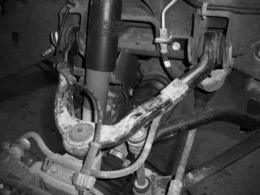
4 Figure Remove the torsion bars by pulling them rearward out of the lower control arms. Set the torsion bars aside. 11. If equipped, remove the four bolts mounting the factory belly pan to the frame (Figure 3). This will not be reused. Figure Disconnect the sway bar end links from the sway bar and the lower control arms (Figure 4). Discard the link assemblies. 13. Disconnect the tie rod ends from the steering knuckles. Remove the tie rod end nuts and save. Strike the knuckle near the tie rod end to dislodge the tie rod end taper (Figure 4). Remove the tie rod ends from the knuckles. 14. Disconnect the ABS brake wire from the connector at the top of the frame (Figure 5). Remove the wire from the plastic retainers on the frame and upper control arm (Figure 6). 15. Disconnect the rubber brake line brackets from the upper control arm and the steering knuckle (Figure 6). Save hardware. pg. 4 - C2610 Installation


5 Figure 4 Figure 5 Figure 6 C2610 Installation - pg. 5
. Do not hang the caliper by the brake hose. Save mounting bolts.")


6 16. Remove the two bolts mounting the brake caliper assembly to the steering knuckle and hang the caliper out of the way (Figure 7). Do not hang the caliper by the brake hose. Save mounting bolts. Figure 7 Step 18 Note A fine-tipped chisel and hammer work well to remove the hub dust cap. Work the chisel around the cap to separate it from the hub. 17. If equipped, remove the rotor retaining clips from the wheels studs. These will not be reused. Remove the brake rotor and set aside. 18. Carefully remove the hub dust cover. 19. Remove the CV axle nut and washer (Figure 8). Save hardware. Figure Remove the CV axle flange bolts at the differential (Figure 9). There are 6 bolts per side. Discard the bolts. pg. 6 - C2610 Installation
 and remove the ball joint from the knuckle. Allow the knuckle to swing out and remove the CV axle from the hub (Figure 10).")

7 Figure Remove the upper ball joint nut. Thread the nut back on by hand one or two turns. Strike the knuckle near the upper ball joint to release the taper. Remove the upper ball joint nut (save) and remove the ball joint from the knuckle. Allow the knuckle to swing out and remove the CV axle from the hub (Figure 10). Mark the CV axle to indicate DRV side and PASS side. Figure Remove the lower ball joint nut and thread back on by hand one or two turns. Strike the knuckle near the ball joint to release the taper. Remove the ball joint nut and remove the knuckle from the lower control arm. Save the lower ball joint nut and set the knuckle/hub assembly aside. 23. Disconnect the shocks from the frame and lower control arm. Remove shocks, save lower mounting hardware and discard the rest. 24. Remove the front and rear lower control arm bolts and remove the control arms from the vehicle (Figure 11). Save the control arms and mounting hardware. C2610 Installation - pg. 7
.")


8 Figure Remove the factory bump stops from the frame (Figure 12). A pair of channel locks work well for this. Figure Make an alignment mark on the front driveshaft and front differential input yoke. Remove the four bolts/clamps from the yoke and remove the front driveshaft from the differential (Figure 13). Save the driveshaft hardware. pg. 8 - C2610 Installation Figure 13
. Remove the wire from the three plastic wire retainers along the top of the differential. 29.")

9 27. Remove the four bolts mounting the rear crossmember to the rear lower control arm pockets (Figure 14). Remove the crossmember from the vehicle. The crossmember and hardware will not be reused. Figure Disconnect the electrical connector from the front differential actuator (Figure 11). Remove the wire from the three plastic wire retainers along the top of the differential. 29. Disconnect the axle breather tube from the driver's side of the differential. 30. Loosen but do not remove all of the front differential mounting bolts. There are two on the passenger's side, one on the upper front driver's side and one on the lower rear driver's side. 31. Locate the remaining wing of the rear crossmember on the lower rear driver's side control arm pocket. This portion of the frame must be removed to clear the front differential in its new, lower position. A precise measurement and cut is outlined later in the instructions but to make removing the differential easier the wing portion can be cut off now. Using a reciprocating saw (recommended), hack saw or cut-off wheel, remove the wing just inside of the control arm pocket (Figure 15). Take care not to cut into the differential housing or bolt. Step 31 Note Do not use any type of flamecutting to cut on the frame. The vehicle undercoating is flamable. Figure Support the front differential with an appropriate jack. Remove the differential mounting hardware and lower the differential from the vehicle and set aside. Save hardware. C2610 Installation - pg. 9
.")

10 Step 33 Note Measure twice, cut once! 33. The lower rear driver's side control arm pocket must be trimmed to provide clearance for the front differential. Measure inward from the lower control arm mounting hole 1-3/4" and mark on both the front and back surfaces of the pocket (Figure 16). Make vertical cut lines at the marks and connect the cut lines along the top surface of the pocket. 1-3/4 Figure 16 Step 35 Note It is important to completely remove the undercoating around the area to be welded. This will avoid weld contamination, as well as the undercoating igniting/melting. 34. Using a reciprocating saw (recommended), hack saw or cut-off wheel, cut the pocket along cut lines. 35. With the control arm pocket trimmed, be sure the area around the cut is free from grease, oil and undercoating. Locate the provided weld-in support plate and place it up to the frame where the cut was made. The chamfered corners or the plate go to the top. Align the bottom of the plate to the bottom edge of the control arm pocket and center the plate horizontally in the pocket. Tack weld the plate in place. 36. With the support plate tack in place, double check the location and then finish welding it in place (Figure 17). Allow the area to cool slowly and then paint any exposed metal to prevent rust. Figure The front upper mount bushing of the differential must be removed to provided adequate steering clearance. Mark a cut line around the mount that is flush with the top of the differential housing. Using a reciprocating saw (recommended) or hack saw, cut the mount off of the differential (Figure 18). Take extra care not to cut into the differential housing. pg C2610 Installation


11 Figure Install the provided large bushings (2) and 0.750" OD x 2.955" long sleeve into the eye of the new driver's side differential bracket. 39. Install the bushings and sleeve in the C-shaped differential housing bracket. Set the differential housing bracket up to the housing in the appropriate location and remove the four housing bolts that correspond to the holes in the bracket (Fig 10). Using three 10mm x 60mm bolts and washers, attach the bracket to the differential housing in the tapped factory holes. Attach the remaining location with 10mm x 70mm bolt with washers, spacer sleeve, and locknut. Torque the bolts to 30 ft-lbs. Use Loctite on mounting bolts that thread into the housing. Note: While working with the differential housing it is normal for some fluid leakage to occur. Check and fill as necessary when installation is complete. Step 39 Note Differential bolts/washers are located in hardware pack #567 Figure Locate the new passenger's side differential bracket. Install the bracket on the existing studs on the passenger's side factory bracket. Fasten with the original nuts and washers. When installed the open side of the bracket will face inward and the bracket will taper down as it goes to the rear (Figure 20). Torque nuts to 65 ft-lbs. C2610 Installation - pg. 11
. This will allow the new cross members to be installed easily.")

12 Figure Inspect the inside factory control arm mounting holes. The will be a sharp lip left from the original control arm/hardware. Use a file or rotary grinder to remove the sharp lip left from the control arms (Figure 21). This will allow the new cross members to be installed easily. Figure Locate the new front crossmember. Install the crossmember in the front lower control arm pockets so that the two longer differential mounting tabs are on the driver's side pointing reward (Figure 22). Fasten the crossmember with the original lower control arm hardware. Run the bolts from front to rear. Leave hardware loose. pg C2610 Installation
. Fasten the driver's side mount with a 9/16\" x 4-1/2\" bolt, nut and 9/16\" SAE washers.")

13 Figure Using an appropriate jack, raise the differential up into the vehicle. Align the new driver's side differential bracket in the front crossmember mounting tabs. Align the passenger's side mounting holes to the new bracket (Figure 23). Fasten the driver's side mount with a 9/16" x 4-1/2" bolt, nut and 9/16" SAE washers. Fasten the passenger's side with 9/16" x 1-3/4" bolts, nuts and 9/16" SAE washers. Leave the driver's side bolt loose. Tighten the passenger's side bolts just enough to make the two mounting surfaces set flush. Step 43 Note Differential bolts/washers are located in hardware pack #567 Figure Install the provided new bump stops on the wings on the new rear crossmember (Figure 24). Fasten the bump stops with 3/8" nuts, flat washers and lock washers. Tighten hardware securely. Step 44 Note Bump stop nuts/washers are located in hardware pack #570 C2610 Installation - pg. 13


14 Figure Install the rear crossmember in the rear lower control arm pockets so that the differential mount lines up with the differential (Figure 25). Fasten the crossmember with the original lower control arm hardware. Run the bolts from front to rear. Leave hardware loose. Step 46 Note Differential bolts/washers are located in hardware pack #567 Step 47 Note Lower control arm bolts/nuts/washers are located in hardware pack #621. Figure Fasten the differential to the new mount in the rear crossmember with a 9/16" x 4" bolt, nut and 9/16" SAE washers. Run the bolt from the outside in. 47. Install the factory lower control arms into the new crossmembers. Fasten the control arms with 5/8" x 4-1/2" bolts (front), 5/8" x 5-1/2" bolts (rear), nuts and 5/8" SAE washers (Figure 26). Run the bolts from the front to rear. Leave hardware loose. pg C2610 Installation

. Fasten the skid plate with 1/2\" x 1-1/4\" button head bolts and 1/2\" SAE washers. Use Loctite on the bolt threads and torque to 55 ft-lbs.")
15 Figure Go back and torque the four new differential bolts to 90 ft-lbs. Torque the factory control arm pocket bolts to 125 ft-lbs. DO NOT tighten the new control arm bolts at this time. This will be done at the end of the installation. 49. Locate the new differential skid plate. Position the skid plate so that it aligns with the two tapped holes in the bottom of the front crossmember and the hole with the welded not on the bottom driver's side of the rear crossmember (Figure 27). Fasten the skid plate with 1/2" x 1-1/4" button head bolts and 1/2" SAE washers. Use Loctite on the bolt threads and torque to 55 ft-lbs. Step 49 Note Skid Plate bolts/washers are located in hardware pack #567 Figure 27 Note: Compression struts won't fit 1999 models with an "S" shaped crossmember. Skip steps for this application. 50. Locate the new compression strut tubes. Loosely attach the tubes to the corresponding holes located on the back of the rear crossmember, just above the control arm bolt. Position the tube so that the rear mount sets flat to the transmission crossmember. Fasten the compression strut to the rear crossmember with 3/8" x 1-1/4" bolts, nuts and 3/8" SAE washers. Leave hardware loose. Step 50 Note All compression strut bolts/nuts/ washers are located in hardware pack #575 C2610 Installation - pg. 15


16 Figure Position the back end of the compression strut up to the transmission crossmember. The outer hole in the compression strut end will match up with an existing hole in the transmission crossmember frame bracket. Attach the compression strut to the frame bracket with 3/8" x 1-1/4" bolt, nut and 3/8" SAE washers (Figure 29). With the compression strut held in place locate the center of the inside hole in the compression bracket and drill a 5/16" hole. Install a 3/8" x 1-1/4" self-tapping bolt in the new hole. Leave hardware loose. Figure With all of the compression strut hardware installed, torque all of the 3/8" hardware to 30 ft-lbs starting with the front hardware first. 53. Locate the new steering knuckles and identify the driver's and passenger's side. Install the appropriate knuckle on the lower control arm and fasten with the original lower ball joint nut. Swing the knuckle up and attach to the upper ball joint with the original nut. Torque the upper ball joint nut to 37 ft-lbs and the lower ball joint nut to 74 ft-lbs (Figure 30). pg C2610 Installation

 ¾ and make a vertical cut line along the")
17 Figure Remove the hub bearing and brake dust shield from the factory steering knuckles (Figure 31). Be sure to note which hub goes on which side of the vehicle. Save mounting bolts. Figure The brake dust shield needs to be trimmed. Measure in from the lower vertical edge (opposite the ABS sensor location) ¾ and make a vertical cut line along the entire flat section (Figure 32). Cut the mark section off of the brake dust shield. C2610 Installation - pg. 17
.")

18 Figure Install the modified dust shield back on the hub assembly, making certain the ABS line is run through the correct hole in the shield. Install the hub/dust shield on the appropriate new knuckle so that the ABS line runs up toward the steering arm. Fasten the hub/shield with the OE bolts (Figure 33). Apply Loctite to the bolt threads and torque to 133 ft-lbs. Figure Install the brake rotor on the hub. Install the brake calipers on the knuckles with the original bolts. Apply Loctite to the bolt threads and torque the bolts to 125 ft-lbs. Be sure the brake hose is running under the upper control arm and behind the steering knuckle. 58. Install the appropriate CV axle shaft through the hub (Figure 34). Install the original CV axle nut and washer and torque to 155 ft-lbs. Reinstall the hub dust cap. pg C2610 Installation


.")
19 Figure Position the provided CV spacer between the CV shaft and the differential mounting flange (Figure 35). Fasten the CV and spacer to the differential flange with 10mm x 70mm bolts and 10mm washers. Use Loctite on the bolt threads and torque to 45 ft-lbs using a crossing pattern. Step 59 Note CV Spacer bolts/washers are located in hardware pack #568 Figure Reconnect the brake hose bracket to the upper control arms with the original bolt. Torque to 10 ft-lbs. Attach the second brake hose bracket to the back side of the steering knuckle with a provided 1/4" x 3/4" self-tapping bolt (Figure 36). Torque to 10 ft-lbs. Step 60 Note The factory brake hoses can be adjusted in the factory brackets by lubing the hoses with silcone spray near and in the bracket. Brake hose hardware is located in hardware pack #570. C2610 Installation - pg. 19


20 Figure 36 Step 65 Note All sway bar link bolts/nuts/washers are located in hardware pack # Route the ABS line from around the back side of the knuckle and up to the plastic retainer clip on the upper control arm. From there run the ABS line up to the frame and reconnect to the connector and plastic retaining clip. 62. Reattach the front drive shaft to the differential with the original clamps/bolts. Torque bolts to 19 ft-lbs. 63. Reconnect the differential actuator wire to the actuator and fasten the wire to the differential in the original plastic clips. 64. Pull the necessary slack down for the differential breather hose to reconnect to the breather on the driver's side of the differential. 65. Install the provided offset sway bar link u-bracket on the lower control arm in the original sway bar link hole with a 5/8" x 1-3/4" bolt, nut and washers (Figure 37). Position the bracket so that it offsets in toward the center of the vehicle. In some cases it may be necessary to slightly clearance to hole for the 5/8" hardware. Figure Locate the new front sway bar links, small hourglass bushings and (2) 0.750" OD x 1.575" long sleeves. Install the bushings and sleeves into the eyes of the links. Install the links into the new brackets on the lower control arms with 9/16" x 2-3/4" bolts, nuts and washers (Figure 38). Run the bolts from front to rear and leave hardware loose. pg C2610 Installation
. Leave nuts loose. Figure 39 68. Attach the tie rod ends to the knuckles.")

21 Figure Install a provided stem washer followed by a stem bushing on each sway bar link. Install both links into the sway bar and install a second stem bushing followed by a second washer. Fasten the sway bar link upper assemblies with 3/8" nylock nuts (Figure 39). Leave nuts loose. Figure Attach the tie rod ends to the knuckles. Fasten with the original nuts and torque to 37 ft-lbs. 69. Install the new shocks with the factory lower hardware and the new provided bushings/washers/nuts. Tighten the upper hardware until the bushings begin to swell. Torque the lower bolt to 60 ft-lbs. 70. Install the torsion bars into the lower control arms and slide forward about 6". Be sure they are installed in the proper location and orientation. 71. Locate the existing hole on the bottom of each frame rail, just ahead of the original torsion bar crossmember mounting bracket (Figure 40). Drill each hole out to 1/2". Take care on the driver's side when drilling, watching for the lines and wires. C2610 Installation - pg. 21

. Leave hardware loose.")
22 Figure 40 Step 72, 73 Note Torsion bar brackets are driver's and passenger's side specific. 9/16" hardware for torsion bar brackets is located in hardware pack # Locate the provided torsion bar drop brackets, large hourglass bushings and (2) 0.750" OD x 1.575" long sleeves. Install the bushings and sleeves in the brackets. 73. Install the new torsion bar bracket on the frame by attaching the upper tabs to the original mount on the frame. Fasten with the provided 9/16" x 3" bolt, nut and 9/16" SAE washers. The large holes in the bracket will line up with the rivets in the bottom of the frame and the small hole will line up with the hole that was drilled earlier (Figure 41). Leave hardware loose. Figure 41 Step 74 Note 7/16" torsion bar bracket hardware is located in hardware pack # Fasten the bracket to the bottom of the frame through the 1/2" drilled hole with the provided 7/16" x 1-1/4" bolt, nut and 3/8" USS washers. Leave hardware loose. 75. Attach the factory torsion bar crossmember to the new drop brackets and fasten with the original bolts (Figure 42). Leave hardware loose. Be sure the large torsion bar holes in the crossmember are toward the front. pg C2610 Installation

23 Figure Go back and tighten the torsion bar drop bracket hardware, starting with the 7/16" (45 ft-lbs) followed by the 9/16" (95 ft-lbs). With the bracket hardware tight, torque the original crossmember hardware to 90 ft-lbs. 77. Locate the original torsion bar adjuster plates. Slide the torsion bars back into the torsion bar crossmember and into the adjuster plates. The plates should fit on the torsion bars so that they positioned roughly horizontal in the vehicle. 78. Load the torsion bars with the appropriate tool. Reinstall the adjuster bolt/ retaining plate assembly. Reset the torsion bar adjuster bolt position to the original height measurement taken at the beginning of the installation. 79. Install the front wheels. Torque the lug nuts to 140 ft-lbs. Lower the vehicle to the ground. 80. Bounce the front end to settle the suspension. 81. Tighten the upper sway bar link stem nuts until the bushings begin to swell. Torque the lower sway bar link bolt to 90 ft-lbs. 82. Torque the lower control arm bolts (4) to 125 ft-lbs. 83. Check all front hardware for proper torque. 84. Check all brake lines for proper clearances. Adjust as necessary. 85. Check tire/wheel clearance with the fenders/bumper as well as with the steering knuckle. It is not uncommon to trim the lower plastic valance of the bumper slightly to add proper tire clearance while turning.»rear» Installation 1. Block the front wheels for safety. Raise the rear of the vehicle and support with jack stands under the frame rails, just ahead of the front leaf spring hangers. 2. Remove the wheels. 3. Disconnect the parking brake cable brackets (2) from the driver's side frame rail (Figure 43). Save all hardware. C2610 Installation - pg. 23


24 Figure Disconnect the factory brake line bracket attached to the top of the driver's side frame rail. Remove the two bolts and pull the bracket off the top of the frame and set it under the top edge. Save hardware. 5. Support the center of the axle with a hydraulic jack. Remove the factory shocks from the axle and frame. Save hardware and discard shocks. 6. With the axle still well support remove the passenger's side u-bolts. The u-bolts will not be reused. Slowly lower the axle and remove the factory block from the axle. The factory block will not be reused. If installing the optional add-a-leaf kit #C6159, do so now following the instructions included in the kit. This portion of the installation should also be complete one side at time. 7. Lower the axle just enough to install the new provided 5" lift block between the axle and the spring. Align the pin in the block with the hole in the axle and the hole in the block with the leaf spring pin. It may be necessary to loosen the driver's side u-bolts slightly to allow the axle to lower far enough to install the block. 8. Using the support jack, raise the axle so that the axle, spring and block are all touching. Install the new provided u-bolts, nuts and washers allow with the factory u-bolt plate (Figure 44). Snug u-bolts but do not tighten. Figure 44 pg C2610 Installation
.")

25 9. Repeat the installation on the driver's side of the vehicle. Pay special attention to all of the brake lines and wires. Do not allow them to get over-extended. 10. Locate the brake line clamp bolt on the driver's side axle shock mount. This bolt must be trimmed flush with the inside surface of the bracket to avoid contact with the new shock (Figure 45). Trim the bolt with a reciprocating saw or cutoff wheel. Figure Locate the new shocks/bushings/sleeves. Install the provided hourglass bushings and sleeves in the new shocks. Install the shocks in the vehicle with the original hardware. The body of the shock must be mounted to the axle. In some cases the axle shock brackets will need to be bent open slightly to provide clearance for the new, wider shocks. This can be easily done by putting an adjustable wrench on side of bracket that needs to be formed and bending out just enough to clear the shock body. Torque shock bolts to 70 ft-lbs. 12. Reattach the parking brake cable brackets to the driver's side frame rail. It may be necessary to remove the driver's side cable from the rear most bracket to allow for enough slack. Torque bracket bolts to 20 ft-lbs. 13. Attach the rear brake line bracket to the bottom side of the upper frame lip using the original hardware and mounting holes (Figure 46). Torque bolts to 20 ft-lbs. Figure Remove the factory bump stops from the bump stop brackets located on each frame rail above the axle (Figure 47). Save hardware and bump stop. C2610 Installation - pg. 25


26 Step 16 Note Hardware for the bump stops is located in hardware pack #570. Post-Installation Warnings 1. Check all fasteners for proper torque. Check to ensure for adequate clearance between all rotating, mobile, fixed, and heated members. Verify clearance between exhaust and brake lines, fuel lines, fuel tank, floor boards and wiring harness. Check steering gear for clearance. Test and inspect brake system. 2. Perform steering sweep to ensure front brake hoses have adequate slack and do not contact any rotating, mobile or heated members. Inspect rear brake hoses at full extension for adequate slack. Failure to perform hose check/ replacement may result in component failure. 3. Perform head light check and adjustment. 4. Re-torque all fasteners after 500 miles. Always inspect fasteners and components during routine servicing. Recommend Alignment Specifications Caster (Drv/Pass) 3.60 ± 1.00 /4.30 ± 1.00 Camber ± 0.60 Toe ± 0.20 pg C2610 Installation Figure Locate the provided bump stop spacers. Attach the factory bump stop to the spacer by aligning the small tab on the bump stop with the small hole in the bracket. Fasten the bump stop with the original nut and tighten to 30 ft-lbs. 16. Install the extended bump stops to the bump stop bracket on the frame with a 3/8" x 1-1/4" bolt, nut and 3/8" SAE washers (Figure 48). Torque bolt to 30 ft-lbs. Figure Install the wheels. Torque lug nuts to 140 ft-lbs. Lower the vehicle to the ground. 18. Bounce the rear of the vehicle to settle the suspension. 19. Torque the u-bolts to ft-lbs. 20. Check all rear hardware for proper torque.»post-installation» 21. Check all hardware for proper torque. 22. Reconnect the positive and negative battery cables. 23. The vehicle will need a complete front end alignment. 24. Check all hardware after 500 miles. 25. Adjust headlights.
»Product» Safety Warning
 C2622 Installation Instructions 2001-2010 Chevy/GM 2500/3500 HD 4WD 6" Suspension Lift Read and understand all instructions and warnings prior to installation of product and operation of vehicle. Zone
»Product» Safety Warning
 C2614 Installation Instructions 2000-2006 Chevy/GM Tahoe/Yukon/ Suburban/Avalanche 4wd 6" Suspension Lift Read and understand all instructions and warnings prior to installation of product and operation
»Product» Safety Warning
 #F2622 Installation Instructions 1997-2003 Ford F-150 4WD 6" Suspension System Read and understand all instructions and warnings prior to installation of product and operation of vehicle. Zone Offroad
»Product» Safety Warning
 C2402, C2602 Installation Instructions 2007-2013 Chevy 1/2 Ton 2wd Pickup 4.5", 6.5" Suspension System Read and understand all instructions and warnings prior to installation of product and operation of
»Product» Safety Warning
 #C1210 Installation Instructions 2007-2008 Chevy/GM 1500 2/4wd 2" Lift Kit Read and understand all instructions and warnings prior to installation of product and operation of vehicle. Zone Offroad Products
Read and understand all instructions and warnings prior to installation of system and operation of vehicle.
 491 W. Garfield Ave., Coldwater, MI 49036 Phone: 517-279-2135 Web/live chat: www.bds-suspension.com E-mail: tech@bds-suspension.com Part#: 021451, 021452 Product: 4.5" BDS Suspension System Application:
»Product» Safety Warning
 Zone C2350 Installation Instructions 2007-2013 Chevy 1500 3.5" Lift Read and understand all instructions and warnings prior to installation of product and operation of vehicle. Zone Offroad Products recommends
»Product» Safety Warning
 #D2500 Installation Instructions 2002-2005 Dodge Ram 1500 4WD 5" Suspension System Read and understand all instructions and warnings prior to installation of product and operation of vehicle. Zone Offroad
»Product» Safety Warning
 #F1424 Installation Instructions 2011 Ford Super Duty F250/350 4wd 4" Radius Arm Suspension Lift Read and understand all instructions and warnings prior to installation of product and operation of vehicle.
»Product» Safety Warning
 #F1422 Installation Instructions 2008-2010 Ford Super Duty F250/350 4wd 4" Radius Arm Suspension Lift Read and understand all instructions and warnings prior to installation of product and operation of
»Product» Safety Warning
 J1455, J1456 Installation Instructions 1984-2001 Jeep Cherokee XJ 4.5 Suspension Lift Read and understand all instructions and warnings prior to installation of product and operation of vehicle. Zone Offroad
»Product» Safety Warning
 J1457, J1458 Installation Instructions 1984-2001 Jeep Cherokee XJ 4.5 Suspension Lift Read and understand all instructions and warnings prior to installation of product and operation of vehicle. Zone Offroad
»Product» Safety Warning
 F2634 Installation Instructions 2015 Ford F150 4WD 4-6" Suspension Systems Read and understand all instructions and warnings prior to installation of product and operation of vehicle. Zone Offroad Products
»Product» Safety Warning
 #F1420 Installation Instructions 2011 Ford Super Duty F250/350 4wd 4" Suspension Lift Read and understand all instructions and warnings prior to installation of product and operation of vehicle. Zone Offroad
»Product» Safety Warning
 F2650 Installation Instructions 2017-18 Ford F150 4WD 4-6" Suspension Systems Read and understand all instructions and warnings prior to installation of product and operation of vehicle. Zone Offroad Products
»Product» Safety Warning
 C2644 Installation Instructions 2007-2013 Chevy 1/2 Ton 4wd Pickup 6.5" Strut Spacer Suspension System Read and understand all instructions and warnings prior to installation of product and operation of
»Product» Safety Warning
 #J1453 Installation Instructions 1993-1998 Jeep ZJ 4 Suspension Lift Read and understand all instructions and warnings prior to installation of product and operation of vehicle. Zone Offroad Products recommends
»Product» Safety Warning
 J1300, J1301 Installation Instructions 1997-2006 Jeep TJ 3 Suspension Lift Read and understand all instructions and warnings prior to installation of product and operation of vehicle. Zone Offroad Products
»Product» Safety Warning
 C1351 Installation Instructions 2014 Chevy/GMC, ½ Ton, 2/4wd 3.5" Combo Kit Read and understand all instructions and warnings prior to installation of product and operation of vehicle. Zone Offroad Products
»Product» Safety Warning
 C2453/C2653 Installation Instructions 2014-2016 Chevy/GMC 1500 2WD 4.5"/6.5" Suspension Systems Read and understand all instructions and warnings prior to installation of product and operation of vehicle.
7 High Clearance Suspension System. Chevy/GMC 2500 & 3500 HD 4WD Part#:
 Part#: 021633 7 High Clearance Suspension System Chevy/GMC 2500 & 3500 HD 4WD 2001-2010 Rev. 021014 491 W. Garfield Ave., Coldwater, MI 49036. Phone: 517-279-2135 Web/live chat: www.bds-suspension.com.
»Product» Safety Warning
 #F2402 & F2602 Installation Instructions 2004-2008 Ford F-150 4wd 4-6" Lift System Read and understand all instructions and warnings prior to installation of product and operation of vehicle. Zone Offroad
»Product» Safety Warning
 C2406, C2606 Installation Instructions 2007-2013 Chevy 1/2 Ton 4wd Pickup 4.5", 6.5" Suspension System Read and understand all instructions and warnings prior to installation of product and operation of
»Product» Safety Warning
 #J1302, J1303 Installation Instructions 1984-2001 Jeep XJ 3 Front Coil Spring/Rear Leaf Spring Lift Read and understand all instructions and warnings prior to installation of product and operation of vehicle.
»Product» Safety Warning
 #F1251 Installation Instructions 2000-2004 Ford Super Duty F-250/350 4wd 2-2.5" Suspension Lift Read and understand all instructions and warnings prior to installation of product and operation of vehicle.
»Product» Safety Warning
 #J3310, J3311 Installation Instructions 1984-2001 Jeep XJ 3 Front Coil Spring/Rear Add-A-Leaf Lift Read and understand all instructions and warnings prior to installation of product and operation of vehicle.
»Product» Safety Warning
 #F1404, F1405 Installation Instructions 1999-2004 Ford Super Duty F-250/350 4wd 4" Suspension Lift Read and understand all instructions and warnings prior to installation of product and operation of vehicle.
»Product» Safety Warning
 D2201 Installation Instructions 2012-2017 Dodge Ram 1500 4WD 2" Adventure Series Suspension System Read and understand all instructions and warnings prior to installation of product and operation of vehicle.
»Product» Safety Warning
 J1400, J1401 Installation Instructions 1997-2006 Jeep TJ 4 Suspension Lift Read and understand all instructions and warnings prior to installation of product and operation of vehicle. Zone Offroad Products
»Product» Safety Warning
 T2502 Installation Instructions 2007-2017 Toyota Tundra 4wd 5" Suspension System Read and understand all instructions and warnings prior to installation of product and operation of vehicle. Zone Offroad
»Product» Safety Warning
 D2300 Installation Instructions 2006-2011 Dodge Ram 1500 4WD 2.5" Adventure Series Suspension System Read and understand all instructions and warnings prior to installation of product and operation of
»Product» Safety Warning
 J1403 Installation Instructions 1999-2004 Jeep Grand Cherokee WJ 4wd 4" Suspension Lift Read and understand all instructions and warnings prior to installation of product and operation of vehicle. Zone
»Product» Safety Warning
 # F1211 Installation Instructions 2005-2015 Ford F250 Super Duty 4WD 2" Lift Kit Read and understand all instructions and warnings prior to installation of product and operation of vehicle. Zone Offroad
»Product» Safety Warning
 D2201 Installation Instructions 2012-2014 Dodge Ram 1500 4WD 2" Adventure Series Suspension System Read and understand all instructions and warnings prior to installation of product and operation of vehicle.
»Product» Safety Warning
 Read and understand all instructions and warnings prior to installation of product and operation of vehicle. Zone Offroad Products recommends this system be installed by a professional technician. In addition
»Product» Safety Warning
 #F1410 Installation Instructions 2017 Ford Super Duty F250/350 4WD 4" Suspension Lift Read and understand all instructions and warnings prior to installation of product and operation of vehicle. Zone Offroad
»Product» Safety Warning
 F1604 Installation Instructions 2011-12 Ford Super Duty F250/350 4wd 6" Radius Arm Suspension Lift Read and understand all instructions and warnings prior to installation of product and operation of vehicle.
»Product» Safety Warning
 RBP-LK343-60, RBP-LK343-60FS RBP-LK343-40, RBP-LK343-40FS Installation Instructions 2015-2017 Ford F150 4WD 4-6" Suspension Systems Read and understand all instructions and warnings prior to installation
»Product» Safety Warning
 D1402 Installation Instructions 2013-14 Ram 3500, 2014 Ram 2500 4.5" Replacement Radius Arm Suspension Lift Read and understand all instructions and warnings prior to installation of product and operation
Read and understand all instructions and warnings prior to installation of system and operation of vehicle.
 102 S. Michigan Ave., Coldwater, MI 49036 Phone: 517-279-2135 Web/live chat: www.bds-suspension.com E-mail: tech@bds-suspension.com Part#: 023620 Product: 6" Suspension System Application: 2009-2012 Ford
»Product» Safety Warning
 # F1101, F1201 Installation Instructions 2005-2017 Ford Super Duty 4WD Front Spacer Kit Read and understand all instructions and warnings prior to installation of product and operation of vehicle. Zone
»Product» Safety Warning
 D1401 Installation Instructions 2013 Ram 3500, 2014 Ram 2500 4.5" Radius Arm Suspension Lift Read and understand all instructions and warnings prior to installation of product and operation of vehicle.
»Product» Safety Warning
 D1201 Installation Instructions 2013 Dodge Ram 3500 4WD 2014 Dodge Ram 2500 4WD Leveling Kit D1201 Read and understand all instructions and warnings prior to installation of product and operation of vehicle.
»Product» Safety Warning
 #T2601, T2611, T2401, T2411 Installation Instructions 2005-2015 / 2016+ Toyota Tacoma 4" and 6" Lift Systems Read and understand all instructions and warnings prior to installation of product and operation
»Product» Safety Warning
 #J1200 Installation Instructions 1987-1995 Jeep Wrangler YJ 2" Suspension Lift Read and understand all instructions and warnings prior to installation of product and operation of vehicle. Zone Offroad
»Product» Safety Warning
 D1402 Installation Instructions 2013-14 Ram 3500, 2014 Ram 2500 4.5" Replacement Radius Arm Suspension Lift Read and understand all instructions and warnings prior to installation of product and operation
»Product» Safety Warning
 D1401 Installation Instructions 2013 Ram 3500, 2014 Ram 2500 4.5" Radius Arm Suspension Lift Read and understand all instructions and warnings prior to installation of product and operation of vehicle.
»Product» Safety Warning
 #D1 / D2 Installation Instructions 2009-2010 Dodge 1500 4wd 4" and 6" Suspension Systems Read and understand all instructions and warnings prior to installation of product and operation of vehicle. Zone
»Product» Safety Warning
 D1402 Installation Instructions 2013-14 Ram 3500, 2014 Ram 2500 4.5" Replacement Radius Arm Suspension Lift Read and understand all instructions and warnings prior to installation of product and operation
Read and understand all instructions and warnings prior to installation of system and operation of vehicle.
 491 W. Garfield Ave., Coldwater, MI 49036 Phone: 517-279-2135 Web/live chat: www.bds-suspension.com E-mail: tech@bds-suspension.com Part#: 023624 Product: 4 & 6" Suspension System Application: 2009-2013
»Product» Safety Warning
 C9151 Installation Instructions 2014-15 Chevy/GMC 1/2 Ton 2WD & 4WD 1.5" Body Lift Read and understand all instructions and warnings prior to installation of product and operation of vehicle. Zone Offroad
»Product» Safety Warning
 #D1501 Installation Instructions 03-09 Dodge Ram 2500/3500 5" Suspension System Read and understand all instructions and warnings prior to installation of product and operation of vehicle. Zone Offroad
»Product» Safety Warning
 #C2640 Installation Instructions 1988-1998 Chevy/GM 1500 4wd 6" Suspension Lift Read and understand all instructions and warnings prior to installation of product and operation of vehicle. Zone Offroad
»Product» Safety Warning
 #C1354 Installation Instructions 1999-2002 Chevy/GM 1500 4wd 3.5" Combo Lift Kit Read and understand all instructions and warnings prior to installation of product and operation of vehicle. Zone Offroad
»Product» Safety Warning
 D1602 Installation Instructions 2013-14 Ram 3500, 2014 Ram 2500 5.5" Gas Replacement Radius Arm Susp. Lift 6.5" Diesel Replacement Radius Arm Susp. Lift Read and understand all instructions and warnings
»Product» Safety Warning
 C2456/C2656 Installation Instructions 2014-2017 Chevy 1/2 Ton 4WD Pickup 4.5"/6.5" Suspension Systems Read and understand all instructions and warnings prior to installation of product and operation of
»Product» Safety Warning
 D1601 Installation Instructions 2013 Ram 3500, 2014 Ram 2500 6.5" Radius Arm Suspension Lift Read and understand all instructions and warnings prior to installation of product and operation of vehicle.
»Product» Safety Warning
 RBP-LK410-40, RBP-LK410-60 RBP-LK411-60, RBP-LK411-40 Installation Instructions 2005-2015 / 2016+ Toyota Tacoma 4" and 6" Lift Systems Read and understand all instructions and warnings prior to installation
6 Suspension System. Dodge Ram WD Part#: ,
 Part#: 022612, 022613 6 Suspension System Dodge Ram 1500 4WD 2002-2005 Rev. 041014 491 W. Garfield Ave., Coldwater, MI 49036. Phone: 517-279-2135 Web/live chat: www.bds-suspension.com. E-mail: tech@bds-suspension.com
Read and understand all instructions and warnings prior to installation of system and operation of vehicle.
 491 W. Garfield Ave., Coldwater, MI 49036 Phone: 517-279-2135 Web/live chat: www.bds-suspension.com E-mail: tech@bds-suspension.com Part#:022410 Product: 4" Suspension System Application: 2002-2005 Dodge
»Product» Safety Warning
 J1320 Installation Instructions 2018 Jeep Wrangler JL 3" Suspension Lift Read and understand all instructions and warnings prior to installation of product and operation of vehicle. Zone Offroad Products
»Product» Safety Warning
 Read and understand all instructions and warnings prior to installation of product and operation of vehicle. 1. Zone Offroad Products recommends this system be installed by a professional technician. In
»Product» Safety Warning
 D2612 Installation Instructions 2012-2017 Dodge 1500 4wd 4" and 6" Suspension Systems Read and understand all instructions and warnings prior to installation of product and operation of vehicle. Zone Offroad
»Product» Safety Warning
 #C9315 Installation Instructions 2000-2005 Suburban/Tahoe/Yukon 1500 2/4wd 3" Body Lift Read and understand all instructions and warnings prior to installation of product and operation of vehicle. Zone
»Product» Safety Warning
 C2300 Installation Instructions 2001-2010 Chevy HD Replacement Upper Control Arm Kit Read and understand all instructions and warnings prior to installation of product and operation of vehicle. Zone Offroad
»Product» Safety Warning
 #J9121 Installation Instructions 1987-1995 Jeep Wrangler YJ 1.25" Body Lift Read and understand all instructions and warnings prior to installation of product and operation of vehicle. Zone Offroad Products
»Product» Safety Warning
 #J9230 Installation Instructions 72-86 Jeep CJ5, CJ7 2" Body Lift Read and understand all instructions and warnings prior to installation of product and operation of vehicle. Zone Offroad Products recommends
4 & 6 Suspension System. Ford F150 4WD Part#:
 Part#: 023650 4 & 6 Suspension System Ford F150 4WD 2017 Rev. 091417 491 W. Garfield Ave., Coldwater, MI 49036. Phone: 517-279-2135 E-mail: tech-bds@sporttruckusainc.com Read And Understand All Instructions
»Product» Safety Warning
 D2300 Installation Instructions 2006-2011 Dodge Ram 1500 4WD 2.5" Adventure Series Suspension System Read and understand all instructions and warnings prior to installation of product and operation of
4 & 6 4-Link Suspension Systems. Ford Super Duty 4WD Part#: ,
 Part#: 013013, 013014 4 & 6 4-Link Suspension Systems Ford Super Duty 4WD 2011-2016 Rev. 051817 491 W. Garfield Ave., Coldwater, MI 49036. Phone: 517-279-2135 E-mail: tech-bds@sporttruckusainc.com Read
»Product» Safety Warning
 RBP-LK305-60 Installation Instructions 1999-2004 Ford Super Duty F-250/350 4wd 6" Suspension Lift Read and understand all instructions and warnings prior to installation of product and operation of vehicle.
READ AND UNDERSTAND ALL INSTRUCTIONS AND WARNINGS PRIOR TO INSTALLATION OF SYSTEM AND OPERATION OF VEHICLE.
 #021700, 021701 7 Suspension System 2000-2004 Chevy/GMC 1500 2wd Extended Cab w/ Front Coil Springs READ AND UNDERSTAND ALL INSTRUCTIONS AND WARNINGS PRIOR TO INSTALLATION OF SYSTEM AND OPERATION OF VEHICLE.
4, 6 Suspension System. Ford F250/350 4WD Part#: ,
 Part#: 013411, 013611 4, 6 Suspension System Ford F250/350 4WD 2005-2007 Rev. 071917 491 W. Garfield Ave., Coldwater, MI 49036. Phone: 517-279-2135 E-mail: tech-bds@sporttruckusainc.com Read And Understand
2.5 Strut Spacer Lift. Ford F150 2WD or 4WD Part#:
 Part#: 013250 2.5 Strut Spacer Lift Ford F150 2WD or 4WD 2009-2014 Rev. 022514 491 W. Garfield Ave., Coldwater, MI 49036. Phone: 517-279-2135 Web/live chat: www.bds-suspension.com. E-mail: tech@bds-suspension.com
4 & 6 Suspension System. Ford F150 4WD Part#:
 Part#: 023642 4 & 6 Suspension System Ford F150 4WD 2015 Rev. 100714 491 W. Garfield Ave., Coldwater, MI 49036. Phone: 517-279-2135 Web/live chat: www.bds-suspension.com. E-mail: tech@bds-suspension.com
8" 4-LINK SUSPENSION SYSTEM. Ford Super Duty 4WD Part#:
 Part#: 013813 8" 4-LINK SUSPENSION SYSTEM Ford Super Duty 4WD 2011-2016 Rev. 051817 491 W. Garfield Ave., Coldwater, MI 49036. Phone: 517-279-2135 E-mail: tech-bds@sporttruckusainc.com Read And Understand
5.5 Gas & 6 Diesel Radius Arm Suspension System. Dodge Ram WD Pickup Dodge Ram WD Pickup
 Part#: 012610 5.5 Gas & 6 Diesel Radius Arm Suspension System Dodge Ram 3500 4WD Pickup 2013-17 Dodge Ram 2500 4WD Pickup 2014-17 491 W. Garfield Ave., Coldwater, MI 49036. Phone: 517-279-2135 Web: www.bds-suspension.com.
4, 6 Suspension System. Ford Super Duty 4WD Part#: ,
 Part#: 013413, 013610 4, 6 Suspension System Ford Super Duty 4WD 2011-2016 Rev. 012518 491 W. Garfield Ave., Coldwater, MI 49036. Phone: 517-279-2135 E-mail: tech-bds@sporttruckusainc.com Read And Understand
»Product» Safety Warning
 D9151 Installation Instructions 2006-2008 Dodge Ram 1500 1.5" Body Lift Read and understand all instructions and warnings prior to installation of product and operation of vehicle. Zone Offroad Products
»Product» Safety Warning
 #F9387 Installation Instructions 1999-2003 Ford Super Duty 2/4wd Gas Only 3" Body Lift Kit Read and understand all instructions and warnings prior to installation of product and operation of vehicle. Zone
Read and understand all instructions and warnings prior to installation of system and operation of vehicle.
 491 W. Garfield Ave., Coldwater, MI 49036 Phone: 517-279-2135 Web/live chat: www.bds-suspension.com E-mail: tech@bds-suspension.com Part#: 014205, 014206 Product: 2" Front Coil Spacer/Rear Add-A-Leaf Kit
»Product» Safety Warning
 #J9210 Installation Instructions 2007-13 Jeep Wrangler JK 2" Body Lift Kit Read and understand all instructions and warnings prior to installation of product and operation of vehicle. Zone Offroad Products
»Product» Safety Warning
 D9151 Installation Instructions 2006-2008 Dodge Ram 1500 1.5" Body Lift Read and understand all instructions and warnings prior to installation of product and operation of vehicle. Zone Offroad Products
»Product» Safety Warning
 RBP-LK215-60, RBP-LK215-60FS RBP-LK215-40, RBP-LK215-40FS RBP-LK216-60, RBP-LK216-60FS RBP-LK216-40, RBP-LK216-40FS Read and understand all instructions and warnings prior to installation of product and
2.5 Strut Spacer Lift. Toyota Tacoma 4WD Part#:
 Part#: 028251 2.5 Strut Spacer Lift Toyota Tacoma 4WD 2005-2014 Rev. 040314 491 W. Garfield Ave., Coldwater, MI 49036. Phone: 517-279-2135 Web/live chat: www.bds-suspension.com. E-mail: tech@bds-suspension.com
4 Suspension System. Ford Raptor 4WD Part#:
 Part#: 023408 4 Suspension System Ford Raptor 4WD 2017-2018 Rev. 080718 491 W. Garfield Ave., Coldwater, MI 49036. Phone: 517-279-2135 E-mail: tech-bds@ridefox.com Read And Understand All Instructions
»Product» Safety Warning
 #J9320, J9321 Installation Instructions 1986-1995 Jeep YJ 3" Body Lift Kit Read and understand all instructions and warnings prior to installation of product and operation of vehicle. Zone Offroad Products
Read and understand all instructions and warnings prior to installation of system and operation of vehicle.
 491 W. Garfield Ave., Coldwater, MI 49036 Phone: 517-279-2135 Web/live chat: www.bds-suspension.com E-mail: tech@bds-suspension.com Part#: 014444 Product: 4.5" Suspension System Application: Jeep Cherokee
»Product» Safety Warning
 #C9355 Installation Instructions 1999-2000 Chevy/GM 1500 2/4wd 3" Body Lift Kit Read and understand all instructions and warnings prior to installation of product and operation of vehicle. 1. Zone Offroad
SUV Auto-Ride Rear GM SUV 4WD Part#:
 Part#: 021519 SUV Auto-Ride Rear GM SUV 4WD 2015-2017 Rev. 112217 491 W. Garfield Ave., Coldwater, MI 49036. Phone: 517-279-2135 E-mail: tech-bds@sporttruckusainc.com Read And Understand All Instructions
Read and understand all instructions and warnings prior to installation of system and operation of vehicle.
 491 W. Garfield Ave., Coldwater, MI 49036 Phone: 517-279-2135 Web/live chat: www.bds-suspension.com E-mail: tech@bds-suspension.com Part#: 013001 Product: Front Box Kit Application: Ford F-100/F-150 &
Read and understand all instructions and warnings prior to installation of system and operation of vehicle.
 491 W. Garfield Ave., Coldwater, MI 49036 Phone: 517-279-2135 Web/live chat: www.bds-suspension.com E-mail: tech@bds-suspension.com Part#: 018300 Product: 3" Front Spacer, 2" Rear Coil Spring Kit Application:
»Product» Safety Warning
 Read and understand all instructions and warnings prior to installation of product and operation of vehicle. RBP recommends this system be installed by a professional technician. In addition to these instructions,
Read and understand all instructions and warnings prior to installation of system and operation of vehicle.
 491 W. Garfield Ave., Coldwater, MI 49036 Phone: 517-279-2135 Web/live chat: www.bds-suspension.com E-mail: tech@bds-suspension.com Part#: 014404 Product: 4" Suspension System Application: 1999-2004 Jeep
Read and understand all instructions and warnings prior to installation of system and operation of vehicle.
 491 W. Garfield Ave., Coldwater, MI 49036 Phone: 517-279-2135 Web/live chat: www.bds-suspension.com E-mail: tech@bds-suspension.com Part#: 014300, 014301 Product: 3" Suspension System Application: Jeep
4 & 6 Suspension System. Chevrolet/GMC K1500 4WD Part#:
 Part#: 021644 4 & 6 Suspension System Chevrolet/GMC K1500 4WD 2007-2013 Rev. 061317 491 W. Garfield Ave., Coldwater, MI 49036. Phone: 517-279-2135 E-mail:tech-bds@sporttruckusainc.com Read And Understand
6 Suspension System. Dodge wd Part#:
 Part#: 012622 6 Suspension System Dodge 2500 4wd 2009-2013 Rev. 010218 491 W. Garfield Ave., Coldwater, MI 49036. Phone: 517-279-2135 E-mail: tech-bds@sporttruckusainc.com Read And Understand All Instructions
»Product» Safety Warning
 #C9906 Installation Instructions 2008-2012 Chevy/GM Colorado/Canyon 1.5" Rear Bumper Relocation Kit Read and understand all instructions and warnings prior to installation of product and operation of vehicle.
6 Suspension System. Dodge wd Part#: &
 Part#: 012621 & 012631 6 Suspension System Dodge 2500 4wd 2008-2009 Rev. 010218 491 W. Garfield Ave., Coldwater, MI 49036. Phone: 517-279-2135 E-mail: tech-bds@sporttruckusainc.com Read And Understand
Read and understand all instructions and warnings prior to installation of product and operation of vehicle.
 #F9378 Installation Instructions 1998-2000 Ford Ranger 3" Body Lift Kit Read and understand all instructions and warnings prior to installation of product and operation of vehicle. Zone Offroad Products