INSTALLATION INSTRUCTIONS
|
|
|
- Bertram Mills
- 5 years ago
- Views:
Transcription

1 INSTALLATION INSTRUCTIONS 6612/6616 & 6614/6618 REAR AXLE FLIP-KIT 1999-UP CHEVROLET SILVERADO/GMC SIERRA 1500 Congratulations! You were selective enough to choose a BELLTECH PRODUCT. We have spent many hours developing our line of products so that you will receive maximum performance with minimum difficulty during installation. Note: Warning: Warning: Reminder: Note: Confirm that all of the hardware listed in the parts list is in the kit (Page 8). Do not begin installation if any part is missing. Read the instructions thoroughly before beginning this installation. DO NOT work under a vehicle supported by only a jack. Place support stands securely under the vehicle in the manufacturer s specified locations unless otherwise instructed. DO NOT drive vehicle until all work has been completed and checked. Torque all hardware to values specified. Proper use of safety equipment and eye/face/hand protection is absolutely necessary when using these tools to perform procedures! It is very helpful to have an assistant available during installation. RECOMMENDED TOOLS: Properly rated floor jack and six (6) support stands Wheel chocks Die grinder equipped with abrasive cut-off wheel Drill motor with ¼ & ½ twist drill bits Standard socket wrench set Air powered ½ drive impact wrench Flat bladed screw driver C-Clamps Safety glasses Felt-tipped pen Steel construction square ½ drive torque wrench Medium weight ball peen hammer Metal file Grinder with abrasive disc Cleaning solvent and rag Masking tape! It is very helpful to have an assistant available while performing this installation. SAFETY REMINDER: KIT INSTALLATION PROPER USE OF SAFETY EQUIPMENT AND EYE/FACE/HAND PROTECTION IS ABSOLUTELY NECESSARY WHEN USING THESE TOOLS TO PERFORM THE FOLLOWING PROCEDURES! As this is a relatively involved installation, we recommend that a qualified mechanic at a properly equipped facility perform it. We also recommend that the installation be performed on a firm, flat and level surface, such as seasoned asphalt or concrete. The use of safe and properly maintained equipment is very important! In order to document any possible irregularities in the factory ride height of your vehicle, please take a few moments to fill out the Belltech Vehicle Inspection Record included with these instructions. We also recommend measuring and recording all stock driveline angles prior to installing this kit. This information may be helpful if vibration problems arise after installation.
2 1. FRAME IDENTIFICATION Be aware that General Motors has produced several different style rear frame modules for GMT800 ½ Ton trucks. It is very important, prior to beginning installation, that you confirm that you have the correct parts for your vehicle s frame style. Refer to Diagram A below and Table A to confirm that you have obtained the correct kit. Figure A Table A: Frame style and Flip Kit identification information Vehicle Year Dimension A Area B Belltech Flip Kit P/N Flat without dimple 6612/6614* Late Dimpled (as shown) 6612/6614* Late Flat without dimple 6616/6618* * Indicates Extended Cab Model Kit P/N s only 1. JACKING, SUPPORTING, AND PREPARING THE VEHICLE a) Block the front wheels of the vehicle with appropriate wheel chocks. Make sure the vehicle s transmission is in Park (automatic) or 1 st gear (manual). Activate the parking brake. b) Loosen, but DO NOT REMOVE, the rear wheel lug nuts. c) Using a properly rated floor jack, lift the rear of the vehicle off the ground. Lift the vehicle so that the rear tires are approximately 6-8 inches off the ground surface. d) Support the vehicle using four (4) support stands, rated for the vehicle s weight. The stands should be positioned, two on each of the frame rails, just forward of the front leaf spring hangers and just below the rear leaf spring shackle hangers. Prior to lowering the vehicle onto stands, make sure the supports will securely contact the straight, flat portions of the frame rails.! It is very important that the vehicle is properly supported during this installation to prevent frame damage and personal injury! Make sure that the support stands are properly placed prior to performing the following procedures.
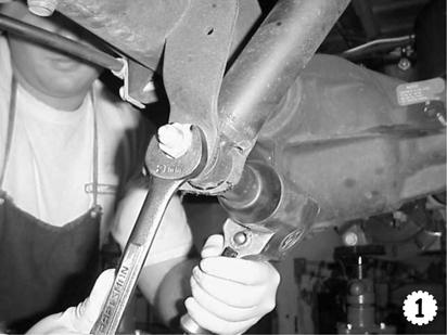
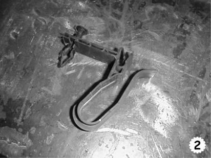
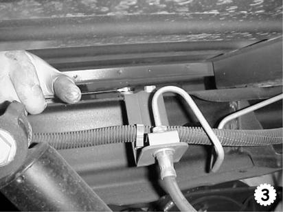
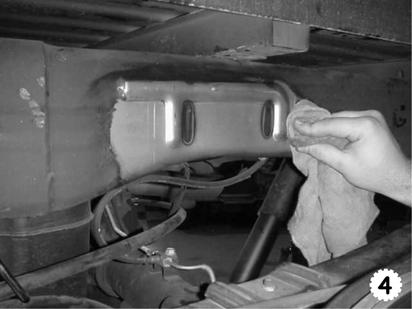
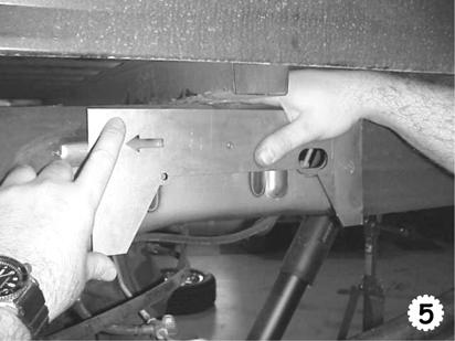
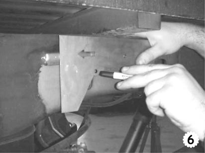
3 e) Slowly lower the vehicle onto the stands and, before placing the vehicle s weight on them, again check that they properly and securely contact the frame rails as described above. Check for possible interference with any lines, wires, or cables. f) Remove the rear wheels from the vehicle. SAFETY REMINDER: Check for safe vehicle stability before proceeding under the vehicle to begin the following procedures. Never work under a vehicle supported by only a jack. Always use properly rated support stands to support the vehicle. g) On Step side models, remove the rear inner-fender liners from the vehicle. h) Using the floor jack located directly below the differential, lift the axle housing just enough to remove a significant portion of the axle load from the leaf springs. This step is required to minimize the load applied to frame rails during notching operations. BE CAREFUL NOT TO LIFT THE VEHICLE OFF OF THE SUPPORT STANDS. i) Support the axle housing with two (2) additional support stands at this height. Make sure the support stands securely contact the axle housing tubes so that the axle housing cannot fall when detached from leaf springs. j) Remove the rear shock absorbers from the vehicle (Photo 1). Keep the factory hardware for use during re-assembly. 2. FRAME NOTCH SUPPORT (C-SECTION) INSTALLATION LEFT-HAND Due to the design of the included Frame Notch Supports (heretofore referred to as C-sections ), pickup box removal is not required with this kit. However, some installers may prefer to remove the box to facilitate access to the frame. If it is decided to remove the vehicle s bed assembly, please refer to the appropriate General Motors Service Manual for recommendations regarding Pickup Box Removal Procedures. Safety Reminder: Proper use of safety equipment and eye/face/hand protection is absolutely necessary when performing the following procedures! a) Working from the LH rear wheel opening, remove the small plastic clip (Photo 2), which secures the rear brake line and wiring harness to the top of the frame rail. This is accomplished by removing the small rivet from its mounting hole. The clip is located on the top of the LH frame rail just rearward of the fuel tank. This clip will not be reused.! To avoid chassis damage, perform the following procedures to only ONE frame rail at a time. b) Remove the rear brake line bracket from the top of the driver s side (LH) frame rail (Photo 3) by removing two hex-head sheet metal screws using a 13mm wrench. The bracket is located above and just behind the rear axle. To avoid damage, temporarily secure the rear brake line, bracket and brake hose, away from the frame rail, using zip ties or elastic straps secured to the rear axle housing or frame cross-member. c) Remove factory jounce stop by loosening and removing the attachment nut, located within the frame rail internal support, using a 15mm wrench. d) Clean frame rail area (Photo 4) with solvent to remove the factory coating. CAUTION: Do not use flammable solvents around sparks or open flames. e) Using the supplied steel template, align slot in template with the slot located on the LH frame rail above and just behind rear axle housing (Photo 5). Also, align the top and bottom edges of the template parallel with the frame rail edges. Be sure that the arrow is pointing forward (towards front of truck). If necessary, fasten template to frame rail using clamps.! It is very important that the template be positioned exactly as shown/described, so that the C- Section Assembly fits over the frame rail properly. Check for proper alignment PRIOR to cutting frame! Also, be aware that this template properly aligns the C-Section notch with the axle ONLY WHEN using the stock leaf springs, hangers, shackles, and other stock components. f) Using a felt tipped pen, mark the exact shape of the C-Notch opening onto the outside face of the LH frame rail (Photo 6).
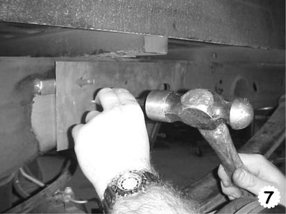
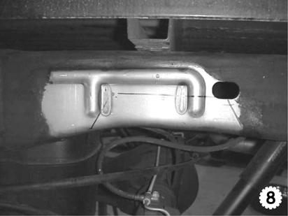
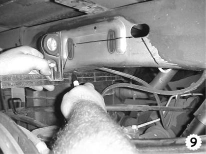
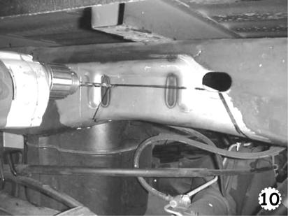
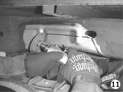
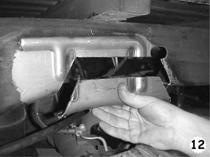
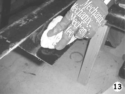
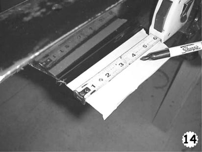
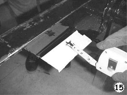
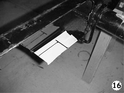
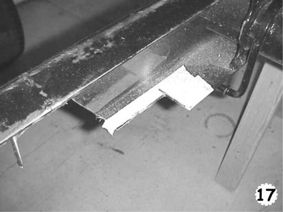
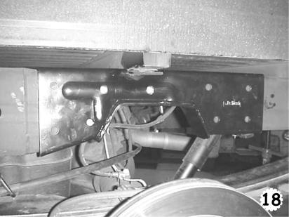
4 g) Using a center punch, mark the center location of the 1/4 hole, provided on the template, as shown (Photo 7). This hole is made so that there will be a round corner at the intersection of the cuts. This will eliminate the possibility of cracks forming at the intersections of the cuts. The rear corner of the C-notch cut intersects within the slot; therefore NO hole is required there. h) Remove the template. Extend marked lines in places covered by template (Photo 8). i) Using a steel square, transfer and mark the lower corners of the C-notch opening, perpendicular to outer face of frame rail, back to underside portion of frame rail (Photo 9). Be sure the lines are perpendicular (90 degrees) to outer face of frame rail. j) IMPORTANT NOTE: Gasoline fumes are extremely explosive. Check to make sure the fuel tank cap is properly installed and secured, and that the fuel tank is fully sealed.! Check the backside of the frame rail to be sure that all lines, electrical wiring, control cables and other components are cleared from this area to avoid damaging them in the following steps. Be sure to wear proper safety protection when using power tools! DO NOT create sparks near flammable or explosive materials. k) Using the drill motor equipped with a ¼ drill bit, drill a hole through frame centered on the mark made above in Step 3g (Photo 10). l) With the frame properly supported as described above, use the die-grinder equipped with a cutoff wheel to cut the C-Notch opening along the scribed lines (Photos 11 & 12). Use the forward ¼ hole, drilled in Step 3k above, to form the front C-Notch corner. If required, a reciprocating saw may be used to cut through the internal OEM jounce-stop re-enforcement.! Be careful when cutting the frame rail. DO NOT remove any material from the frame rail that is not shown/described here. Be careful not to damage any lines or other components located behind the frame rail. Avoid creating any sharp corners or other defects that may cause unnecessary stress-concentrated areas in the frame rail. Avoid overheating frame rail. Safety Recommendation: Due to the close proximity of fuel tank to this area, we DO NOT recommend using a flame-cutting torch or plasma cutter when performing these operations. Also, excess heat can easily damage the frame rail and other adjoining components.! Some care should be taken when cutting through the center portion of the C-Notch, as the factory jounce stop reinforcement bracket is located within the frame rail in this area. Secondary cutting may be required from the inside of the frame rail to remove any portion of this bracket that might interfere with subsequent C-Section installation. m) This Step is required only for vehicles using the 6616/6618 kits as described in Table A. An additional notch is required in the lower frame rail flange just behind the C-notch cut out in Step 3l. o Working from the inside of the frame area, use solvent soaked rag to clean coating from the inside upper surface of the lower frame flange (Photo 13). o Using felt tip pen (or scribe) and tape measure, mark out a line, parallel to rear C- o Notch cut made in Step 3l above, 3 ½ back towards rear of vehicle (Photo 14). Mark out a line, parallel to inner edge of frame rail flange, 1 ¼ towards inner area of frame rail (Photo 15). Photo 16 shows the proper notch layout. o Again using the die-grinder equipped with cut-off wheel cut the notch as shown. Photo 17 shows the completed RH cut. n) Deburr all freshly cut edges using hand file or grinder. o) Paint all bare metal surfaces and edges to prevent rust. p) Install the outer C-section shell over the frame rail, aligning C-notch Support portion with the C- notch cut made in frame rail. Make sure the C-section fits properly over the frame rail and that all profiles align correctly (Photo 18). Check that the support is properly aligned such that the
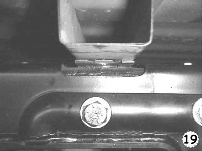
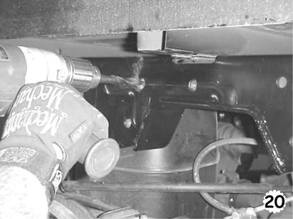
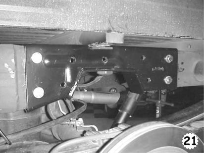
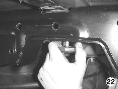
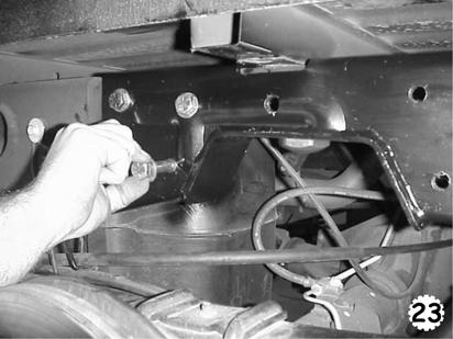
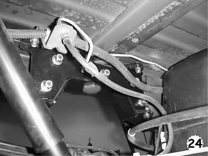
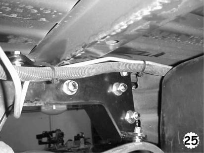
5 square notch, located in the top surface of the C-section, is evenly aligned with central bed cross-member (Photo 19).! It may be necessary to use a soft-faced hammer to position the C-Section shell over frame rail. Make sure the C-section is properly installed prior to proceeding with following hole-drilling procedures. q) With the C-section installed tightly against the outside face of frame rail, use the drill motor, equipped with a 1/2 drill bit, to transfer the nine (9) ½ holes to the frame rail. Use the C- section holes to locate the drill bit (Photo 20). Use cutting lubricant or light oil to facilitate the drilling and to extend drill bit life. To prevent movement while drilling, use C-clamps to fix the C-section shell to the frame rail. Be careful not to damage any lines or other components located behind the frame rail.! Be cautious when drilling these holes, as the fuel tank is located directly behind this area (LH only). While drilling, we highly recommend placing a protective metal plate in the fuel tank area to prevent puncture and/or other damage. r) Working from the outside of the frame rail, insert four (4) ½-20 x 1 ¼ (shorter) hex head bolts with washers into the two most forward and two most rearward holes (Photo 21). Secure these bolts with washers and locknuts. These four (4) nuts/washers should directly contact the inner surface of frame rail. Tighten and torque these bolts to 110 lb ft.! It is important that these shorter, outermost bolts be installed and tightened PRIOR to internal stiffener installation procedures (below), as the forward holes cannot be accessed after stiffener is in position. Follow these instructions exactly as the bolt installation sequence is VERY IMPORTANT! s) Install the kit-supplied urethane jounce stop to the C-notch portion of the C-section shell with supplied locknut (Photo 22). It may be necessary to bend the rearward ear of the internal factory jounce stop reinforcement bracket (cut in Step 3l above) forward to clear the replacement jounce stop stud and nut.! The jounce stop must be installed PRIOR to stiffener plate installation below. t) Insert five (5) ½-20 x 3 ½ (longer) hex head bolts with washers, from outside and through the remaining holes drilled in Step 3q (Photo 23). u) From the inside of the frame rail, install five (5) tubular spacers over the threaded-ends of these bolts. Position the brake line and electrical wiring harness so that they route outside of frame rail and Internal Stiffener. Zip-tie wiring harness to brake line as shown (Photo 24). Be sure that none of these components are pinched or damaged by the hardware. v) Locate the LH C-section Internal Stiffener inside the C-section shell so that the five (5) bolts pass through the appropriate holes and the tubular spacers are located between the frame rail and internal Stiffener (Photo 25). The tabs on the Stiffener should point towards the inside of the vehicle, so that they align with the tabs on the C-section shell.! Make sure the five (5) bolt spacers are sandwiched between the inside portion of frame rail and the C- section stiffener. w) Loosely secure the five (5) bolts, installed in Step 3t, with washers and locknuts but DO NOT TIGHTEN until instructed to below. x) Adjust the C-section stiffener position until the remaining five (5) holes and tabs align with the corresponding holes in the C-section shell. It may be necessary to bend some of the stiffener plate tabs slightly to align with the corresponding tabs of C-section shell. In some cases it may be necessary to enlarge one or more holes slightly using the die-grinder or round file to achieve proper alignment.
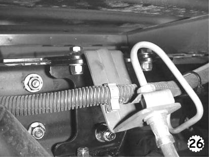
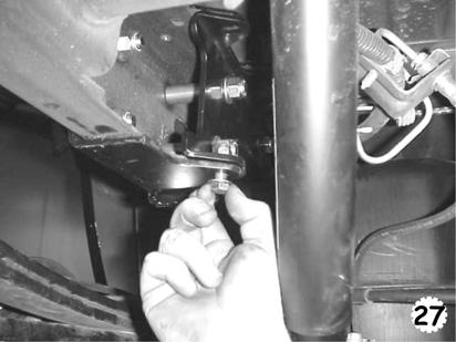
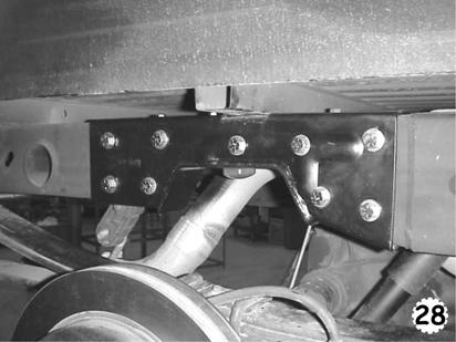
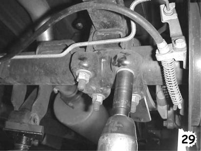
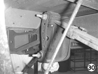
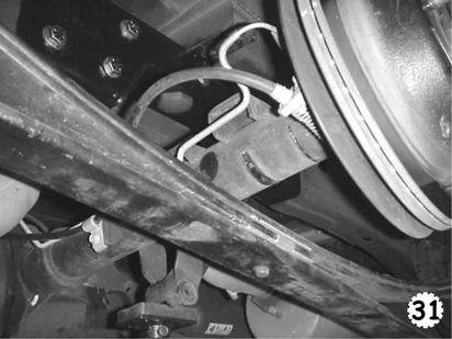
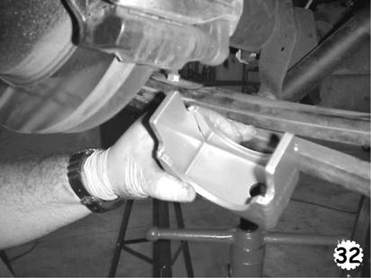
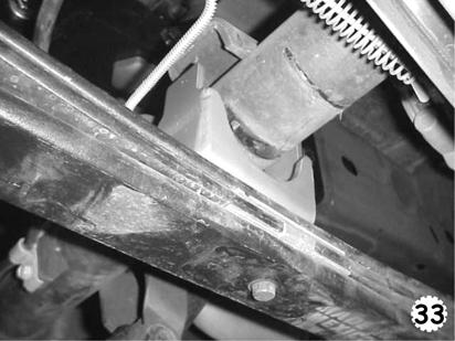
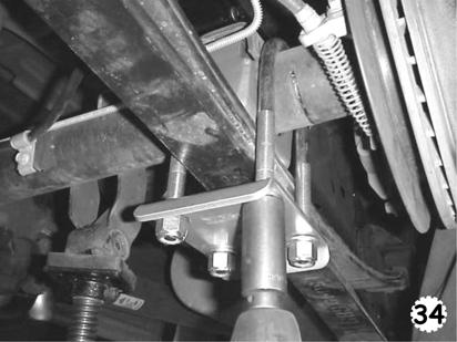
6 y) Install two (2) 3/8-24 x 1 H.H.C.S. (bolts) with washers through the top two forward holes of the C-section shell and then through the tabs of the Internal Stiffener. z) Install one (1) 3/8-24 x 1 H.H.C.S. first through the factory rear brake line bracket (removed in Step 3b), then through the rearward most top bolt hole of the C-section and finally through the rear Stiffener tab (Photo 26). NOTE: The hole in the OEM bracket might need to be enlarged slightly using a round file. aa) Secure the three (3) bolts with washers and locknuts but DO NOT TIGHTEN until instructed to below. bb) Install two (2) 3/8-24 x 1 H.H.C.S. through the lower two holes of the C-section shell and then through the tabs of the Internal Stiffener (Photo 27) from the bottom. Secure with washers and locknuts but DO NOT TIGHTEN until instructed to below. cc) Tighten and torque the five (5) ½ bolts and locknuts installed in Step 3t & 3w to 110 lb ft. dd) Tighten and torque the five (5) 3/8 bolts and locknuts installed in Step 3y, 3z, 3bb, & 3cc to 45 lb ft. 3. FRAME NOTCH SUPPORT (C-SECTION) INSTALLATION RIGHT-HAND a) Repeat Steps 3a through 3dd for passenger s side (RH) of vehicle. Note: the brake line and fuel tank Steps are not applicable for the RH side. Be sure to have the LH side fully installed prior to beginning RH side C-section installation. The completed installation should appear as shown (Photo 28). 4. LEAF SPRING REMOVAL AND RE-INSTALLATION a) With rear axle assembly properly supported, loosen and remove the U-bolt nuts from both sides of axle. Remove the U-bolts, U-bolt locator plates, and axle clamps from the axle tubes (Photo 29). These parts will not be reused. NOTE: Leaf springs may be under tension. Springs under tension store a great amount of energy. USE CAUTION during the following steps to avoid personal injury and/or damage to the vehicle. Be careful not to damage the brake hoses and/or driveline while re-locating rear axle assembly. b) Using the floor jack, adjust the height of the rear axle housing to remove weight from the leaf springs to allow for easy removal of the spring and shackle bolts. c) Loosen and remove the mounting bolts from the front spring hangers and the bottom of the rear shackles (Photo 30). Loosen, but do not remove, the shackles from the springs. d) Mark the leaf springs Left and Right. Also mark each forward spring end with a forward pointing arrow so that the springs can be properly re-installed into their original locations. e) Carefully remove the leaf springs from their mounting locations. f) Using the floor jack, lift the rear axle assembly so that the leaf springs will fit under it. g) Place the leaf springs under the axle in the location and orientation removed (Photo 31). h) Attach the front spring eye into its location in the front spring hanger using the original hardware. Lift the rear of the leaf springs up so that shackles fit into rear spring hangers. Attach using original hardware. DO NOT tighten and torque to final specification until instructed to below. i) Locate the Belltech axle Adapter Saddles supplied in the kit. Place the Adapter Saddles on top of the springs with the hole over the head of the spring center bolt. To properly position the axle, the offset holes MUST be oriented toward the front of the vehicle (Photo 32). Slowly lower the rear axle assembly down onto the saddles. The ears should fit into the stock spring perches on the axle tubes (Photo 33). Make sure both ears on each saddle locate completely into the perches. j) Install the four (4) new U-bolts, 2 per spring, over the axle tubes on each side of the leaf spring packs with threaded ends pointing down. Install the new U-bolts plates below the leaf springs; offset holes forward, so that the U-bolts pass through the appropriate slots (Photo 34). Attach the U-bolt plates using washers and locknuts. Tighten and torque locknuts to 90 lb ft.
7 ! The axle adapter saddles have been design to properly position the rear axle pinion shaft relative to the driveline so that vibrations are eliminated. If driveline vibrations are experienced, take vehicle to driveline service shop immediately for driveline angle inspection and necessary adjustments. DO NOT drive vehicles exhibiting driveline vibrations, as U-joint wear could occur prematurely. Be sure to lubricate the U-joints if deemed necessary. k) Torque spring front hanger nut to 92 lb ft. Torque shackle to frame bracket and shackle to spring nuts to 70 lb ft. 5. SHOCK ABSORBER AND EXTENSION INSTALLATION a) Install Shock Absorber Extensions (P/N 6654) as described in the instructions (these instructions are included separately). b) Install the appropriate Belltech Nitro-Drop or Nitro-Active rear shock absorbers using the original hardware. See the current Belltech Application Guide or contact you nearest Belltech Dealer for the appropriate part numbers for your application. Tighten and torque hardware to 70 lb ft. 6. BED CROSS-MEMBER C-NOTCH INSTALLATION a) Install the Bed Cross-member C-notch (P/N 6655) as described in the instructions (these instructions are included separately).! The Bed Cross-member C-notch Assembly helps to prevent the center-section of the rear axle housing from coming in contact with the underside of the bed. It also strengthens the central area of the bed so that loads can be carried while reducing the possibility of damage occurring to the bed floor. 7. CENTER-CARRIER BEARING RE-LOCATOR INSTALLATION(EXTENDED CAB MODELS ONLY)! The Center Carrier Bearing Adjuster assembly allows adjustments to be made to both the horizontal and vertical positions of the center-carrier bearing on Extended Cab models. These adjustments help to eliminate driveline vibrations. a) Install and adjust the Center-Carrier Bearing Adjustment Assembly (P/N 4995) as described in the instructions (these instructions are included separately).! Due to installation variables and factory manufacturing variances beyond our control, we HIGHLY RECOMMEND that the driveline angles present in the vehicle after modification be checked and compared to the driveline angles present before modification and, if necessary, be brought back within factory specifications. Installation of shims and/or center-carrier bearing adjustments may be required. 8. FINALIZING THE INSTALLATION a) On Step side models, replace the rear inner-fender liners. b) Re-install wheels and torque to the Manufacturer s specifications. c) Check that all components and fasteners have been properly installed, tightened and torqued. d) Lift vehicle and remove support stands. Carefully lower vehicle to ground. e) Check brake hoses, cables and other components for any possible interference. f) If necessary, check driveline angles as described above. g) Check for wheel/tire to chassis/body interference. h) Immediately test-drive the vehicle in a remote location so that you can become accustomed to the revised driving characteristics and handling. Be aware that the vehicle will handle substantially different now that it has been lowered. i) Take the vehicle to a qualified shop for 4-wheel alignment.
8 j) Check all of the hardware and re-torque at intervals for the first 10, 100, and 1000 miles.! The front of the vehicle MUST be lowered accordingly for proper handling and performance and also to maintain warranty. See the current Belltech Application Guide or contact you nearest Belltech Dealer for the appropriate part numbers for your application. Parts List: 6612/6614 & 6616/6618 GMT800 Rear Axle Flip Kit Part # Description Quantity LH C-Section Frame Support (6612/6614 Only) RH C-Section Frame Support (6612/6614 Only) LH C-Section Stiffener (6612/6614 Only) RH C-Section Stiffener (6612/6614 Only) C-section Bolt Spacer Axle Adapter Saddle U-Bolt 5/ /8-18 Locknut /8 Washer A U-Bolt Plate ½-20 x 3 ¾ H.H.C.S. Grade ½-20 x 1 ¼ H.H.C.S. Grade ½-20 Locknut ½ AN Washer /8-24 x 1 H.H.C.S. Grade /8-24 Locknut /8 AN Washer Bump Stop Zip-Tie Shock Extension Assy C.C.B. Adjuster Assy. (6614 Ext. Cab only) Installation Template C-section C-Section LH (6616/6618 Only) C-Section RH (6616/6618 Only) C-Section Frame Stiffener LH (6616/6618 Only) C-Section Frame Stiffener RH (6616/6618 Only) 1
9
10
11
12
13
INSTALLATION INSTRUCTIONS
 INSTALLATION INSTRUCTIONS 6523 & 6524 C-NOTCH KIT 07&UP CHEVROLET SILVERADO / GMC SIERRA 1500 REQUIRES MODIFIED EXHAUST Thank you for being selective enough to choose our high quality BELLTECH PRODUCT.
INSTALLATION INSTRUCTIONS
 INSTALLATION INSTRUCTIONS --300 W PONTIAC WAY CLOVIS, CA 93612 local: 559-875-0222 fax: 559-876-2249 toll free: 800-445-3767-- 6446 5.5 REAR AXLE FLIP-KIT 2015+ FORD F-150 2WD SHORT BED Thank you for being
INSTALLATION INSTRUCTIONS
 INSTALLATION INSTRUCTIONS ----3300 W. Pontiac Way Clovis, CA 93612 toll free: 1-800-445-3767 web: www.belltech.com---- 6686 REAR AXLE FLIP-KIT 2004 DODGE RAM REGULAR CAB, QUAD CAB Thank you for being selective
INSTALLATION INSTRUCTIONS
 INSTALLATION INSTRUCTIONS 6525 REAR AXLE FLIP & HANGER KIT 5 OR 6 INCH LOWERING 14&UP CHEVROLET SILVERADO / GMC SIERRA 1500 Thank you for being selective enough to choose our high quality BELLTECH PRODUCT.
INSTALLATION INSTRUCTIONS
 INSTALLATION INSTRUCTIONS --1075 North Ave. Sanger, CA 93657-3539 local: 559-875-0222 fax: 559-876-2259 toll free: 800-445-3767-- 6522 REAR AXLE FLIP & SHACKLE KIT 07-UP CHEVROLET 1500 REGULAR CAB ONLY
INSTALLATION INSTRUCTIONS
 INSTALLATION INSTRUCTIONS --1075 North Ave. Sanger, CA 93657-3539 local: 559-875-0222 fax: 559-876-2259 toll free: 800-445-3767-- 5317 & 5318 4 INCH REAR LOWERING KIT 09&UP DODGE RAM 1500 2WD Thank you
INSTALLATION INSTRUCTIONS
 INSTALLATION INSTRUCTIONS ----1075 North Ave. Sanger, CA 93657-3539 toll free: 800-445-3767 web: www.belltechcorp.com---- 6419 HANGER & SHACKLE KIT FORD F-150 Congratulations! You were selective enough
INSTALLATION INSTRUCTIONS
 INSTALLATION INSTRUCTIONS ----3300 W. Pontiac Way Clovis, CA 93612 toll free: 1-800-445-3767 web: www.belltech.com---- 6605-6607 FLIP KIT CHEVROLET C/K 1500 / 2500 PICK UP Thank you for being selective
INSTALLATION INSTRUCTIONS
 INSTALLATION INSTRUCTIONS ----1075 North Ave. Sanger, CA 93657-3539 toll free: 800-445-3767 web: www.belltechcorp.com---- 6592 REAR HANGER & SHACKLE KIT DODGE RAM 2500 / 3500 Congratulations! You were
INSTALLATION INSTRUCTIONS
 INSTALLATION INSTRUCTIONS ----1075 North Ave. Sanger, CA 93657-3539 toll free: 800-445-3767 web: www.belltechcorp.com---- 6636 HANGER and SHACKLE KIT 95 99 CHEVY TAHOE / GMC YUKON Congratulations! You
INSTALLATION INSTRUCTIONS
 INSTALLATION INSTRUCTIONS --1075 North Ave. Sanger, CA 93657-3539 local: 559-875-0222 fax: 559-876-2259 toll free: 800-445-3767-- 2505 Lowering Spindle Assembly Installation Instructions ½ TON SILVERADO
INSTALLATION INSTRUCTIONS
 INSTALLATION INSTRUCTIONS ----1075 North Ave. Sanger, CA 93657-3539 toll free: 800-445-3767 web: www.belltechcorp.com---- 6570 SPRING HANGER KIT DODGE DAKOTA Congratulations! You were selective enough
INSTALLATION INSTRUCTIONS
 INSTALLATION INSTRUCTIONS ----1075 North Ave. Sanger, CA 93657-3539 toll free: 800-445-3767 web: www.belltechcorp.com---- 6907 REAR LOWERING KIT 97-00 CHEVY 1-TON C-3500 Congratulations! You were selective
INSTALLATION INSTRUCTIONS
 INSTALLATION INSTRUCTIONS ----3300 W. Pontiac Way Clovis, CA 93612 toll free: 1-800-445-3767 web: www.belltech.com---- 4985 DRIVE LINE SPACER INSTALLATION INSTRUCTIONS Thank you for being selective enough
INSTALLATION INSTRUCTIONS
 INSTALLATION INSTRUCTIONS 2102 LOWERING SPINDLE ASSEMBLY 1998-UP CHEVROLET / GMC BLAZER / X-TREME / JIMMY / ENVOY 2 Wheel Drive Congratulations! You were selective enough to choose a BELLTECH PRODUCT.
INSTALLATION INSTRUCTIONS
 INSTALLATION INSTRUCTIONS ----3300 W. Pontiac Way Clovis, CA 93612 toll free: 1-800-445-3767 web: www.belltech.com---- 4809 2 DROP SPRING KIT Nissan Titan 05+ Thank you for being selective enough to choose
INSTALLATION INSTRUCTIONS
 INSTALLATION INSTRUCTIONS --1075 North Ave. Sanger, CA 93657-3539 local: 559-875-0222 fax: 559-876-2259 toll free: 800-445-3767-- 2000 1984 1991 Toyota 2 Wheel Drive Pick-Ups 2 Front Dropped Spindles Congratulations!
INSTALLATION INSTRUCTIONS
 INSTALLATION INSTRUCTIONS --300 W PONTIAC WAY CLOVIS, CA 93612 local: 559-875-0222 fax: 559-876-2249 toll free: 800-445-3767-- 25007 LIFT / LOWERING STRUT 2015+ FORD F-150 2WD (+1 to -3 ) 2015+ FORD F-150
INSTALLATION INSTRUCTIONS
 INSTALLATION INSTRUCTIONS ----1075 North Ave. Sanger, CA 93657-3539 toll free: 800-445-3767 web: www.belltechcorp.com---- 5052 AIR JACK 94-99 DODGE ½ TON RAM C-1500 Congratulations! You were selective
INSTALLATION INSTRUCTIONS
 INSTALLATION INSTRUCTIONS ----1075 North Ave. Sanger, CA 93657-3539 toll free: 800-445-3767 web: www.belltechcorp.com---- 6420 SHACKLE & HANGER KIT FORD F-350 Congratulations! You were selective enough
INSTALLATION INSTRUCTIONS
 INSTALLATION INSTRUCTIONS --1075 North Ave. Sanger, CA 93657-3539 local: 559-875-0222 fax: 559-876-2259 toll free: 800-445-3767-- 2509 2 DROP SPINDLE 2WD 4WD AWD >>> Must Use 17 Wheels or larger
INSTALLATION INSTRUCTIONS
 INSTALLATION INSTRUCTIONS --1075 North Ave. Sanger, CA 93657-3539 local: 559-875-0222 fax: 559-876-2259 toll free: 800-445-3767-- 5547 REAR ANTI-SWAY BAR 1997-03 FORD F-150 Crew Cab, Harley Edition, &
INSTALLATION INSTRUCTIONS
 INSTALLATION INSTRUCTIONS ----1075 North Ave. Sanger, CA 93657-3539 toll free: 800-445-3767 web: www.belltechcorp.com---- 5001 AIRJACK AIR SPRING SUSPENSION SYSTEM C 1500 AND C-2500 Congratulations! You
INSTALLATION INSTRUCTIONS
 INSTALLATION INSTRUCTIONS 2351 2 DROP SPINDLE 2WD ONLY >>> CANNOT USE STOCK WHEELS you MUST use 20 wheels or larger see instructions on pg. 3
5481 FRONT ANTI-SWAY BAR 10+ CHEVROLET CAMARO
 INSTALLATION INSTRUCTIONS 5481 FRONT ANTI-SWAY BAR 10+ CHEVROLET CAMARO CONGRATULATIONS! You were selective enough to choose a BELLTECH PRODUCT. We have spent many hours developing our line of products
INSTALLATION INSTRUCTIONS
 INSTALLATION INSTRUCTIONS --1075 North Ave. Sanger, CA 93657-3539 local: 559-875-0222 fax: 559-876-2259 toll free: 800-445-3767-- 2511 2 DROP SPINDLE 2WD (Must Use 17 or larger wheels AND be used for 3+
INSTALLATION INSTRUCTIONS
 INSTALLATION INSTRUCTIONS --1075 North Ave. Sanger, CA 93657-3539 local: 559-875-0222 fax: 559-876-2259 toll free: 800-445-3767-- 2103 FRONT DROP BALL JOINT INSTALLATION INSTRUCTIONS CHEVY COLORADO Congratulations!
INSTALLATION INSTRUCTIONS
 INSTALLATION INSTRUCTIONS 2005 2010 DROPPED SPINDLE DATSUN 720 2 WHEEL DRIVE PICK-UPS NISSAN HARDBODY 2WD PICK-UPS Congratulations! You were selective enough to choose a BELLTECH PRODUCT. We have spent
INSTALLATION INSTRUCTIONS
 INSTALLATION INSTRUCTIONS 1075 North Ave. Sanger, CA 93657-3539 local: 559-875-0222 fax: 559-876-2259 toll free: 800-445-3767 2350 2 DROP SPINDLE 2WD (Must Use 18 Wheels or larger see instructions on Pg.
INSTALLATION INSTRUCTIONS
 INSTALLATION INSTRUCTIONS 1075 North Ave. Sanger, CA 93657-3539 local: 559-875-0222 fax: 559-876-2259 toll free: 800-445-3767 av1075 North Ave Sanger, CA 93657-3539 local: 559-875-8883 fax: 559-875-9883
25011 ADJUSTABLE STRUT GMC ENVOY & TRAILBLAZER RAISING AND LOWERING STRUT
 INSTALLATION INSTRUCTIONS 1075 North Ave. Sanger, CA 93657-3539 local: 559-875-0222 fax: 559-876-2259 toll free: 800-445-3767 25011 ADJUSTABLE STRUT 02-07 GMC ENVOY & TRAILBLAZER RAISING AND LOWERING STRUT
INSTALLATION INSTRUCTIONS
 INSTALLATION INSTRUCTIONS 1075 North Ave. Sanger, CA 93657-3539 local: 559-875-0222 fax: 559-876-2259 toll free: 800-445-3767 3100-3200 3 DROPPED FRONT SPINDLE 73-87 1/2 TON C-10 PICK-UP / 1/2 TON BLAZER
PRO COIL INSTALLATION
 INSTALLATION INSTRUCTIONS 1075 North Ave. Sanger, CA 93657-3539 local: 559-875-0222 fax: 559-876-2259 toll free: 800-445-3767 12463-12464 PRO COIL INSTALLATION 2007 IMPORTANT NOTE THIS KIT GIVES YOU THE
INSTALLATION INSTRUCTIONS
 INSTALLATION INSTRUCTIONS 2100 DROPPED FRONT SPINDLE CHEVROLET 2WD S-10 / S-15 PICKUP / BLAZER / JIMMY, including models with ABS General Motors G-Body Rear Wheel Drive Cars CONGRATULATIONS! You were selective
INSTALLATION INSTRUCTIONS 88518
 INSTALLATION INSTRUCTIONS 88518 For Rancho Suspension Systems RS6518: 2009 FORD F-150 4WD READ ALL INSTRUCTIONS THOROUGHLY FROM START TO FINISH BEFORE BEGINNING INSTALLATION Rev A IMPORTANT NOTES! WARNING:
Super Duty Front Air Bag Installation Instructions
 2005-2010 Super Duty Front Air Bag Installation Instructions Congratulations! You have just purchased the best engineered, highest quality front air suspension kit available on the market for your 2005-2010
Suspension System RS6582B
 Suspension System RS6582B Tahoe/Yukon READ ALL INSTRUCTIONS THOROUGHLY FROM START TO FINISH BEFORE BEGINNING INSTALLATION IMPORTANT NOTES! WARNING: This suspension system will enhance the off-road performance
Toyota Tundra Tow Kit Installation Instructions
 2007-2013 Toyota Tundra Tow Kit Installation Instructions Congratulations! You have just purchased the best engineered, highest quality air suspension kit available on the market for your 07-14 Toyota
INSTALLATION INSTRUCTION 88148
 INSTALLATION INSTRUCTION 88148 Rev C For Rancho Suspension Systems RS6548, RS6549 & RS6550: GM 2500HD, 2500, and 1500HD Trucks READ ALL INSTRUCTIONS THOROUGHLY FROM START TO FINISH BEFORE BEGINNING INSTALLATION
Installation Instructions
 Equipment Required: Installation Instructions Fastener Kit: F Wrenches: 8mm, 13mm, 3/4, 15/16 Drill Bits: 1/4 Other Tools: Drill, Reciprocating Saw, File WARNING: Under no circumstances do we recommend
INSTALLATION INSTRUCTION 88088
 INSTALLATION INSTRUCTION 88088 For Rancho Suspension Systems RS6588 & RS6589: FORD F-150 READ ALL INSTRUCTIONS THOROUGHLY FROM START TO FINISH BEFORE BEGINNING INSTALLATION Rev B IMPORTANT NOTES! WARNING:
Installation Instructions
 Equipment Required: Installation Instructions Fastener Kit: F Wrenches: 8mm, 13mm, 3/4, 15/16 Drill Bits: 1/4 Other Tools: Drill, Reciprocating Saw, File WARNING: Under no circumstances do we recommend
INSTALLATION INSTRUCTIONS
 INSTALLATION INSTRUCTIONS 2500 DROPPED FRONT SPINDLE CHEVROLET C / K and G.M.C. SIERRA 1500 / 2500 / 3500 Pick-Ups Congratulations! You were selective enough to choose a BELLTECH PRODUCT. We have spent
Detroit Speed, Inc. Mini-Tub Kit Chevy Nova, Oldsmobile Omega, Pontiac Ventura P/N: &
 Detroit Speed, Inc. Mini-Tub Kit 1968-74 Chevy Nova, Oldsmobile Omega, Pontiac Ventura P/N: 041207 & 041208 Item Component Quantity 1 DSE Mini Tubs 1968-74 X-Body 2 2 Rear Upper Shock Crossmember 1 3 Upper
Installation Instructions
 Installation Instructions Product: ACOS Pro Part Number: PN 2700 Applications: Jeep Wrangler TJ, 1997-06 (front or rear) Jeep Grand Cherokee ZJ, 1993-98 (front only) Jeep Cherokee XJ, 1984-01 (front only)
80-96 Ford F150 / Bronco 4WD Class II 4"- 6" Suspension Lift Installation Instructions
 www.skyjacker.com Required Tool List: 80-96 Ford F150 / Bronco 4WD Class II 4"- 6" Suspension Lift Installation Instructions Safety Glasses Metric / Standard Wrenches & Sockets Floor Jack Jack Stands Measuring
INSTALLATION INSTRUCTION 88051
 INSTALLATION INSTRUCTION 88051 For Rancho Suspension System RS6551: Chevrolet 2500 Suburban & 2500 Avalanche READ ALL INSTRUCTIONS THOROUGHLY FROM START TO FINISH BEFORE BEGINNING INSTALLATION Rev C IMPORTANT
R4TECH PRODUCT SAFETY NOTICE
 R4TECH PRODUCT SAFETY NOTICE Congratulations. This vehicle has been equipped with an R4Tech suspension system that provides the ride quality of a full-air suspension with the ease of installation of a
82-01 Chevy S-10/ GMC Sonoma Front Kit Part No B
 www.airliftcompany.com 82-01 Chevy S-10/ GMC Sonoma Front Kit Part No. 75512B MN-481 (02105) ECN 3549 Please read these instructions completely before proceeding with installation Left Side Upper Shock
IMPORTANT WARRANTY & INSTALLATION INSTRUCTIONS ATTACHED
 IMPORTANT WARRANTY & INSTALLATION INSTRUCTIONS ATTACHED Please Forward All Attached Information to Consumer Warranty Not Valid Unless Returned to CORSA Exhaust STOP Please take time to read and understand
INSTALLATION INSTRUCTIONS
 INSTALLATION INSTRUCTIONS --1075 North Ave. Sanger, CA 93657-3539 local: 559-875-0222 fax: 559-876-2259 toll free: 800-445 3767 5557 REAR ANTI-SWAY BAR 05-UP NISSAN TITAN CONGRATULATIONS! You were selective
Tools Needed: Class 8.8 Class MM 55ft/lbs 75ft/lbs 14MM 85ft/lbs 120ft/lbs 16MM 130ft/lbs 165ft/lbs 18MM 170ft/lbs 240ft/lbs
 921788000 JEEP JK 6 LONGARM Rough Country recommends a certified technician install this system. In addition to these instructions, professional knowledge of disassemble/reassembly procedures as well as
INSTALLATION INSTRUCTION 88146
 INSTALLATION INSTRUCTION 88146 Rev H FOR RANCHO SUSPENSION SYSTEM RS6547: 4WD SUBURBAN/YUKON XL, 4WD TAHOE/YUKON, & 4WD AVALANCHE READ ALL INSTRUCTIONS THOROUGHLY FROM START TO FINISH BEFORE BEGINNING
TOYOTA HIGHLANDER RUNNING BOARD HIGHLANDER HV Preparation
 Preparation Part Number: PT738-48080 Kit Contents Item # Quantity Reqd. Description 1 1 Driver Side Running Board 2 1 Passenger Side Running Board 3 4 /Middle Mount Bracket 4 2 Rear Mount Bracket 5 2 Rear
Detroit Speed, Inc. Second Generation Camaro/Firebird Mini-Tub Kit Camaro/Firebird P/N: ,
 Detroit Speed, Inc. Second Generation Camaro/Firebird Mini-Tub Kit 1970-1981 Camaro/Firebird P/N: 041222, 041223 The Detroit Speed Second Generation Camaro/Firebird Rear Mini-Tub Kit is designed to accommodate
INSTALLATION INSTRUCTION 88578
 INSTALLATION INSTRUCTION 88578 For Rancho Suspension System RS6579B: 4WD Dodge 1500 & 2500 READ ALL INSTRUCTIONS THOROUGHLY FROM START TO FINISH BEFORE BEGINNING INSTALLATION Rev E IMPORTANT NOTES! WARNING:
JK REAR BUMPER AND TIRE CARRIER
 JK REAR BUMPER AND TIRE CARRIER Installation Guide AEV30105AA (Updated 5/10/10) Page 1 of 20 Page 2 of 20 EXPLODED VIEW PLEASE READ BEFORE YOU START IN ORDER TO INSTALL THIS PART PROPERLY YOU OR YOUR INSTALLER
Installation Instructions
 Equipment Required: Fastener Kit: F Wrenches: 3/4, 15/16 Drill Bits: 1/4 Other Tools: Drill Installation Instructions Short & Long Bed All Megacabs 9464/9474 HIDE-A-GOOSE HITCH INSTALLATION WARNING: Under
Suzuki Samurai to Toyota Front Spring Swap Kit, with Missing Link Shackles (SKU#SSP-TSFM) Installation Instructions
 Installation Instructions") Suzuki Samurai to Toyota Front Spring Swap Kit, with Missing Link Shackles (SKU#SSP-TSFM) Installation Instructions CAUTION: Safety glasses should be worn at all times when working with vehicles and related
Suzuki Samurai to Toyota Front Spring Swap Kit, with Missing Link Shackles (SKU#SSP-TSFM) Installation Instructions CAUTION: Safety glasses should be worn at all times when working with vehicles and related
INSTALLATION GUIDE. JK Rear bumper & tire carrier. AEV30105AC Last Updated: 10/11/16 US PATENT: D642,502 ; D
 AEV30105AC Last Updated: 10/11/16 JK Rear bumper & tire carrier US PATENT: D642,502 ; D633.024 INSTALLATION GUIDE PLEASE READ BEFORE YOU START TO GUARANTEE A QUALITY INSTALLATION, WE RECOMMEND READING
INSTALLATION INSTRUCTION 89400
 INSTALLATION INSTRUCTION 89400 FOR RANCHO SUSPENSION SYSTEM RS66400B: 2012 RAM 1500 4WD. READ ALL INSTRUCTIONS THOROUGHLY FROM START TO FINISH BEFORE BEGINNING INSTALLATION Rev B IMPORTANT NOTES! WARNING:
Installation Instructions
 GOOSENECK MOUNTING KIT Equipment Required: Fastener Kit: F Wrenches: 13mm, 3/4, 7/8, 15/16 Drill Bits: 1/4 Other Tools: Drill WARNING: Under no circumstances do we recommend exceeding the towing vehicle
MODEL 2604 WARNING <THESE INSTRUCTIONS MUST BE GIVEN TO THE END USER> Custom 5th Wheel Hitch Mounting Rail Installation Instructions
 B&W Trailer Hitches 1216 Hawaii Rd / PO Box 186 Humboldt, KS 66748 P:620.473.3664 F:620.869.9031 Custom 5th Wheel Hitch Mounting Rail Installation Instructions
PARTS LIST: 8581 DODGE LONG ARM BRACKETS 03-13
 SYNERGY MFG. 870 INDUSTRIAL WAY, SAN LUIS OBISPO, CA (805) 242-0397 8580 03-12 DODGE 2500/3500 4X4, 06-08 1500 MEGACAB 4X4 LONG ARM SUSPENSION KIT V3.0 GENERAL NOTES: These instructions are also available
INSTALLATION INSTRUCTION 88581
 INSTALLATION INSTRUCTION 88581 FOR RANCHO SUSPENSION SYSTEM RS6581B: DODGE RAM READ ALL INSTRUCTIONS THOROUGHLY FROM START TO FINISH BEFORE BEGINNING INSTALLATION Rev C IMPORTANT NOTES! WARNING: This suspension
<THESE INSTRUCTIONS MUST BE GIVEN TO THE END USER> B&W
 B&W Trailer Hitches 6 Hawaii Rd / PO Box 86 Humboldt, KS 66748 P:60.473664 F:60.869.903 Turnoverball Gooseneck Hitch Installation Instructions MODEL 08
Trike Conversion Installation Guide for Indian Scout Motorcycles 2016 & Up Revision 2
 Trike Conversion Installation Guide for Indian Scout Motorcycles 2016 & Up Revision 2 Warning - This product was not intended for more than one rider. Weight limit on this product has been set at 400 lbs.
HP10033 KIT. * See application guide for proper fitment.
 HP10033 KIT * See application guide for proper fitment. Use the most advanced air springs on the market to eliminate your vehicle s sag, sway and bottoming out. Pacbrake air suspension levels your truck
'99-03 CHEVROLET/GMC IFS 4WD 6" SUSPENSION SYSTEM P/N INSTALLATION INSTRUCTIONS
 1/16/04 '99-03 CHEVROLET/GMC IFS 4WD 6" SUSPENSION SYSTEM P/N. 10-41099 INSTALLATION INSTRUCTIONS NOTE: Each Lift Kit and options to Lift Kits are packaged separately. Therefore, installation procedures
JEEP JK 4 LONGARM. Tools Needed: Thank you for choosing Rough Country for your suspension needs.
 921786000 Thank you for choosing Rough Country for your suspension needs. JEEP JK 4 LONGARM Rough Country recommends a certified technician install this system. In addition to these instructions, professional
INSTALLATION INSTRUCTIONS
 INSTALLATION INSTRUCTIONS 2005-2012 Nissan Xterra/Frontier / Pathfinder PART NUMBERS: NP17500, NP17525, NP17550 FRONTIER PARTS & CORRESPONDING HARDWARE LIST XTERRA PATHFINDER ABOVE LISTED 1/2 Metal Lock
FRONT DRIVELINE MODIFICATION MAY BE NECESSARY!!!!
 INSTALLATION INSTRUCTIONS FOR 2009 DODGE 2500/3500 4WD & 1500 Mega Cab 6 SUSPENSION SYSTEM PART NUMBER 7206 Requires the following parts (sold separately) for a complete installation: Front Coil Spring
Installation Instructions
 Equipment Required: Fastener Kit: F Wrenches: 3/4, 15/16, 10mm, 18mm Drill Bits: 1/4 Other Tools: Drill, Reciprocating saw 9465/9475 HIDE-A-GOOSE HITCH INSTALLATION All Fasteners Typical, Both Sides WARNING:
2013+ DODGE RAM " Kit PART# STOP! READ THIS FIRST!
 NOTE: 2013+ DODGE RAM 3500 4" Kit PART# 54346 STOP! READ THIS FIRST! **READ THESE ENTIRE INSTRUCTIONS BEFORE STARTING ANYTHING** or chroming, which can damage the strength and structure of the metal, any
Sport S/T3 Suspension Installation Guide
 1 Sport S/T3 Suspension Installation Guide #1258250-JK 2-Door Sport S/T3 (No Shocks) #1258200-JK 2-Door Sport S/T3 (w/ Fox Shocks) #1258450-JK 4-Door Sport S/T3 (No Shocks) #1258400-JK 4-Door Sport S/T3
Dodge 5 Lift Kit Thank you for choosing Rough Country Suspension for your Off Road needs.
 *1368BAG4* 1368BAG4 921368200 2014-16 2500 Dodge 5 Lift Kit Thank you for choosing Rough Country Suspension for your Off Road needs. Rough Country recommends a certified technician installs this system.
Ford F-150 4WD 6" Suspension Lift Installation Instructions
 2004-2008 Ford F-150 4WD 6" Suspension Lift Installation Instructions www.skyjacker.com Required Tool List: Safety Glasses Metric / Standard Sockets & Wrenches Spring Compressor Floor Jack Jack Stands
»Product» Safety Warning
 RBP-LK410-40, RBP-LK410-60 RBP-LK411-60, RBP-LK411-40 Installation Instructions 2005-2015 / 2016+ Toyota Tacoma 4" and 6" Lift Systems Read and understand all instructions and warnings prior to installation
JK BFH II Front Bumpers
 INSTALLATION INSTRUCTIONS INST-17-16-021_A JK BFH II Front Bumpers IMPORTANT: Thank you for purchasing this Poison Spyder product. Please read through this entire document before proceeding with installation.
INSTALLATION INSTRUCTION 88092
 INSTALLATION INSTRUCTION 88092 FOR RANCHO SUSPENSION SYSTEM RS6592: NISSAN XTERRA & 2WD FRONTIER READ ALL INSTRUCTIONS THOROUGHLY FROM START TO FINISH BEFORE BEGINNING INSTALLATION Rev C IMPORTANT NOTES!
INSTALLATION INSTRUCTION 88094
 INSTALLATION INSTRUCTION 88094 FOR RANCHO SUSPENSION SYSTEM RS6594B 4WD & 2WD NISSAN TITAN READ ALL INSTRUCTIONS THOROUGHLY FROM START TO FINISH BEFORE BEGINNING INSTALLATION Rev D IMPORTANT NOTES! WARNING:
INSTALLATION INSTRUCTION 88073
 INSTALLATION INSTRUCTION 88073 Rev C FOR RANCHO SUSPENSION SYSTEMS RS6572 & RS6573: DODGE RAM READ ALL INSTRUCTIONS THOROUGHLY FROM START TO FINISH BEFORE BEGINNING INSTALLATION IMPORTANT NOTES! WARNING:
63162K 2015 Chevrolet Colorado 4WD Leveling Kit w/ 1 Rear Lift Kit
 PRO COMP SUSPENSION 63162K 2015 Chevrolet Colorado 4WD Leveling Kit w/ 1 Rear Lift Kit This document contains very important information that includes warranty information and instructions for resolving
Installation Instructions
 Equipment Required: Fastener Kit: F Wrenches: 15/16, 15/16 Crowfoot Adaptor Drill Bits: 1/4 Other Tools: Drill, Reciprocating saw Optional, Raise Bed: 18mm socket, 15 extension As an option you can loosen
Trike Conversion Installation Guide Kawasaki Vulcan 900 Classic, Classic LT, and Custom Models 2007 and Up Solid Axle Suspension
 Trike Conversion Installation Guide Kawasaki Vulcan 900 Classic, Classic LT, and Custom Models 2007 and Up Solid Axle Suspension CAUTION: -Failure to make the proper adjustments will potentially lead to
Detroit Speed, Inc. Detroit Speed Control Arm and Spindle Kit A-Body P/N: &
 Detroit Speed, Inc. Detroit Speed Control Arm and Spindle Kit 1964-72 A-Body P/N: 030104 & 030105 The Detroit Speed A-Body front suspension kit is a bolt-on package that addresses the shortcomings of the
Installation Instructions
 Equipment Required: Fastener Kit: F Wrenches: 15/16, 10 mm Drill Bits: 1/4 Other Tools: Drill, Reciprocating Saw 9464/9474 HIDE-A-GOOSE HITCH All Fasteners Typical, Both Sides WARNING: Under no circumstances
Chevrolet 3100 IFS Kit
 1947-54 Chevrolet 3100 IFS Kit Congratulations on your purchase on what we believe is the finest IFS kit available for 1947-54 Chevrolet pickups with stock frames. We have invested many hours into designing
INSTALLATION INSTRUCTIONS 89551
 INSTALLATION INSTRUCTIONS 89551 For Rancho Suspension System RS66551B: Ford F250, F350 Super Duty 4x4 DIESEL ONLY (Single Rear Wheels Only With or Without Auxiliary Spring). (WILL NOT WORK ON GAS ENGINES
Installation Instructions
 Important Parts Installation Instructions INSTALLATION REQUIRES WELDING by a qualified welder or metal fabricator. Weld-on installation is strongly recommended for maximum strength and reinforcement of
2015+ F-150 Active Exhaust Kit Installation Instructions P/N: (1117-5E292LITE)
") 2015+ F-150 Active Exhaust Kit Installation Instructions P/N: 422104 (1117-5E292LITE) 39555 Schoolcraft Rd, Plymouth MI, 48170 800.59.ROUSH 2015+ Ford F-150 Active Exhaust Kit Installation Instructions
2015+ F-150 Active Exhaust Kit Installation Instructions P/N: 422104 (1117-5E292LITE) 39555 Schoolcraft Rd, Plymouth MI, 48170 800.59.ROUSH 2015+ Ford F-150 Active Exhaust Kit Installation Instructions
04-08 FORD F150 4 KIT
 9257700 04-08 FORD F50 4 KIT THANK YOU FOR CHOOSING ROUGH COUNTRY FOR YOUR SUSPENSION NEEDS. Rough Country recommends a certified technician install this system. In addition to these instructions, professional
INSTALLATION INSTRUCTION Rev A
 INSTALLATION INSTRUCTION 88587 Rev A FOR RANCHO SUSPENSION SYSTEM RS6587B: 2009 DODGE RAM 1500 READ ALL INSTRUCTIONS THOROUGHLY FROM START TO FINISH BEFORE BEGINNING INSTALLATION IMPORTANT NOTES! WARNING:
Kit No Please read these instructions completely before proceeding with installation. Air Spring Kit Parts List. Bracket Attaching Hardware
 Kit No. 59532 MN-572 (021108) ECR 7136 Please read these instructions completely before proceeding with installation Air Spring Kit Parts List A Item Description Quantity A Air Sleeves 2 B Upper Brackets
INSTALLATION INSTRUCTIONS
 Product: Steering Stabilizer Relocation Kit Part Number: JKSOGS900 (JKSOGS162/JKSJSPEC1000/JKSOGS924) INSTALLATION INSTRUCTIONS Applications: Wrangler JK, 2007+ Welcome CONGRATULATIONS on purchasing a
TOYOTA 4-RUNNER KIT 5 KIT
 92173600 1990-1995 TOYOTA 4-RUNNER KIT 5 KIT Thank you for choosing Rough Country for all your suspension needs. Rough Country recommends a certified technician install this system. In addition to these
Installation Instructions
 Installation Instructions Eibach Springs, Inc. 264 Mariah Circle Corona, California 92879-1751 USA Tech Support 800-222-8811 Ext 114 CASTER / CAMBER PLATE KIT # 5.3518K 1999-2004 SN95 Ford Mustang - All
2013+ DODGE RAM LIFT KIT PART# STOP! READ THIS FIRST!
 NOTE: 2013+ DODGE RAM 3500 8 LIFT KIT PART# 54324 STOP! READ THIS FIRST! **READ THESE ENTIRE INSTRUCTIONS BEFORE STARTING ANYTHING** or chroming, which can damage the strength and structure of the metal,
PRE-INSTALLATION. INSTALLATION INSTRUCTIONS STEP 1: Park vehicle on level surface and chock rear wheels.
 2007-2013 7.5" GMC/Chevrolet 1500 4WD Suspension Lift kit PRE-INSTALLATION 15004 2 - Cross-member (Fr/Rr) 2 - Sway Bar Drop Bracket 2 - Knuckle (Dr/Pass) 1 - Driver Diff. Bracket 1 - Passenger Diff. Bracket
Please read these instructions completely before proceeding with installation. Read all maintenance guidelines on page 7 before operating the vehicle.
 MN-643 (02511) ECR 5461 Kit No. 39205 Please read these instructions completely before proceeding with installation Item P/N Description Quantity A 26391 Driver-Side Beam Assembly 1 B 26414 Passenger-Side