UNIT IV DESIGN OF ENERGY STORING ELEMENTS. Prepared by R. Sendil kumar
|
|
|
- Kelley Washington
- 5 years ago
- Views:
Transcription


1 UNIT IV DESIGN OF ENERGY STORING ELEMENTS Prepared by R. Sendil kumar
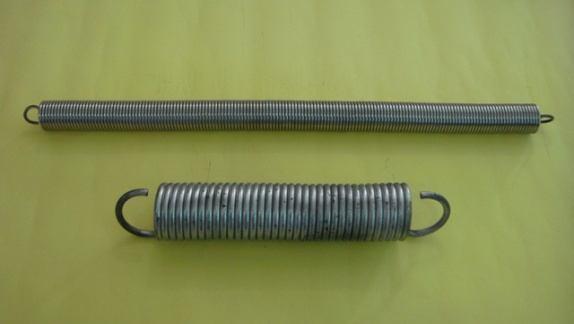
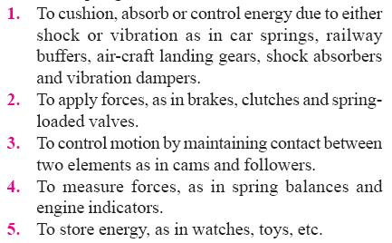
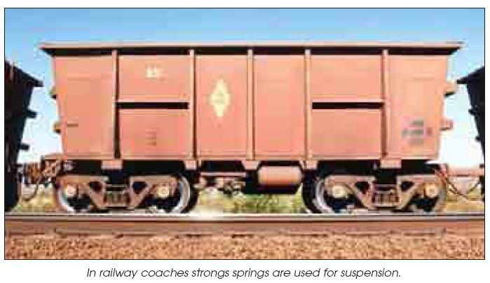
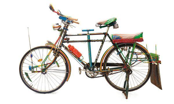
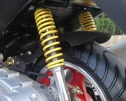
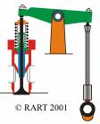
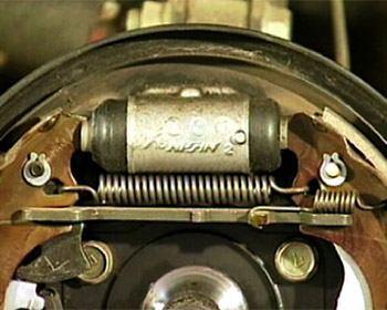
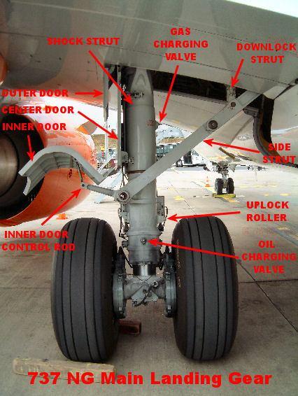
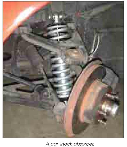
2 SPRINGS: INTRODUCTION Spring is an elastic body whose function is to distort when loaded and to recover its original shape when the load is removed. APPLICATION: 1. To absorb energy suspension systems, shock absorber, etc. 2. To store energy watches, toys, etc. 3. To apply force Brakes, clutches, safety valves etc.
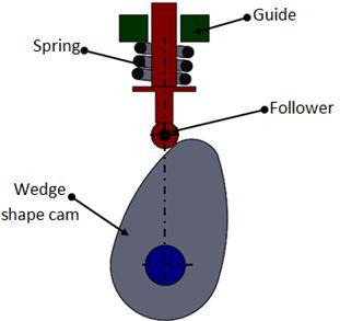
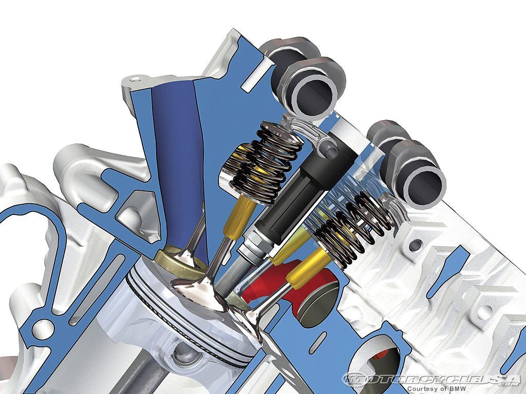
3 Continue 4. To ensure position or contact in Ic engines valves & cam-follower. 5. To accommodate misalignment Joining of railway compartment. SPRING MATERIAL: 1. Oil tempered carbon steel 2. Music wire 3. Phasphor Bronze 4. Beryllium Copper 5. Monel metal 6. Brass
4 Continue TYPES OF SPRING: 1. Helical springs (a) Closed coil spring (b) open coil spring 2. Conical and volute spring 3. Torsion spring 4. Laminated (or)leaf spring 5. Disc (or) Bellevile spring 6. Special purpose spring
5 HELICAL SPRINGS Open coiled Closed coil helical spring helical spring 1. The gap between sucessive Small turns is large

6 2. Helix angle is less than 10º more than 10º 3. It can take up tensile It can take up tensile & compressive load load only 4. Friction effect is less Friction effect is more 2. Conical and volute springs:
 Leaf")
7 3.Torsional spring: 4. Laminated (or) Leaf spring:

8 5. Disc (or) bellevile springs 6. Special purpose spring
9 Classification

10 Types of Springs Helical: Compression Extension Torsion


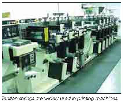
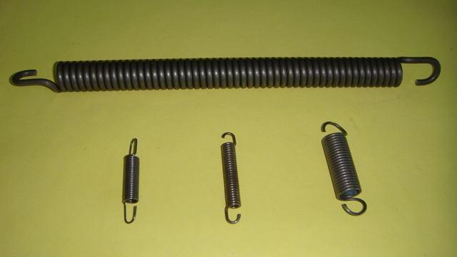
11 SPRING PRODUCTS Tension Spring Compression Spring


12 More Springs Washer Springs: Beams: Power springs:
13 Applications
14

15
16
17
18

19
20
21

22

23

24 PRODUCT APPLICATION Adjuster Spring
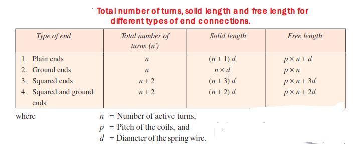
25 TERMS USED IN COMPRESSION SPRING SOLID LENGTH When the compression spring is compressed until the coils come in contact with each other the spring is said to be solid. The solid length of a spring is the product of total number of coils and the diameter of the wire. LS=n d n - total number of coils d- diameter of the wire FREE LENGTH It is the length of the spring in the free or unloaded condition. It is equal to the solid length plus the maximum deflection or compression of the spring and the clearance between the adjacent coils. LF=n d+δmax+0.15 δmax
26 SPRING INDEX It is defined as the ratio of the mean diameter of the coil to the diameter of the coil to the diameter of the wire. C=D/d D- mean diameter of coil d- diameter of wire SPRING RATE It is defined as the load required per unit deflection of the spring. q=w/δ W- applied load δ - deflection of the spring
27 PITCH The pitch of the coil is defined as the axial distance between adjacent coil in uncompressed state. Pitch length=free length/(n -1) Mostly square and ground ends condition is used for compressive spring. n = n+2
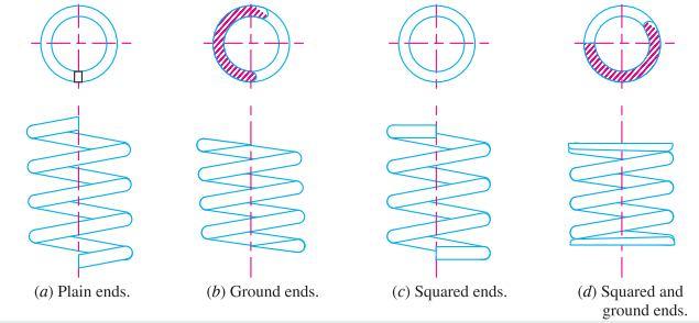
28 ENDS FOR COMPRESSION HELICAL SPRING:
29 End Conditions Plain Plain Ground N a = Active Coils Square Square Ground
30 DESIGN OF HELICAL SPRINGS There are two aspects of design of springs 1. Stress induced 2. Deflection of the spring Stresses induced 1. (a) Direct shear stress (b) Torsional shear stress
31
32
33 The wall factor after the account for the curvature effect Using the above equation, wire diameter is to be found. Deflection of the spring (δ (or) y: δ = 8WD 3 n/gd 4
34 Problems: 1. A helical spring is made from a wire of 6 mm diameter and has outside diameter of 75 mm. If the permissible shear stress is 350 Mpa and modulus of rigidity 84 kn/mm 2, find the axial load which the spring can carry and the deflection per active turn.
35 Continue 2. Design a spring for a balance to measure 0 to 1000 N over a scale of length 80mm. The spring is to be enclosed in a casing of 25 mm diameter. The approximate number of turns is 30. The modulus of rigidity is 85 kn/mm 2. Also calcualte the maximum shear stress induced.
36 Continue 3. A helical compression spring made of oil tempered carbon steel is subjected to a load which varies from 400 N to 1000 N. The spring index is 6 and design factor of safety is If the yield shear stress 770 Mpa and the endurance shear stress is 350 Mpa. (i) Size of the spring wire (ii) Diameter of spring (iii) Number of turns of spring (iv) Free length of spring. The compression spring maximum load 30 mm. Take G = 80 kn/mm 2.

37 Given: Given : D = 50 mm ; d = 5 mm ; *n = 20 ; W = 500 N Solution: Find: Maximum Shear Stress ( ) Spring index Shear stress factor C Maximum Shear stress d D K S C 2 10 PSG 7.100
38 Continue 5. Design a close coiled helical spring of silicon manganese steel for the valve of an IC engine capable of exerting a net force of 65 N when the valve is open and 54 N when the valve is closed. The internal and external diameters are governed by space limitations, as it has to fit over bushing of 19 mm outside diameter and go inside a space of 38 mm diameter. The valve lift is 6 mm. (N/D 2010)
39 6. A helical compression spring made of circular wire is subjected to an axial force, when varies from 2.5 kn to 3.5 kn over this range of forces, the deflection of the spring should be approximately 5mm. The spring index can be taken as 5. The spring has square and ground ends. The spring is made of patterned and cold drawn steel wire and ultimate strength of 1050 N/mm 2 and modulus of rigidity N/mm 2. The permissible shear stress for the spring wire should be taken 50% of the ultimate strength. Find, (i)wire diameter (ii) mean coil diameter (iii) number of active coils (iv) total number of coils (v) solid length of the spring (vi) free length (vii) required spring rate (viii) actual spring rate.
40 7. Design a close coiled helical springs for a service load ranging from 2250 N to 2750 N. The axial deflection of the spring for the load range of 6mm. Assume a spring index of 5. The permissible shear stress intensity is 420 Mpa and modulus of rigidity G = 84 kn/mm 2. Neglect the effect of concentration. Draw a fully dimensioned sketch of the spring. Show spring details the finish end coils.
41 8. Design a helical spring for a spring loaded safety valve (Ramsbottom safety valve) for the following conditions: Diameter of valve seat = 65 mm, operating pressure = 0.7 N/mm 2, maximum pressure when the valve blows off freely = 0.75 N/mm 2, maximum lift of the valve when the pressure rises from 0.7 to 0.75 N/mm 2 = 3.5 mm, maximum allowable stress = 550 Mpa, modulus of rigidity = 84 kn/mm 2, spring Index = 6. Draw a neat sketch of the free spring showing the main dimensions.
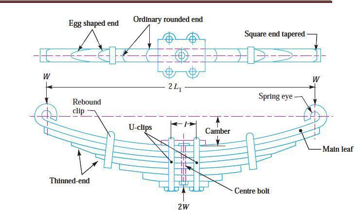
42 Leaf spring It is used in automobile suspension systems. These are called graduated (or) laminated springs, because number of flat plates are stacked together. By geometry they are semielliptical in shapes.
43 Continue
44 Problems: A locomotive semielliptical laminated spring has an overall length of 1m and sustains a load of 70 kn at its centre. The spring has 3 full length leaves and 15 graduated leaves with a central band of 100 mm width. All the leaves are to be stressed to 400 Mpa, when fully loaded. The ratio of the total spring depth to that of width is 2. Take young modulus is 210 kn/mm 2. Determine (i) the thickness and width of the leaves (ii) the initial gap that should be provided between the full length and graduated leaves before the band load is applied and (iii) the load exerted on the bank after the spring is assembled.
45 Continue Design a leaf spring for the following specifications: Total load 140 kn, Number of springs supporting the load = 4, maximum number of leaves 10, span of the spring = 1000 mm, permissible deflection = 80 mm, Take young s modulus (E) = 200kN/mm 2 and allowable stress in the spring material as 600 Mpa.
46 A semi elliptical laminated spring is made of 50 mm wide and 3 mm thick plate. The length between supports is 65 cm and the width of band is 6 cm. The spring has 2 full length leaves and 5 graduated leaves. If the spring carries a central load of 2 kn. Find (i) maximum stress in full length leaves and graduated leaves, for a initial condition of no stress in the leaves. (ii) maximum stress if the initial stress is provided to cause equal stress when loaded.
47 Practice: A closed coiled helical compression spring has plain ends and is to fit over a 25 mm diameter rod. When a compressive force of 100 N is applied to the spring it compresses by 50 mm. If the spring has a preferred wire diameter of 4 mm, and the spring material has a maximum allowable shear stress of 180 MN/m 2 and a modulus of rigidity of 81 GN/m 2, determine (i) The mean coil diameter of the spring (ii) The number of coil in the spring (iii)the solid length of the spring (M/J 2014)
48 Continue Design a closed coiled helical spring subjected a tensile load of magnitude varying from 2500 N to 3000 N and axial deflection of spring for the range of load is 65 mm. Design the spring, taking the spring index as 6 and safe shear stress for material equal to 465 Mpa. (N/D 2014)
49 DESIGN OF FLYWHEELS
50 Flywheel A rotating mechanical device that is used to store rotational energy. A flywheel is used in machines, serves as a reservoir which stores energy during the period where the supply of energy is more than the requirement. Conversely, a flywheel releases stored energy by applying torque to a mechanical load, thereby decreasing the flywheel's rotational speed.
51 Flywheel In other words it can be defined as it stores energy during power stroke and delivers during idle strokes. A little considerations will show that when the flywheel absorbs energy, its speed increases and when it releases, the speed decreases. Hence a flywheel does not maintain a constant speed, it simply reduces the fluctuation of speed. The flywheel s position is between the engine and clutch patch to the starter.
52 How is it used? A rotating mechanical device that is used to store rotational energy. It acts like a reservoir and stores the energy in mechanical form It Supply energy when required. Releases it when it is more then required. Energy is stored by the formula E = ½ Iω 2 Where I is the moment of inertia and it can vary for different shapes of wheels. For solid disk the I=Mr 2 /2. ω is the rotational velocity and it is in (rad/sec).
53 Functions and Operation Fly wheel smoothen out variations in the speed of a shaft caused by torque fluctuations if source of driving torque is fluctuating. It is also used to provide continuous energy in system. It is also used to supply intermittent pulses of energy at transfer rates that exceed the abilities of its energy source.
54 How to Design Flywheel? Design Approach:- There are two stages for it The degree at which energy is required to smoothen and its moment of inertia. The geometry of flywheel. Design Parameters:- It depend upon acceptable changes in the speed. Speed fluctuation:- The change in the shaft speed during a cycle is called the speed fluctuation and it is given by Fl =ω max ω min

55 Flywheel in automotives
56 A Flywheel is used to maintain constant angular velocity of the crankshaft in a reciprocating engine. In this case, the flywheel which is mounted on the crankshaft stores energy when torque is exerted on it by a firing piston and it releases energy to its mechanical loads when no piston is exerting torque on it.
57 Problems The intercepted areas between the output torque curve and the mean resistance line of a turning moment diagram for a multi cylinder engine, taken in order from one end are as follows: -35,+410, -285, +325, -335, +260, -365, +285, -260 mm 2. The diagram has been drawn to a scale of 1mm = 70 N- m and 1mm = 4.5º. The engine speed is 900 rpm and the fluctuation in speed is not to exceed 2% of the mean speed. Find the mass and cross-section of the flywheel rim having 650 mm mean diameter. The density of the material of the flywheel may be taken as 7200 kg/m 3. The rim is rectangular with the width 2 times the thickness. Neglect effect of arms etc.
58 The areas of the turning moment diagram for one revolution of a multi cylinder engine with reference to the mean turning moment, below and above the line, are -32, 408, -267, 333, - 310, 226, -374, 260, -244 mm 2. The scale for abscissa and ordinate are: 1 mm = 2.4º and 1mm = 650 N-m respectively. The mean speed is 300 rpm with a percentage speed fluctuation of ±1.5%. If the hoop stress in the material of the rim is not to exceed 5.6 Mpa, determine the suitable diameter and cross section for the flywheel, assuming that the width is equal to 4 times the thickness. The density of material may be taken as 7200 Kg/m 3. Neglect the effect of the boss and arms. (N/D 2014)
59 A multi-cylinder engine is to run at a constant load at a speed of 600 rpm. On drawing the crank effort diagram to a scale of 1mm = 250 N-m and 1 mm = 3º, the areas in sq. mm above and below the mean torque line are as follows: 160, -172, 168, -191, 197, -162 sq. mm. The speed is to be kept within ± 1% of the mean speed of the engine. Calculate the necessary moment of inertia of the flywheel. Determine suitable dimensions for cast iron flywheel with a rim whose breadth is twice its radial thickness. The density of cast iron is 7250 kg/m 3, and its working stress in tension is 6 Mpa. Assume that the rim contributes 92% of the flywheel effect. (N/D 2011, M/J 2014)
60 Practice: An engine runs at a constant load at a speed of 480 rpm. The crank effort diagram is drawn to a scale 1mm = 200 N-m torque and 1 mm = 3.6º crank angle. The areas of the diagram above and below the mean torque line in sq.mm are in the following order: +110, -132, +153, -166, +197, Design the flywheel if the total fluctuation of speed is not to exceed 10 rpm and the centrifugal stresses in the rim is not to exceed 5 Mpa. Assume that the rim breadth is approximately 2.5 times the rim thickness and 90% of thee moment of inertia is due to rim. The density of the material of the flywheel is 7250 kg/m 3. (M/J 2012)
61 END
ME 6503 DESIGN OF MACHINE ELEMENTS Mechanical Engineering Fifth Semester UNIT - 4 Part A
 ME 6503 DESIGN OF MACHINE ELEMENTS Mechanical Engineering Fifth Semester UNIT - 4 Part A 1. State any two functions of springs. (N/D 16) i) To provide cushioning effect or reduce the effect of shock or
DEPARTMENT OF MECHANICAL ENGINEERING
 DEPARTMENT OF MECHANICAL ENGINEERING UABMCC01-DESIGN OF MACHINE ELEMENTS QUESTION BANK Prepared By: Dr.S.Prabhakaran, Associate Professor/Mechanical Engg. Unit -1 STEADY STRESSES AND VARIABLE STRESSES
VALLIAMMAI ENGINEERING COLLEGE DEPARTMENT OF MECHANICAL ENGINEERING ME6503 DESIGN OF MACHINE ELEMENTS QUESTION BANK
 VALLIAMMAI ENGINEERING COLLEGE DEPARTMENT OF MECHANICAL ENGINEERING ME6503 DESIGN OF MACHINE ELEMENTS QUESTION BANK Unit -1 STEADY STRESSES AND VARIABLE STRESSES IN MACHINE MEMBERS Part-A 1. What are the
DESIGN OF MACHINE MEMBERS - I
 R10 Set No: 1 III B.Tech. I Semester Regular and Supplementary Examinations, December - 2013 DESIGN OF MACHINE MEMBERS - I (Mechanical Engineering) Time: 3 Hours Max Marks: 75 Answer any FIVE Questions
DARSHAN INSTITUTE OF ENGG. & TECH.
 DARSHAN INSTITUTE OF ENGG. & TECH. B.E. Semester V Design of Machine Elements (2151907) Batch: Roll No.: List of Assignments Sr. No. Title Start Date End Date Sign Remark 1. Introduction 2. Design against
UNIT-3 PART-A C.K.GOPALAKRISHNAN, AP/MECH, MAHALAKSHMI ENGINEERING COLLEGE, TRICHY
 UNIT-3 PART-A 1. List the loads normally acting on a shaft? Bending load Torsional load or tw isting load. Axial thrust. 2. Write dow n the expression for the power transmitted by a shaft. P=2π NT/60 Where
10/29/2018. Chapter 16. Turning Moment Diagrams and Flywheel. Mohammad Suliman Abuhaiba, Ph.D., PE
 1 Chapter 16 Turning Moment Diagrams and Flywheel 2 Turning moment diagram (TMD) graphical representation of turning moment or crank-effort for various positions of the crank 3 Turning Moment Diagram for
NME-501 : MACHINE DESIGN-I
 Syllabus NME-501 : MACHINE DESIGN-I UNIT I Introduction Definition, Design requirements of machine elements, Design procedure, Standards in design, Selection of preferred sizes, Indian Standards designation
LECTURE 3 Springs. Fig. 1 Safety Valves. Springs are widely used in machines, instruments, devices and installations for various purposes.
 LECTURE 3 Springs 1. Introduction Springs are defined as an elastic body, whose function is to distort when loaded and to recover its original shapes when the load is removed. For instance, in the safety
DESIGN OF MACHINE ELEMENTS UNIVERSITY QUESTION BANK WITH ANSWERS. Unit 1 STEADY STRESSES AND VARIABLE STRESSES IN MACHINE MEMBERS
 DESIGN OF MACHINE ELEMENTS UNIVERSITY QUESTION BANK WITH ANSWERS Unit 1 STEADY STRESSES AND VARIABLE STRESSES IN MACHINE MEMBERS 1.Define factor of safety. Factor of safety (FOS) is defined as the ratio
B.TECH III Year I Semester (R09) Regular & Supplementary Examinations November 2012 DYNAMICS OF MACHINERY
 Regular & Supplementary Examinations November 2012 DYNAMICS OF MACHINERY") 1 B.TECH III Year I Semester (R09) Regular & Supplementary Examinations November 2012 DYNAMICS OF MACHINERY (Mechanical Engineering) Time: 3 hours Max. Marks: 70 Answer any FIVE questions All questions
1 B.TECH III Year I Semester (R09) Regular & Supplementary Examinations November 2012 DYNAMICS OF MACHINERY (Mechanical Engineering) Time: 3 hours Max. Marks: 70 Answer any FIVE questions All questions
R10 Set No: 1 ''' ' '' '' '' Code No: R31033
 R10 Set No: 1 III B.Tech. I Semester Regular and Supplementary Examinations, December - 2013 DYNAMICS OF MACHINERY (Common to Mechanical Engineering and Automobile Engineering) Time: 3 Hours Max Marks:
DHANALAKSHMI COLLEGE OF ENGINEERING
 DHANALAKSHMI COLLEGE OF ENGINEERING (Dr.VPR Nagar, Manimangalam, Tambaram) Chennai - 601 301 DEPARTMENT OF MECHANICAL ENGINEERING III YEAR MECHANICAL - VI SEMESTER ME 6601 DESIGN OF TRANSMISSION SYSTEMS
EXAMPLES GEARS. page 1
 (EXAMPLES GEARS) EXAMPLES GEARS Example 1: Shilds p. 76 A 20 full depth spur pinion is to trans mit 1.25 kw at 850 rpm. The pinion has 18 teeth. Determine the Lewis bending stress if the module is 2 and
DESIGN OF MACHINE MEMBERS I ASSIGNMENT
 SHRI VISHNU ENGINEERING COLLEGE FOR WOMEN DESIGN OF MACHINE MEMBERS I ASSIGNMENT UNIT I 1 a). Draw stress strain diagram for the ductile and brittle material and compare them? show the salient points on
III B.Tech I Semester Supplementary Examinations, May/June
 Set No. 1 III B.Tech I Semester Supplementary Examinations, May/June - 2015 1 a) Derive the expression for Gyroscopic Couple? b) A disc with radius of gyration of 60mm and a mass of 4kg is mounted centrally
KINGS COLLEGE OF ENGINEERING DEPARTMENT OF MECHANICAL ENGINEERING
 KINGS COLLEGE OF ENGINEERING DEPARTMENT OF MECHANICAL ENGINEERING QUESTION BANK Sub Code/Name: ME 1352 DESIGN OF TRANSMISSION SYSTEMS Year/Sem: III / VI UNIT-I (Design of transmission systems for flexible
Theory of Machines. CH-1: Fundamentals and type of Mechanisms
 CH-1: Fundamentals and type of Mechanisms 1. Define kinematic link and kinematic chain. 2. Enlist the types of constrained motion. Draw a label sketch of any one. 3. Define (1) Mechanism (2) Inversion
CONTENT. 1. Syllabus 2. Introduction 3. Shaft 4. Coupling. Rigid coupling. Flange coupling. Sleeve (or) muff coupling Split muff coupling
 muff coupling Split muff coupling") UNIT II 1. Syllabus 2. Introduction 3. Shaft 4. Coupling Rigid coupling CONTENT Flange coupling Protected flange coupling Unprotected flange coupling Marine type flange coupling Sleeve (or) muff coupling
UNIT II 1. Syllabus 2. Introduction 3. Shaft 4. Coupling Rigid coupling CONTENT Flange coupling Protected flange coupling Unprotected flange coupling Marine type flange coupling Sleeve (or) muff coupling
PERIYAR CENTENARY POLYTECHNIC COLLEGE PERIYAR NAGAR - VALLAM THANJAVUR. DEPARTMENT OF MECHANICAL ENGINEERING QUESTION BANK
 PERIYAR CENTENARY POLYTECHNIC COLLEGE PERIYAR NAGAR - VALLAM - 613 403 - THANJAVUR. DEPARTMENT OF MECHANICAL ENGINEERING QUESTION BANK Sub : Design of Machine Elementss Year / Sem: III/ V Sub Code : MEB
QUESTION BANK Chapter:-6 Design of IC Engine Components
 QUESTION BANK Chapter:-6 Design of IC Engine Components Que:-1 Design a cast iron piston for a single acting four stroke diesel engine for following data: Cylinder bore = 100 mm, stroke = 125 mm, Pmax
 DEPARTMENT OF MECHANICAL ENGINEERING Subject code: ME6601 Subject Name: DESIGN OF TRANSMISSION SYSTEMS UNIT-I DESIGN OF TRANSMISSION SYSTEMS FOR FLEXIBLE ELEMENTS 1. What is the effect of centre distance
Flywheel. 776 A Textbook of Machine Design
 776 A Textbook of Machine Design C H A P T E R Flywheel 1. Introduction.. Coefficient of Fluctuation of Speed. 3. Fluctuation of Energy. 4. Maximum Fluctuation of Energy. 5. Coefficient of Fluctuation
Chapter 1 Gear Design
 Chapter 1 Gear Design GTU Paper Analysis Sr. No. Questions Nov 16 May 17 Nov 17 May 18 Theory 1. Explain the following terms used in helical gears: (a) Helix angle; (b) Normal pitch; (c) Axial pitch; (d)
MLR Institute oftechnology
 MLR Institute oftechnology Dundigal, Hyderabad - 500 043 MECHANICAL ENGINEERING Assignment Questions DYNAMICS OF MACHINERY Course Title Course Code 55012 Regulation R13 Course Structure Lectures Tutorials
BIMEE-007 B.Tech. MECHANICAL ENGINEERING (BTMEVI) Term-End Examination December, 2013
 Term-End Examination December, 2013") No. of Printed Pages : 5 BIMEE-007 B.Tech. MECHANICAL ENGINEERING (BTMEVI) Term-End Examination December, 2013 0 0 9 0 9 BIMEE-007 : ADVANCED DYNAMICS OF MACHINE Time : 3 hours Maximum Marks : 70 Note
No. of Printed Pages : 5 BIMEE-007 B.Tech. MECHANICAL ENGINEERING (BTMEVI) Term-End Examination December, 2013 0 0 9 0 9 BIMEE-007 : ADVANCED DYNAMICS OF MACHINE Time : 3 hours Maximum Marks : 70 Note
DESIGN AND ANALYSIS OF EXHAUST VALVE SPRINGS IN IC ENGINES
 DESIGN AND ANALYSIS OF EXHAUST VALVE SPRINGS IN IC ENGINES Gowtham.R 1*, Sangeetha N 2 1 Third year UG student, Department of Mechanical Engineering, Kumaraguru College of Engineering and Technology, Coimbatore,
STUDY AND ANALYSIS OF CONNECTING ROD PARAMETERS USING ANSYS
 International Journal of Mechanical Engineering and Technology (IJMET) Volume 7, Issue 4, July Aug 2016, pp.212 220, Article ID: IJMET_07_04_022 Available online at http://www.iaeme.com/ijmet/issues.asp?jtype=ijmet&vtype=7&itype=4
Hours / 100 Marks Seat No.
 17610 16172 4 Hours / 100 Seat No. Instructions (1) All Questions are Compulsory. (2) Answer each next main Question on a new page. (3) Illustrate your answers with neat sketches wherever necessary. (4)
13. A plane of 12mm thickness with two holes as indicated in figure is subjected to tensile load of 20kN. Calculate the stresses at both the holes.
 UNIT - 1 PART A 1. Define: Design? 2. What is Adaptive design? Where is it used? Give examples. 3. What are the various phase of design process? 4. List some factors that influence mechanical design? 5.
Sheet 1 Variable loading
 Sheet 1 Variable loading 1. Estimate S e for the following materials: a. AISI 1020 CD steel. b. AISI 1080 HR steel. c. 2024 T3 aluminum. d. AISI 4340 steel heat-treated to a tensile strength of 1700 MPa.
CHAPTER 1 BALANCING BALANCING OF ROTATING MASSES
 CHAPTER 1 BALANCING Dynamics of Machinery ( 2161901) 1. Attempt the following questions. I. Need of balancing II. Primary unbalanced force in reciprocating engine. III. Explain clearly the terms static
Hours / 100 Marks Seat No.
 17412 16117 3 Hours / 100 Seat No. Instructions (1) All Questions are Compulsory. (2) Answer each next main Question on a new page. (3) Illustrate your answers with neat sketches wherever necessary. (4)
EXAMPLES INTRODUCTION
 AMEM 316 (AUTO308): Machine Elements I EXAMPLES INTRODUCTION EXAMPLES INTRODUCTION Example 1 (Hamrock p.53) As shown in figure 2.12(a), a 3m long bar is supported at the left end (B) by a 6 ram diameter
Shaft Design. Dr. Mostafa Rostom A. Atia Associate Prof.
 Shaft Design Dr. Mostafa Rostom A. Atia Associate Prof. 1 Loading modes A shaft is a rotating member, usually of circular cross section, used to transmit power or motion. It provides the axis of rotation,
Vibration Analysis of an All-Terrain Vehicle
 Vibration Analysis of an All-Terrain Vehicle Neeraj Patel, Tarun Gupta B.Tech, Department of Mechanical Engineering, Maulana Azad National Institute of Technology, Bhopal, India. Abstract - Good NVH is
CHENDU COLLEGE OF ENGINEERING & TECHNOLOGY DEPARTMENT OF MECHANICAL ENGINEERING QUESTION BANK
 CHENDU COLLEGE OF ENGINEERING & TECHNOLOGY DEPARTMENT OF MECHANICAL ENGINEERING QUESTION BANK Sub Code: ME 2342 DESIGN OF TRANSMISSION SYSTEM UNIT - I 1. How the bevel gears are classified? Explain with
KINEMATICS OF MACHINARY UBMC302 QUESTION BANK UNIT-I BASICS OF MECHANISMS PART-A
 KINEMATICS OF MACHINARY UBMC302 QUESTION BANK UNIT-I BASICS OF MECHANISMS PART-A 1. Define the term Kinematic link. 2. Classify kinematic links. 3. What is Mechanism? 4. Define the terms Kinematic pair.
INSTITUTE OF AERONAUTICAL ENGINEERING (Autonomous) Dundigal, Hyderabad
 Dundigal, Hyderabad") INSTITUTE OF AERONAUTICAL ENGINEERING (Autonomous) Dundigal, Hyderabad -500 043 MECHANICAL ENGINEERING TUTORIAL QUESTION BANK Course Name Course Code Class Branch : DYNAMICS OF MACHINERY : A50317 : III
INSTITUTE OF AERONAUTICAL ENGINEERING (Autonomous) Dundigal, Hyderabad -500 043 MECHANICAL ENGINEERING TUTORIAL QUESTION BANK Course Name Course Code Class Branch : DYNAMICS OF MACHINERY : A50317 : III
TYPICAL EXPERIMENTS Centers of gravity. Force triangle. Force polygon and Bow s Notation. Non- concurrent forces.
 MM 500-001 BASIC PANEL The panel is made from a perforated stainless steel sheet mounted on two supports with adjustable footings. The panel can be tilted, put in portrait or landscape position. Accessories
COMPARATIVE ANALYSIS OF CRANKSHAFT IN SINGLE CYLINDER PETROL ENGINE CRANKSHAFT BY NUMERICAL AND ANALYTICAL METHOD
 COMPARATIVE ANALYSIS OF CRANKSHAFT IN SINGLE CYLINDER PETROL ENGINE CRANKSHAFT BY NUMERICAL AND ANALYTICAL METHOD Mr. Anant B. Khandkule PG Student Mechanical Engineering Department, Sinhgad Institute
B.Tech. MECHANICAL ENGINEERING (BTMEVI) Term-End Examination December, 2012 BIMEE-007 : ADVANCED DYNAMICS OF MACHINE
 Term-End Examination December, 2012 BIMEE-007 : ADVANCED DYNAMICS OF MACHINE") No. of Printed Pages : 5 BIMEE-007 B.Tech. MECHANICAL ENGINEERING (BTMEVI) Term-End Examination 01601 December, 2012 BIMEE-007 : ADVANCED DYNAMICS OF MACHINE Time : 3 hours Maximum Marks : 70 Note : Attempt
No. of Printed Pages : 5 BIMEE-007 B.Tech. MECHANICAL ENGINEERING (BTMEVI) Term-End Examination 01601 December, 2012 BIMEE-007 : ADVANCED DYNAMICS OF MACHINE Time : 3 hours Maximum Marks : 70 Note : Attempt
CERTIFICATES OF COMPETENCY IN THE MERCHANT NAVY MARINE ENGINEER OFFICER
 CERTIFICATES OF COMPETENCY IN THE MERCHANT NAVY MARINE ENGINEER OFFICER EXAMINATIONS ADMINISTERED BY THE SCOTTISH QUALIFICATIONS AUTHORITY ON BEHALF OF THE MARITIME AND COASTGUARD AGENCY STCW 95 CHIEF
Design And Analysis Of Two Wheeler Front Wheel Under Critical Load Conditions
 Design And Analysis Of Two Wheeler Front Wheel Under Critical Load Conditions Tejas Mulay 1, Harish Sonawane 1, Prof. P. Baskar 2 1 M. Tech. (Automotive Engineering) students, SMBS, VIT University, Vellore,
Propeller Shaft in Automobile: Review the Allocation Procedure in Front Axle and springs
 Volume 3, Issue 9, September-2016, pp. 454-460 ISSN (O): 2349-7084 International Journal of Computer Engineering In Research Trends Available online at: www.ijcert.org Propeller Shaft in Automobile: Review
DESIGN OPTIMIZATION OF FLYWHEEL OF ROLLING MILL USING FEM
 DESIGN OPTIMIZATION OF FLYWHEEL OF ROLLING MILL USING FEM Er. Anurag kulshrestha* Pankaj Srivastav** Abstract: This study exclusively focuses on exploring the property of flywheel geometry on its energy
STRESS ANALYSIS OF PISTON USING PRESSURE LOAD AND THERMAL LOAD
 STRESS ANALYSIS OF PISTON USING PRESSURE LOAD AND THERMAL LOAD Vaishali R. Nimbarte 1, Prof. S.D. Khamankar 2 1 Student of M.Tech (CAD/CAM), Rajiv Gandhi College Of Engineering, Research and Technology,
KEYWORDS: ANSYS, Clamping effects, Leaf spring, Pro-E. International Journal of Computational Engineering Research Vol, 03 Issue, 10
 International Journal of Computational Engineering Research Vol, 03 Issue, 10 Leaf Spring Analysis with Eyes Using FEA B.Mahesh Babu 1, D.Muralidhar Yadav 2, N.Ramanaiah 3 1 Assistant Professor, Dr.Samuel
The curvature of the wire increases the stress on the inside of a helical extension or compression spring and decreases on the outside.
 Shear Stress Helical extension and compression springs are ed to a torsional shear stress and to a traverse shear stress. There is also an additional stress effect due to the curvature of the helix. Curvature
DESIGN AND ANALYSIS OF PUSH ROD ROCKER ARM SUSPENSION USING MONO SPRING
 Volume 114 No. 9 2017, 465-475 ISSN: 1311-8080 (printed version); ISSN: 1314-3395 (on-line version) url: http://www.ijpam.eu ijpam.eu DESIGN AND ANALYSIS OF PUSH ROD ROCKER ARM SUSPENSION USING MONO SPRING
Chapter 15. Inertia Forces in Reciprocating Parts
 Chapter 15 Inertia Forces in Reciprocating Parts 2 Approximate Analytical Method for Velocity & Acceleration of the Piston n = Ratio of length of ConRod to radius of crank = l/r 3 Approximate Analytical
AT 2303 AUTOMOTIVE POLLUTION AND CONTROL Automobile Engineering Question Bank
 AT 2303 AUTOMOTIVE POLLUTION AND CONTROL Automobile Engineering Question Bank UNIT I INTRODUCTION 1. What are the design considerations of a vehicle?(jun 2013) 2..Classify the various types of vehicles.
Load Analysis and Multi Body Dynamics Analysis of Connecting Rod in Single Cylinder 4 Stroke Engine
 IJSRD - International Journal for Scientific Research & Development Vol. 3, Issue 08, 2015 ISSN (online): 2321-0613 Load Analysis and Multi Body Dynamics Analysis of Connecting Rod in Single Cylinder 4
Chapter 15. Inertia Forces in Reciprocating Parts
 Chapter 15 Inertia Forces in Reciprocating Parts 2 Approximate Analytical Method for Velocity and Acceleration of the Piston n = Ratio of length of ConRod to radius of crank = l/r 3 Approximate Analytical
2. Write the expression for estimation of the natural frequency of free torsional vibration of a shaft. (N/D 15)
") ME 6505 DYNAMICS OF MACHINES Fifth Semester Mechanical Engineering (Regulations 2013) Unit III PART A 1. Write the mathematical expression for a free vibration system with viscous damping. (N/D 15) Viscous
ME 6505 DYNAMICS OF MACHINES Fifth Semester Mechanical Engineering (Regulations 2013) Unit III PART A 1. Write the mathematical expression for a free vibration system with viscous damping. (N/D 15) Viscous
Code No: R Set No. 1
 Code No: R05222106 Set No. 1 II B.Tech II Semester Supplimentary Examinations, Aug/Sep 2007 MECHANISMS AND MECHANICAL DESIGN (Aeronautical Engineering) Time: 3 hours Max Marks: 80 Answer any FIVE Questions
Fatima Michael College of Engineering & Technology
 DEPARTMENT OF MECHANICAL ENGINEERING STAFF NAME: Mr.M. BEJU MOHAN M.E., SUBJECT: ME6505-DYNAMICS OF MACHINES QUESTION BANK YEAR/SEM: III/V UNIT-I (FORCE ANALYSIS) PART-A (2 marks) 1. State the principle
Design and Analysis of Arc Springs used in Dual Mass Flywheel
 Volume-2, Issue-1, January-February, 2014, pp. 35-41, IASTER 2014 www.iaster.com, Online: 2347-4904, Print: 2347-8292 Design and Analysis of Arc Springs used in Dual Mass Flywheel ABSTRACT 1 Govinda, A,
CHENDU COLLEGE OF ENGINEERING & TECHNOLOGY DEPARTMENT OF MECHANICAL ENGINEERING QUESTION BANK IV SEMESTER
 CHENDU COLLEGE OF ENGINEERING & TECHNOLOGY DEPARTMENT OF MECHANICAL ENGINEERING QUESTION BANK IV SEMESTER Sub Code: ME 6401 KINEMATICS OF MACHINERY UNIT-I PART-A 1. Sketch and define Transmission angle
Technical Math 2 Lab 3: Garage Door Spring 2018
 Name: Name: Name: Name: As you may have determined the problem is a broken spring (clearly shown on the left in the picture below) which needs to be replaced. I. Garage Door Basics: Common residential
Design, Modelling & Analysis of Double Wishbone Suspension System
 Design, Modelling & Analysis of Double Wishbone Suspension System 1 Nikita Gawai, 2 Deepak Yadav, 3 Shweta Chavan, 4 Apoorva Lele, 5 Shreyash Dalvi Thakur College of Engineering & Technology, Kandivali
CHAPTER 5 PREVENTION OF TOOTH DAMAGE IN HELICAL GEAR BY PROFILE MODIFICATION
 90 CHAPTER 5 PREVENTION OF TOOTH DAMAGE IN HELICAL GEAR BY PROFILE MODIFICATION 5.1 INTRODUCTION In any gear drive the absolute and the relative transmission error variations normally increases with an
1 Mounting V-belt drive (motor pulley, fly wheel, V-belts and guard)
") Mounting V-belt drive (motor pulley, fly wheel, V-belts and guard) General safety instructions, requirements and procedures 1 Mounting V-belt drive (motor pulley, fly wheel, V-belts and guard) 1.1 General
Mounting V-belt drive (motor pulley, fly wheel, V-belts and guard) General safety instructions, requirements and procedures 1 Mounting V-belt drive (motor pulley, fly wheel, V-belts and guard) 1.1 General
COMPARATIVE STUDY OF MODAL ANALYSIS ON FLYWHEEL FOR AUTOMOTIVES
 COMPARATIVE STUDY OF MODAL ANALYSIS ON FLYWHEEL FOR AUTOMOTIVES Aswin Inbaraj Jaison A 1*, Manoj Kumar G 2 12 PG Scholar, Department of Mechanical Engineering, Regional Centre of Anna University, Tirunelveli,
ME6401 KINEMATICS OF MACHINERY UNIT- I (Basics of Mechanism)
") ME6401 KINEMATICS OF MACHINERY UNIT- I (Basics of Mechanism) 1) Define resistant body. 2) Define Link or Element 3) Differentiate Machine and Structure 4) Define Kinematic Pair. 5) Define Kinematic Chain.
ME6401 KINEMATICS OF MACHINERY UNIT- I (Basics of Mechanism) 1) Define resistant body. 2) Define Link or Element 3) Differentiate Machine and Structure 4) Define Kinematic Pair. 5) Define Kinematic Chain.
Increase Factor of Safety of Go-Kart Chassis during Front Impact Analysis
 IJIRST International Journal for Innovative Research in Science & Technology Volume 3 Issue 04 September 2016 ISSN (online): 2349-6010 Increase Factor of Safety of Go-Kart Chassis during Front Impact Analysis
Introduction. Types of Governors. The governors may, broadly, be classified as. 1. Centrifugal governors, and 2. Inertia governors.
 TOM Governor Assi. Professor Mechanical Engineering Department Introduction The function of a governor is to regulate the mean speed of an engine, when there are variations in the load e.g. when the load
Design Analysis of Connecting rod of 4 strokes Single Cylinder Petrol Engine
 Design Analysis of Connecting rod of 4 strokes Single Cylinder Petrol Engine Amit B.Solanki #1, Mr.Bhoraniya Abhishek *2 Asst. Professor, Mechanical Engg.Deptt B.E.Student, Mechanical Engg.Deptt, C.U.Shah
Static Structural and Thermal Analysis of Aluminum Alloy Piston For Design Optimization Using FEA Kashyap Vyas 1 Milan Pandya 2
 IJSRD - International Journal for Scientific Research & Development Vol. 2, Issue 03, 2014 ISSN (online): 2321-0613 Static Structural and Thermal Analysis of Aluminum Alloy Piston For Design Optimization
1. (a) Discuss various types of Kinematic links with examples. (b) Explain different types of constrained motions with examples.
 Discuss various types of Kinematic links with examples. (b) Explain different types of constrained motions with examples.") Code No: RR310304 Set No. 1 III B.Tech I Semester Supplementary Examinations, February 2007 KINEMATICS OF MACHINERY ( Common to Mechanical Engineering, Mechatronics and Production Engineering) Time: 3
Code No: RR310304 Set No. 1 III B.Tech I Semester Supplementary Examinations, February 2007 KINEMATICS OF MACHINERY ( Common to Mechanical Engineering, Mechatronics and Production Engineering) Time: 3
GOVERNMENT ENGINEERING COLLEGE, GODHRA
 Practical No. - 1 To understand construction and working of various types of Steam boilers. 1) What is the function of Steam boiler? And what are factors should be considered while selecting a boiler?
Design and Analysis of Spring-Ball Clutch Torque Limiter
 Design and Analysis of Spring-Ball Clutch Torque Limiter Nasiket M. Gawas, Manali S. Patkar, Prasad B. Gawade 1 B.E Student, B.E Student, 3 B.E Student Mechanical Engineering, Finolex Academy of Management
Figure 9.1 is an example of a shaft with several features. It is a shaft for a Caterpillar tractor transmission 1
 Chapter 9 Shaft Design Transmission shafts transmit torque from one location to another Spindles are short shafts Axles are non-rotating shafts Figure 9.1 is an example of a shaft with several features.
UNIT - 4 TESTING OF DC MACHINES
 UNIT - 4 TESTING OF DC MACHINES Testing of DC machines can be broadly classified as i) Direct method of Testing ii) Indirect method of testing DIRECT METHOD OF TESTING: In this method, the DC machine is
Ch# 11. Rolling Contact Bearings 28/06/1438. Rolling Contact Bearings. Bearing specialist consider matters such as
 Ch# 11 Rolling Contact Bearings The terms rolling-contact bearings, antifriction bearings, and rolling bearings are all used to describe the class of bearing in which the main load is transferred through
BUCKLING ANALYSIS OF CONNECTING ROD
 BUCKLING ANALYSIS OF CONNECTING ROD Rukhsar Parveen Mo. Yusuf 1, prof.a.v.karmankar2, Prof.S.D.Khamankar 3 1 Student of M.Tech (CAD/CAM), Rajiv Gandhi College Of Engineering, Research and Technology, Chandrapur(M.S.)
Introduction Pulleys are similar to rollers but without bearings or rotating parts inside. They are placed in the front and rear of the conveyor and p
 PULLEYS 43-52 Introduction Pulleys are similar to rollers but without bearings or rotating parts inside. They are placed in the front and rear of the conveyor and provide traction to the belt. Applications
Static Stress Analysis of Piston
 Static Stress Analysis of Piston Kevin Agrawal B. E. Student, Mechanical Engineering, BITS Pilani K. K. Birla Goa Campus. AH7-352, BITS Pilani, K. K. Birla Goa Campus, NH 17B, Zuarinagar 403726. Parva
PREDICTION OF PISTON SLAP OF IC ENGINE USING FEA BY VARYING GAS PRESSURE
 PREDICTION OF PISTON SLAP OF IC ENGINE USING FEA BY VARYING GAS PRESSURE V. S. Konnur Department of Mechanical Engineering, BLDEA s Engineering College, Bijapur, Karnataka, (India) ABSTRACT The automotive
THE ESSENTIAL GUIDE TO SPRING TECHNOLOGY.
 THE ESSENTIAL GUIDE TO SPRING TECHNOLOGY www.springs.co.uk CONTENTS Introduction 3 Springtech 4 Extension Springs 6 Exension Spring Design Definitions 7 Extension Spring End Configurations 8 Torsion Springs
Design and Analysis of Connecting Rod for High- Speed Application in I.C Engine
 Design and Analysis of Connecting Rod for High- Speed Application in I.C Engine Mr. Kailas S. More P. G Student Department of Mechanical Engineering North Maharashtra University SSBTCOET- Jalgaon, India
SCHMIDT-KUPPLUNG GmbH
 Schmidt-Kupplung SCHMIDT-KUPPLUNG GmbH Schmidt-Kupplung About us About us In the early 1960s Richard Schmidt developed of propulsion systems for rockets in a zero-gravity environment. Among the possible
DUDLEY'S" HANDBOOK OF PRACTICAL GEAR DESIGN AND MANUFACTURE. Stephen P. Radzevich
 Second Edition DUDLEY'S" HANDBOOK OF PRACTICAL GEAR DESIGN AND MANUFACTURE Stephen P. Radzevich LßP) CRC Press VV J Taylors Francis Group Boca Raton London New York CRC Press is an imprint of the Taylor
Shafts are usually available up to 7 meters length due to inconvenience in transport. In order to have a greater length, it becomes necessary to join
 Design of shaft Shafts are usually available up to 7 meters length due to inconvenience in transport. In order to have a greater length, it becomes necessary to join two or more pieces of the shaft by
SNS COLLEGE OF TECHNOLOGY (An Autonomous Institution) Department of Automobile Engineering
 Department of Automobile Engineering") SNS COLLEGE OF TECHNOLOGY (An Autonomous Institution) Department of Automobile Engineering ACADEMIC YEAR 2015-16 FIFTH SEMESTER AU 302 AUTOMOTIVE ENGINE COMPONENTS DESIGN UNIT 2 CYLINDER, PISTON & CONNECTING
SNS COLLEGE OF TECHNOLOGY (An Autonomous Institution) Department of Automobile Engineering ACADEMIC YEAR 2015-16 FIFTH SEMESTER AU 302 AUTOMOTIVE ENGINE COMPONENTS DESIGN UNIT 2 CYLINDER, PISTON & CONNECTING
2. a) What is pantograph? What are its uses? b) Prove that the peaucellier mechanism generates a straight-line motion. (5M+10M)
 What is pantograph? What are its uses? b) Prove that the peaucellier mechanism generates a straight-line motion. (5M+10M)") Code No: R22032 R10 SET - 1 1. a) Define the following terms? i) Link ii) Kinematic pair iii) Degrees of freedom b) What are the inversions of double slider crank chain? Describe any two with neat sketches.
Code No: R22032 R10 SET - 1 1. a) Define the following terms? i) Link ii) Kinematic pair iii) Degrees of freedom b) What are the inversions of double slider crank chain? Describe any two with neat sketches.
Gas-liquid Hybrid Buffers Series HD. Working Principal. Application C
 C3.0 Gas-liquid Hybrid Buffers Series HD Working Principal During the initiated stage, there will be a certain volume of nitrogen in the gas chamber, and a certain volume of hydraulic oil in the oil chamber.
UNIT -I. Ans: They are specified by the no. of strands & the no. of wires in each strand.
 VETRI VINAYAHA COLLEGE OF ENGINEERING AND TECHNOLOGY, THOTTIAM, NAMAKKAL-621215. DEPARTMENT OF MECHANICAL ENGINEERING SIXTH SEMESTER / III YEAR ME6601 DESIGN OF TRANSMISSION SYSTEM (Regulation-2013) UNIT
Theory 6: Engine Performance - Dynamometry Test Code Section IV(2) and D-6
 and D-6") TRAINING ON ANTAM STANDARD CODE For TESTING OF KNAPSACK MISTERS CUM DUSTERS Theory 6: Engine Performance - Dynamometry Test Code Section IV(2) and D-6 2nd Training of Trainers on ANTAM Codes 16-28 October2016,
TRAINING ON ANTAM STANDARD CODE For TESTING OF KNAPSACK MISTERS CUM DUSTERS Theory 6: Engine Performance - Dynamometry Test Code Section IV(2) and D-6 2nd Training of Trainers on ANTAM Codes 16-28 October2016,
DESIGN AND STATIC ANALYSIS OF COMPOSITE LEAF SPRING
 DESIGN AND STATIC ANALYSIS OF COMPOSITE LEAF SPRING Prof.A.V.Javir 1, Prof.R.D.Belekar 2, Prof.N.N.Manchekar 3, Prof. A.P.Yadav 4 1,2 Asst.Prof, Mechanical Engineering Department,RMCET Devrukh, (India)
Data Sheet. Size 1 and 2 Stepper Motors. 7.5 stepper motors Size 1 (RS stock no ) Size 2 (RS stock no ) Data Pack B
 Size 2 (RS stock no ) Data Pack B") Data Pack B Issued November 005 1504569 Data Sheet Size 1 and Stepper Motors 7.5 stepper motors Size 1 (S stock no. 33-947) Size (S stock no. 33-953) Two 7.5 stepper motors each with four 1Vdc windings
Data Pack B Issued November 005 1504569 Data Sheet Size 1 and Stepper Motors 7.5 stepper motors Size 1 (S stock no. 33-947) Size (S stock no. 33-953) Two 7.5 stepper motors each with four 1Vdc windings
PIONEER RESEARCH & DEVELOPMENT GROUP
 Design and Stress Analysis of Tow Bar for Medium Sized Portable Compressors Pankaj Khannade 1, Akash Chitnis 2, Gangadhar Jagdale 3 1,2 Mechanical Department, University of Pune/ Smt. Kashibai Navale College
Changes in direction.! Using pulleys with belts
 Mechanisms Changes in direction! Using pulleys with belts Changes in direction! Using friction wheels Changes in direction! Using gears Worm drive! Reduces the speed! It is non-reversible Worm drive! Multiple
DESIGN AND ANALYSIS OF COMPOSITE LEAF SPRING
 International Journal of Mechanical Engineering and Technology (IJMET) Volume 7, Issue 5, September October 2016, pp.177 183, Article ID: IJMET_07_05_019 Available online at http://www.iaeme.com/ijmet/issues.asp?jtype=ijmet&vtype=7&itype=5
ME6601 DESIGN OF TRANSMISSION SYSTEMS
 SYED AMMAL ENGINEERING COLLEGE (Approved by the AICTE, New Delhi, Govt. of Tamilnadu and Affiliated to Anna University, Chennai) Established in 1998 - An ISO 9001:2008 Certified Institution Dr. E.M.Abdullah
 DEPARTMENT OF MECHANICAL ENGINEERING ME6401- KINEMATICS OF MACHINERY QUESTION BANK Part-A Unit 1-BASICS OF MECHANISMS 1. Define degrees of freedom. 2. What is meant by spatial mechanism? 3. Classify the
NODIA AND COMPANY. Model Test Paper - I GATE Machine Design. Copyright By Publishers
 No part of this publication may be reproduced or distributed in any form or any means, electronic, mechanical, photocopying, or otherwise without the prior permission of the author. Model Test Paper -
Stress Analysis of Piston at Different Pressure Load
 Stress Analysis of Piston at Different Pressure Load 1 PG Student, Department of Mechanical Engineering, SKNSITS, Lonavala, India 2 Professor, Department of Mechanical Engineering, SKNSITS, Lonavala, India
Design and Vibrational Analysis of Flexible Coupling (Pin-type)
") Design and Vibrational Analysis of Flexible Coupling (Pin-type) 1 S.BASKARAN, ARUN.S 1 Assistant professor Department of Mechanical Engineering, KSR Institute for Engineering and Technology, Tiruchengode,
Design and Vibrational Analysis of Flexible Coupling (Pin-type) 1 S.BASKARAN, ARUN.S 1 Assistant professor Department of Mechanical Engineering, KSR Institute for Engineering and Technology, Tiruchengode,
ELECTRICAL MAINTENANCE
 ELECTRICAL MAINTENANCE II PRACTICAL JOURNAL DATA 1 EXPERIMENT NO. 1 AIM: TO FIND VOLTAGE RATIO OF A GIVEN TRANSFORMER. CIRCUIT DIAGRAM: OBSERVATION TABLE: Sr.No. 1 2 3 4 Primary Voltage (V 1 ) Secondary