INTRODUCTION. This booklet contains Wiring Diagrams for 19S0 vehicles listed in the contents below.
|
|
|
- Alexia Manning
- 5 years ago
- Views:
Transcription
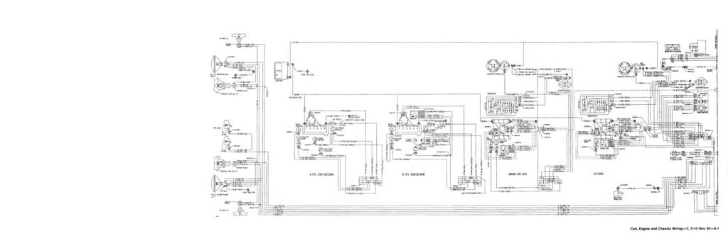
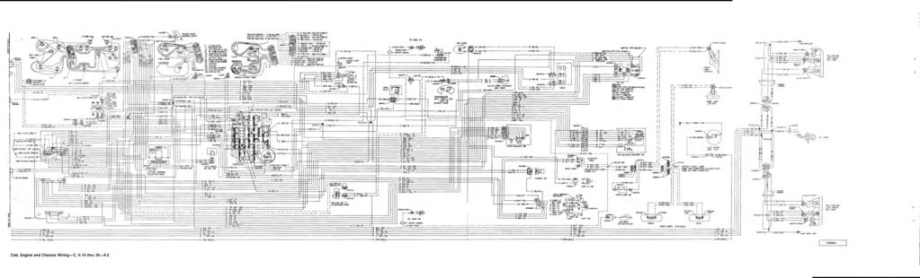
1 _f. 1 INTRODUCTION This booklet contains Wiring Diagrams for 19S0 vehicles listed in the contents below. All diagrams contained in this booklet are based on the latest product information available at the time of publication approval. The manufacturer reserves the right to make product changes at any time. Wire sizes in this booklet are metric. The following table shows metric to AWG size conversions. WIRE SIZE CONVERSION TABLE METRIC SIZE AWG SIZE (mm) I CONTENTS VEHICLE CAB, ENGINE & CHASSIS WIRING DIAGRAM C, K-I0 thru 35 A-I, 2, 3, 4, 5, 6 G-I0 thru B-1, 2, 3, 4 P-I0 thru 35.. C-l, 2 C, O-SO , 2, 3
2 ELECTRICAL CIRCUIT IDENTIFICATION Ciluit 2 Red 3 Pink Light Green Light Blue Light Blue 21 Pink Light Green Pink Light Green 37 Light Green 38 Name Feed, Battery - Un fused Feed, Ign. Sw. "On & Crank", Unfused Feed, Ign. Sw. "Accsy & On", Unfused Neutral Safety Start Sw. or Start Relay Feed Starter Solenoid Feed Primary Ignition Resistance By-Pass Instrument and Panel Lights ( No. 44 Cir.) Tail, License, Park and Side II/Iarker Lamp Feed Dimmer Sw. Feed Headlamp Feed, Hi-Beam Headlamp Feed, Lo-Beam Front Parking Lamps LH. Indicator and Front Directional Lamps R.H. Indicator and Front Directional Lamps Directional Signal Sw., Feed From Flasher Directional Signal Sw., Feed From Stop Sw. Stop and Directional Lamp or Directional Lamp Only - Rear LH. Stop and Directional Lamp or Directional Lamp Only Rear R.H. Stop Lamp (Only) Spot Light Direct Ground - Trailer Back Up Lamp Feed Feed, Voltage Regulator Field (F) (Gen/Reg.) Traffic Hazard Sw., Feed From Hazard Flasher Ground, Horn Sw. Horn Feed Fuel Gauge to k Unit Oil Pressure, Engine Map Light Feed Warning Light Brake Fog or Drive Lamp Ground, Eng. Coolant Temp. Sw. or ECM (Hot) Ground, Eng. Temp. Sw. (Cold) Ground, Eng. Metal Temp. Sw. (Hot) Flasher Feed ' Pink- - Light Green - Light Green Light Green Light Blue - Pink Name Feed, Ign. Sw. "On and Crank" - Feed, Battery - Feed, Ign. Sw. "Accsy and On" Feed, AIC Auto Relay Radio Feed I.P. and Lights Feed (Usually Light Sw. to Fuse) Marker and Clearance Lamps (Trailers) Rear Seat Speaker Feed From Single Radio or Right Stereo Auxiliary (Trailer) Tail Lp. - Headlamp Sw. "On" or Dir. Signal and Stop - Headlamp Sw. "Off" Rear L.H. Tail Lp. - Headlamp Sw. "On" or Dir. Signal and Stop - Headlamp Sw. "Off" Rear R.H. Feed, Ign. Sw. "On" Blower Resistor Feed - Low Feed, Blow Sw. "Hi" or Selector Sw. "Max Cold" Valve Release Solenoid to Control Box Control to Shield Kick Down Solenoid Feed Amplifier to Transducer LH. Cornering Lamp Feed R.H. Cornering Lamp Feed Compressor Feed Feed, Battery, Breaker Protected Ground, Resistive, Auto AIC Amb. Sensor Ground, Resistive, Auto AIC Feed Back Pot Feed, Blower Sw. "Medium 1" Blower Sw. Feed From AIC Selector Sw. Blower Motor Feed Feed, AIC Selector Sw. (Comp. Ct.) Feed, AIC Freon Press, Cut Out Sw. Ground, Resistive, Low Coolant Probe Ground Low Coolant Module Feed, Relay, Ign. Sw.
3 ,.. Ji I';;; r:}tr ELECTRICAL CIRCUIT IDENTIFICATION (Cont'd) Name 71 Ground, A/C Selector Sw. "Def" 72 Light Blue Feed, Blower Sw. "Medium 2" 73 - Feed, Blower Sw. "Medium 3" 74 Light Green Feed to Throttle Switch 75 Feed, Ign. Sw. "On and Crank" - 76 Pink Feed, Ign. Sw. 78 Light Blue Electric Choke Feed 80 Light Green Ground Key Warning Buzzer 81 Nat. Electric Remote Mirror, Right 82 Light Blue Electric Remote Mirror, Left 83 Feed, Cruise Engage Sw. "Retard" 84 Feed, Cruise Engage Sw. "Engage" 85 Ground, Cruise Indicator Regulator 86 Feed, Cruise Brake Release Sw. 88 Electric Remote Mirror, Up 89 Light Green Electric Remote Mirror, Down 90 Pink Feed, Cutout Sw., Cir. Brkr. Protected 91 Windshield Wiper Low 92 Windshield Wiper - Hi 93 Windshield Wiper Motor Feed 94 Pink Windshield Washer Sw. to Washer 95 Ground, Pulse Wiper Sw. 96 Feed, Pulse Wiper Rheostat Sw Windshield Washer Low Fluid 101 Resistor Output to Blower Relay 102 SL Alternator - Regulator Sensing 105 Ammeter - Generator 106 Ammeter - Battery 107 Over Speed Warning Light 111 Ground, Anti Ski Low Air Sw. 112 Telltale Temperature Gauge (Hot) 115 Light Blue Speaker Return, RT rr Stereo 116 Speaker Return, LF rr Stereo 117 Speaker Return, RT Frt. Stereo 118 Sp.k.RMur~LFhLShreo 119 Generator (Alternator) to Regulator 120 Electric Fuel Pump Feed 121 Tachometer to Coil 125 Door Jamb Switch 126 Seat Back Lock Feed Generator (Alternator) Ext. Resist. 2 Ohms/Foot Pink Pink Pink. - - Light Green - Light Green Name Generator (Alternator) Ext. Resist. 1 Ohm/Foot Ground, Fuel Economy Sw., Amber Telltale Ground, Fuel Economy Sw., Grn. Telltale Ground, Resistive, Temp. Gauge Sensor Feed, Ign. Sw. "On and Crank" - Feed, Battery Feed, Ign. Sw., "Accsy and On" Rr Compartment Lid Lock Release Feed Radio Sw. "On" Feed to Pwr Ant Sw. Feed, Pwr Ant Up, Relay Ground, Trunk Release Tell Tale Ground - Direct Ground Direct Ground - Direct Ground - Direct Ground - Direct Ground Direct Ground - Sw. Body Interior Lamps - such as Dome, Courtesy, Map, Warning, etc. Ground - Sw. Body Interior Lamps - such as Dome, Courtesy, Map, Warning etc. Ground - Sw. Body Interior Lamps - such as Dome, Courtesy, Map, Warning etc. Ground, Key Warning Buzzer Power Antenna Down Power Antenna Up Power Top Up Power Top Down Window Control LF Up Window Control LF Down Window Contro I R F Up Window Control R F Down Window Control LR Up Window Control LR Down Window Control R R Up Window Control R R Down Vent Control LF Close Vent Control LF Open Vent Control RF Close
4 ELECTRICAL CIRCUIT IDENTIFICATION (Cont'd) Name Vent Control R F Open Power Seat Fore Power Seat Aft or Recline Power Seat 6-Way Fore and Aft Power Seat 6-Way Solenoid - Rear - Up and Down Light Green Power Seat 6-Way Solenoid Front - Up and Down 181 Light Blue Power - Solenoid - Fore and Aft 182 Power Seat - 6-Way Aft and Down 183 Light Blue Tailgate or Center Partition Window Up Tailgate or Center Partition Window Down Light Blue Vent Control LR Open Vent Control LR Close Vent Control RR Open Vent Control R R Close Power Seat - 4-Way - Fore and Down 190 Power Seat 4-Way - Aft and Up 191 Light Green Power Seat - 4-Way Solenoid Up and Down 192 Defogger - Hi or Single Speed Defogger - Low Speed Ohms per foot 194 Electric Door Lock - Unlock 195 Light Blue Electric Door Lock - Lock 198 Light Green Ground, Resistive, AIC In-Car Sensor 199 Rear Seat Speaker - Feed from Radio Left Stereo 200 Light Green Front Speaker - Feed From Radio Single or Right Stereo 201 Front Speaker - Feed from Radio Left Stereo 202 Ground, Compressor over Heat Sw. 203 Light Blue Rear AIC Potentiometer Feed 204 Thermal Limiter Feed Seat Belt Seat Sensor to Belt Retractor (Grd) 206 Neutral Start Sw. to Buzzer and Lamp 207 Seat Sensor to Neutral Start Sw. (Lamp and Buzzer Grd) 208 Sw. Ground (TCS) 209 Park Brake Warn ing Lamp 210 Power Seat - 6-Way - Fore and Down - "A" Body 211 Power Seat - 6-Way - Aft and Up - "A" Body Stripe LH Seat Sensor 213 Center Seat Sensor RH Seat Sensor LH Sw Light Green- Light Blue 224 Light Green Pink 230 Pink Pink Name Center Buckle Sw. (Feed) RH Sw. Interlock Relay - Ground (Provided by Electronics) Starter Interlock Starter Feed Starter Interlock Buz and Lp Feed Passenger Initiator Feed, Low Level, I R Passenger Initiator Return, Low Level,IR Sensor Detector Hi Return, Low Level, IR Sensor Detector Lo Feed, Lo Feed. Low Level, I R Warning Lamp Ground I R Warning Lamp Sensor Recorder to Sensor Power Feed Warning Lamp Feed Sensor Detector Hi Feed, Lo LevellR Recorder Power Feed Driver Initiator Feed, IR Driver Initiator Return. IR Hi Level Actuation Passenger (Inactive) IR Feed, Ign. Sw., Unfused Sensor Detector Hi Feed - Hi Level IR Sensor Detector Hi Return - Hi Level IR Feed, Belt Warn Timer Con trolled (Timed 39 Ct.) Seat Belt Warn System-Buzzer Ground to Belt Assy Sw. Feed, Ign. Sw. "On & Crank" - Feed, Battery - Sensor Detector Lo Feed, H,i Level,lR Feed. Throttle Control Spark Valve Feed, Drive Selector Sw. Feed, L T FlO Solenoid Relay Feed. RT F ID Solenoid Relay Feed, ADL Lock Relay Coil Feed, to AIC Shut-Off Relay
5 ELECTRICAL CIRCUIT IDENTIFICATION (Cont'd) Name 248 Feed, to AIC Compressor Ham Relay 249 Feed. From AIC Ham '250 Feed, Ign. Sw. on. 251 Passenger Initiator Feed 252 Ground. ADL Module Unlock Output 253 Dark Ground. ADL Module Lock Output 254 Light Green Ground. ADL LT Unlock Relay Coil 255 Ground, ADL RT Unlock Relay Coil 256 Ground. Module, Lamp Out Indicator 257 Ground, AIC Press, Sw. 258 Passenger Initiator Return Hi Level. IR 259 IR Crank Start Signal- 6 Cir. 260 Theft Deterrent Hood Sw. 261 Theft Deterrent Alarm Arm 262 Light Green Theft Deterrent Key Door Unlock and Alarm Disarm 263 Light Blue Theft Deterrent Alarm 264 Theft Deterrent Arm Indication Theft Deterrent Alarm Output 266 Pink Theft Deterrent Alarm Arm Abort 267 Pwr Seat Fore and Up Recliner 268 Pwr Seat Aft and Down Recliner 269 Light Green Pwr Seat Sol Up and Down Recliner Feed, Amplifier to Potentiometer 271 Ground, Potentiometer 272 Light Green Feed, Poteniometer Rheostat 273 Feed. Hdlp Sw. to Amplifier, Hdlp Sw. 274 Feed. Hdlp Sw. to Amplifier 275 Light Green Feed, Neut Saf Start Sw. "Park" 276 Light Green Recl. Mtr. Feed, Power St. Fwd. 277 L~ght Blue Recl. Mtr. Feed, Power St. Recliner 278 Amplifier to Photocell 279 Headlamp Sw. to Photocell 280 Pink Feed, P.M. Motor Up Cycle (Deck Lid Pull Down) 281 Ground, Relay Coil Down Cycle (Deck Lid Pull Down) 282 Power Seat, Rear Vert Up Motor I'lumber Name 283 Light Blue Power Seat, Rear Vert Down - Motor 284 Light Green Power Seat, Aft Motor 285 Power Seat, Fore Motor 286 Power Seat, Front Vert Up Motor 287 Power Seat, Front Vert Down Motor Power Seat, Rear Vert Up Relay 289 Light Blue- Power Seat, Rear Vert Down Relay 290 Light Green- Power Seat, Aft Relay 291 Ground, Heated Glass Timer, On Off Sw. 292 Light Blue Feed, Heated Glass Timer. On Off SW.ll Feed. Heated Glass Timer 294 Door Lock Motor Unlock 295 Door Lock Motor Lock 296 Power Seat, Fore Relay 297 Power Seat, Front Vert Up Relay 298 Power Seat, Front Vert Down Relay 300 Feed, Ign. Sw., "On" - Un fused Snipe Relay Activated Left Directional Lamp Relay Activated Right Directional Lamp 339 Pink- Feed, Ign. Sw. On and Crank 340 Feed, Battery 350 Pink Feed, Ign. Sw. "On" Feed, Inverter to Opera Lamp 352 Opera Lamp to Inverter Return 370 Pink Feed, Avl 383 Light Blue Convert Clutch Release Sw. to Vac. Sw. 384 Light Green Vac. Sw. to Transmission Sw. Sol 385 Hi Vac Sw. to Transmission Sw. Sol 390 Feed to Side Marker and License Lamp Export Only 394 Light Green Ground, L T FlO Remote Handle Sw. 395 Light Blue Ground, RT FlO Remote Handle Sw. 402 Light Green Feed, Electronic Cruise Control Valve 403 Feed, Electronic Cruise Shut-Off Valve 404 Light Green EST Pickup Coil to HEI Module, HiQh
6 ELECTRICAL CIRCUIT IDENTIFICATION (Cant'd). Name 405 EST Pickup Coil to HEI Module, Low 406 -Green ESC Module to HEI Module, Signal Lead 407 Emergency Signal Lead, ECM to HEI Module ECM to ESC Bypass 410 ECM to Coolant Temp Sensor 411 Light Blue ECM to Fuel Metering Sol Sensor Sig Sensor Low 414 Pink 02 Sensor Heater High 415 Light Green ECM to Enrichment Sw. 416 ECM 5V Reference Voltage 417 ECM to Throttle Position Sensor Signal 418 ECM to Adaptive Sw ECM to Check Eng Lp 420 ECM to Break Sw ECM to Cold Start Program Modifier ECM to TCC Solenoid 423 EST Signal EST Bypass 425 Light Blue ECM to ISC-Motor Extend 426 ECM to ISC-Motor Retract 427 Pink ECM to ISC-Sw ECM to Canister Purge 429 -Pink ECM to Air Control Solenoid ECM Ref Pulse High 431 Light Green- 8V Ref Voltage ECM to Map Sig ECM to Baro Sig ECM to Neutral Park Sw 436 ECM to Air Switch Solenoid 437 ECM to Vehicle Speed Sensor 438 Red- ECM to High Gear Switch 439 Pink- Feed Ign. Sw. "On & Crank" 440 Feed, Battery CLCC ECM Power Grd Diagnostic Enable 452 Low Level Ground 453 -Red EST Ref Pulse Low Critical Ground Feed, Battery Breaker Protected 461 IMC to ECC, Serial Data for MPG or Diagnostics 462 Pink Ground, I MC, Set Ti ming IMC to Trip Computer Signal, Fuel Flow Data (Injector on Time) MPG Reset Signal.' Light Blue Light Green - Pink- -Light Blue Pink- -Pink Light Green- Red Green - - Light Blue - Light Blue - Green- Name Feed, Electric Fuel. IMC to Trip Computer, RPM Data Low Side of Injector "A" IMC Low Side of Injector "B" IMC Map Return, Low Level Ground Coolant Temp and Manifold Temp Return, Low Level Grd Baro Reference Voltage, 5V Manifold Air Temp Sig Baro Return, Low Level Ground Throttle Position Sensor Excitation, 5V Map Reference Voltage, 5V Throttle Position Sensor Return, Low Level Grd MPG Request Signal Fuel Economy Indicator (Grn), IMC Fuel Economy Indicator (Amber), IMC Feed, IMC Battery, Feed, for Injector "A" Feed, for Injector "B" ESC Reference Pulse High ESC Reference Pulse Low ESC Signal ESC Distributor Grd ESC Denotation Sensor Input Module - PTC, Ground Plane Sensor, Secondary PTC Sensor, Primary PTC Glow Plug, Feed or Sensor Feed, Voltage Regulator Control (Diode Isolated) Feed, Glow Plug Relay Return, Glow Plug Relay Wait Lamp Switched Grd for "Water in- k" Indicator Glow Plug, Feed or Sense, Passenger Side Power Seat - 6-Way - Fore and Down Relay to Motor Power Seat - 6-Way - Aft and Up, Relay to Motor Feed, Lt Side Trailer and Direction Feed, Rt Side Trailer and Direction Wdo Control Rf Up - Passenger Sw. Wdo Control Rf Down - Passenger Sw Wdo Control Lr Up - Lr Sw.
7 "V<'C:--?,:_? :;~ZS" "!A!!f. ~... If' " ELECTRICAL CIRCUIT IDENTIFICATION (Cont'd) Circu it Name 669 Wdo Control Lr Down - Lr Sw. 670 Wdo Control R R Up - R R Sw. 671 Wdo Control R R Down - R R Sw. 756 ~ Feed, Vac Sol (For Electronic Distributor) 801 Feed, EFI Battery, Fusible Link Protected 804 Feed, EFI, Ign. Sw. "Crank", Fusible Link Protected 807 Feed, EFI Battery, 808 Feed, EFI Module Fast Idle Valve Output and Feed, Distributor Electronics 811 Feed, EFI Module Group Two Injector Output Fusible Link Protected 812 Pink Feed, EFI Module Group One Injector Output Fusible Link Protected 813 Feed, EFI Distributor Trigger and 815, 814 Feed, EFI Distributor Trigger and 815, Name 815 Feed, EFt Module Distributor Trigger Output, 816 Pink Accelerator Enrichment Input #2 817 Accelerator Enrichment Input #1 818 Light Green Accelerator Enrichment Sw. Supply Voltage Classed Throttle Sw_ 820 Wide Open Throttle Switch 821 Ground, EFI Module Coolant Temp. Sensor Output 822 Ground Resistive, Coolant Temp. Sensor Contl'olled 823 Ground, EFI Module Air Temp_ Sensor Output 824 Ground, Resistive Air Temp. Sensor 827 Feed, EF I Module Elec Fuel Pump Output 828 Feed, EFI, Ign. Sw. "On & Crank" 831 Feed, EFI Module EGR Solenoid Output, I
8
9
10
11
12
13
Position of Parts in Engine Compartment
 [1UZ FE] Position of Parts in Engine Compartment A 1 A/C Ambient Temp. Sensor E 4 Engine Coolant Temp. Sensor (Water Temp. Sensor A 2 A/C Dual Pressure SW and A/C High Pressure SW (for Cooling Fan)) A
POWER SOURCE (Current Flow Chart)
") The chart below shows the route by which current flows from the battery to each electrical source (Fusible Link, Circuit Breaker, Fuse, etc.) and other parts. The next page and following pages show the
The chart below shows the route by which current flows from the battery to each electrical source (Fusible Link, Circuit Breaker, Fuse, etc.) and other parts. The next page and following pages show the
Position of Parts in Engine Compartment
 ELECTRICAL WIRING ROUTING [5S FE] Position of Parts in Engine Compartment A 1 A/C Ambient Temp. Sensor D 1 Distributor A 2 A/C Condenser Fan Motor A 3 A/C Idle Up VSV E 1 ECT Solenoid A 4 A/C Magnet Clutch
G ELECTRICAL WIRING ROUTING
 2 6 G ELECTRICAL WIRING ROUTING [2JZ-GTE] Position of Parts in Engine Compartment A 1 A/C Ambient Temp Sensor A 2 A/C Condensor Fan Motor A 3 A/C Triple Pressure SW (A/C Dual and Single Pressure SW) A
Position of Parts in Engine Compartment
 ELECTRICAL WIRING ROUTING [5S FE] Position of Parts in Engine Compartment A 1 A/C Condenser Fan Motor E 4 Engine Coolant Temp. Sensor (EFI Water Temp. A 2 A/C Magnetic Clutch and Lock Sensor Sensor) A
1994 Cadillac Seville STS
 Fig. 2: High-Current Fuse Panel ID (1994-95 Seville) L/H Maxi-Fuse & Circuit Breaker Identification 1-50 Amp STRG 1-2 Retained Accessory Power (Radio/Wipers), Starter, Trunk Comp Fuses 8 & 9 2-60 Amp BODY
Position of Parts in Engine Compartment
 ELECTRICAL WIRING ROUTING [3S GTE] Position of Parts in Engine Compartment A 1 A/C Ambient Temp. Sensor D 1 Date Link Connector 1 (Check Connector) A 2 A/C Condenser Fan Motor D 2 Distributor A 4 A/C Magnetic
L PART NUMBER OF CONNECTORS
 L PART NUMBER OF CONNECTORS Code Part Name Part Number Code Part Name Part Number A 1 A/C Ambient Temp. Sensor 90980-11070 B15 Blower Motor Controller (Rear) 90980-11136 A 2 A/C Magnetic Clutch 90980-11271
G ELECTRICAL WIRING ROUTING [1MZ-FE] Position of Parts in Engine Compartment
![G ELECTRICAL WIRING ROUTING [1MZ-FE] Position of Parts in Engine Compartment](/thumbs/87/97394184.jpg "G ELECTRICAL WIRING ROUTING [1MZ-FE] Position of Parts in Engine Compartment") G ELECTRICAL WIRING ROUTING [1MZ-FE] Position of Parts in Engine Compartment A 1 A/C Ambient Temp. Sensor A 2 A/C Condenser Fan Motor A 3 A/C Magnetic Clutch and Lock Sensor A 4 A/C Triple Pressure SW
G ELECTRICAL WIRING ROUTING [1MZ-FE] Position of Parts in Engine Compartment A 1 A/C Ambient Temp. Sensor A 2 A/C Condenser Fan Motor A 3 A/C Magnetic Clutch and Lock Sensor A 4 A/C Triple Pressure SW
G ELECTRICAL WIRING ROUTING
 2 6 G ELECTRICAL WIRING ROUTING Position of Parts in Engine Compartment A1 A/C Front Magnetic Valve A3 A/C Magnetic Clutch A6 A/T Flud Temp. Sensor A7 ABS Actuator A8 ABS Actuator A10 ABS Speed Sensor
POWER SOURCE (Current Flow Chart)
") POWER SOURCE (Current Flow Chart) The chart below shows the route by which current flows from the battery to each electrical source (Fusible Link, Circuit Breaker, Fuse, etc.) and other parts. The next
POWER SOURCE (Current Flow Chart) The chart below shows the route by which current flows from the battery to each electrical source (Fusible Link, Circuit Breaker, Fuse, etc.) and other parts. The next
G ELECTRICAL WIRING ROUTING
 G ELECTRICAL WIRING ROUTING Position of Parts in Engine Compartment A 1 A/C Condenser Fan Motor A 2 A/C Magnetic Clutch and Lock Sensor A 3 A/C Triple Pressure SW (A/C Dual and Signal Pressure SW) A 4
2000 Volkswagen Jetta GL
 Fig. 8: Locating Battery Fuse Panel Fuses Courtesy of VOLKSWAGEN UNITED STATES, INC. FUSE IDENTIFICATION (BATTERY FUSE PANEL) Fuse No. Amp Circuits Protected Rating 162 Engine Codes 50 Secondary Air Injector
IDENTIFICATION IDENTIFICATION > ENGINE COMPARTMENT FUSE/RELAY CENTER Chevrolet Colorado 3.5L Eng. Vehicle Reference: FUSES & CIRCUIT BREAKERS
 1 of 6 2/1/2015 5:42 PM Vehicle Reference: FUSES & CIRCUIT BREAKERS IDENTIFICATION 2005 Chevrolet Colorado 3.5L Eng CAUTION: When battery is disconnected, vehicle computer and memory systems may lose memory
G ELECTRICAL WIRING ROUTING
 G ELECTRICAL WIRING ROUTING Position of Parts in Engine Compartment A 1 A/C Ambient Temp. Sensor A 2 A/C Condenser Fan Motor A 3 A/C Magnetic Clutch and Lock Sensor A 4 A/C Triple Pressure SW (A/C Dual
SECTION 9A BODY WIRING SYSTEM
 SECTION 9A BODY WIRING SYSTEM Caution: Disconnect the negative battery cable before removing or installing any electrical unit or when a tool or equipment could easily come in contact with exposed electrical
1991 TOYOTA Electrical Components MR2. evaporator. compartment. ARTICLE BEGINNING BUZZERS, RELAYS & TIMERS
 ELECTRICAL COMPONENT LOCATOR Article Text ARTICLE BEGINNING 1991 TOYOTA Electrical Components MR2 BUZZERS, RELAYS & TIMERS A/C Compressor Clutch Relay Under right side of dash, on evaporator. Circuit Opening
G ELECTRICAL WIRING ROUTING
 G ELECTRICAL WIRING ROUTING Position of Parts in Engine Compartment A 1 A/C Condenser Fan Motor A 2 A/C Magnetic Clutch and Lock Sensor A 3 A/C Triple Pressure SW (A/C Dual and Single Pressure SW) A 4
Underhood fuse block is located at the left side of the engine compartment to the rear of the battery. See Fig. 7.
 Page 1 of 5 UNDERHOOD FUSE BLOCK NOTE: Underhood fuse block is located at the left side of the engine compartment to the rear of the battery. See Fig. 7. Fig. 7: Locating Underhood Fuse Block Courtesy
G ELECTRICAL WIRING ROUTING [5VZ FE] TOYOTA TACOMA (EWD517U) Position of Parts in Engine Compartment
![G ELECTRICAL WIRING ROUTING [5VZ FE] TOYOTA TACOMA (EWD517U) Position of Parts in Engine Compartment](/thumbs/82/86578697.jpg "G ELECTRICAL WIRING ROUTING [5VZ FE] TOYOTA TACOMA (EWD517U) Position of Parts in Engine Compartment") G ELECTRICAL WIRING ROUTING [5VZ FE] Position of Parts in Engine Compartment A 5 A/C Magnetic Clutch A 7 A/T Oil Temp. Sensor A22 ABS Actuator with ECU A23 Air Fuel Ratio Sensor (Bank 1 Sensor 1) A24 ADD
G ELECTRICAL WIRING ROUTING [5VZ FE] Position of Parts in Engine Compartment A 5 A/C Magnetic Clutch A 7 A/T Oil Temp. Sensor A22 ABS Actuator with ECU A23 Air Fuel Ratio Sensor (Bank 1 Sensor 1) A24 ADD
ELECTRICAL COMPONENT LOCATOR
 ELECTRICAL COMPONENT LOCATOR 1988 Toyota Celica 1988 TOYOTA Celica Electrical Components ---------------------------------------------------------------------- BUZZERS, RELAYS & TIMERS ----------------------------------------------------------------------
BUZZERS, RELAYS & TIMERS
 BUZZERS, RELAYS & TIMERS 1997 MAZDA MX-5 Miata BUZZERS, RELAYS & TIMERS Location A/C Relay In right front of engine compartment, near radiator. See Fig. 1. Condenser Fan Relay In right front of engine
2005 Buick Rendezvous 3.6L Eng VIN 7 Ultra Service Manual: FUSES & CIRCUIT BREAKERS Print Date: 9/16/2018
 Page 1 of 6 2005 Buick Rendezvous 3.6L Eng VIN 7 Ultra Service Manual: FUSES & CIRCUIT BREAKERS Print Date: IDENTIFICATION CAUTION: When battery is disconnected, vehicle computer and memory systems may
G ELECTRICAL WIRING ROUTING [2ZZ GE] Position of Parts in Engine Compartment
![G ELECTRICAL WIRING ROUTING [2ZZ GE] Position of Parts in Engine Compartment](/thumbs/82/84806793.jpg "G ELECTRICAL WIRING ROUTING [2ZZ GE] Position of Parts in Engine Compartment") G ELECTRICAL WIRING ROUTING [2ZZ GE] Position of Parts in Engine Compartment A 1 A/C Magnetic Clutch A 2 ABS Speed Sensor Front LH A 3 ABS Speed Sensor Front RH A 4 Airbag Sensor Front LH A 5 Airbag Sensor
G ELECTRICAL WIRING ROUTING [2ZZ GE] Position of Parts in Engine Compartment A 1 A/C Magnetic Clutch A 2 ABS Speed Sensor Front LH A 3 ABS Speed Sensor Front RH A 4 Airbag Sensor Front LH A 5 Airbag Sensor
ELECTRICAL CENTER IDENTIFICATION VIEWS > BODY CONTROL MODULE (BCM) LABEL
 LABEL") 2008 Chevrolet Cobalt 2.2L Eng LS WIRING SYSTEMS AND POWER MANAGEMENT - COMPONENT VIEWS & COMPONENT CONNECTOR END VIEWS ELECTRICAL CENTER IDENTIFICATION VIEWS > BODY CONTROL MODULE (BCM) LABEL Fig 1: View
2008 Chevrolet Cobalt 2.2L Eng LS WIRING SYSTEMS AND POWER MANAGEMENT - COMPONENT VIEWS & COMPONENT CONNECTOR END VIEWS ELECTRICAL CENTER IDENTIFICATION VIEWS > BODY CONTROL MODULE (BCM) LABEL Fig 1: View
Buckle SW Rear RH C 1 Camshaft Position Sensor Camshaft Timing Oil Control Valve RH. Crankshaft Position Sensor
 A 1 A/C Ambient Temp. Sensor 90980 11070 A 2 A/C Magnetic Clutch and ock Sensor 90980 11016 A 3 A/C Pressure Sensor 90980 10845 A 4 A/C Solenoid 90980 10901 A 5 ABS & TRAC & VSC Actuator 90980 11451 A
5/16/2017 ALLDATA Repair - Vehicle Information Volvo V L5-2.4L VIN 61 B5244S
 1/1 Battery 2/16 Relay, Intermittent Rear Window Wiping On/Off 2/17 Horn Relay 2/22 AC Relay 2/23 Fuel Pump Relay 2/29 Relay, Extended D1 Feed 2/30 X Feed Overload Relay 2/31 15-Feed Overload Relay 2/32
CONNECTOR/GROUND/SPLICE LOCATION
 AN 8W-91 CONNECTOR/GROUND/SPLICE LOCATION 8W-91-1 8W-91 CONNECTOR/GROUND/SPLICE LOCATION TABLE OF CONTENTS page CONNECTOR/GROUND/SPLICE LOCATION DESCRIPTION...1 CONNECTOR/GROUND/SPLICE LOCATION DESCRIPTION
CONFIGURATION DIAGRAMS
 80-1 GROUP 80 CONFIGURATION DIAGRAMS CONTENTS CONFIGURATION DIAGRAMS......................... 80A SPLICE LOCATIONS................................. 80B 80A-2 GROUP 80A CONFIGURATION DIAGRAMS CONTENTS OVERALL
3/22 Switch for rear power window lifts 3/23 Switch for power door mirror, driver's side 3/24 Switch for power door mirror, passenger's side 3/25
 List of Components 1/1 Battery 2/2 Relay, front foglights USA/CDN 2/3 Regulator DIM-DIP 2/4 Intermittent relay, windshield wipers 2/5 Relay, seat belt reminder/ignition key warning 2/6 Bypass relay 151
UNIVERSAL WIRING HARNESS Installation Manual
 UNIVERSAL WIRING HARNESS Installation Manual Terminals are provided for most connections on your wiring kit. Following the gauge manufacturer s instructions, use the terminals supplied with your gauge
FUSE DETAILS. Fuse Details
 2003 Jaguar S-Type (X200) V8-4.2L Vehicle > Power and Ground Distribution > Fuse > Application and ID > Components FUSE DETAILS Fuse Details https://my.alldata.com/repair/#/repair/article/40444/component/1169/itype/389/nonstandard/1247914
INSTRUCTIONS. 20 Circuit Wiring Kit Instructions October 2009, Speedway Motors, Inc.
 1 MAIN FUSE PANEL The main fuse panel harness s designed to be mounted under the dash a the firewall in an area close to the steering column. The enclosed representation of the main dash harness shows
IDENTIFICATION COMPONENT LOCATION MENU
 WIRING DIAGRAMS 1993 Mitsubishi Diamante 1993 WIRING DIAGRAMS Mitsubishi Wiring Diagrams Mitsubishi; Diamante IDENTIFICATION COMPONENT LOCATION MENU COMPONENT LOCATIONS TABLE Component Figure No. (Location)
jegs.com
 Contents Wiring Harness w/ Fuse Panel Installation Instructions Turn Signal Plug w/ Terminals 2 Headlight Plugs 3/4 Grommet 10 ¼ Terminals 4 Ring Terminals 10 Wire Ties Fusible Link 2 Screws & Nuts 2 Plastic
CONFIGURATION DIAGRAMS
 GROUP 80 CONFIGURATION DIAGRAMS CONTENTS OVERALL CONFIGURATION DIAGRAM...................... 80-2......... 80-3 .. 80-3 .. 80-5 ...... 80-7 INSTRUMENT PANEL............ 80-9 FLOOR
GENERAL INFORMATION PROCEDURE FOR HANDLING CHASSIS/DEALER CLAIMS GOVERNMENT REGULATIONS PAGE. General. Filing a Claim. Disposition of Damaged Parts
 GENERAL INFORMATION 1 PROCEDURE FOR HANDLING CHASSIS/DEALER CLAIMS General All chassis tendered for delivery by the Transportation Company are to be accepted by the Body Company. If a chassis has been
Powertrain Management: Electrical Diagrams Fuel Injection System
 1995 Volvo 940 L4-2.3L SOHC VIN 88 B230F Copyright 2009, ALLDATA 9.70 Page 1 Powertrain Management: Electrical Diagrams Fuel Injection System Wiring Diagram 1995 Volvo 940 L4-2.3L SOHC VIN 88 B230F Copyright
 Page of 0 Chevrolet Aveo.L Eng LS Service Manual: WIRING DIAGRAMS Print Date: HEADLIGHTS Fig : Headlights Circuit LOW HIGH FRT FOG EF FRT FOG HOT W/ IGN ALL ENERGIZED TIMES DASH, IN DOOR OPENING) LO LH
BUZZERS, RELAYS & TIMERS
 ELECTRICAL COMPONENT LOCATOR 1994 ELECTRICAL COMPONENT LOCATION Mazda Electrical s BUZZERS, RELAYS & TIMERS BUZZERS, RELAYS & TIMERS LOCATION ABS s Motor Relay On top of ABS pump, on right rear corner
Fuses. Fuses FUSE BOX LOCATIONS
 FUSE BOX LOCATIONS 206 When a fuse box lid is removed, take care to protect the box from moisture, and refit the lid at the earliest opportunity. Engine compartment - fuse box access: 1. Remove the two
Mustang Classic Update Series Kit
 accessory rear body 19 9 11 instrument cluster and map 10A, 0 4 3 7 40G 18 30 17A 24 1A 14A 9C 8A instrument cluster 4E 31 3 121 11 401 10A 3 400 30 washer and wiper switch 93A, 93 glovebox, map light,
COOLING FAN DEFOGGERS HORN POWER ANTENNA POWER DOOR LOCKS POWER MIRRORS POWER SEATS POWER WINDOWS RADIO 2.3L. Fig. 1: 2.3L Turbo, Cooling Fan Circuit
 COOLING FAN 2.3L Fig. 1: 2.3L Turbo, Cooling Fan Circuit DEFOGGERS Fig. 2: Defogger Circuit, W/ Electronic ATC Fig. 3: Defogger Circuit, W/O Electronic ATC HORN Fig. 4: Horn Circuit POWER ANTENNA Fig.
3/25 Switch, power sunroof 3/26 Control module, driver's seat 3/27 Control module, passenger's seat 3/28 Switch for heated driver's seat 3/29 Switch
 List of Components 1/1 Battery 2/1 Headlight relay with bulb failure sensor 2/2 Foglight relay 2/3 Regulator DIM-DIP 2/4 Intermittent wiper relay, windshield wipers 2/5 Relay, seat belt reminder/ignition
accessory connection rear body connection 40G 17A instrument cluster and map lamp ground 150A,B 15A 14A Circuit Branch 500A fog lamp switch
 accessory rear body 19 9 11 instrument cluster and map 10A, 0 4 3 7 40G 18 30 17A 24 1A 14A 9 8A instrument cluster 4E 31 3 121 11 33 401 10A 39A 400 30 washer and wiper switch 93A, 94 93 glovebox, map
GM Sample Diagram W/ Cell Reference
 1988 Chevrolet Camaro V8-350 5.7L Copyright 2013, ALLDATA 10.52SS Page 1 Vehicle: Electrical Diagrams Cell References CELL REFERENCES General Motors vehicles often use "CELL" references in their electrical
-----
 ----- - - -- - - -- - -- - - NOTE: #32 WIRE DOES NOT APPLY TO 8 AND 14 CIRCUIT HARNESSES ELECTRIC FAN #1 TO FAN SWITCH (GRAY) #21 TEMP. GAUGE (GREEN) #2 TO AC SWITCH (BLACK) JUMPER WIRE ALTERNATORS
2009 Model year NPR, NPR HD Gas Electrical Symbols. Symbol Meaning Symbol Meaning Symbol Meaning
 2009 Model year NPR, NPR HD Gas Electrical Symbols 14.1 Symbol Meaning Symbol Meaning Symbol Meaning Fuse Electronic Parts Coil (Inductor), Solenoid Magnetic Valve Fusible Link Resistor Relay Fusible Link
Instrument Cluster 30 33B 39B A B C D E F E F G H J. Connector. Circuit Branch #4. Circuit Branch #5. Circuit. Branch #6 150A. Ground.
 16 4D, 43 4B 4A & 130 100 50 39A,B,C 300 4C 4B 4C 107 3C 3D 3C 3G 3B 3F 3A 16A 3G 116 104 93 3B 3D 2E 16A 2C 2D 2B 2A 44 40 27A 40B 115 27 40A,C,E 8A,B,C Mating is plugged into accessory connector Power
This is the layout of a typical harness form a TPI Camaro.
 TPI wiring harness, typical 1986-89: This is the layout of a typical harness form a 1986-88 TPI Camaro. (A) bulkhead conn. through firewall. (B) ecm conn. (C) jct. conn for fuel injectors and cooling fan.
C915 - A147 Powertrain control module (PCM) C916 - A7 ABS control module
 C916 - A7 ABS control module") C915 - A147 Powertrain control module (PCM) C916 - A7 ABS control module C1152 - K11 Intermittent wiper relay, front C1153 - K1 Rear window heater relay C1154 - K18 ABS main relay C1155 - K25 ABS Pump
C915 - A147 Powertrain control module (PCM) C916 - A7 ABS control module C1152 - K11 Intermittent wiper relay, front C1153 - K1 Rear window heater relay C1154 - K18 ABS main relay C1155 - K25 ABS Pump
1990 WIRING DIAGRAMS Toyota. Cressida COMPONENT LOCATIONS TABLE. Figure No. (Location)
") Article Text Thursday, November 19, 1998 08:38PM ARTICLE BEGINNING 1990 WIRING DIAGRAMS Toyota Cressida COMPONENT LOCATION MENU COMPONENT LOCATIONS TABLE Component Figure No. (Location) A/C COMP CLUTCH...
Article Text Thursday, November 19, 1998 08:38PM ARTICLE BEGINNING 1990 WIRING DIAGRAMS Toyota Cressida COMPONENT LOCATION MENU COMPONENT LOCATIONS TABLE Component Figure No. (Location) A/C COMP CLUTCH...
Classic Update Series
 Classic Update Series 67-72 Ford Truck START HERE! PLEASE READ THIS EFORE STARTING INSTALLATION! This wiring kit is designed for ease of installation. Please read the guidelines below, EFORE STARTING your
3/4/15 M380 ELECTRICAL ROAD MAP
 M380 ELECTRICAL ROAD MAP A/C Pressure Switch DC Stairwell Battery 2 3 30 ABS DC Compressor Compartment 4 11 15 ABS DC Compressor Compartment 4 12 15 ABS Brake DC Compressor Compartment 4 6 5 ABS Ignition
Pigtails - Single Lead. Pigtails - Two Lead FORD UNIVERSAL
 36 Pigtails - Single Lead Pigtails - Two Lead UNIVERSAL #5747C (#5747PT) Alternator Regulator - A/C Clutch Field 1-16 ga Lead Ford 1994+ WPT852 #5610C (#5610PT) Exhaust Oxygen Sensor Pigtail 12117385 1-18
FUSES & CIRCUIT BREAKERS
 FUSES & CIRCUIT BREAKERS FUSES & CIRCUIT BREAKERS 1995 General Motors Corp. FUSES & CIRCUIT BREAKERS FUSE PANEL IDENTIFICATION (INSTRUMENT PANEL) Friday, November 27, 2009 5:05:35 5:05:39 PM Page 1 2005
Volkswagen Cabriolet DIY Guide Relay/Fuse Diagrams & Electrical System
 Volkswagen Cabriolet DIY Guide Relay/Fuse Diagrams & Electrical System Notes: 1980-1982 cars use ceramic fuses! 1980-1982 cars had a recall for the fuel pump relay. These cars should have a relay bypass
Classic Update Series
 Classic Update Series 1964-1966 Ford Mustang START HERE! PLEASE READ THIS EFORE STARTING INSTALLATION! This wiring kit is designed for ease of installation. Please read the guidelines below, EFORE STARTING
1. CAUTIONS WHEN WORKING ON ELECTRICAL UNITS
 841006 013 Fuse and relay 841006 1. CAUTIONS WHEN WORKING ON ELECTRICAL UNITS Remove the negative battery cable from the battery in advance when working on electrical units. Make sure to turn "OFF" the
Fuse and Relay Information
 11-1 Fuse and Relay Information Battery Junction Box (BJB) (14A003) PCM power diode Air suspension compressor Front fog lamp cutoff Police power Traction control indicator A/C clutch Fuel pump C1300 C1008
FUSES & CIRCUIT BREAKERS
 FUSES & CIRCUIT BREAKERS FUSES & CIRCUIT BREAKERS 1989-95 FUSES & CIRCUIT BREAKERS Ford Motor Co. INTERIOR FUSE PANEL IDENTIFICATION (1983-88 MODELS) On all models, the fuse panel is located under the
ÄÄÄÄÄÄÄÄÄÄÄÄÄÄÄÄÄÄÄÄÄÄÄÄÄÄÄÄÄÄÄÄÄÄÄÄÄÄÄÄÄÄÄÄÄÄÄÄÄÄÄÄÄÄÄÄÄÄÄÄÄÄÄÄÄÄÄÄÄÄ
 ELECTRICAL COMPONENT LOCATOR Article Text 1989 Toyota MR2 For RSe 7 HotRod Lane C'Ville VA 22901 Copyright 1997 Mitchell International Monday, May 20, 2002 12:36AM ARTICLE BEGINNING 1989 TOYOTA MR2 Electrical
 http://www.prodemand.com/print/index?content=tabs&module=true&tab=true&terms=tru... Page of //0 0 Chevrolet Malibu.L Eng LT Service Manual: WIRING DIAGRAMS Print Date: //0 EXTERIOR LIGHTS Fig : Backup
CONFIGURATION DIAGRAMS
 80A-1 GROUP 80A CONFIGURATION DIAGRAMS CONTENTS OVERALL CONFIGURATION DIAGRAM...................... 80A-2 HOW TO READ CONFIGURATION DIAGRAMS.................... 80A-3 ENGINE COMPARTMENT......... 80A-4
CIRCUIT DIAGRAMS GROUP CONTENTS HOW TO READ CIRCUIT DIAGRAMS BACKUP LIGHT TURN SIGNAL LIGHT AND HAZARD WARNING LIGHT...
 90-1 GROUP 90 CIRCUIT DIAGRAMS CONTENTS HOW TO READ CIRCUIT DIAGRAMS................................. 90-4 JUNCTION BLOCK.............. 90-10............. 90-12 CENTRALIZED JUNCTION........ 90-18 POWER
SOUL GDI REPAIR AND MAINTENANCE
 SOUL 2013-1.6 GDI REPAIR AND MAINTENANCE (First Numbers are page number within section - Numbers in parenthesis are overall document page) GENERAL INFORMATION (23 PAGES) 01-07 (01-07): Identification Number
5. Engine Control Module (ECM) I/O Signal
 I/O Signal") 5. A: ELECTRICAL SPECIFICATION B134 B135 B136 B137 17 16 15 14 13 12 11 10 9 8 27 26 25 24 23 22 21 20 19 18 34 33 32 31 30 29 28 19 18 17 16 15 14 13 12 11 10 9 8 27 26 25 24 23 22 21 20 35 34 33 32 31
5. A: ELECTRICAL SPECIFICATION B134 B135 B136 B137 17 16 15 14 13 12 11 10 9 8 27 26 25 24 23 22 21 20 19 18 34 33 32 31 30 29 28 19 18 17 16 15 14 13 12 11 10 9 8 27 26 25 24 23 22 21 20 35 34 33 32 31
CONFIGURATION DIAGRAMS
 80A-1 GROUP 80A CONFIGURATION DIAGRAMS CONTENTS OVERALL CONFIGURATION DIAGRAM...................... 80A-2 HOW TO READ CONFIGURATION DIAGRAMS.................... 80A-3 ENGINE COMPARTMENT......... 80A-4
Classic Update Series
 Classic Update Series 0-4 Ford Falcon and 0- Mercury Comet end view of terminal START HERE! PLEASE READ THIS EFORE STARTING INSTALLATION! This wiring kit is designed for ease of installation. Please read
IDENTIFICATION
 Page 1 of 6 IDENTIFICATION Page 2 of 6 Page 3 of 6 Fig. 1: Fuses & Flasher Locations FUSE BLOCKS, FLASHERS & RELAYS (CAMRY) Fuse Locations, (6), (8) Flasher Locations(2) Charge Light, Fuel Heater, Taillight
Fuses FUSE BOX LOCATIONS. Engine compartment fuse box
 Fuses FUSE BOX LOCATIONS Engine compartment fuse box 1 2 E90971 Remove the plastic cover by pressing the tabs. The fuse values and locations and the circuits protected are shown on the plastic cover. 3
Layout Diagrams. Section CONTENTS. General Layout Diagram Floor / Roof Engine Compartment Door
 1-1 Section 1 Layout Diagrams CONTENTS General Layout Diagram...1-3 Engine Compartment...1-4 Engine / Transmission...1-6 Floor / Roof...1-16 Door...1-18 Boot Compartment...1-20 Instrument Panel...1-10
1 f545633b PNDB CLDS Schematic 1 page. 2 A KIT-ELEC, POWERTRAIN PDM 1 page. 3A-3B A KIT-ELEC, POWERTRAIN PDM 2 pages
 1 f545633b PNDB CLDS Schematic 1 page 2 A06-64611 KIT-ELEC, POWERTRAIN PDM 1 page 3A-3B A06-74514 KIT-ELEC, POWERTRAIN PDM 2 pages 4A-4B G06-64121 WRG-BAT, LOW VOLTAGE DISCONNRCT 2 pages 5A-5B G06-61495
IP Fuse Block Details. LKS LTR ~ 10A ~ 10A ia 20A ld 10A Co)!XI [HVAC!J L4WD~ [HVAC~ [CRUiSE] 8 :::-:: 10A ~ 15A S 20A 0 10A4o ~ WPR WPR II> -..
![IP Fuse Block Details. LKS LTR ~ 10A ~ 10A ia 20A ld 10A Co)!XI [HVAC!J L4WD~ [HVAC~ [CRUiSE] 8 :::-:: 10A ~ 15A S 20A 0 10A4o ~ WPR WPR II> -..](/thumbs/96/126600977.jpg "IP Fuse Block Details. LKS LTR ~ 10A ~ 10A ia 20A ld 10A Co)!XI [HVAC!J L4WD~ [HVAC~ [CRUiSE] 8 :::-:: 10A ~ 15A S 20A 0 10A4o ~ WPR WPR II> -..") 8-500 Wiring Systems IP Fuse Block Details Body and Accessorl I> [AMPC] [PWR=:J [C"TSY LPJ ~IGA~ ~ LKS LTR ~ 10A
8-500 Wiring Systems IP Fuse Block Details Body and Accessorl I> [AMPC] [PWR=:J [C"TSY LPJ ~IGA~ ~ LKS LTR ~ 10A
CA 421 Installation Instructions
 CA 421 Installation Instructions PROFESSIONAL INSTALLATION STRONGLY RECOMMENDED Installation Precautions: Roll down window to avoid locking keys in vehicle during installation Avoid mounting components
WIRING DIAGRAM 1. General Description
 Page 1. General Description...1 2. Wiring Diagram...10 (1) POWER SUPPLY ROUTING...10 (2) ENGINE CONTROL SYSTEM (SOHC)...14 (3) ENGINE CONTROL SYSTEM (2.0 DOHC NA)...18 (4) ENGINE CONTROL SYSTEM (2.5 )...22
Fuse/Relay Information
 /Relay Information Under-dash /Relay Box C901 (To turn signal/hazard relay) C902 (To blower motor relay) C903 (To rear window defogger relay) C405 C404 C904 (To integrated control unit) C602 (To dashboard
1993 FD3S Touring Trim Electrical FSM Index/Supplement
 1993 FD3S Touring Trim Electrical FSM Index/Supplement Purpose: This is simply a searchable index of connectors that are found in the various 1993 FD3S wiring harnesses. Each entry shows the purpose of
Lotus Service Notes Section MP.14h
 Lotus Service Notes Section MP.14h ELECTRICS SECTION MP.14h CIRCUIT DIAGRAMS 2012MY ELISE 1ZR & 2ZR POWERTRAIN FROM VIN CH_10205 ONWARDS Description Page Contents List Circuit Diagrams 2 Circuit Diagrams
Rear Body 40D 156A 24 17A 151 3D. 8A,8B,8C under hood light. Horn Relay 91
 fuse box as viewed from the wire entry side Mating connector is plugged into Power Accessory connector 40D Rear Body 19 18 9B 30 LH Courtesy Light 40A,D 4D, 43 156B,C 16 16A 4C 3D 3C 16A 3G 4B 3G 116 4A&130
IDENTIFICATION COMPONENT LOCATION MENU
 Article Text ARTICLE BEGINNING 1992 WIRING DIAGRAMS Chrysler/Mitsubishi Wiring Diagrams Dodge; Colt Eagle; Summit Mitsubishi; Mirage IDENTIFICATION COMPONENT LOCATION MENU COMPONENT LOCATIONS TABLE Component
Pigtail - Carline Matrix Ford Vehicle Application
 Part Nr. 736 4107 001 00 TYCO 1-1670917-1 TO SENSOR PARKING AID REAR RIGHT OUTER 736 4107 002 00 Tyco 1438153-5 TO F MAF SENSOR TO SENSOR - MASS AIR FLOW AND INTAKE AIR TEMPERATURE TO MASS AIR FLOW SENSOR
Symptom Suspected Area See page Ignition switch is not set to each position. 11.Ignition switch BE 14
 BE2 BODY ELECTRICAL PROBLEM SYMPTOMS TABLE IGNITION SWITCH AND KEY UNLOCK WARNING SWITCH BE0ON18 Ignition switch is not set to each position. 11.Ignition switch BE14 Key unlock warning system does not
 http://www.prodemand.com/print/index?content=tabs&module=true&tab=true&terms=tru... Page of 8 8//07 008 Ford Expedition.L Eng VIN Service Manual: SYSTEM WIRING DIAGRAMS Print Date: 8//07 LIGHTS Fig : Backup
1991 GMC Sonoma. WIRING DIAGRAMS' '1991 WIRING DIAGRAMS General Motors Corp. WIRING DIAGRAMS WIRING DIAGRAMS General Motors Corp.
 IDENTIFICATION COMPONENT LOCATION MENU WIRING DIAGRAMS 1991 WIRING DIAGRAMS General Motors Corp. COMPONENT LOCATIONS Component Location (Figure No.) A/C COMP RELAY E 7 (2) A/C HEATER SWITCH D 4 (2) ALDL
1993 WIRING DIAGRAMS Volkswagen Wiring Diagrams. Volkswagen; Corrado
 Article Text Tuesday, December 07, 1999 11:21PM ARTICLE BEGINNING 1993 WIRING DIAGRAMS Volkswagen Wiring Diagrams Volkswagen; Corrado COMPONENT LOCATION MENU COMPONENT LOCATIONS TABLE ÄÄÄÄÄÄÄÄÄÄÄÄÄÄÄÄÄÄÄÄÄÄÄÄÄÄÄÄÄÄÄÄÄÄÄÄÄÄÄÄÄÄÄÄÄÄÄÄÄÄÄÄÄÄÄÄÄÄÄÄÄÄÄÄÄ
Automotive Parts. Charging & Starting Systems
 Automotive Parts Charging & Starting Systems Charging Systems Output voltage kept to about 2 volts higher than battery voltage Controlled by varying current into rotor field winding (voltage regulator
#T84-92: ERRATIC LIGHTS/DIGITAL DISPLAY ELEC. SYSTEM DISTURBANCES - (Aug 2, 1984)
") #T84-92: ERRATIC LIGHTS/DIGITAL DISPLAY ELEC. SYSTEM DISTURBANCES - (Aug 2, 1984) MODELS AFFECTED: 1980-1985 CADILLACS EQUIPPED WITH DEFI, DFI, CCC OR CIMARRON EFI A number of engine performance conditions,
#T84-92: ERRATIC LIGHTS/DIGITAL DISPLAY ELEC. SYSTEM DISTURBANCES - (Aug 2, 1984) MODELS AFFECTED: 1980-1985 CADILLACS EQUIPPED WITH DEFI, DFI, CCC OR CIMARRON EFI A number of engine performance conditions,
Monitor item P0011 CMP-timing over-advanced ON 1 CCM P0012 CMP-timing over-retarded ON 2 CCM
 1 of 12 Mazda 3 OBD Codes Engine No. Condition MIL DC Monitor item P0011 CMP-timing over-advanced ON 1 CCM P0012 CMP-timing over-retarded ON 2 CCM P0031 Front HO2S heater control circuit low ON 2 HO2S
ARTICLE BEGINNING COMPONENT LOCATION MENU Wiring Diagrams Audi
 Article Text ARTICLE BEGINNING 1990 Wiring Diagrams Audi 200 COMPONENT LOCATION MENU COMPONENT LOCATIONS TABLE ÄÄÄÄÄÄÄÄÄÄÄÄÄÄÄÄÄÄÄÄÄÄÄÄÄÄÄÄÄÄÄÄÄÄÄÄÄÄÄÄÄÄÄÄÄÄÄÄÄÄÄÄÄÄÄÄÄÄÄÄ Component (Figure No.) Location
2012 Isuzu Truck 16.1
 16.1 NPR, NPR HD, NQR, NRR Diesel Electrical Symbols Symbol Meaning Symbol Meaning Symbol Meaning Fuse Electronic Parts Coil (Inductor), Solenoid Magnetic Valve Fusible Link Resistor Relay Fusible Link
DIAGNOSIS SYSTEM (IPDM E/R)
") 2008 Altima DIAGNOSIS SYSTEM (IPDM E/R) Diagnosis INFOID:0000000001342651 Report a problem with this article AUTO ACTIVE TEST In auto active test mode, the IPDM E/R sends a drive signal to the following
2008 Altima DIAGNOSIS SYSTEM (IPDM E/R) Diagnosis INFOID:0000000001342651 Report a problem with this article AUTO ACTIVE TEST In auto active test mode, the IPDM E/R sends a drive signal to the following
INSTALLATION MANUAL. Remote Mobile Security System. Model: PL30
 Remote Mobile Security System INSTALLATION MANUAL Model: PL30 Copyright 1998 Magnadyne Corporation For Technical Assistance (800) 638-3600 For Fax on Demand Technical Assistance (800) 994-9977 (Must be
Symptom Suspect Area See page. 11.Ignition Switch 12.Power Source Circuit. Symptom Suspect Area See page
 BE2 PROBLEM SYMPTOMS TABLE IGNITION SWITCH: BE18204 Ignition switch is not set to each position. KEY UNLOCK WARNING SWITCH: 11.Ignition Switch 12.Power Source Circuit BE15 Key unlock warning system does
SECTION 6 4 SERVICE PROCEDURES AND SPECIFICATIONS. Electrical components
 SERVICE PROCEDURES AND SPECIFICATIONS Electrical components SECTION 6 4 Specifications........................................... 190 Checking battery condition and fluid level................... 194 Battery
2013 Isuzu Truck 16.1
 2013 Isuzu Truck 16.1 NPR HD, NQR, NRR Diesel Electrical Symbols Symbol Meaning Symbol Meaning Symbol Meaning Fuse Electronic Parts Coil (Inductor), Solenoid Magnetic Valve Fusible Link Resistor Relay
Fuse/Relay Information
 BD 10/24/91 kd 11/12 smk 11/14/91 MC 4/8/92 bd 4/14/92 92 PRELUDE /Relay Information Under-hood /Relay Box 47 46 45 44 43 42 41 40 39 31 49 48 51 50 37 36 35 34 33 32 C941 (To ABS motor relay) 38 C942
Diagnostic Trouble Codes (continued) GM Specific Codes
 GM Specific Codes") 85 GM Specific Codes P11XX Fuel and Air Metering P1106 MAP Sensor Circuit Intermittent High Voltage P1107 MAP Sensor Circuit Intermittent Low Voltage P1108 BARO to MAP Signal Comparison Too High P1111
85 GM Specific Codes P11XX Fuel and Air Metering P1106 MAP Sensor Circuit Intermittent High Voltage P1107 MAP Sensor Circuit Intermittent Low Voltage P1108 BARO to MAP Signal Comparison Too High P1111
ON-BOARD DIAGNOSTICS II SYSTEM. 5. Specified Data. Signal (V) Ignition SW ON (Engine OFF)
 Ignition SW ON (Engine OFF)") 1. ENGINE CONTROL MODULE (ECM) I/O SIGNAL OBD0092A Crankshaft Camshaft Mass air flow Throttle Signal (+) 8 0 7 +7 Sensor output waveform Signal ( ) 29 0 0 Shield 54 0 0 Signal (+) 7 0 7 +7 Sensor output
1. ENGINE CONTROL MODULE (ECM) I/O SIGNAL OBD0092A Crankshaft Camshaft Mass air flow Throttle Signal (+) 8 0 7 +7 Sensor output waveform Signal ( ) 29 0 0 Shield 54 0 0 Signal (+) 7 0 7 +7 Sensor output
5. Engine Control Module (ECM) I/O Signal
 I/O Signal") 5. Engine Control Module (ECM) I/O Signal A: ELECTRICAL SPECIFICATION B134 B135 B136 B137 17 16 15 14 13 12 11 10 9 8 27 26 25 24 23 22 21 20 19 18 34 33 32 31 30 29 28 19 18 17 16 15 14 13 12 11 10 9
5. Engine Control Module (ECM) I/O Signal A: ELECTRICAL SPECIFICATION B134 B135 B136 B137 17 16 15 14 13 12 11 10 9 8 27 26 25 24 23 22 21 20 19 18 34 33 32 31 30 29 28 19 18 17 16 15 14 13 12 11 10 9