Deicer Operating Instructions Table of Contents
|
|
|
- Jocelyn Violet Pitts
- 5 years ago
- Views:
Transcription
1 Deicer Operating Instructions Table of Contents FMC FMC FMC/Trump FMC Global Premier Trump Model: LA1000 Model: LMD-2000 Model: T2000 Model: TM1800 Model: 2100TE Model: HC29050 Model: D240 Contents

2 FMC OPERATING INSTRUCTIONS EQUIPMENT: Deicer MANUFACTURER: FMC Model: LA1000 TYPE: Gas Model: LA1000 BEFORE STARTING Complete Daily Check before using. Check placards for special instructions and restrictions. Check location of levers, switches and controls. Check general condition of entire unit. Contents
3
4
5
6
7
8
9
10
11
12
13
14

15 FMC OPERATING INSTRUCTIONS EQUIPMENT: Deicer MANUFACTURER: FMC Model: LMD-2000 TYPE: Diesel Model: LMD-2000 BEFORE STARTING Complete Daily Check before using. Check placards for special instructions and restrictions. Check location of levers, switches and controls. Check general condition of entire unit. Controls Contents
16 Figure 2 Cab Controls Contents

17
18 Figure 4 Upper Panel Basket Controls Contents
19
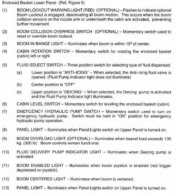
20 Figure 5 Basket Controls Lower Panel Contents
21

22 Figure 6 Contents
23

24 Figure 18 Figure 19 Contents
25
26
27
28
29

30 Figure 9 Contents
31
32
33
34
35
36

37 Figure 14 Figure 15 Contents
38
39
40 Figure 16 Contents
41
42
43
44
45
46
47


48 FMC/Trump Model: T2000 OPERATING INSTRUCTIONS EQUIPMENT: Deicer MANUFACTURER: FMC/Trump TYPE: Diesel Model: T2000 BEFORE STARTING Complete Daily Check before using. Check placards for special instructions and restrictions. Check location of levers, switches and controls. Check general condition of entire unit. Contents
49
50

51
52
53

54
55
56
57
58
59
60
61
62
63
64
65
66
67
68
69
70
71

72 FMC OPERATING INSTRUCTIONS EQUIPMENT: Deicer MANUFACTURER: FMC Model: TM1800 TYPE: Gas Model: TM1800 BEFORE STARTING Complete Daily Check before using. Check placards for special instructions and restrictions. Check location of levers, switches and controls. Check general condition of entire unit. Contents
73
74
75
76
77
78
79
80
81
82
83
84
85
86
87
88
89
90
91
92
93
94

95 Global Model: 2100TE OPERATING INSTRUCTIONS EQUIPMENT: Deicer MANUFACTURER: Global TYPE: Diesel Model: 2100TE BEFORE STARTING Complete Daily Check before using. Check placards for special instructions and restrictions. Check location of levers, switches and controls. Check general condition of entire unit. Controls Contents
96
97 Daily Operations Check Note: As with any heavily used piece of machinery, this unit will require maintenance at regular intervals to maintain optimal performance. A walk around check is required prior to the first operation of the day. Truck 1. All fluid levels should be at or above the Add mark. For specific check intervals, see the Freightliner Business Class M2 Maintenance Manual, the Detroit Diesel MBE 900 Engine Operator s Guide, and the Allison Operator s Manual. 2. Check hydraulic oil level. Proper level is 1/2 to 2/3 full as seen on the sight gauge. 3. Check auxiliary engine fluid levels. 4. Check fuel levels in truck cab: a. Check truck engine fuel on fuel gauge located in the main instrument cluster. b. Check the auxiliary engine and heater fuel level located in the cab control panel. Make sure there is adequate fuel to do the job. 5. Check the parking brake for proper operation. With the parking brake set and the unit in gear, it should not move. 6. Check tires as follows: a. Check tire pressure. Inflate to the amount shown on the decal above the tire. b. Visually check the tire side walls for physical damage (cuts, bruises, etc.). c. Visually check lug bolts and safety rims for signs of damage or looseness. 7. Visually check fluid levels on tanks. Check that the manual sight gauge on the side of the tank agrees with the gauge in the cab control panel. The deicing fluid level must remain at or above the specified minimum level. 8. Walk around the unit, checking the body parts for physical damage and looking for any obvious signs of leakage. Contents
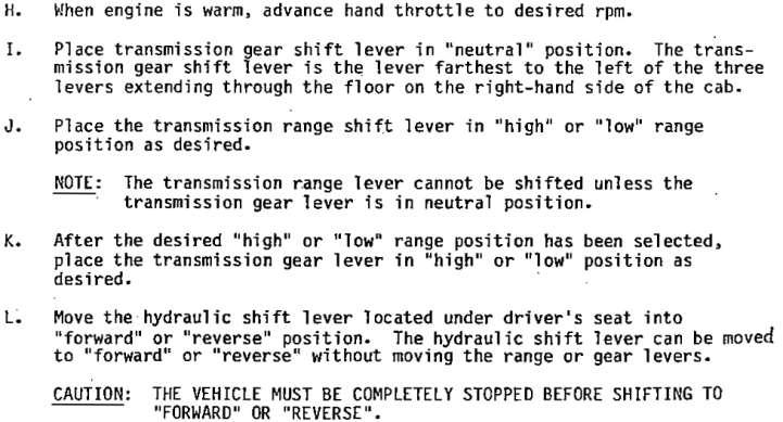
98 Starting The Truck 1. Cab Of The Truck a. Enter the cab, following safety precautions recommended in the Freightliner Business Class M2 Driver s Manual. b. Make sure the emergency/parking brake is set. c. Make sure the automatic transmission is in neutral. d. Use the ignition key switch to start the engine. e. Allow the engine to come up to operating temperature. Driving 1. Standard Drive The truck controls operate in a standard fashion according to the Freightliner Business Class M2 Driver s Manual. Note: Set the parking brake and shift into neutral, then turn the engine off when stopping the vehicle. 2. Deicing Drive When the boom is out of the rest, the truck speed is limited to a maximum of 4 mph (6 km/hr). Filling The Deicing And Anti-Icing Fluid Tanks 1. Fluid Tank Level Gauges There are two fluid tank level gauges for the each of the two fluid tanks. There is a sight gauge on each tank on the drivers side of the deicer, and a deicing and anti-icing gauge on the control panel in the truck cab. On the sight gauge for deicing fluid, 1 inch equals 33.4 US gallons (2.54 cm equals liters). On the gauge for anti-icing fluid, 1 inch equals 3.6 US gallons (2.54 cm equals 13.6 liters). Contents
99 2. Top Fill Warning Top fill should be attempted only with the necessary safety equipment and proper approval from supervisory authorities. a. Set the parking brake and turn the engine off. Warning Access steps and the top of the deicer body are exposed to overspray and spills. Clean the surfaces and observe safety precautions when climbing. b. Climb to the top of the deicer body using the access steps. Caution Remove all dirt and buildup on or near fill ports. Use only clean hoses and fittings to avoid fluid contamination. c. Unlatch the proper tank cover. d. Fill the tank with the proper fluid. e. Monitor the fluid level while filling the tank. f. Latch the cover after the filling the tank. g. Climb down using the access steps. Contents
100 3. Bottom Fill a. Ensure that tank shut-off valve is closed (refer to Figure 7). When the shut-off valve handle is in line with the ball valve housing, the valve is open. When the handle is perpendicular to the valve housing, the valve is closed. Normal operation requires that the valve be closed. Caution Remove all dirt and buildup on or near fill ports. Use only clean hoses and fittings to avoid fluid contamination. b. Remove the fill cap. c. Connect the coupling and hose. d. Open the tank valve. e. Fill tanks with the proper fluids. f. Monitor filling using driver's side sight gauges. g. When tanks are full, close the valves. h. Disconnect the coupling and hose. i. Replace cap. 4. Anti-Icing Suction Fill a. Truck or auxiliary engine must be running at an idle, with the transmission in neutral. b. Set the parking brake. c. Move the Pumps switch in the truck cab to the On position. d. Open curb side pump skid doors for access to ports, ball valves, and suction toggle switch. e. Locate the external suction fill port on the anti-icing pump. f. Remove fill cap. g. Attach a suction hose to this port on the anti-icing pump suction line. h. Place suction hose in anti-icing fluid container. i. Move the suction line ball valve handle (on inlet side of pump) to anti-icing suction fill position. j. Move pressure line ball valve handle to anti-icing suction fill position. k. Move toggle switch at anti-icing pump to the On position for suction fill. l. Move toggle switch to the Off position when fluid tank is full or anti-icing container is empty. m. Move the suction and pressure line ball valves to the normal operation positions. n. Remove the suction hose and replace the cap. Contents
101
102 5. Deicing Suction Fill a. Make sure the truck transmission is in neutral and the parking brake is set. b. Locate the deicer suction drain and fill connection on the street side of the truck and attach a siphon hose to the coupling. c. Attach the other end of the hose to the deicing fluid source container. d. Place the fill valve in the open position. e. Locate the suction fill valve on the curb side of the truck, in the fluid pump compartment. f. Place the valve in the fill operation position. g. Start the auxiliary engine from the cab control panel. Indicator lights on the proximity switches will come on to show that the valve is in the open position. h. Move the Pumps switch on the cab control panel to the On position to transfer fluid to the deicing tank. i. Move the Pumps switch to the Off position when the tank is full or the source container is empty. j. Turn the auxiliary engine off. k. Place the suction fill valve in the normal operation position. l. Remove the siphon hose from the deicing fill port and place the fill valve in the normal operating position. Contents
103 Starting The Deicing Operation 1. Pre-Operation Inspection Before operating the deicer, a visual inspection should be performed to locate any indications of obvious body and/or tire damage and to check all truck fluid levels. If any of these fluids are low, follow standard procedures for filling to proper levels. It is also important to ensure that all lights and both windshield and overhead wipers are operating properly for both day and night time operations. 2. Fuel Systems a. Truck fuel system supply tank is 50 gallons. b. Deicing unit and heater fuel are 155 gallons. Start-Up Procedures 1. Make sure automatic transmission is in neutral and emergency/parking brake is set. 2. Use the ignition switch to start the truck engine. Allow engine to warm up. 3. Allow air brake pressure to build up. 4. Start the auxiliary engine using the cab control auxiliary engine ignition switch. Refer to Figure 10. Turn the switch to the On position, wait until glow plug light goes out, then turn the switch to the Start position. Allow the engine to warm up. 5. Activate pumping system by turning pump switch to On. After a few seconds the auxiliary engine speed should increase to about 2,100 rpm. 6. Activate heating system by turning heater switch on. 7. Ensure the green heater on light stays on during the heating cycle. 8. Fluid temperature should increase to approximately 180 F (82 C) in 2-3 minutes. Contents
104
105 Shut-Down Procedures 1. Shut down heater by turning heater switch to Off. Caution The heater must be allowed to cool for a minimum of three minutes before performing Step Switch pumps to Off. 3. Ensure boom is fully stowed into the boom rest. Caution The engine must be at idle and the truck at a complete stop prior to shifting the automatic transmission into gear. 3. Shut auxiliary engine off. 4. Move shifter to drive or reverse, as required. 5. Release the parking brake. 6. Drive to storage facility. 7. Park the unit in its proper place. 8. Set the parking brake. 9. Move shifter to neutral. 10. Make sure all lights are off. 11. Turn ignition switch off. Contents
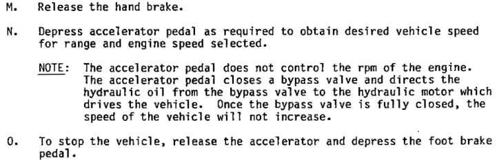
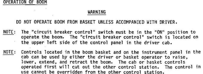
106 Aerial Device Operation Operating the boom shall be made under controlled conditions. The operator shall be properly trained in the operation of the aerial device. Operator shall wear the four-point harness in the enclosed cab or a safety harness with the lanyard attached to the designated anchor point if operating from a basket. The deicer operator shall remain at the controls when the enclosed cab is occupied. Movement of the enclosed cab/basket shall be done in a slow, controlled, and cautious manner with no sudden movements of the aerial device. The aerial device shall not be operated in winds in excess of 46 mph (74 km/hr). The aerial device may be operated while driving the deicer unit to position it in the work place. 1. Preparation Caution Always engage the deadman trigger with the joystick in its neutral/static position. If you move the joystick, then pull the trigger, the boom will not move smoothly. Releasing the trigger causes aerial device/boom movement to stop. Note: Fluid/air nozzle must be lowered prior to opening the enclosed cab entry/exit door. The nozzle stow switch is on the curb side of the enclosed cab at rear. a. Open the entry/exit door. b. Enter the enclosed cab/basket. Make sure door latch is fully latched. c. Put on the safety harness/seat belt. d. Put on the headset. e. Turn enclosed cab/basket light switch on; the auxiliary engine must be running. f. On enclosed cab machines, before moving the aerial device, check that the Boom Stow and Cab Rotation Position Indicator Signal lamps are On to ensure proper usage when deicing operation is completed and boom is ready to stow. Contents
107 2. Moving The Aerial Device Caution When raising the aerial device from or lowering it to its stowed position make sure to extend the boom so that the enclosed cab/basket clears the truck front bumper. a. Activate the joystick by pulling and holding the red deadman trigger. Refer to Figure 11. Note: Releasing the deadman trigger causes all aerial device movement to stop. Caution Always engage the deadman trigger with the joystick in its static position. If you move the joystick, then pull the trigger, the boom will still move, but the movement will be jumpy. Contents
108 b. Move joystick in the proper direction to position aerial device 1) Boom Lift Push the joystick forward to move the boom down. Pull the joystick back to move the boom up. 2) Swing Push the joystick to the left to swing the boom left, or CCW. Pull the joystick to the right to swing the boom right, or CW. 3) Cab Rotation Enclosed Cab Twist the joystick CW to rotate cab rotation CW. Twist the joystick CCW to rotate cab rotation CCW. 4) Extension Rotate the thumb switch to the left to extend the boom. Rotate the thumb switch to the right to retract the boom. 5) Fly Enclosed Cab Push toggle switch forward to move the fly out. Push toggle switch back to move the fly in. 6) Fly Basket Twist the joystick CW to move the fly out. Twist the joystick CCW to move the fly in. Contents

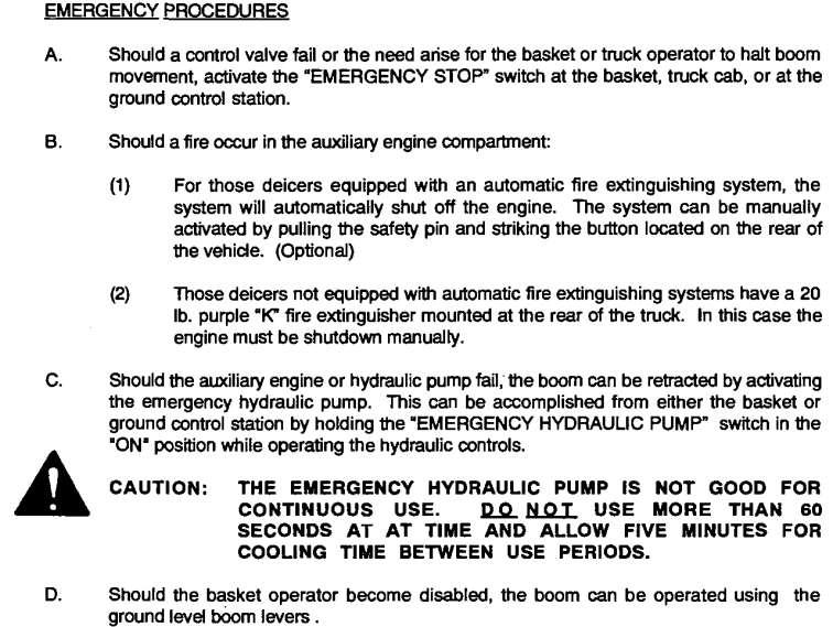
109 c. Press an emergency stop button should an emergency occur. There are three Emergency Stop buttons on the deicer: one on the enclosed cab control panel/basket control, one in the truck cab, and one on the ground level control panel. Note: Pressing an emergency stop button immediately stops all boom movement, spraying, and the auxiliary engine. To resume operations; pull the emergency stop button outward, turn off the pumps and heater switches, and place the auxiliary engine switch in the Off position. Restart the auxiliary engine. Contents

110 Three Nozzle Enclosed Cab Deicing And Anti-Icing Operation Deicing and anti-icing fluid is sprayed using the same controls, but different nozzles. The fluid flow rate of the nozzles is not adjustable. A selector switch is used to select between various anti-icing, deicing, or air plus options. This switch controls an electric actuator to provide positive fluid selection. The fluid options are: Anti-Icing Fluid anti-icing fluid only through the anti-icing nozzle Deicing Fluid deicing fluid only through the deicing nozzle Force Air Air Plus operation only Fluid Injection deicing fluid injected into the Air Plus nozzle air stream Deicing Fluid and Force Air deicing fluid and Air Plus operation Deicing Fluid and Fluid Injection deicing fluid through the deicing nozzle and injected into the Air Plus nozzle air stream Contents
111 1. Choose the type of fluid for the application by placing the rotary selector switch in the proper position. Refer to Figure Open the spray nozzle by engaging the deadman trigger. Warning Temperature of fluid flow from the nozzle can be over 185 F (85 C). 3. Press the rocker switch on top of the joystick to one side or the other to adjust the deicing spray to desired pattern. The anti-icing spray pattern is not adjustable. a. Press right side for a more solid spray pattern. b. Press left side for a mistier (wider) spray pattern or nozzle flush. 4. Monitor the pressure of the deicing or anti-icing fluid at the nozzle using the pressure gauge on the left side console in the enclosed cab. 5. Press an emergency stop button should an emergency occur. Contents
112 Completing The Deicing Operation 1. Enclosed cab with two nozzles: depress the fluid control foot pedal backwards to close the spray nozzle. Enclosed cab with three nozzles: release the nozzle control joystick deadman trigger to close the spray nozzle. Basket: push the flow control handle forward to close the spray nozzle. 2. Retract the boom fully, and then extend the fly boom at least 1? (30 cm). 3. Swing the boom until it is positioned directly over the boom rest. 4. Enclosed cab: rotate the cab until it is centered with the boom. 5. Lower the boom onto the boom rest. 6. Retract the fly boom until the enclosed cab/basket is returned to its fully stowed position. 7. Turn off enclosed cab/basket lights. 8. Enclosed cab: place nozzle horizontal in the 10 o'clock position. 9. Remove four-point/safety harness. 10. Remove headset. 11. Lift safety latch to exit enclosed cab/basket door. 12. Exit and close the door. 13. Enclosed cab: place the nozzle in the fully stowed position using the toggle switch on the exterior of the enclosed cab. Contents
113 Ground Level Aerial Device Controls Note: It is recommended that an observer near the front of the vehicle provide visual assistance when operating ground level aerial device controls. 1. Lift the protective cover of the Aerial Device Manual Control Switch. Refer to Figure Flip the switch to its On position to activate ground level boom movement controls. Note: Activating the ground level or lower controls, overrides the enclosed cab/basket controls, and all emergency stop switches. 3. Move the proper lever to position the aerial device a. Topping Move the lever down to move the boom down. Move the lever up to move the boom up. b. Extension Move the lever up to extend the boom Move the lever down to retract the boom. c. Swing d. Fly Move the lever down to swing the boom clockwise. Move the lever up to swing the boom counterclockwise. Move the lever up to move the fly up. Move the lever down to move the fly down. e. Enclosed Cab/Basket Leveling Move the lever up to tilt up. Move the lever down to tilt down. Caution Manual leveling does not automatically override auto-leveling and should only be used if autoleveling has failed. When raising the aerial device from, or lowering it to its stowed position, make sure to extend the boom so that the enclosed cab/basket clears the truck. Contents
114 4. Return Aerial Device Manual Control switch to Off position (close cover) after completing operations. Do not leave switch on when not using manual controls. Contents
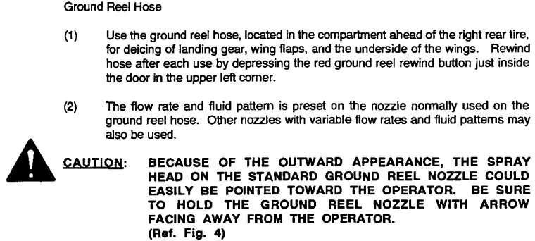
115 Ground Hose The ground hose may be used to spray deicing fluid. The ground hose nozzle spray pattern is not adjustable. Warning Temperature of fluid from the spray nozzle can be over 185 F (85 C). Operator must be aware of spray nozzle opening location. Failure to do so increases the risk of inadvertently spraying the operator. Arrow on nozzle indicates the direction of spray. 1. With heater and pumps on, open the ground reel ball valve on the left side of the hose reel. 2. Pull the nozzle and hose to the desired location. 3. Squeeze the control handle to open the spray nozzle. 4. Release the control handle to close the spray nozzle. Warning Make sure the hose is free of obstructions before pressing the rewind button. Wind the hose completely on the reel before moving the deicer. 5. Press the automatic rewind button and guide the hose onto the reel. Contents
116 Air Plus System 1. Turn the auxiliary engine on. 2. Turn the pumps switch on in the truck cab. 3. The type of controls in the enclosed cab depends on the nozzle option on the unit. a. Enclosed Cab With Three Nozzles Activate the system by placing the rotary selector switch in the proper position for the work to be performed. The Air Plus options are: Force Air Air Plus operation only Fluid Injection deicing fluid injected into the Air Plus nozzle air stream Deicing Fluid and Force Air deicing fluid and Air Plus operation Deicing Fluid and Fluid Injection deicing fluid through the deicing nozzle and injected into the Air Plus nozzle air stream Engage the deadman trigger to operate the air system compressor. Contents
117 4. Air Plus Monitoring a. Oil Pressure Low Pressure Light The oil pressure light will come on and stay on when system oil pressure is less than 5 psi (0.35 kg/cm2). 1) Switch will latch off and prevent operation. 2) To reset: Press Emergency stop, turn heater and pumps Off, restart auxiliary engine, and then turn heater and pumps On. b. Oil Temperature Over Temp Light Oil temperature gauge will indicate temperature of compressor return oil. Oil temperature light will illuminate if system oil temperature exceeds 275 F (135 C). 1) Switch will latch off and prevent operation. 2) To reset: Press Emergency stop, turn heater and pumps Off, restart auxiliary engine, and then turn heater and pumps On. c. If problems still exist, contact maintenance. Contents
118 Enclosed Cab Heater The enclosed cab is heated using a fan and radiator drawing warmth from circulated deicing fluid. The radiator and fan is mounted below the right console in the enclosed cab. A fan control knob mounted on the front of the console provides the operator with options for increasing or decreasing air circulation through the radiator. Another circulation fan is mounted on the ceiling in the top left rear corner of the enclosed cab. A toggle switch on the fan housing controls fan operation. The fan can be directed by turning the fan housing on its swivel mount. The fan is situated near the top rear sliding window of the enclosed cab to promote fresh air circulation. This window can be opened and closed from inside the enclosed cab. Note: Operation of the rear enclosed cab window may require two hands due to stiffness in the weather seal around the window. Adjust fresh air circulation and radiator heat circulation to reduce and control window fogging. Contents

119 Windshield Wipers And Washers The deicer truck cab overhead window and enclosed cab windows can be washed and wiped using installed window washers and wipers. The deicer truck cab overhead window washer and wiper control is mounted on the truck cab control panel between the passenger and driver s seat. Depressing the push button starts the wiper in a cycle of wiping and washing the window. The cycle is short to prolong the life of the system. Depressing the button and holding it will spray washer fluid on the window until the button is released. The washer fluid for the deicer truck cab overhead window is stored in a three quart (2.8 liter) container mounted near the floor, between the driver and passenger s seats. Tubes extend from the washer fluid pump to two nozzles on the top right and left corners of the exterior of the overhead window. The nozzles have been adjusted at the factory for optimal coverage of the window surface. Caution Do not use ammonia based cleaning products on the enclosed cab windows. This will cause a haze on the Lexan material that will cause permanent damage with long term use. In the enclosed cab, left, right and front washer and wiper controls are mounted overhead and to the right, on a electrical control box near the interior ceiling of the enclosed cab. The left and right window wiper controls are push buttons. Depressing a button starts a cycle of wiping and washing of a window. The control for the front wiper is a knob, which can be turned to adjust the speed of the wiper sweep. Depressing the knob sprays washer fluid on the window. Contents

120 Lights The flashing safety beacon mounted on the turret may be turned On and Off with a toggle switch on the upper right corner of the cab control panel. On some models the light comes on when the chassis engine is started. There are four flood lights on top of the cab which face forward and one flood light mounted on the nozzle that moves with the nozzle for spray operations. These lights are turned on with toggle switches in the enclosed cab on the curb side overhead console. The enclosed cab has a dome light mounted on the left rear ceiling that is operated with a push button on its housing. The street side console in the enclosed cab has a light that is turned on when the nozzle lights are on. The housing around the bulb may be turned to direct the light to the desired position. The light is placed close to the fluid pressure gauge to aid visibility during night operation. On the outside front of the basket are two halogen flood lights which face forward toward the work area. A toggle switch to turn the lights on and off is on the top of the basket control panel. There is a light inside the deicer body. The switch to turn this light on and off is on the front of the master electrical panel at the curb side rear of the body. Contents
121 Intercom System The truck cab and enclosed cabs share a communications system. The truck cab operator uses a single ear headset, while the enclosed cab/basket operator uses a dual ear headset. The master station for the truck cab is mounted above and behind the driver s seat, centered on the back wall of the cab. The smaller remote station for the enclosed cab is mounted above, behind and to the left of the operator s seat. The remote station for the basket is mounted on the boom above the basket mounting bracket. To operate the intercom system, the truck chassis ignition switch must be turned on and the On/Off push button on the master station in the truck cab must be illuminated. A black button on the headset turns the voice activated microphone on and off. Three controls and two headset receptacles on the master station allow a passenger and/or the driver to communicate with the enclosed cab operator. The center control knob on the master station controls system volume. Each station has connection cables which can be unplugged. Headsets plug into receptacles with removable weather covers. Rotating knobs on the stations control signal volume in the headset plugged into the station. Contents


122 Premier Model: HC29050 OPERATING INSTRUCTIONS EQUIPMENT: Deicer MANUFACTURER: Premier TYPE: Diesel Model: HC29050 BEFORE STARTING Complete Daily Check before using. Check placards for special instructions and restrictions. Check location of levers, switches and controls. Check general condition of entire unit. Control Panel Contents
123
124

125 Trump Model: D240 OPERATING INSTRUCTIONS EQUIPMENT: Deicer MANUFACTURER: Trump TYPE: Gas Model: D240 BEFORE STARTING Complete Daily Check before using. Check placards for special instructions and restrictions. Check location of levers, switches and controls. Check general condition of entire unit. Contents
126
127
128
129
130
131
132
133
134
135
136
137
138
139
140
141
142
143
144
145
146
147
148
149
150
151
152
SECTION 1 DESCRIPTION
 1 SECTION 1 DESCRIPTION 1. General Description This manual details design and performance features of the Regional Series Model 4542 (1200) TE Aircraft Deicer. The 4542 (1200) TE offers 1,200 US gallons
32 quarts Transmission Allison HT 740 Automatic Fluid
 BOOK: Blue Book I SECTION: E-One Engine (SGT) Page 1 of 6 E-ONE CYCLONE TABLE OF CONTENTS SPECIFICATIONS... 2 DAILY CHECKS... 2 SAFETY CHECKS... 3 START ENGINE... 3 STOP ENGINE... 3 EMERGENCY SHUTDOWN
Commander 15i Container and Pallet Loader. Property of American Airlines
 Commander 15i Container and Pallet Loader Section 2. Operation BEFORE ATTEMPTING TO OPERATE OR MAINTAIN THE VEHICLE, COMPLETELY READ AND UNDERSTAND THE OPERATION AND MAINTENANCE MANUAL, INCLUDING ALL DANGER,,
CAUTION. Start & Stop Procedures. Section 1-2. Engine Oil Level
 Section 1-2 Start & Stop Procedures Before operating this machine, the operator must have: received operator training, a familiarity with this manual, and a complete understanding of all the procedures
As a safety precaution, remove keys from the ignition while working under or around the vehicle.
 CAB AND CHASSIS As a safety precaution, remove keys from the ignition while working under or around the vehicle. 1. Approach Check the overall appearance of vehicle stance (not leaning). Check for signs
Chapter 2 Maintenance Instructions
 Chapter 2 Maintenance Instructions Chapter 2 Page 1 Chapter 2 Page 2 This Page Intentionally Left Blank Table of Contents Chapter-Section Page Section 1 General Procedures... 2-1... 5-8 1. Safety Practices...
CAUTION. Start & Stop Procedures. Section 4-2. Engine Oil Level
 Section 4-2 Start & Stop Procedures Before operating this machine, the operator must have: received operator training, a familiarity with this manual, and a complete understanding of all the procedures
Property of American Airlines
 MH Utility Vehicle Section 2 SECTION 2: OPERATION A. CONTROLS, INSTRUMENTS AND SWITCHES The tractor controls and instruments include a headlight switch, ignition switch, hour meter, ammeter (if equipped),
Property of American Airlines
 Section 2: Operation 1. GENERAL INFORMATION Safety First! is the motto at Tesco; therefore, the first part of the Operation section begins with safety features and procedures. Operation of the Tesco CL80-20
SECTION 1 2 INSTRUMENTS AND CONTROLS. Switches
 SECTION 1 2 INSTRUMENTS AND CONTROLS Switches Headlight and turn signal switch............................ 16 Fog light switch........................................... 17 Windshield wiper and washer
ESCONDIDO FIRE DEPT TRAINING MANUAL Section DRIVER OPERATOR Page 1 of Sutphen Aerial Operations Revised
 DRIVER OPERATOR Page 1 of 10 1997 Sutphen Aerial Operations Revised 12-11-17 PROCEDURES FOR ELEVATING THE PLATFORM Placing the aerial platform into service requires qualified personnel trained in the proper
Part 1 OPERATION OF INSTRUMENTS AND CONTROLS
 Part 1 OPERATION OF INSTRUMENTS AND CONTROLS Chapter 1-4 Lights, Wipers and Defogger Headlights and turn signals Emergency flashers Instrument panel light control Front fog lights Interior lights Ignition
TC Series Cooling Systems
 TC Series Cooling Systems Table of Contents Table of Contents...1 List of Figures...1 Safety...2 Introduction...2 General Specifications...2 Types of Coolant...2 Routine Maintenance...2 Surge Tank Coolant
Property of American Airlines
 Section 2. Operation 1. GENERAL FOR EMERGENCY OPERATING INSTRUCTIONS REFER TO CHAPTER 1, SECTION 3. This section contains instructions for operation of the B350. A discussion of the principles of operation
ESCONDIDO FIRE DEPT TRAINING MANUAL Section DRIVER OPERATOR Page 1 of Sutphen Aerial Operations Revised
 DRIVER OPERATOR Page 1 of 12 2014 Sutphen Aerial Operations Revised 12-11-17 PROCEDURES FOR ELEVATING THE PLATFORM Placing the aerial platform into service requires qualified personnel trained in the proper
Automated Control Electronics (ACE ) System Operation and Diagnostics
 System Operation and Diagnostics") Commercial Products Automated Control Electronics (ACE ) System Operation and Diagnostics PART NO. 98962SL This page is intentionally blank. Table of Contents Introduction... 1 Controller Operation and
Commercial Products Automated Control Electronics (ACE ) System Operation and Diagnostics PART NO. 98962SL This page is intentionally blank. Table of Contents Introduction... 1 Controller Operation and
Property of American Airlines
 - GASOLINE MANUAL NUMBER 092602 EFFECTIVITY: 09/26/02 GASOLINE POWERED Scissor Lift Vehicle -1036S thru -1037S REV 00 CORPORATION 9501 SOUTH CENTER ROAD MUNCIE, IN 47302-9443 P.O. BOX 2645 MUNCIE, IN 47307-0645
Portable Lighting Equipment Operating Instructions Table of Contents
 Portable Lighting Equipment Operating Instructions Table of Generac Magnum Ingersoll Rand TEREX AMIDA TEREX GENIE Model: MLT3060 Model: LIGHTSOURCE Model: Amida AL4000 series Model: TML4000N Generac Magnum
WILDFIRE OPERATOR TRAINING MANUAL
 WILDFIRE OPERATOR TRAINING MANUAL 1 WildFire Component Locations Turn Signal Switch Accessory Switch Panel Generator Start/Stop Switch and Hour Meter Fig. 1 Brake Pedal Gas Pedal 2 WildFire Component Locations
before serial number 2214
 before serial number 2214 Contents Page Safety Rules... 3 Pre-operational & Safety Inspection... 4 Operating Instructions... 6 Transport... 12 Maintenance & Routine Service... 12 Specifications... 14 SAFETY
GPU Equipment Operating Instructions Table of Contents
 GPU Equipment Operating Instructions Table of Briggs & Stratton Model: 30439 Davco Model: GP28R under construction Foxtronics Model: PR-2000-T7S GUINAULT MODEL: GA90V133 HOBART MODEL: JET EX-2, EX-3, EX-4,
Property of American Airlines
 MA Tow Tractor Section 2 SECTION 2: OPERATION A. CONTROLS, INSTRUMENTS AND SWITCHES The tractor controls and instruments include a headlight switch, ignition switch, hour meter, ammeter (if equipped),
QUICK REFERENCE FOR DEPARTURE (updated 05/22/08)
") Mariah QUICK REFERENCE FOR DEPARTURE (updated 05/22/08) The Quick Reference for Departure is just that condensed checklists and reminders. It assumes that the charter guest/operator is experienced and
Mariah QUICK REFERENCE FOR DEPARTURE (updated 05/22/08) The Quick Reference for Departure is just that condensed checklists and reminders. It assumes that the charter guest/operator is experienced and
SENTINEL R *331000* Sweeper Operator Manual. North America / International Rev. 05 ( )
") SENTINEL R Sweeper Operator Manual North America / International www.tennantco.com 331000 Rev. 05 (09-2008) *331000* This manual is furnished with each new model. It provides necessary operation and maintenance
SENTINEL R Sweeper Operator Manual North America / International www.tennantco.com 331000 Rev. 05 (09-2008) *331000* This manual is furnished with each new model. It provides necessary operation and maintenance
QUICK REFERENCE GUIDE
 QUICK REFERENCE GUIDE 2005 350Z SHIFT_obsession NISSAN 350Z INSTRUMENT PANEL FEATURES STEERING WHEEL TILT ADJUSTMENT 05 AUDIO SYSTEM SOFT TOP OPERATING SWITCH (ROADSTER MODELS) 04 STORAGE POCKET OR NAVIGATION
AVANTI P180. Ground Handling
 AVANTI P180 Ground Handling Towing The airplane should be moved on the ground with the aid of the nosewheel towing bar provided with the airplane. The tow bar is designed to attach to the nose wheel axle.
Jump to Table of Contents
 Jump to Table of Contents PIPER AIRCRAFT CORPORATION PA-28R-201, CHEROKEE ARROW III SECTION 3 EMERGENCY PROCEDURES 3.3 EMERGENCY PROCEDURES CHECK LIST ENGINE FIRE DURING
Operator s Manual. CE/Australian Specifications. 60-J Diesel Boom Lift
 Operator s Manual CE/Australian Specifications 60-J Diesel Boom Lift Serial # 14400001 - Up Specifications............................................ inside cover Introduction.......................................................
Owner s Manual. (Keep in glove compartment for quick reference) Rollx Vans Power Door Vans v1.3
 Rollx Vans Power Door Vans v1.3") Owner s Manual (Keep in glove compartment for quick reference) Rollx Vans Power Door Vans v1.3 Table Of Contents Warranty Procedures.................. 4 Warranty Coverage.................... 5 Preventative
Owner s Manual (Keep in glove compartment for quick reference) Rollx Vans Power Door Vans v1.3 Table Of Contents Warranty Procedures.................. 4 Warranty Coverage.................... 5 Preventative
This lift will not operate with the generator engaged.
 WARNING 40' GENIE S40 PERSONNEL BOOM LIFT Any piece of equipment can be dangerous if not operated properly. YOU are responsible for the safe operation of this equipment. The operator must carefully read
FORD MONDEO Quick Reference Guide
 FORD MONDEO Quick Reference Guide About This Quick Reference Guide We have created this guide to help you get to know certain features of your vehicle. It only contains basic instructions to get you started
FORD ECOSPORT Quick Reference Guide
 FORD ECOSPORT Quick Reference Guide About This Quick Reference Guide We have created this guide to help you get to know certain features of your vehicle quickly. It only contains basic instructions to
FORD ECOSPORT Quick Reference Guide
 FORD ECOSPORT Quick Reference Guide About This Quick Reference Guide We have created this guide to help you get to know certain features of your vehicle quickly. It only contains basic instructions to
Main Fire Pump Engagement. Shifting Into Pump 2006 / 2007 KME
 Main Fire Pump Engagement Shifting Into Pump 2006 / 2007 KME 1 Battery Switch Ensure battery switch is turned on to BOTH. 2 Ensure Maxi (Parking) Brake Set Maxi (Parking) Brake must be set or the Pump
National N-55. LOAD CHARTS for Use With WRITTEN EXAMINATIONS
 LOAD CHARTS for Use With WRITTEN EXAMINATIONS National N-55 Manitowoc Crane Group, by providing pages of one of its manuals, is not providing a substitute for training on a Manitowoc crane. These pages
CHAPTER 7 VAGABOND S HANDBOOK
 CHAPTER 7 AIR PRESSURE/ HYDRAULICS SYSTEMS This chapter provides information on AIR pressure System, Brakes, Suspension, and Hydraulic Leveling Systems. More Details are found in the Maintenance Manual.
DuraPack Python AUTOMATED SIDE LOADER. Operator s Manual. 2005, The Heil Co. #MR
 DuraPack Python AUTOMATED SIDE LOADER Operator s Manual 2005, The Heil Co. #MR-74958-105 SECTION 1 - GENERAL Introduction... 1.2 Warranty Claims/Inquiries... 1.2 Service/Parts Assistance... 1.3 Directional
SECTION 3.00 WARNING WARNING ENGINE STARTUP AND SHUTDOWN PRESTART INSPECTION
 SECTION 3.00 ENGINE STARTUP AND SHUTDOWN PRESTART INSPECTION Be sure that the clutch, circuit breaker, or other main power transmission device is disconnected. Generators develop voltage as soon as the
3.2 UTLI41A AND UTLI46A GENERAL SPECIFICATIONS
 3.2 UTLI41A AND UTLI46A GENERAL SPECIFICATIONS The UTEM SkyTel UTLI41A or UTLI46A is an insulated telescoping aerial lift available with either a side mounted single man platform or an end mounted single
Surface and Brakes Anti-Ice Systems
 Surface and Brakes Anti-Ice Systems WING DEICE DISTRIBUTOR VALVE TAIL DEICE R BLEED FAIL VDC FROM RIGHT ENGINE P3 PNEUMATIC AIR SHUTOFF VALVE N.O. R BK DEICE ON Ice and Rain Protection N.C. TO DOOR SEAL
Sturdy Truck Body Poultry Shipping Truck - Operations Manual August 2003
 1.0 Introduction The Sturdy ventilation controller is designed to automatically control indoor air quality including: temperature, relative humidity, carbon dioxide and oxygen in the interior of the vehicle
Light condition and operation Windshield glass condition Wiper blade condition Paint condition and corrosion Fluid leaks Door and hood lock condition
 GENERAL CHECKS Engine Compartment The following should be checked regularly: Engine oil level and condition Transmission fluid level and condition Brake fluid level Clutch fluid level Engine coolant level
For cleaning machines, parts & supplies click/visit
 SENTINEL Sweeper Operator Manual TennantTrue Parts North America / International For latest Parts manual or other language Operator manual, visit: www.tennantco.com/manuals 331000 Rev. 11 (2-2016) *331000*
Hose Reel Kit for Workman 200 Spray Systems. Installation Instructions. Form No Rev A. Model No Serial No.
 Hose Reel Kit for Workman 00 Spray Systems Model No. 097 Serial No. 000000 and Up Form No. 5- Rev A Installation Instructions Installation Important You will need to purchase Teflon tape before installing
2015 Scion iq Quick Reference Guide
 2015 Scion iq Quick Reference Guide 2015 Scion iq This Quick Reference Guide is a summary of basic vehicle operations. It contains brief descriptions of fundamental operations so you can locate and use
ESCONDIDO FIRE DEPT TRAINING MANUAL Section DRIVER OPERATOR Page 1 of Sutphen Cab Operations Revised
 DRIVER OPERATOR Page 1 of 11 2014 SUTPHEN 100 FT AERIAL PLATFORM The Sutphen Telescopic Aerial Platform consists of an operating platform at the end of a 100 high handrail aerial. The main components of
Terex Utilities. Issue: Action:
 Terex Utilities PRODUCT ADVISORY PA-1024-14 DATE: 7/21/14 REVISED: TO: Owners, Users, Dealers, and Installers Models Affected: Units with a 408V HyPower TM System Installed SUBJECT: 408V HyPower TM Systems
INSULATED TELESCOPING AERIAL DEVICE SPECIFICATIONS Van Mounted 31July2002
 INSULATED TELESCOPING AERIAL DEVICE SPECIFICATIONS Van Mounted 31July2002 It is the intent of the following specifications to set minimum requirements for an INSULATED 29 foot bottom of platform, 34 foot
Wind and Temperature Tip Over Hazard Do not add notice boards or similar
 Lift & Work Platform Safety Information Safety Information: Boom Lifts Safety Information: Scissor Lifts Safety Information: Boom Lifts Power Lines Electrocution Hazard Maintain safe clearance from Electrical
SECTION 1 2 INSTRUMENTS AND CONTROLS. Switches
 SECTION 1 2 INSTRUMENTS AND CONTROLS Switches Headlight switch.......................................... 16 Headlight dimmer and turn signal switch..................... 17 Fog light switch...........................................
RT-300-B. Tech Spec. Preliminary Information. * 30,000 pounds capacity at 10 ft. radius. * 4-wheel drive. * 4-wheel steer
 Tech Spec RT-300-B * 30,000 pounds capacity at 10 ft. radius * 4-wheel drive * 4-wheel steer * 360 degree continuous rotation * 60 ft. of full power main boom reach RT-300-2B CAPACITIES APPLY TO OPERATION
2006 QUEST QUICK REFERENCE GUIDE. Shift_convention
 20 QUEST QUICK REFERENCE GUIDE Shift_convention STEERING WHEEL TILT ADJUSTMENT (BEHIND STEERING WHEEL) AUDIO SYSTEM REAR SONAR SWITCH TRIP BUTTON STEERING WHEEL SWITCHES FOR AUDIO CONTROL LIGHTS ON DEMAND
Customer Experience Center Pocket Reference Guide
 Customer Experience Center 1-800-331-4331 2007 Pocket Reference Guide MN 00452-PRG07-COR Printed in USA 6/06 17 2007 Corolla This Pocket Reference Guide is a summary of basic vehicle operations. It contains
OPERATION AND MAINTENANCE IOWA MOLD AND TOOLING CO., INC.
 SiteStar Lubrication Body OPERATION AND MAINTENANCE IOWA MOLD AND TOOLING CO., INC. BOX 189, GARNER, IA 50438-0189 TEL: 641-923-3711 TECHNICAL SUPPORT FAX: 641-923-2424 MANUAL PART NO: 99905718 Revision
Hydraulic Angle Blade (Optional)
") Aux1 Diverter Valve The diverter valve allows auxiliary oil to be diverted to the operation of auxiliary attachments without removal of the thumb attachment pipeline for increased efficiency on the go.
Aux1 Diverter Valve The diverter valve allows auxiliary oil to be diverted to the operation of auxiliary attachments without removal of the thumb attachment pipeline for increased efficiency on the go.
TH406 / TH407 Recommended Parts List
 Basic Engine & Related System (Mechanical) Primary Fuel Filter - Mechanical 1R-1804 Secundary Fuel Filter - Mechanical 252-6338 Air Filter Primary Element 206-5234 Air Filter Secondary Element 206-5235
Hose Reel Kit for Multi-Pro 1200 and 1250 Sprayers. Installation Instructions. Form No Model No Serial No.
 Hose Reel Kit for Multi-Pro 00 and 50 Sprayers Model No. Serial No. 000000 and Up Form No. 9-8 Installation Instructions Installation Important You will need to purchase Teflon tape before installing this
Pro Tough Owner s and Operator s Manual
 Pro Tough 2200 Owner s and Operator s Manual PUBLICATION NO. 48241, MAY 2002 THOMAS EQUIPMENT LIABILITY WARRANTY THE WARRANTY IS THE ONLY OBLIGATION OF THOMAS OR A THOMAS DEALER TO THE PURCHASER OR ANYONE
PA32-RT LANCE II CHECKLIST
 PA32-RT LANCE II CHECKLIST 6815.10.1112 1 Normal Procedures PREFLIGHT CHECK Control Wheel... RELEASE BELTS Parking brake... Set Master Switch... ON Fuel Quantity Gauges... check Master Switch... OFF Ignition...
Aerial Maintenance. Drip less oil or light machine oil is used on control cables, door latches, and hinges.
 Oils, greases, and other lubricants used by this Department. Engine oil SAE 15W40 is used in the crankcase of our apparatus, high-fog pump, 1981 American La France road pump transmission and also as a
System Background and Operation
 Pty Limited 1/48 Racecourse Road RUTHERFORD NSW 2320 Telephone: (02) 4932 0111 Facsimile: (02) 4932 0222 E-mail:hyden@hydeneng.com.au ABN: 17 129 010 902 ENVIROSPRAY Manual Manual Number: 06500976A Manual
INDEX. Preflight Inspection Pages 2-4. Start Up.. Page 5. Take Off. Page 6. Approach to Landing. Pages 7-8. Emergency Procedures..
 INDEX Preflight Inspection Pages 2-4 Start Up.. Page 5 Take Off. Page 6 Approach to Landing. Pages 7-8 Emergency Procedures.. Page 9 Engine Failure Pages 10-13 Propeller Governor Failure Page 14 Fire.
Trailer Sprayer Owner s Manual
 Trailer Sprayer Owner s Manual Models: T4052B, T40D53B, T40D52BL 1910 Lookout Drive North Mankato, MN 56003 2011 Model Year 40 GALLON 12-VOLT TRAILER SPRAYER OWNER S MANUAL OPERATION: 1. Partially fill
IC-400-3A. Tech Spec. Industrial Crane. 25-Ton Max. Capacity (22,700 kg) Manufacturing Corp. Rated Capacity Limiter... Standard
 Manufacturing Corp. Rated Capacity Limiter... Standard") Tech Spec IC-400-3A Industrial Crane 25-Ton Max. Capacity (22,700 kg) Rated Capacity Limiter... Standard Capacity on Outriggers... 50,000 lbs (22,700 kg) Pick and Carry Capacity... up to 24,400 lbs (11,000
Tech Spec IC-400-3A Industrial Crane 25-Ton Max. Capacity (22,700 kg) Rated Capacity Limiter... Standard Capacity on Outriggers... 50,000 lbs (22,700 kg) Pick and Carry Capacity... up to 24,400 lbs (11,000
Lighting GENERAL INFORMATION. Daytime running lamps. Halogen headlamps. Stop lamps. Bi-Xenon headlamps. Reversing lamps
 Lighting GENERAL INFORMATION There are three types of headlamp systems: Halogen high/low beam main lamp with a fill-in high beam halogen lamp alongside. Bi-xenon high/low beam main lamps with fill-in high
ARTICLE BEGINNING * PLEASE READ THIS FIRST * DESCRIPTION OPERATION ATC COMPUTER BLEND-AIR DOOR ACTUATOR CONTROL PANEL
 A/C-HEATER SYSTEM - AUTOMATIC Article Text 1989 Chrysler LeBaron Sedan For m m m m m Copyright 1998 Mitchell Repair Information Company, LLC Thursday, July 03, 2003 10:15AM ARTICLE BEGINNING 1989 AUTOMATIC
2006 MINI Cooper GENINFO Maintenance - Overview - MINI
 2002-07 GENINFO Maintenance - Overview - MINI SERVICE Model: All Production: All MINI Service SERVICE MAINTENANCE The following are typical service maintenance tasks: Oil Service Change oil and filter
John Deere MODEL: SIn 0-12,999 JD-O-OMR53779
 John Deere MODEL: 4230 SIn 0-12,999 THIS IS A MANUAL PRODUCED BY JENSALES INC. WITHOUT THE AUTHORIZATION OF JOHN DEERE OR IT'S SUCCESSORS. JOHN DEERE AND IT'S SUCCESSORS ARE NOT RESPONSIBLE FOR THE QUALITY
Z QUICK REFERENCE GUIDE. Shift_obsession
 2006 350Z QUICK REFERENCE GUIDE Shift_obsession SOFT TOP OPERATING SWITCH (ROADSTER MODELS) 03 STEERING WHEEL SWITCHES FOR AUDIO CONTROL 09 CLIMATE CONTROLS 02 FUEL-FILLER DOOR OPENER SWITCH TRACTION CONTROL
Section 4.3. Machine Operation - Operating Procedures. Before Starting the Engine: General Pre-Start Inspection
 Section 4.3 Machine Operation - Operating Procedures Before Starting the Engine: General Pre-Start Inspection... 4.3.2 Engine Starting Procedure... 4.3.2 Cold Weather Start-Up... 4.3.3 Engine Shutdown
PA28R ARROW CHECKLIST
 PA28R ARROW CHECKLIST 2300.11.0112 1 Normal Procedures Initial PREFLIGHT CHECK General Appearance... CHECKED Position & Taxi Path... CHECKED Tie Downs, Locks, Chocks & Covers... REMOVED Cockpit Controls...UNLOCKED
Property of American Airlines
 Date Maintenance Check list The inspection and preventive maintenance schedule of the Power Stow Rollertrack is as follows: Daily (10 hrs), Weekly (50 hrs.), every 6 months ( hrs.), yearly (1 hrs.) and
SRT OPERATIONS MANUAL
 MAINTENANCE SECTION PAGE # VEHICLE DAILY INSPECTION.......................................1 P.M. INSPECTION #1.................................................3 P.M. INSPECTION #2.................................................6
SECTION 1 7 OPERATION OF INSTRUMENTS AND CONTROLS Ignition switch, Transmission and Parking brake
 SECTION 1 7 OPERATION OF INSTRUMENTS AND CONTROLS Ignition switch, Transmission and Parking brake Ignition switch.............................................. 114 Automatic transmission.....................................
Models
 Models 15300 15301 15500 15501 SAFETY PRECAUTIONS WARNING! To prevent personal injury, Wear goggles when working with refrigerants. Contact with refrigerants may cause injury. Incorrect use or connections
Skid Steer Loader. Owner s and Operator s Manual. PUBLICATION NO July 2003
 175 Skid Steer Loader Owner s and Operator s Manual PUBLICATION NO. 48609 July 2003 THOMAS EQUIPMENT LIABILITY WARRANTY THE WARRANTY IS THE ONLY OBLIGATION OF THOMAS OR A THOMAS DEALER TO THE PURCHASER
145 HP, FRONT WHEEL ASSIST TRACTOR 3/17/15 Page 1. Mountrail County Road and Bridge SPECIFICATIONS FOR
 Page 1 Mountrail County Road and Bridge S FOR Bidder's Instructions: Indicate compliance to the specifications on the YES/NO line by each specification. Indicate any deviations from the specifications
Quick Guide VOLVO S80
 VOLVO S80 Quick Guide WELCOME TO THE GLOBAL FAMILY OF VOLVO OWNERS! Getting to know your new vehicle is an exciting experience. This Quick Guide provides a brief overview of the most common features and
FORD ECOSPORT Quick Reference Guide
 FORD ECOSPORT Quick Reference Guide About This Quick Reference Guide We have created this guide to help you get to know certain features of your vehicle. It only contains basic instructions to get you
Jarraff WHEELED All-Terrain Tree Trimmer
 Jarraff WHEELED All-Terrain Tree Trimmer SAFETY, OPERATION & MAINTENANCE PROGRAM VERSION 6.2 Important Safety Notice Read and understand all procedures and safety instructions before using the Jarraff
Telescoping. Rams INSTRUCTION MANUAL
 INSTRUCTION MANUAL Telescoping Rams PRINTED IN USA 0110 PART NO. 159R128 Rev. 05 2010 Hale Products, Inc. Hale Products, Inc. reserves the right to make changes at any time, without notice or obligation,
FORD TOURNEO CUSTOM / TRANSIT CUSTOM Quick Reference Guide
 FORD TOURNEO CUSTOM / TRANSIT CUSTOM Quick Reference Guide About This Quick Reference Guide We have created this guide to help you get to know certain features of your vehicle. It only contains basic instructions
ADESCO.LLC January 21, 2011
 ADESCO.LLC January 21, 2011 Starting Instructions - Extremely important, if not followed, package can and/or will be damaged. Package should be set on a level ground, no exception. 1 Check Fluids daily:
CESSNA 182 CHECKLIST. LEFT WING Trailing Edge 1. Aileron CHECK freedom of movement and security
 CESSNA 182 CHECKLIST PRE-FLIGHT INSPECTION CABIN 1. Pilot s Operating Handbook AVAILABLE IN THE AIRPLANE (A.R.R.O.W.E) 2. Landing Gear Lever DOWN 3. Control Wheel Lock REMOVE 4. Ignition Switch OFF 5.
IMPORTANT INFORMATION
 Table of Contents IMPORTANT INFORMATION Section 1B - Maintenance MAINTENANCE 1 B Specifications................................ 1B-1 Special Tools................................ 1B-2 Quicksilver Lubricant/Sealant..................
Mantis Rerailer General Specifications
 2008 General Specifications 1. Typical Operating Parameters 2. General 1.1 Operating temperatures will typically be between 20 F (7 C) to 110 F (43 C). 1.2 Relative humidity ranges between 20% and 100%.
OPERATIONS MANUAL SECTION 6-2
 SECTION 6-2 Index Page Pilot's Seats... 6-2-2 Pilot's Seats Adjustment... 6-2-4 Pedals Adjustment... 6-2-5 Direct Vision Windows... 6-2-6 Observer's Seat... 6-2-7 Attendant's Furnishings Typical (Version
RELEASING PRESSURE IN THE HYDRAULIC SYSTEM,
 Testing And Adjusting Introduction NOTE: For Specifications with illustrations, make reference to SPECIFICATIONS for 225 EXCAVATOR HYDRAULIC SYSTEM, Form No. SENR7734. If the Specifications are not the
CARENADO COPYRIGHTS. Normal & Emergency Checklist
 NORMAL PROCEDURES CHECKLIST PREFLIGHT CHECK Control wheel -- RELEASE BELTS Avionics -- OFF Master Switch -- ON Fuel quantity gauges -- CHECK Master switch -- OFF Ignition -- OFF Exterior -- CHECK FOR DAMAGE
Heavy Duty Sprayer Owners Manual Model MS-O
 Heavy Duty Sprayer Owners Manual Model MS-O Table of Contents Warranty 4 Warning 5 Assembly and Preparation 6 Operation 7 Cleaning and Storage 7 Standard Spray Gun & Parts List 8 Trigger Style Spray Gun
Lighting GENERAL INFORMATION. Daytime running lamps. Condensation. Stop lamps. Halogen headlamps. Reversing lamps. Bi-Xenon headlamps
 Lighting GENERAL INFORMATION There are three types of headlamp systems: Halogen high/low beam main lamp with a fill-in high beam halogen lamp alongside. Bi-xenon high/low beam main lamps with fill-in high
SPECIFICATIONS FOR TRUCK EQUIPPED WITH AERIAL LIFT AND SERVICE BODY Pennsylvania Department of Military and Veteran Affairs
 Page 1 of 5 SPECIFICATIONS FOR TRUCK EQUIPPED WITH AERIAL LIFT AND SERVICE BODY Pennsylvania Department of Military and Veteran Affairs Insulated Telescopic Articulating type aerial lift with the following
HYDRAULIC LEVELING SYSTEMS OPERATIONS MANUAL (For systems with touch pad part number , , , , or no number at all)
") HYDRAULIC LEVELING SYSTEMS OPERATIONS MANUAL (For systems with touch pad part number 500089, 500105, 500210, 500456, 500535 or no number at all) Visit us on the web at www.lci1.com 82-L0040-01 Rev. 1 WARNING
HYDRAULIC LEVELING SYSTEMS OPERATIONS MANUAL (For systems with touch pad part number 500089, 500105, 500210, 500456, 500535 or no number at all) Visit us on the web at www.lci1.com 82-L0040-01 Rev. 1 WARNING
Message Centre ! WARNING: MESSAGE CENTRE LOCATION. Messages
 Message Centre MESSAGE CENTRE LOCATION Messages Driver information, messages and data are displayed on the message centre display panel situated within the instrument cluster. For the message centre to
1 Green light: Vehicle is locked. 2 Yellow light: Vehicle is unlocked. 3 Flashing red light: Someone may be in the
 REMOTE KEY WITH PCC* personal car communicator Locks the doors and trunk and arms the alarm. Unlocks the doors and trunk, and disarms the alarm A. Trunk (press once to unlock, press twice to open trunk
PowerLevel s e r i e s
 Owner s Manual Hydraulic Leveling CONTENTS Introduction Operation Control Panel Automatic Leveling Manual Leveling Retracting Jacks Remote Operation Care & Maintenance Troubleshooting Error Codes 1 2 2
Operator & Safety Manual
 Operator & Safety Manual Keep this manual with machine at all times. Models 3507, 3508 3509, 3512 3513, 4007 4008, 4009 4012, 4013 3121851 Revised September 8, 2006 Revision Log Revision Log REVISION
Inspections of Aerial Equipment
 I Inspections of Aerial Equipment Milton J. Luttrell, III Aspen Aerials, Inc. nspections of aerial equipment are a requirement as set forth by the American Nations Standards Institute (ANSI). Owners of
TADANO MODEL TM TON CAPACITY
 LIFTING CHARTS - Trucks TADANO MODEL TM-35100-35 TON CAPACITY WORKING RANGE 25 45 5 160ʼ 150ʼ 140ʼ 79.5 7 6 100ft + 28.2ʼ jib 100ft + 50.0ʼ jib 5 45 4 35 3 86.2ft 100ft 130ʼ 120ʼ 110ʼ 100ʼ 90ʼ 80ʼ 70ʼ
Road Service Quick Reference Guide 2017 Land Rover Discovery. Quality and Education Services AAA Automotive 1000 AAA Drive Heathrow, FL 32746
 Road Service Quick Reference Guide 2017 Land Rover Discovery Quality and Education Services AAA Automotive 1000 AAA Drive Heathrow, FL 32746 March 31, 2017 Index Quick Specifications and Information 2