Table of Contents Up and Running... 1 Measurements... 2 Keypad Operation... 4 Displayed Items... 4 Placement for Monitoring/Testing...
|
|
|
- Abigayle George
- 6 years ago
- Views:
Transcription


1
2
3 iii Table of Contents Table of Contents Up and Running... 1 Check Wick and Fill Natural Wet Bulb... 1 Measurements... 2 QUESTemp Wet Bulb Globe Temperature... 2 Heat Index / Humidex... 3 Keypad Operation... 4 Displayed Items... 4 Placement for Monitoring/Testing... 6 Sensors... 6 Natural Wet Bulb Thermometer... 6 Globe Thermometer... 6 Dry Bulb Thermometer... 7 Relative Humidity Sensor... 7 Remote, Sensors 2 and Tri-Sensor Weighted Average... 8 Operational Check... 8 Power Options V Alkaline Battery Replacement... 9 Approved 9-Volt Batteries... 9 NiMH Battery Pack Appendix A: Specifications Measurements Languages Housing Size Weight Sensor Types Accuracy Operating Temperature Range Remote Sensor Bars Power Options Battery Life Charge Time (NiMH Battery Pack) Safety Approvals Product Markings Batteries Appendix B: Heat Exposures Tables ACGIH United States Navy Electrical power research institute (EPRI) Appendix B: Accessories Contact/Service information Technical Support Contacts Service Contact Information Returning for Service Calibration Warranty... 20
4 iv Table of Contents (This page intentionally left blank)

5 1 Up and Running Check Wick and Fill Natural Wet Bulb Up and Running Up and Running 1. Make sure the wet bulb s wick is clean. Fill the reservoir with distilled water. (DO NOT use ordinary tap water). 2. Place the QUESTemp in the work area in a safe location approximately 3.5 feet off the ground. 3. Turn the unit ON. If the battery voltage displayed during the power-on sequence is less than or equal to 6.4 volts, replace or recharge the batteries. 4. Use the arrow keys to set the display to the desired items. 5. Allow 10 minutes for the sensors to stabilize to the environment before taking readings. Check Wick and Fill Natural Wet Bulb The QUESTemp 32 uses a cotton wick immersed into a reservoir containing distilled water. DO NOT use ordinary tap water, as the contaminants that are left behind after evaporation will shorten the life of the wick and cause high readings. If the wick is discolored, it should be replaced. To replace the wick, slide the old wick off the top of the sensor. Place a new wick over the sensor, making sure that the bottom of the wick is down in the reservoir. Wick Reservoir cover Reservoir Filling wet bulb reservoir 1. Remove reservoir cover and fill with distilled or de-ionized water. 2. Replace reservoir cover. Figure 1-1: Filling wet bulb reservoir
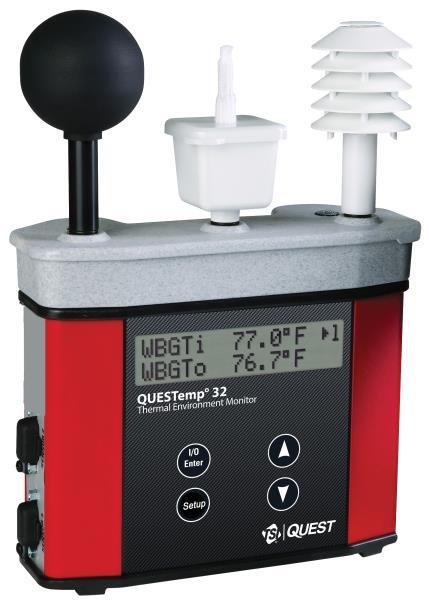
6 2 Measurements QUESTemp32 Measurements Measurements QUESTemp32 The QUESTemp32 portable area heat stress monitor computes the Wet Bulb Globe Temperature (WBGT). The WBGT is an accepted measurement for determining the heat stress level imposed on an individual in a given environment. The QUESTemp32 measures three parameters: ambient or dry bulb temperature (DB), natural wet bulb temperature (WB), and globe temperature (G). In addition to the WBGT, the QUESTemp32 measures relative humidity (RH) and computes the Heat Index (HI) or Humidex. The QUESTemp32, using inputs on the side of the instrument, has the ability to connect to two additional sensor arrays for monitoring up to three locations simultaneously. Wet Bulb Globe Temperature The WBGT is a weighted average of the three temperature sensors using the following formulas: WBGT (indoor) = 0.7WB + 0.3G (denoted as WBGTi on the display) WBGT (outdoor) = 0.7WB + 0.2G + 0.1DB (denoted as WBGTo on the display) NOTE: The resulting WBGT can be compared to indices of work-rest regimens (stay times) based upon the work loads. (See Appendix A for published heat exposure tables.)
7 3 Measurements Heat Index / Humidex Heat Index / Humidex The Heat Index is determined using the dry bulb temperature and relative humidity. Based upon charts available from the U.S. National Weather Service, Heat Index represents how an average person feels relative to climate conditions. For a constant temperature, if the humidity rises, so does the heat index. The Heat Index is defined over a temperature range of 70F - 120F (21C - 49C) and a relative humidity range of 30% - 99%. Outside of this range, the instrument will show dashes in the display for the Heat Index. The Humidex is used primarily in Canada and is very similar to the Heat Index. The values are slightly different. The Humidex is defined over a temperature range of 70F - 109F (21C - 43C) and a relative humidity range of 20% - 99%. Outside of this range, the instrument will show dashes in the display for the Humidex.
8 4 Keypad Operation Heat Index / Humidex Keypad Operation Keypad Operation The unit operates using a membrane keypad with four keys. The I/O ENTER key responds when the key is released while all other keys respond when the key is pressed. Keys I/O Enter key Up Arrow key Down Arrow key Setup key Explanation The unit turns on with a single key press. The unit turns off by holding the key down while a countdown of occurs in the lower right corner of the display. This key is also used to enter setup changes. While viewing live readings, pressing and releasing the key will cause the display to view the next available sensor bar (indicated in the upper right corner of the display). Changes which items appear in the display. Scrolls up. Changes which items appear in the display. Scrolls down. Allows changing the setup parameters. Three parameters are available: Celsius or Fahrenheit, the language, and Heat Index or Humidex. Press setup to access the parameters. Use the arrow keys to switch between the two parameters. Use the enter key to change the parameters. Press setup again to exit. Displayed Items The number in the upper right corner indicates which sensor bar s data is displayed. 1 indicates the sensor bar placed on (or attached to) the top of the instrument. Sensors 2 and 3 are labeled on the side of the unit. W indicates the weighted average which only appears if a WBGT is displayed and all three sensor bars are attached.
9 5 Displayed Items Heat Index / Humidex The following measurements can be accessed on the display: Screen 1: WET (Wet bulb) DRY (Dry bulb) WET 80.5º F 1 DRY 92.2º F Screen 2: GLOBE GLOBE 92.4.º F 1 Screen 3: WBGTi (Indoors) WBGTo (Outdoors) WBGTi 84.1 º F 1 WBGTo º F Screen 4: RH (Relative Humidity) H.I. or HU (Heat Index or Humidex) RH 66.2 % 1 H.I. 84.3º F
10 6 Placement for Monitoring/Testing Natural Wet Bulb Thermometer Placement Placement for Monitoring/Testing The QUESTemp 32 should be placed at a height of 3.5 feet (1.1 m) for standing individuals or 2 feet (.6 m) for seated individuals. Tripod mounting is recommended to get the unit away from anything that might block radiant heat or air flow. A ¼ "x 20 threaded bushing on the bottom of the instrument allows mounting to a standard photographic tripod. Do not stand close to the unit during sampling. Make sure that the wet bulb reservoir is filled with distilled water and that the cotton wick is clean and fully wetted. After adding water or placing the unit in a new environment, allow ten minutes for the globe and wet bulb readings to stabilize. A series of dashes appear in the display if one of the following occur: The Heat Index or Humidex is outside of its allowable range The temperature is outside of its allowable range A temperature sensor has failed Sensors Natural Wet Bulb Thermometer The natural wet bulb thermometer gives an indication of the effects of humidity on an individual. Relative humidity and air flow are taken into account by measuring the amount of evaporative cooling taking place at a thermometer covered with a moistened wick. The QUESTemp 32 uses a cotton wick immersed into a reservoir containing distilled water. DO NOT use ordinary tap water, as the contaminants that are left behind after evaporation will shorten the life of the wick and cause high readings. If the wick is discolored, it should be replaced. To replace the wick, slide the old wick off the top of the sensor. Place a new wick over the sensor, making sure that the bottom of the wick is down in the reservoir. Globe Thermometer The globe thermometer gives an indication of the radiant heat exposure on an individual due to either direct light or hot objects in the environment. This is accomplished by placing a temperature sensor inside a blackened copper sphere and measuring the temperature rise. The WBGT index is based on the response of a 6-inch diameter globe. The QUESTemp 32 uses a 2-inch diameter globe for a faster response time. The temperature of the 2-inch globe is correlated to match that of a 6-inch globe. As an option, a sensor array with a 6-inch diameter globe is available.
11 7 Sensors Dry Bulb Thermometer Dry Bulb Thermometer The dry bulb thermometer measures the ambient air temperature. This measurement is used in the outdoor WBGT calculation when a high solar radiant heat load may be present. The series of white plates surrounding the sensor shield it from radiant heat. Relative Humidity Sensor A relative humidity sensor is located in a compartment inside of the sensor bar housing. Slots in the housing allow air to circulate around the sensor.
12 8 Remote, Sensors 2 and 3 Tri-Sensor Weighted Average Remote, Sensors 2 & 3 Remote, Sensors 2 and 3 The top sensor bar (sensor 1) may be removed from the instrument and used through a remote cable. Shelter the instrument and remote the sensor bar if the measured environment is expecting heavy rain or if temperatures are above 60C. The sensor 2 and sensor 3 jacks on the side of the instrument allow simultaneous monitoring of up to three sensor arrays using connecting cables. Cable lengths of up to two hundred feet (61 meters) may be used without a decrease in accuracy provided the environment does not contain strong electromagnetic fields. The data from these arrays may be viewed separately or combined into a weighted average WBGT reading per ISO Change the displayed sensor bar by pressing and releasing the enter key. The upper right corner of the display shows the current sensor bar. 1 refers to the top sensor bar, 2 and 3 are labeled on the side of the unit, W indicates the weighted average which only appears if a WBGT is displayed and all three of the sensor bars are attached. Tri-Sensor Weighted Average Per the recommendations outlined in ISO 7243:2017, when the temperature in the space surrounding a worker is not uniform, it is necessary to determine the WBGT index at three heights corresponding to the worker's ankles, abdomen and head and perform a weighted average on those values. It is computed using the formula: WBGTw = (WBGThead + (2 x WBGTabdomen) + WBGTankles)/4 The QUESTemp 32 always assigns the top sensor bar the double weighting. This calculation is shown if a WBGT display has been selected and if 3 sensor sets are connected. Operational Check A verification module, model , may be used to check the operation of the QUESTemp. Remove the top sensor bar and plug the verification module into the top of the unit. With the QUESTemp set to read in degrees Celsius, verify that the displayed readings match those printed on the module within ±0.5C. If the readings are not within the ±0.5C tolerance, then have the unit serviced and calibrated.

13 9 Power Options 9-V Alkaline Battery Replacement Power Options Power Options There are 3 options for powering the QUESTemp 32: a 9-volt alkaline battery, a NiMH (Nickel Metal Hydride) rechargeable 6-cell battery pack, and an AC adapter. A door on the back of the unit allows the user access to the 9-volt battery. The rechargeable battery pack is located inside of the unit. If the rechargeable battery pack ever needs to be replaced, it can be accessed by removing the screws from the bottom panel of the unit. The 2-position switch located in the battery compartment must be set by the user if the power supply method is changed. The up position is for the 9 volt battery. The down position allows for either the AC adapter or the rechargeable batteries. The AC adapter will trickle charge the rechargeable batteries if they are in place or it will simply allow for line power operation of the unit. 9-volt battery 9-V Alkaline Battery Replacement WARNING: Replace batteries only in a non-hazardous environment. The 9-volt battery should be replaced or the NiMH battery pack should be recharged when the voltage drops below 6.4 volts. The battery voltage is displayed when the instrument is turned on. While turned on, the battery voltage can be displayed at any time by pressing the up or down arrow keys to move through the display until the battery voltage screen appears. If, while operating, the battery voltage drops below 6.4 volts, the display will automatically switch to the display showing the battery voltage along with a low battery message. After a low battery occurs, the unit will continue to operate for approximately 8 hours. When the battery voltage falls to 6.2 volts or below, the unit will automatically turn off. Replace only with an approved 9-volt alkaline battery. Approved 9-Volt Batteries Eveready: Energizer 522, EN22, 6LR61 Duracell: MN1604 Panasonic: 6LR61, 6AM6X Rayovac: A1604 UltraLife: U9V

14 10 Power Options NiMH Battery Pack Battery Pack NiMH Battery Pack WARNING: Recharge batteries only in a non-hazardous environment. The NiMH rechargeable battery pack is charged in the instrument using TSI s AC adapter # A discharged battery pack requires an overnight charge of 16 hours. Leaving the AC adapter plugged in for extended lengths of time or when operating the instrument will not harm the rechargeable batteries. NIMH Battery To install: Slide into case and plug in connector as shown.
15 11 Appendix A: Specifications Appendix A Appendix A: Specifications Measurements Globe, dry bulb, wet bulb, WBGTin, WBGTout, WBGT weighted average (if 3 sensor sets), relative humidity, Heat Index, Humidex. Languages Housing Temperatures given in Celsius or Fahrenheit. English, French, Spanish, Italian, German. Designed water resistant to a light rain or mist. If rain is frequent, best practice would be to remote the sensor bar and keep the instrument sheltered. Size Height 9.2 in. (23.5 cm); Width 7.2 in. (18.3 mm); Depth 3.0 in. (7.5 mm) Dimensions include mounted sensor assembly. Weight Sensor Types Accuracy 2.6 lbs. (1.2 kg) with mounted sensor assembly. Temperature: 1000 ohm platinum RTD Humidity: Integrated circuit with capacitive polymer sensor Temperature: ±0.5C between 0C and 120C Relative Humidity: ±5% between 20 to 95% (non-condensing) Operating Temperature Range Sensor Assembly: -5C to +100C Electronics: -5C to 60C Remote Sensor Bars 2 x 15-pin D-sub jacks are located on the side of the unit for plugging in one or two additional sensor bars by using remote cables up to 200 feet (61 m). The top sensor bar can also be remote with a cable.
16 12 Appendix A: Specifications Power Options Battery Life 9V alkaline, 7.2V NiMH rechargeable pack (charged in the unit), or AC adapter wall power cube (AC adaptor will operate the unit or recharge the NiMH battery pack). 9V alkaline: 140 hours Rechargeable Nickel Metal Hydride: 300 hours (Adding additional sensor bars reduces battery life.) Charge Time (NiMH Battery Pack) 16 hours (charge in the unit) Safety Approvals CE mark Product Markings Batteries The year of manufacture is determined by the third character in the instrument s serial number. A was manufactured in 2001, B in 2002, C in 2003, D in 2004 and so forth. Only the following battery types may be used: Non-rechargeable battery Type Manufacturer U9V Ultralife MN1604 Duracell 522 or EN22 or 6LR61 Energizer A1604 or BR232 Rayovac 6LR61 or 6AM6 Panasonic Rechargeable battery Integral NiMH battery pack type DC2121 The rechargeable battery may only be recharged with class 2 charger, rated 9 VDC, 1 A max.
17 13 Appendix B: Heat Exposures Tables Appendix B Appendix B: Heat Exposures Tables ACGIH Screening Criteria for Heat Stress Exposure. WBGT values in C. NOTE: According to the ACGIH s guidelines, the temperature values represent a work and rest process which is explained in the standards. Refer to the ACGIH TLV s and BEIs for specific details. Work and recovery (TLV ) Light Moderate Heavy Very Heavy 75% to 100% * 23.5* 50% to 75% * 25% to 50% % to 25% Work and recovery (Action Limit ) Light Moderate Heavy Very Heavy 75% to 100% * 20.0* 50% to 75% * 25% to 50% % to 25% *Values not specified by ACGIH have been estimated for continuity. Cited from "American Conference of Governmental Industrial Hygienists - Threshold Limit Values and Biological Exposure Indices for 2008"; Reprinted with permission from ACGIH
18 14 Appendix B: Heat Exposures Tables United States Navy Physiological Heat Exposure Limits (PHEL) Time Table (Without the presence of fuel combustion gases/fuel vapors) is displayed on the following page. The recommended working hours are shown based on a maximum of eight hours. Naval personnel will follow a category, I - VI, based upon their function. PHEL Curves (Total Exposure Time in Hours: Minutes) WBGT(F) I II III IV V VI 80.0 >8:00 >8:00 >8:00 8:00 6:35 4: >8:00 >8:00 >8:00 8:00 6:35 4: >8:00 >8:00 8:00 7:05 5:25 3: >8:00 8:00 7:45 6:25 4:55 3: >8:00 8:00 7:05 5:55 4:30 3: :00 7:45 6:30 5:20 4:05 2: :00 7:05 5:55 4:55 3:45 2: :25 6:30 5:25 4:30 3:25 2: :45 5:55 4:55 4:05 3:10 2: :10 5:25 4:30 3:45 2:50 2: :40 5:00 4:10 3:25 2:40 1: :15 4:35 3:50 3:10 2:25 1: :50 4:10 3:30 2:55 2:15 1: :25 3:50 3:15 2:40 2:00 1: :05 3:35 3:00 2:25 1:50 1: :45 3:15 2:45 2:15 1:45 1: :25 3:00 2:30 2:05 1:35 1: :10 2:45 2:20 1:55 1:25 1: :55 2:35 2:10 1:45 1:20 0: :40 2:20 2:00 1:40 1:15 0: :30 2:10 1:50 1:30 1:10 0: :20 2:00 1:40 1:25 1:05 0: :10 1:50 1:35 1:15 1:00 0: :00 1:45 1:25 1:10 0:55 0: :50 1:35 1:20 1:05 0:50 0: :40 1:30 1:15 1:00 0:45 0:30
19 15 Appendix B: Heat Exposures Tables WBGT(F) I II III IV V VI :35 1:25 1:10 0:55 0:45 0: :30 1:15 1:05 0:50 0:40 0: :20 1:10 1:00 0:50 0:35 0: :15 1:05 0:55 0:45 0:35 0: :10 1:00 0:50 0:40 0:30 0: :05 1:00 0:50 0:40 0:30 0: :00 0:55 0:45 0:35 0:25 0: :55 0:50 0:40 0:35 0:25 0: :55 0:45 0:40 0:30 0:25 0: :50 0:45 0:35 0:30 0:20 0: :45 0:40 0:35 0:25 0:20 0: :45 0:40 0:30 0:25 0:20 0: :40 0:35 0:30 0:25 0:15 0: :35 0:35 0:25 0:20 0:15 0: :35 0:30 0:25 0:20 0:15 0: :35 0:30 0:25 0:20 0:15 0: :30 0:25 0:20 0:15 0:15 0: :30 0:25 0:20 0:15 0:10 0: :25 0:25 0:20 0:15 0:10 0:05
20 16 Appendix B: Heat Exposures Tables Electrical power research institute (EPRI) The recommended working hours are shown based on a maximum of four hours. A time of 4:01 indicates greater than 4 hours. WBGT C Light Moderate Heavy 28 4:01 4:01 3: :01 4:00 2: :01 3:00 1: :01 2:00 1: :00 1:30 1: :30 1:15 0: :00 1:00 0: :30 0:53 0: :00 0:45 0: :45 0:40 0: :30 0:35 0: :15 0:33 0: :00 0:30 0: :53 0: :45 0: :38 0: :30 0: :28 0: :25 0: : : : :15 0 0
21 17 Appendix B: Accessories Appendix B: Accessories Appendix B: Accessories Sensor array with 2-inch globe Sensor array with 6-inch globe foot shielded remote sensor cable foot shielded remote sensor cable foot shielded remote sensor cable foot shielded remote sensor cable VAC to 9 VDC adapter VAC to 9 VDC adapter Verification module Tripod Replacement wicks Water bottle 2 oz User s manual
22 18 Contact/Service information Contact/Service Information Contact/Service information This section gives directions for contacting TSI Incorporated for technical information and directions for returning the QUESTemp 32 for service. Technical Support Contacts If you have any difficulty setting or operating the instrument, or if you have technical or application questions about this system, contact TSI s Technical Support. North America and Asia Pacific Telephone: (USA); (Outside USA) Fax: technical.services@tsi.com Europe, Middle East, and Africa Telephone: Fax: tsigmbh@tsi.com Service Contact Information If your instrument does not operate properly, or if you are returning the instrument for service, visit our website at for a Return Material Authorization, or contact Customer Service. North America and Asia Pacific TSI Incorporated 1060 Corporate Center Drive Oconomowoc, WI Telephone: (USA); (Outside USA) technical.services@tsi.com Europe, Middle East, and Africa TSI Instruments Ltd. Stirling Road Cressex Business Park High Wycombe, Bucks HP12 3ST United Kingdom Telephone: +44 (0) tsiuk@tsi.com
23 19 Contact/Service information Returning for Service Visit our website at and complete the on-line Return Merchandise Authorization form or call TSI at (USA) or (651) , or (International) for specific return instructions. Customer Service will need the following information: The instrument model number The instrument serial number A purchase order number (unless under warranty) A billing address A shipping address Calibration Use the original packing material to return the instrument to TSI. If you no longer have the original packing material, seal off any ports to prevent debris from entering the instrument and ensure that the display and the connectors on the instrument front and back panels are protected. This instrument is very fragile and must be packed in a manner appropriate for a precision instrument. The QUESTemp⁰ 32 Heat Stress Sensor should be examined regularly by the factory. An annual calibration is recommended. (See Service Department above.)
24 20 Warranty Warranty (For country-specific terms and conditions outside of the USA, please visit Seller warrants the goods, excluding software, sold hereunder, under normal use and service as described in the operator's manual, to be free from defects in workmanship and material for 12 months, or if less, the length of time specified in the operator's manual, from the date of shipment to the customer. This warranty period is inclusive of any statutory warranty. This limited warranty is subject to the following exclusions and exceptions: a. Hot-wire or hot-film sensors used with research anemometers, and certain other components when indicated in specifications, are warranted for 90 days from the date of shipment; b. Pumps are warranted for hours of operation as set forth in product or operator s manuals; c. Parts repaired or replaced as a result of repair services are warranted to be free from defects in workmanship and material, under normal use, for 90 days from the date of shipment; d. Seller does not provide any warranty on finished goods manufactured by others or on any fuses, batteries or other consumable materials. Only the original manufacturer's warranty applies; e. This warranty does not cover calibration requirements, and seller warrants only that the instrument or product is properly calibrated at the time of its manufacture. Instruments returned for calibration are not covered by this warranty; f. This warranty is VOID if the instrument is opened by anyone other than a factory authorized service center with the one exception where requirements set forth in the manual allow an operator to replace consumables or perform recommended cleaning; g. This warranty is VOID if the product has been misused, neglected, subjected to accidental or intentional damage, or is not properly installed, maintained, or cleaned according to the requirements of the manual. Unless specifically authorized in a separate writing by Seller, Seller makes no warranty with respect to, and shall have no liability in connection with, goods which are incorporated into other products or equipment, or which are modified by any person other than Seller. The foregoing is IN LIEU OF all other warranties and is subject to the LIMITATIONS stated herein. NO OTHER EXPRESS OR IMPLIED WARRANTY OF FITNESS FOR PARTICULAR PURPOSE OR MERCHANTABILITY IS MADE. WITH RESPECT TO SELLER S BREACH OF THE IMPLIED WARRANTY AGAINST INFRINGEMENT, SAID WARRANTY IS LIMITED TO CLAIMS OF DIRECT INFRINGEMENT AND EXCLUDES CLAIMS OF CONTRIBUTORY OR INDUCED INFRINGEMENTS. BUYER S EXCLUSIVE REMEDY SHALL BE THE RETURN OF THE PURCHASE PRICE DISCOUNTED FOR REASONABLE WEAR AND TEAR OR AT SELLER S OPTION REPLACEMENT OF THE GOODS WITH NON-INFRINGING GOODS. TO THE EXTENT PERMITTED BY LAW, THE EXCLUSIVE REMEDY OF THE USER OR BUYER, AND THE LIMIT OF SELLER'S LIABILITY FOR ANY AND ALL LOSSES, INJURIES, OR DAMAGES CONCERNING THE GOODS (INCLUDING CLAIMS BASED ON CONTRACT, NEGLIGENCE, TORT, STRICT LIABILITY OR OTHERWISE) SHALL BE THE RETURN OF GOODS TO SELLER AND THE REFUND OF THE PURCHASE PRICE, OR, AT THE OPTION OF SELLER, THE REPAIR OR REPLACEMENT OF THE GOODS. IN THE CASE OF SOFTWARE, SELLER WILL REPAIR OR REPLACE DEFECTIVE SOFTWARE OR IF UNABLE TO DO SO, WILL REFUND THE PURCHASE PRICE OF THE SOFTWARE. IN NO EVENT SHALL SELLER BE LIABLE FOR LOST PROFITS, BUSINESS INTERRUPTION, OR ANY SPECIAL, INDIRECT, CONSEQUENTIAL OR INCIDENTAL DAMAGES. SELLER SHALL NOT BE RESPONSIBLE FOR INSTALLATION, DISMANTLING OR REINSTALLATION COSTS OR CHARGES. No Action, regardless of form, may be brought against Seller more than 12 months after a cause of action has accrued. The goods returned under warranty to Seller's factory shall be at Buyer's risk of loss, and will be returned, if at all, at Seller's risk of loss. Buyer and all users are deemed to have accepted this LIMITATION OF WARRANTY AND LIABILITY, which contains the complete and exclusive limited warranty of Seller. This LIMITATION OF WARRANTY AND LIABILITY may not be amended, modified or its terms waived, except by writing signed by an Officer of Seller. Service Policy Knowing that inoperative or defective instruments are as detrimental to TSI as they are to our customers, our service policy is designed to give prompt attention to any problems. If any malfunction is discovered, please contact your nearest sales office or representative, or call TSI s Customer Service department at (USA) or +001 (651) (International).
25 TSI Incorporated Visit our website for more information. USA Tel: UK Tel: France Tel: Germany Tel: India Tel: China Tel: Singapore Tel: P/N Rev. J 2018 TSI Incorporated Printed in U.S.A.
QUESTemp 32 Thermal Environment Monitor. Operator s Manual
 QUESTemp 32 Thermal Environment Monitor Operator s Manual Copyright 5/2004 Revision B P/N 056-661 2 TABLE OF CONTENTS 1. UP AND RUNNING... 4 2. MEASUREMENTS... 5 QUESTEMP 32... 5 WET BULB GLOBE TEMPERATURE...
Market Leader. From the. From the. Robust Construction. QUESTemp o 32 User Manual. 3M Personal Safety Division 3M QUESTemp Heat Stress Monitors
 3M Personal Safety Division 3M QUESTemp Heat Stress Monitors Robust Construction From the 3M 2013. All Rights Reserved From the Market Leader QUESTemp o 32 User Manual ii TABLE OF CONTENTS TABLE OF CONTENTS
Market Leader QUESTemp o 32 User Manual
 3M Occupational Health and Environmental Safety Division 3M QUESTemp Heat Stress Monitors Robust Construction From the From the Market Leader QUESTemp o 32 User Manual 3M 2011. All Rights Reserved Copyright
AIR VELOCITY METER ALNOR MODEL AVM410 AIRFLOW INSTRUMENTS MODEL TA410
 AIR VELOCITY METER ALNOR MODEL AVM410 AIRFLOW INSTRUMENTS MODEL TA410 OPERATION AND SERVICE MANUAL P/N 1980575, REV F FEBRUARY 2016 Copyright TSI Incorporated / 2007-2016 / All rights reserved. Address
MICROMANOMETER ALNOR MODEL AXD610 AIRFLOW INSTRUMENTS MODEL PVM610
 MICROMANOMETER ALNOR MODEL AXD610 AIRFLOW INSTRUMENTS MODEL PVM610 OPERATION AND SERVICE MANUAL P/N 1980587, REV F SEPTEMBER 2014 Copyright TSI Incorporated / 2007-2014 / All rights reserved. Address
IAQ-CALC INDOOR AIR QUALITY METER MODEL 7515
 IAQ-CALC INDOOR AIR QUALITY METER MODEL 7515 OPERATION AND SERVICE MANUAL P/N 1980571, REVISION D FEBRUARY 2016 Copyright TSI Incorporated / May 2007-2016 / All rights reserved. Address TSI Incorporated
DUSTTRAK AEROSOL MONITOR SOLAR POWER KIT MODEL
 DUSTTRAK AEROSOL MONITOR SOLAR POWER KIT MODEL 854060 (USED FOR POWERING ENVIRONMENTAL ENCLOSURE MODELS MODELS 854030, 8535 AND 8537) OPERATION AND MAINTENANCE MANUAL P/N 6008416, REVISION C JUNE 2017
Rotating Vane Anemometer
 Ventilation Testing Rotating Vane Anemometer Alnor Model RVA801 AIRFLOW Model LCA301 Operation and Service Manual Copyright TSI Incorporated / 2007-2012 / All rights reserved. Address TSI Incorporated
Indoor Air Quality Meter
 Indoor Air Quality Indoor Air Quality Meter Alnor Model CF910 AIRFLOW TM Model IAQ910 Operation and Service Manual Copyright TSI Incorporated / 2007-2008 / All rights reserved. Address TSI Incorporated
IAQ-CALC TM Indoor Air Quality Meter
 ENERGY AND COMFORT Indoor Air Quality IAQ-CALC TM Indoor Air Quality Meter Model 7515 Operation and Service Manual Copyright TSI Incorporated / May 2007 / All rights reserved. Address TSI Incorporated
VELOCICALC Air Velocity Meter
 ENERGY AND COMFORT Ventilation Testing VELOCICALC Air Velocity Meter Model 9515 Operation and Service Manual Copyright TSI Incorporated / May 2007 / All rights reserved. Address TSI Incorporated / 500
Ventilation Testing. Micromanometer. Alnor Model AXD610 AIRFLOW TM Model PVM610. Operation and Service Manual
 Ventilation Testing Micromanometer Alnor Model AXD610 AIRFLOW TM Model PVM610 Operation and Service Manual Copyright TSI Incorporated / 2007-2008 / All rights reserved. Address TSI Incorporated / 500 Cardigan
DP-CALC TM Micromanometer
 ENERGY AND COMFORT Ventilation Testing DP-CALC TM Micromanometer Model 5815 Operation and Service Manual Copyright TSI Incorporated / May 2007 / All rights reserved. Address TSI Incorporated / 500 Cardigan
IAQ-CALC TM Indoor Air Quality Meter
 ENERGY AND COMFORT Indoor Air Quality IAQ-CALC TM Indoor Air Quality Meter Model 7515 Operation and Service Manual Copyright TSI Incorporated / May 2007 / All rights reserved. LIMITATION OF WARRANTY AND
Rotating Vane Anemometer
 Ventilation Testing Rotating Vane Anemometer Alnor Model RVA801 AIRFLOW Model LCA301 Operation and Service Manual Copyright TSI Incorporated / 2007-2008 / All rights reserved. Address TSI Incorporated
PRIMARY CALIBRATORS MODEL 4046/4146
 PRIMARY CALIBRATORS MODEL 4046/4146 USER S GUIDE P/N 1980512, REVISION F MARCH 2016 Copyright TSI Incorporated / 2004-2016 / All rights reserved. Address TSI Incorporated, 500 Cardigan Road, Shoreview,
Model 8026 Particle Generator
 Respirator Fit Testing Model 8026 Particle Generator Operation and Service Manual 1980319, Revision J December 2011 Model 8026 Particle Generator Operation and Service Manual 1980319, Revision J December
Model 8026 Particle Generator
 Respirator Fit Testing Model 8026 Particle Generator Operation and Service Manual 1980319, Revision H December 2010 Model 8026 Particle Generator Operation and Service Manual 1980319, Revision H December
OWNER S MANUAL. Model 9880 Intrinsically Safe Air Velocity Meter
 OWNER S MANUAL Model 9880 Intrinsically Safe Air Velocity Meter LIMITATION OF WARRANTY AND LIABILITY Seller warrants the goods sold hereunder, under normal use and service as described in the operator's
Model 8340 Intrinsically Safe VELOCICHECK Air Velocity Meter
 Ventilation Testing/Balancing Model 8340 Intrinsically Safe VELOCICHECK Air Velocity Meter Operation and Service Manual 1980076, Revision E October 2002 Model 8340 Intrinsically Safe VELOCICHECK Air Velocity
Thermo-Anenometer Model Owner s Manual
 Thermo-Anenometer Model 9850 Owner s Manual UL LISTED INTRINSICALLY SAFE FOR USE IN HAZARDOUS LOCATIONS FOR CLASS I GROUPS C AND D, CLASS II GROUPS E, F, AND G, AND CLASS III, ONLY WHEN USED WITH THE FOLLOWING
Exhaust Fan Flow Meter. Operation Manual. The ENERGY CONSERVATORY DIAGNOSTIC TOOLS TO MEASURE BUILDING PERFORMANCE
 Exhaust Fan Flow Meter Operation Manual The ENERGY Exhaust Fan Flow Meter Operation Manual The Energy Conservatory 2801 21st Ave. S., Suite 160 Minneapolis, MN 55407 612-827-1117 Fax 612-827-1051 www.energyconservatory.com
PLEASE ENSURE THE JUMP STARTER IS FULLY CHARGED PRIOR TO FIRST USE.
 PLEASE ENSURE THE JUMP STARTER IS FULLY CHARGED PRIOR TO FIRST USE.. (1) RG1000 EMERGENCY JUMP STARTER PORTABLE POWER SUPPLY (1) 3-IN-1 USB CABLE (1) RG1000 EMERGENCY JUMP STARTER PORTABLE POWER SUPPLY
ANALOG BALANCING TOOL MODELS ABT701, ABT703, ABT711, ABT713
 ANALOG BALANCING TOOL MODELS ABT701, ABT703, ABT711, ABT713 OWNER S MANUAL P/N 6002462, REV E FEBRUARY 2016 LIMITATION OF WARRANTY AND LIABILITY Copyright TSI Incorporated / 2009-2016 / All rights reserved.
Model 8345/8346/8347/8347A VELOCICALC Air Velocity Meters
 Ventilation Testing/Balancing Model 8345/8346/8347/8347A VELOCICALC Air Velocity Meters Operation and Service Manual 1980277, Revision E November 2002 Model 8345/8346/8347/8347A VELOCICALC Air Velocity
EAGL 1-Touch Laser Level
 EAGL 1-Touch Laser Level Owner s Manual GENERAL INFORMATION Thank you for buying the EAGL 1-Touch laser. Although it is very simple to use, we recommend that you read this manual before operating the laser.
Heat Shield Portable wireless WBGT meter
 > heat shield Heat Shield Portable wireless WBGT meter Highlights Quick, real-time, reliable and accurate assessment of indoor and outdoor WBGT index Real-time assessment of the PMV-PPD index (ISO7730)
7.3L POWERSTROKE BANJO BOLT KIT Fits L Powerstroke Diesel. Installation Guide
 7.3L POWERSTROKE BANJO BOLT KIT Fits 94-03 7.3L Powerstroke Diesel Installation Guide INSPECT CONTENTS OF THIS KIT THOROUGHLY BEFORE STARTING THE INSTALLATION PROCESS! IF YOU FIND A PROBLEM WITH YOUR PACKAGE:
Tachometer. English. Users Manual
 931 Tachometer Users Manual English PN 3409877 January 2009 2009 Fluke Corporation, All rights reserved. Printed in Germany. Specifications are subject to change without notice. All product names are trademarks
Thermometer models / 00831A
 Instruction Manual Thermometer models 00822 / 00831A CONTENTS Unpacking Instructions... 2 Package Contents... 2 Product Registration... 2 Features & Benefits... 3 Setup... 4 Install or Replace Batteries...
Wireless Thermometer model 00380
 Instruction Manual Wireless Thermometer model 00380 CONTENTS Unpacking Instructions... 2 Package Contents... 2 Product Registration... 2 Features & Benefits... 3 Setup... 4 Install or Replace Batteries...
Professional Weather Center
 Instruction Manual Professional Weather Center CONTENTS Unpacking Instructions... 2 Package Contents... 2 Product Registration... 2... 3... 4... 6 Setup... 7 5-in-1 Sensor Setup... 7... 8... 9... 9...10...
Four-Position Gang Charger for SAFEMTX Li-ION Battery Packs
 Four-Position Gang Charger for SAFEMTX Li-ION Battery Packs (P/N 10067285) Instruction Manual " WARNING THIS MANUAL MUST BE CAREFULLY READ BY ALL INDIVIDUALS WHO HAVE OR WILL HAVE THE RESPONSIBILITY FOR
EXHAUST FAN FLOW METER
 EXHAUST FAN FLOW METER OVERVIEW AND MANUAL THE ENERGY CONSERVATORY WARRANTY EXPRESS LIMITED WARRANTY Seller warrants that this product, under normal use and service as described in the operator s manual,
Fifth Wheel Power Hitch Operations Manual
 Fifth Wheel Power Hitch Operations Manual ITD1253 Fifth Wheel Power Hitch 208 587 7960 www.intheditch.com This page is intentionally left blank. Operations Manual 1 TABLE OF CONTENTS TABLE OF CONTENTS...
GC-1. Roof and Gutter De-Icing Control Installation and Operating Instructions FOR EXTERIOR INSTALLATION ONLY
 GC-1 Roof and Gutter De-Icing Control Installation and Operating Instructions FOR EXTERIOR INSTALLATION ONLY GENERAL INFORMATION The GC-1 heating cable controller has been designed and manufactured for
SPC Series. Digital Scale. Operation Manual
 SPC Series Digital Scale Operation Manual Revision 1.0 August 17, 2000 ! WARNING Use only the AC adapter which comes with the scale. Other adapters may cause damage. Internal service to this product should
This manual covers the following model:
 www.skcltd.com chek-mate Air Flowmeter Operating Instructions This manual covers the following model: 375-07550 Purchase Details and Service Record Thank you for choosing an SKC product. Your purchase
Infrared Thermocouple Probe
 80PK-IR Infrared Thermocouple Probe Instruction Sheet 80PK-IR INFRARED TEMPERATURE PROBE 0 to 500 F / -18 to 260 C INTRODUCTION The Fluke 80PK-IR Infrared Thermocouple Probe (the probe) is a noncontact
PVI 1800/PVI Residential/Commercial Grid-Tied Photovoltaic Inverter WARRANTY MANUAL. Subject to Change REV , Solectria Renewables
 PVI 1800/PVI 2500 WARRANTY MANUAL Residential/Commercial Grid-Tied Photovoltaic Inverter 2009, Solectria Renewables Subject to Change REV 10.09 1 Product Warranty & RMA Policy 1.1 Warranty Policy The Solectria
WIRING DIAGRAMS FOR BRIDGE CONTROL PANELS
 WIRING DIAGRAMS FOR BRIDGE CONTROL PANELS Bridge W/D's Panel Part # Page No. Nema-4/12 1-Speed 444231-** 2 Nema-4/12 1-Speed with Soft-Start 444711-** 3 Nema-4/12 2-Speed 444232-** 4 Nema-4/12 2-Speed
COMMAND SERIES 410-L T L T T T L06R RS PRODUCT MANUAL
 COMMAND SERIES 40-L06 40-T09 420-L06 420-T06 420-T09 420-T5 420-L06R 420-009RS PRODUCT MANUAL TABLE OF CONTENTS COMMAND REFERENCE GUIDE INTRODUCTION Command Reference Guide 3 Physical Characteristics &
Humidity Monitor model 00619
 Instruction Manual Humidity Monitor model 00619 CONTENTS Unpacking Instructions...2 Package Contents...2 Product Registration...2 Features & Benefits...3 Setup...3 Measurement Units...4 Placement Guidelines...4
HR-20P Pneumatically Controlled Pressure Regulator
 HR-20P Pneumatically Controlled Pressure Regulator Instruction and Service Manual Hydroplex Corporation 230 West Gloria Switch Rd. Lafayette, LA 70507 337-233-0626 www.hydroplexpumps.com I. General Instructions
Model NTX7 Series Automatic Battery Charger User s Manual Rev. 1.0 October 17, 2006
 B R A N D Model NTX7 Series Automatic Battery Charger User s Manual Rev. 1.0 October 17, 2006 For Sales, Support and Service phone: 407-331-4793 fax: 407-331-4708 website: www.xenotronix.com email: information@xenotronix.com
II DISTRIBUTION & SUBSTATION TYPE C
 CapCheckIII DISTRIBUTION & SUBSTATION TYPE Ca p a c i t o r C h e c ke r Operating & Instruction Manual 1475 Lakeside Drive Waukegan, Illinois 60085 U.S.A. 847.473.4980 f a x 8 4 7. 4 7 3. 4 9 8 1 w e
Wireless Thermometer model 00782W
 Instruction Manual Wireless Thermometer model 00782W CONTENTS Unpacking Instructions... 2 Package Contents... 2 Product Registration... 2 Features & Benefits... 3 Setup... 4 Install or Replace Batteries...
INW Panel Meter Reading an INW PT12 Sensor
 INW Panel Meter Reading an INW PT12 Sensor PROUDLY MADE IN THE USA ISO 9001:2008 Certified Company Table of Contents Introduction...5 What is an INW Panel Meter for an INW PT12 Smart Sensor?...5 Initial
362 Clamp Meter. Users Manual
 362 Clamp Meter Users Manual PN 3622678 August 2010, Rev. 1, 4/13 2010, 2013 Fluke Corporation. All rights reserved. Printed in China. Specifications are subject to change without notice. All product names
Respirator Fit Testers
 Respirator Fit Testing Respirator Fit Testers (Manual and Automatic Versions) User s Manual P/N 6002712, Revision C December 2010 U.S. and International patents pending. Copyright TSI Incorporated / 2010
Temperature Probe, Battery (installed), Instruction Sheet, Quick Reference Card and Warranty Card.
, Instruction Sheet, Quick Reference Card and Warranty Card.") 80T-IR Infrared Temperature Probe Instruction Sheet Introduction The Fluke 80T-IR Infrared Temperature Probe (the probe) is a noncontact temperature measurement accessory for use with a test instrument
80T-IR Infrared Temperature Probe Instruction Sheet Introduction The Fluke 80T-IR Infrared Temperature Probe (the probe) is a noncontact temperature measurement accessory for use with a test instrument
Thermometer model 00826
 Instruction Manual Thermometer model 00826 CONTENTS Unpacking Instructions... 2 Package Contents... 2 Product Registration... 2 Features & Benefits... 3 Setup... 4 Install or Replace Batteries... 4 Set
Sample Pro 3/4" Portable MicroPurge Pump. User's Guide P/N REV The World Leader in Air Powered Pumps
 PATENT PENDING Pro 3/4" Portable MicroPurge Pump User's Guide P/N 959 REV. -8-03 The World Leader in Air Powered For Remediation, Landfills and Ground Water Sampling Ground water Sampling Remediation,
STAINLESS STEEL FORGED FITTINGS 3000lb 304/304L & 316/316L Forged Stainless Steel Fittings Product Specifications
 STAINLESS STEEL FORGED FITTINGS 3000lb 304/304L & 316/316L Forged Stainless Steel Fittings Product Specifications Manufactured in ISO9000:2000 Facility Manufactured to ASTM/ASME A182/SA182 Items conform
SPC-PANEL Simplex, Single Phase Pump Control Panel
 Pump Installation and Service Manual SPC-PANEL Simplex, Single Phase Pump Control Panel Pump Controls for 2 HP Grinder Pumps NOTE! To the installer: Please make sure you provide this manual to the owner
A Member of the. Integrated Metering Technologies
 I n s t a l l a t i o n M a n u a l A Member of the Integrated Metering Technologies 1.0 General and Safety Do not install, operate or maintain this flow meter without reading, understanding and followingthe
AXD 530 MicroManometer
 OWNER S MANUAL AXD 530 MicroManometer A TSI Company Table of Contents Features 2 Using the AXD530 Safely 3 Getting Started 4 Installing Batteries 4 Preparing the Instrument 4 Attaching the Optional Pitot-Static
Charging with AC (wall) Charger
 Charger") Kodiak User Guide Unpacking Your Kodiak Included in the box: A. Kodiak generator B. AC Charger Charging Your Kodiak (see diagram on opposite side for port locations) Charging with Solar The Kodiak provides
Kodiak User Guide Unpacking Your Kodiak Included in the box: A. Kodiak generator B. AC Charger Charging Your Kodiak (see diagram on opposite side for port locations) Charging with Solar The Kodiak provides
Buck BioAire Model B520 Instruction Manual
 A.P. BUCK, INC. Buck BioAire Model B520 Instruction Manual A.P. BUCK, INC. 7101 Presidents Drive Suite 110 Orlando, FL 32809 USA Tel 1-800-330-2825 407-851-8602 Fax 407-851-8910 apbuck@apbuck.com www.apbuck.com
Thermometer models 02023/02028/02053/02054
 Instruction Manual Thermometer models 02023/02028/02053/02054 CONTENTS Unpacking Instructions... 2 Package Contents... 2 Product Registration... 2 Features & Benefits... 3 Setup... 4 Set the Time & Units...
PVI 60KW, PVI 82KW, PVI 95KW
 PVI 60KW PVI 82KW PVI 95KW WARRANTY MANUAL Commercial, Grid-Tied Photovoltaic Inverters 2008, Solectria Renewables LLC Subject to Change DOC-020099 rev 024 1 1 Product Warranty & RMA Policy Warranty Policy
Electrometer NiCad Battery Replacement
 Electrometer NiCad Battery Replacement Table of Contents NOTE: Although this manual is provided by Standard Imaging as a reference, battery replacement by anyone other than a trained Standard Imaging employee
Window Thermometer models / / 00423
 Instruction Manual Window Thermometer models 00305 / 00306 / 00423 CONTENTS Unpacking Instructions... 2 Package Contents... 2 Product Registration... 2 Features & Benefits... 3 Setup... 3 Placement Guidelines...
DISCOVER ADVANCED ENERGY SYSTEM - AES WARRANTY POLICY
 DISCOVER ADVANCED ENERGY SYSTEM - AES WARRANTY POLICY DOCUMENT NUMBER 885-0008 REV B Oct 23, 2017 READ THIS DOCUMENT CAREFULLY: Discover has spent over 10 years developing what we know to be some of the
FREQUENTLY ASKED QUESTION SERIES. BANJO BOLTS WHY THE BAD RAP? 6.0L Powerstroke Diesel. Last Updated: 7/2/2018 Page 1 of 3 S Diesel, LLC
 FREQUENTLY ASKED QUESTION SERIES BANJO BOLTS WHY THE BAD RAP? 6.0L Powerstroke Diesel Last Updated: 7/2/2018 Page 1 of 3 S Diesel, LLC Ihave been getting a bunch more comments and questions from customers
INSTALL GUIDE Dodge/RAM 5.7L HEMI
 INSTALL GUIDE 2009-2017 Dodge/RAM 5.7L HEMI TABLE OF CONTENTS 3 GETTING STARTED 3 PARTS LIST 4 INSTALLATION INSTRUCTIONS 4 REMOVING THE STOCK INTAKE ASSEMBLY 6 INSTALLING THE AIR FILTER 7 INSTALLING THE
THWD-3 and TH-3 Relative Humidity and Temperature Meters
 THWD-3 and TH-3 Relative Humidity and Temperature Meters User Manual 99 Washington Street Melrose, MA 02176 Phone 781-665-1400 Toll Free 1-800-517-8431 Visit us at www.testequipmentdepot.com 3 THWD-3 and
Thermometer models 02023, 02028, 02029
 Instruction Manual Thermometer models 02023, 02028, 02029 CONTENTS Unpacking Instructions... 2 Package Contents... 2 Product Registration... 2 Features & Benefits... 3 Setup... 4 Set the Time, Date & Units...
Be Strong. Assembly Manual Commercial Series Bike U916. Model: U916. P/N: Rev D (03/28/07)
") Be Strong. Assembly Manual Commercial Series Bike U916 Model: U916 P/N: 001-6883 Rev D (03/28/07) preface Thank you for purchasing the Nautilus Commercial Series U916 bike. For more than 30 years Nautilus,
Be Strong. Assembly Manual Commercial Series Bike U916 Model: U916 P/N: 001-6883 Rev D (03/28/07) preface Thank you for purchasing the Nautilus Commercial Series U916 bike. For more than 30 years Nautilus,
User's Guide. CO 2 Meter. Model CO250
 User's Guide CO 2 Meter Model CO250 Introduction Congratulations on your purchase of this Model CO250 Meter. This meter measures CO2 (Carbon Dioxide) levels, air temp., dew point, wet bulb temperature
Buck BioSlide Model B1020 Instruction Manual
 A.P. BUCK, INC. Buck BioSlide Model B1020 Instruction Manual 10-20LPM Constant Flow Bioaerosol Sampling Pump For Microscope Slides Page Quick Guide 3 Product Description and Features 4 A.P. BUCK, INC.
Manufacturing Facility is ISO9001:2000. Welded Steel Pipe Conform to ASTM A53. Threads Conform to ASME B1.20.1
 STEEL NIPPLES S40 & S80 Steel Nipple Product Specifications Manufacturing Facility is ISO9001:2000 Welded Steel Pipe Conform to ASTM A53 Threads Conform to ASME B1.20.1 800-678-2544 800-678-0857 www.msi-products.com
LUBRICATOR GUN INSTRUCTIONS-PARTS LIST. 10,000 psi (700 bar) Maximum Delivery Pressure. Detachable-type
 Maximum Delivery Pressure. Detachable-type") INSTRUCTIONS-PARTS LIST 306 460 INSTRUCTIONS This manual contains important warnings and information. READ AND KEEP FOR REFERENCE. Rev. E Supercedes D Detachable-type LUBRICATOR GUN 10,000 psi (700 bar)
INSTRUCTIONS-PARTS LIST 306 460 INSTRUCTIONS This manual contains important warnings and information. READ AND KEEP FOR REFERENCE. Rev. E Supercedes D Detachable-type LUBRICATOR GUN 10,000 psi (700 bar)
CRD610 Automatic Fitting Inserter
 CRD610 Automatic Fitting Inserter OPERATIONS MANUAL VERSION 1.2 LAST EDITED 12.12.2018 cleanroomdevices.com 1 Table of Contents Title Page. 1 Table of Contents...2 1.0 General Product & Safety Information....3
DIGIGAUGE P R E S S U R E D I S P L A Y S Y S T E M I N S T R U C T I O N M A N U A L
 DIGIGAUGE P R E S S U R E D I S P L A Y S Y S T E M I N S T R U C T I O N M A N U A L Thank you for purchasing DigiGauge by ZAETECH Disclaimer DigiGauge is for show and off road use only. By using this
WARRANTY POLICY. Grid-Tied Photovoltaic Inverters. Revision D. 2014, Solectria Renewables, LLC DOCIN
 WARRANTY POLICY Revision D 2014, Solectria Renewables, LLC DOCIN-070360 1 Product Warranty & RMA Policy 1. Warranty Policy Warranty Registration: It is important to have updated information about the inverter
Installation Guide Smart-UPS On-Line External Battery Pack XBP48RM1U-LI
 Installation Guide Smart-UPS On-Line External Battery Pack XBP48RM1U-LI Important Safety Messages Read the instructions carefully to become familiar with the equipment before trying to install, operate,
OPERATING INSTRUCTIONS AND PARTS LIST BRIDGE DRIVE GEAR CASE
 OPERATING INSTRUCTIONS AND PARTS LIST BRIDGE DRIVE GEAR CASE GENERAL Units are intended to be used within 30 days after receipt. If they are to be stored for a longer period of time, contact the factory
 OPERATING MANUAL: L/S VARIABLE-SPEED MODULAR DRIVES Model Nos. Pump Drive 07559-00 with Pump Head 07516-00 07559-00 07559-05 07559-10 07559-15 A-1299-7331 Edition 01 (US & Canada only) Toll Free 1-800-MASTERFLEX
CLEAN ROOM DEVICES, LLC "WHERE TUBING AND FITTINGS COME TOGETHER"
 CLEAN ROOM DEVICES, LLC "WHERE TUBING AND FITTINGS COME TOGETHER" CRD400 Fitting Inserter OPERATIONS MANUAL VERSION 3.1 LAST EDITED 03.08.11 DOCUMENT NUMBER 001 cleanroomdevices.com 1 Table of Contents
INSTRUCTION MANUAL SURFACE RESISTIVITY METER SRM-110
 Pinion Products Corporation Inc. ESD and Ionization Instruments for Industry 32086 Share 28 Road Los Fresnos, TX 78566 (956) 233-8774 / FAX (956) 233-8924 Email: sales@pinionproducts.net www.pinionproducts.net
Lubricator Gun: 10,000 psi (700 bar) Maximum Delivery Pressure when disconnected from Dispenser
 Maximum Delivery Pressure when disconnected from Dispenser") INSTRUCTIONS-PARTS LIST 30 455 INSTRUCTIONS This manual contains important warnings and information. READ AND KEEP FOR REFERENCE. Rev. C Supercedes B Hand-Operated Portable Grease Dispenser Buckshot Luber
INSTRUCTIONS-PARTS LIST 30 455 INSTRUCTIONS This manual contains important warnings and information. READ AND KEEP FOR REFERENCE. Rev. C Supercedes B Hand-Operated Portable Grease Dispenser Buckshot Luber
Installation / Operation Instructions Sunnex ORION Series Exam Lights
 Installation / Operation Instructions Sunnex ORION Series Exam Lights OR-120 OR-127 OR-220 OR-227 Models: OR-300 OR-400 OR-500 OR-600 1. APPLICATIONS The Sunnex ORION Series light was designed specifically
MODEL V-24 OWNER'S MANUAL PARTS
 OWNER'S MANUAL MODEL V-24 PARTS NOTE: MANUAL including SPECIFICATIONS, subject to change without notice All ratings specified are based on structural factors only, not vehicle capacities or capabilities.
IN120L / IN120LB / TM120L/TM120LB IN2400L
 IN120L / IN120LB / TM120L/TM120LB IN2400L Contents Page 2, Equipment Safety Guidelines Page 3, Introduction Page, 4-5 Charging Page, 6-7 Operating Instructions Page 8, Battery Performance Page 9, Battery
The Ultimate Smart Grid Solution INSTRUCTION MANUAL
 ECOWISE EW20/1 EW30/1 The Ultimate Smart Grid Solution INSTRUCTION MANUAL Welcome! Congratulations on selecting the ECOWISE unit to manage your energy supply needs. ECOWISE units reduce the amount of electric
HighLuxV2-Zenigata Series
 Features Light source: 3.6W Zenigata power LED Source life: More than 30,000 hours Low heat, no UV or IR light radiation Homogeneous and well defined illumination Highest Luminous Efficacy: 50 lm/watt
Firstmate Installation Manual and User's Guide May, 2003
 Firstmate Installation Manual and User's Guide May, 2003 Aqualogic Marine, Inc. 506-D Terry Lane - Washington - Missouri - 63090 Warning No user serviceable parts are located inside your Firstmate unit.
PowerFLEX Module Limited Warranty Program
 PowerFLEX Module Limited Warranty Program Global Solar provides a limited warranty applicable to the Global Solar PowerFLEX TM Modules listed below: PowerFLEX TM 6-Meter - - FG-1 BT(M or N)-(275 or 300)
i n s t r u c t i o n m a n u a l
 i n s t r u c t i o n m a n u a l 8006 Six-Station AC Timer Residential/Light Commercial Independent Program Irrigation Controllers Installation, Programming and Operating Instructions Features Operates
The Ultimate Smart Grid Solution INSTRUCTION MANUAL
 ECOWISE EW30/1 The Ultimate Smart Grid Solution INSTRUCTION MANUAL Welcome! Congratulations on selecting the ECOWISE unit to manage your energy supply needs. ECOWISE units reduce the amount of electric
SGS Galson Laboratories, Inc. Equipment Rental, FreePumpLoan & FreeSamplingBadges (3-in-1) Agreement
 Agreement") SGS Galson Laboratories, Inc. Equipment Rental, FreePumpLoan & FreeSamplingBadges (3-in-1) Agreement This Equipment Rental, FreePumpLoan & FreeSamplingBadges (3-in-1) Agreement (the Agreement ) is entered
SGS Galson Laboratories, Inc. Equipment Rental, FreePumpLoan & FreeSamplingBadges (3-in-1) Agreement This Equipment Rental, FreePumpLoan & FreeSamplingBadges (3-in-1) Agreement (the Agreement ) is entered
HATCHGRIP Installation Instructions/Operation and Maintenance Manual
 HATCHGRIP Installation Instructions/Operation and Maintenance Manual Models: HTG-PCG Contact Information Table of Contents: Safety Precautions... 2 Product Information... 2 Operation... 3 Installation
Phase Sequence Tester
 User's Guide Phase Sequence Tester Model 8000 Introduction Congratulations on your purchase of the Extech Model 0800 Phase Sequence Tester. This handheld instrument detects the phase sequence of three-phase
INSTRUCTIONS FOR HAZ-DUST RESPIRATORY PARTICULATE AIR MONITOR MODEL HD-1100
 INSTRUCTIONS FOR HAZ-DUST RESPIRATORY PARTICULATE AIR MONITOR MODEL HD-1100 Environmental Devices Corporation 4 Wilder Drive Bldg. 15 Plaistow, NH 03865 Tel: (603) 378-2112 Fax: (603) 378-2113 E-mail:
User s Manual. Model MDS-30. User s Manual. A Portable Actuator for Remotely Operating Cutler Hammer Magnum DS Breakers.
 A Portable Actuator for Remotely Operating Cutler Hammer Magnum DS Breakers 1.0 Arc-blast Hazards User s Manual for Model MDS-30 2.0 Safety Information 2.1 Finger pinch points 2.2 Strong magnets 3.0 Battery
Installation Power Management Unit Battery Cables and Battery Harness
 Installation Power Management Unit Battery Cables and Battery Harness Important Safety Messages SAVE THESE INSTRUCTIONS - This manual contains important instructions that should be followed during installation
AC Irrigation and Propagation Controllers I Four Station, 5006-I and 5006-IP Six Station
 AC Irrigation and Propagation Controllers 5004-I Four Station, 5006-I and 5006-IP Six Station I N S T R U C T I O N M A N U A L Table of contents Introduction 1 1. Specifications 1 2. Controller Mounting
Smart Battery Charger GPC-35-MAX GPC-45-MAX GPC-55-MAX GPC-75-MAX GPC-100-MAX. Owner s Manual
 Smart Battery Charger GPC-35-MAX GPC-45-MAX GPC-55-MAX GPC-75-MAX GPC-100-MAX Owner s Manual Table of Contents Important Safety Instructions 2 Features 3 Installation Guidelines 5 Warranty 8 1.0 Important
SUNTURA SOLAR TRACKER
 WindyNation SUNTURA SOLAR TRACKER SOT-TRKS-NF User s Manual Page 1 of 10 WindyNation 08/09/2012 Table of Contents 1 Introduction... 3 1.1 Limited Warranty... 3 1.2 Restrictions... 3 1.3 Warranty Claims