PHOENIX TACHOMETER WITH OLED DISPLAY
|
|
|
- Christiana Ashley Leonard
- 5 years ago
- Views:
Transcription


1 PHOENIX TACHOMETER WITH OLED DISPLAY REV A
2 PROGRAMMABLE TACHOMETER WIRING Standalone tachometers with AMP plugs are incandescent perimeter, backlit or LED backlit. Incandescent bulbs will be in the access holes installed into the circuit board. DIP-switch settings are not required on tachometers. 3-3/8 and 4-3/8 are the same configuration. Programming/button wiring is different for tachometers with and without OLED display screen. INCANDESCENT 194 BULBS DIP SWITCH AND PROGRAMMING ACCESS 12-PIN AMP PLUG BACK CLAMP MOUNTS PIN AMP PLUG PLUG # PIN # PIN COLOR FUNCTION 1 RED 12V+ SWITCHED 1A 2 GR/YEL NOT USED 3 ORANGE NOT USED 4 YELLOW NOT USED 5 TAN NOT USED 6 WHITE LIGHTING 7 BLACK GROUND 8 VIOLET TACH SIGNAL 9 GREY NOT USED 10 BLUE NOT USED 11 GREEN NOT USED 12 BROWN* REMOTE BUTTON* * NOT USED ON TACHOMETER WITHOUT OLED DISPLAY LIGHTS/DIMMER PCM/CDI PCM/CDI MAY REQUIRE PULL UP RESISTOR (SEE LATER IN THIS BOOK) IGNITION COIL, CONNECT TO NEGATIVE SIDE OF THE COIL GROUND OLED MODELS ONLY: REMOTE BUTTON ONE SIDE TO GAUGE, ONE SIDE TO GROUND. MOMEN - TARY ON
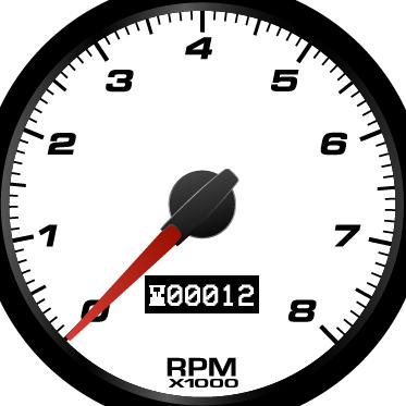
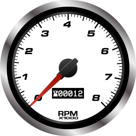
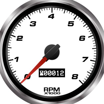
3 INSTALLATION BASICS: -Use a minimum of 20 gauge insulated, stranded wire, all connections should be connected with a crimp connection or solder and heat shrink. -Keep speed signal wire(s) away from potential noise sources like ignition wires, tach signal wires, fan motors, pumps etc. -Studded speedometers use #8 studs, use applicable eye terminals for wiring. -Use a maximum of 5A fuse for the entire cluster, this is usually already in your fuse block Commonize wiring, ground, power and lights can be common on all gauges and daisy chained OLED DISPLAY TACHOMETERS WITH ANALOG POINTERS With all of the features packed into NVU Phoenix platform tachometers, we have divided them into different menus. Your tach has a main RUN Menu, and a SETUP menu. The RUN menu utilizes the features used during normal operation. The SETUP menu stores all of the items that are setup during the installation process. Items can be changed any time after, if desired, and are separate to prevent inadvertently changing them during normal use. RUN Menu Functions Features can be accessed in the run menu during normal operation with the key on. To scroll to the various displays in the OLED screen, use a short push or tap of the remote button. BLANK SCREEN: We have included a blank screen option to give the user an opportunity to not display any information. HOURMETER: Displays the total hours the vehicle has been running. This is not resettable. This function is useful to track servicing the vehicle especially when idling for long periods is common such as in commercial, fleet and emergency vehicles, or when a speedometer or odometer is not used in the vehicle.
4 RUN MENU-CONTINUED SERVICE HOURS: User resettable hourmeter to track engine use similar to a trip odometer. It is identified by the SH on the left side of the screen This can be reset just like a trip odometer, while in this screen hold down the set button until zero is displayed. The hours will count up from there. This can be reset at any time and can also be used for tracking time to a destination as well as servicing the vehicle. PEAK RPM is displayed on the following screen. This will store and allow the user to view the peak RPM achieved since the last reset. This can be reset any time by holding in the programming button until all zeros are displayed. This may be reset at any time and the last peak RPM will be stored until reset. BOOT or SETUP MENU. This area of the tachometer is used during set-up and any of the settings can be changed at any time. The items in the setup menu are hidden in this sub-menu to avoid inadvertently changing settings during normal use. To enter the setup menu, hold in the button while turning on the key (you do not have to start the vehicle if you do not want to). The setup menu screen will be displayed. To exit the setup menu, turn the key off, and restart normally.
5 BOOT MENU, CONTINUED SET CYLINDERS Allows the user to set the tachometer to accommodate different number of cylinders for their vehicle. See notes on connecting to GM PCMs for later in this manual if required. Tachometers ship from the factory preset for 8 cylinders, all set up for 4 stroke engines. Custom ranges and inputs are available for diesel and 2-stroke engines. To set the number of cylinders, hold in the button until the current setting is displayed. Scroll to the desired setting and hold until the confirmation message is visible. Select yes or no, and hold in the button until the setting is saved. INPUT FILTER. Generally this setting does not require and adjustment. You may change the settings if you are having difficulty with noise in your signal or sharp spikes. To enter the filter mode, hold in the button until the settings are shown. There are 3 options low L medium M and high H. You can experiment to see if the filters aid your signal. The changes can be made with the vehicle running so you can see the difference in settings. To change the setting, scroll to L, M or H and hold in the button. Once you are at the desired setting, hold in the button until the confirmation message is displayed, and select Yes or NO, hold in the button to select. SAVED! will confirm the setting has been changed and now the filter is set. SHIFT ALERT. The shift alert is built-into the OLED display and will give the driver a warning of when to shift based on RPM. The alert is a 3 stage display, warning 1,000 and 500 RPM before the shift point, and the actual shift point. This can be used to pre-set shift points for optimal horsepower, mileage or to prevent overrevving the engine, it is up to the driver to decide how they would like it to be set up. The shift alert can also be disabled by setting to zero RPM.
6 BOOT MENU, CONTINUED SHIFT ALERT, CONTINUED. To enter the shift alert menu, hold in the button while at the screen. The current shift point will be displayed (0000 for no shift alert). Tap the button to change the first digit which will be highlighted. Each tap will advance the digit by one number. Hold the button in to advance to the next digit and follow the same sequence until you have the desired setting. At the last digit, once satisfied, hold in the button to enter the verification menu. Select YES or NO and hold in the button. Once saved, the display will show the current shift setting and SAVED! HOW THE SHIFT ALERT DISPLAYS INFORMATION: This is active all of the time when in any menu window during normal operation. For the setting above, 5,500 RPM, the display with indicate the engine is 1,000 RPM before the shift point with a single arrow on the screen: 500 RPM before the shift point 2 arrows will be displayed: At the desired, set shift point, the screen will invert creating a highly visible sign that the engine is at the RPM designated to shift, the word SHIFT will display: The arrows will operate in the inverse as RPM decreases. The shift point setting can be changed at any time desired, or disabled by setting the shift alert to all zeros (0000). PROGRAM VERSION. This displays the current software version installed in the unit.
7 TACHOMETER SIGNALS IGNITION COIL Even today the most common ignition source is the traditional coil. Use the negative side of the coil when using a distributor style with traditional points or electronic ignition. The signal is a high-voltage pulsed signal. COIL ON PLUG (COP) Is essentially the same as a traditional coil with the exception of each cylinder having its own individually fired coil. This setup is used in conjunctions with PCMs. If you use the trigger on a COP the tachometer should be set to 1 cylinder (2PPR) operation. HEI/ INTEGRATED CDI DISTRIBUTOR incorporates the coil and either points or electronic ignition all into the distributor. There is either a high voltage or 12V square wave signal TACH output labelled on the side of the tach. CDI/ELECTRONIC IGNITION/MSD BOX. This type of ignition box provides a multiple spark to each cylinder to improve performance. The unit will have a tach output terminal that sends a 12V square wave signal. Do not connect your tachometer to the coil or it will react erratically with the multiple sparks per cylinder. GM PCM have an open collector signal tach output, consult your PCM documentation for exact pin. You will need a 10K-ohm pullup resistor to change the open collector signal to a square wave (see diagram ). This is installed to pull up the signal between the power and tach signal from the PCM. All GM PCMs output a 4 cylinder signal regardless of number of cylinders or if it is gas or diesel. TACH SIGNAL 12V SWITCHED 10K OHM RESISTOR GROUND LIGHTS CRANK TRIGGER type generates an AC sinewave signal by using a magnetic sender to count the number of teeth. Your NVU tachometer may require bypassing of the internal filter call for more information. You will also need to calibrate the PPR (programmable models with OLED) (pulse per revolution) to the number of teeth or magnets on the flywheel ALTERNATOR W TERMINAL also outputs an AC sinewave like the above crank trigger, a reference tachometer is the best way to determine the exact RPM, then the tach can be properly calibrated by setting the PPR (programmable models with OLED)
8 THANK YOU Thank you for choosing NVU products. We strive to provide the finest quality and designed products available on the market. TECH SUPPORT DO NOT contact the retailer for tech/installation assistance. The retailer will not have the technical expertise to know the contents of the kit or the nuances of installing in your specific vehicle. We are here to help! Contact NVU directly, our qualified installation technicians have the knowledge of the product and its installation to help you get going right away. If you need technical assistance please feel free to call us at or us at NVU 5-YEAR WARRANTY Service can be obtained during the normal warranty period by contacting New Vintage and obtaining a Return Authorization Number (RZA#). New Vintage will repair or replace any item found to be defective and return ship to no cost via ground or post office services. Other shipping/international services will be applied at additional cost. Buyer is responsible for shipping to New Vintage for warranty repair. Return shipping will be the responsibility of the customer if the product is found to be damaged or out of warranty. An RZA number must be obtained and proper return/warranty form accompanied with the product. MISSING ITEMS/RETURNS Hey, we all make mistakes, no problem just give us a call if you believe that you are missing something in the box. DO NOT CONTACT THE RETAILER, as they will not have the complete packing list or the pertinent information to properly help you. We will take care of it for you. Missing items/returns must be processed within 15 days of end user receiving the product. All returned must be shipped back to the place of purchase. Any return shipping costs to New Vintage are the responsibility of the purchaser. An RZA number must be obtained and proper return/warranty form accompanied with the product. A restocking fee not to exceed 10% may be applied to items that must be repackaged. Any item returned in a non-usable condition will be returned or charged to the customer. Missing items must be reported within 15 days of receiving the product. Items found to be missing will be shipped via ground or postal service at no charge. Expedited/international shipping options are available at an additional charge. It is the policy of New Vintage to quickly replace any items that may be missing in a timely manner but not to overnight or expedite shipping in any way at no cost.
PHOENIX SPEEDOMETER INSTALLATION INSTRUCTIONS
 PHOENIX SPEEDOMETER INSTALLATION INSTRUCTIONS PHOENIX-IMI-1031418 NVU Phoenix platform speedometers offer features found in complete clusters, OE instrument systems and data loggers, all in a standalone
CUSTOM INSTRUMENT KIT INSTALLATION INSTRUCTIONS
 CUSTOM INSTRUMENT KIT INSTALLATION INSTRUCTIONS REV 1 01.3019 Advanced feature speedometers offer features found in complete clusters, OE instrument systems and data loggers, all in a standalone unit.
FULL SWEEP STEPPER MOTOR INSTRUMENT KIT INSTRUCTION MANUAL 1969,REDLINE, 2020 SERIES
 FULL SWEEP STEPPER MOTOR INSTRUMENT KIT INSTRUCTION MANUAL 1969,REDLINE, 2020 SERIES REVB071211 INDEX 3-3/8 PROGRAMMABLE SPEEDOMETER 3-3/8 TACHOMETER 2-1/16 GAUGES TEMPERATRURE SENDER PRESSURE SENDER PROGRAMMABLE
NEW VINTAGE INSTRUMENT AND GAUGE KIT INSTALLATION INSTRUCTIONS
 NEW VINTAGE INSTRUMENT AND GAUGE KIT INSTALLATION INSTRUCTIONS REV.01-033113 INDEX THE BASICS CLUSTER INSTALLATION TACHOMETER OPERATION SPEEDOMETER OPERATION TROUBLESHOOTING WIRING DIAGRAM pg.2 pg. 2 pg.
NEW VINTAGE INSTRUMENT AND GAUGE KIT INSTALLATION INSTRUCTIONS 3-1 INSTRUMENT KITS SPEEDO/TACH KITS REV
 NEW VINTAGE INSTRUMENT AND GAUGE KIT INSTALLATION INSTRUCTIONS 3-1 INSTRUMENT KITS SPEEDO/TACH KITS REV.01-032912 INDEX THE BASICS FUNCTIONS AND SENDERS TACHOMETER OPERATION SPEEDOMETER OPERATION TROUBLESHOOTING
NEW VINTAGE INSTRUMENT AND GAUGE KIT INSTALLATION INSTRUCTIONS 3-1 INSTRUMENT KITS SPEEDO/TACH KITS 3-3/8 STUDDED SPEEDOMETERS REV.
 NEW VINTAGE INSTRUMENT AND GAUGE KIT INSTALLATION INSTRUCTIONS 3-1 INSTRUMENT KITS SPEEDO/TACH KITS 3-3/8 STUDDED SPEEDOMETERS REV.02-091415 INDEX THE BASICS FUNCTIONS AND SENDERS TACHOMETER OPERATION
NEW VINTAGE INSTRUMENT AND GAUGE KIT INSTALLATION INSTRUCTIONS 3-1 INSTRUMENT KIT REV
 NEW VINTAGE INSTRUMENT AND GAUGE KIT INSTALLATION INSTRUCTIONS 3-1 INSTRUMENT KIT REV.02 07.11.11 INDEX THE BASICS FUNCTIONS AND SENDERS TACHOMETER OPERATION SPEEDOMETER OPERATION TROUBLESHOOTING WIRING
MECHANICAL SPEEDOMETER KITS
 MECHANCAL PEEDOMETER KT REV B 031518 MECHANAL PEEDOMETER Mechanical speedometers operate from a mechanical drive cable connected directly to the transmission or transfer case. The drive ratio is 1:1 and
NEW VINTAGE INSTRUMENT AND GAUGE KIT INSTALLATION INSTRUCTIONS GEN II BACKLIT INSTRUMENT KITS
 NEW VINTAGE INSTRUMENT AND GAUGE KIT INSTALLATION INSTRUCTIONS GEN II BACKLIT INSTRUMENT KITS REV.B-050818 INDEX THE BASICS MINOR GAUGES TACHOMETER OPERATION SPEEDOMETER OPERATION TROUBLESHOOTING pg. 2
INSTALLATION GUIDE Ford Mustang Digital Dash Panel Part Number: DP7009 Year Series:
 Made in America Lifetime Guarantee Thank you for purchasing this gauge panel from Intellitronix. We value our customers! INSTALLATION GUIDE Ford Mustang Digital Dash Panel Part Number: DP7009 Year Series:
INSTALLATION GUIDE Six Gauge Universal Digital Dash Panel Part Number: DP10002
 Made in America Lifetime Guarantee Thank you for purchasing this digital dash panel from Intellitronix. We value our customers! INSTALLATION GUIDE Six Gauge Universal Digital Dash Panel Part Number: DP10002
OMEGA KUSTOM INSTRUMENTS
 4O5O 6O 7O 8O 9O 1OO MPH 3O 1OO 2O Gauge Installation Manual 1O O OMEGA KUSTOM INSTRUMENTS 14O 12O 13O Operations Omega Kustom Gauges Speedometer: The speedometer can be set up to display MPH or KPH. There
Switch select of sender types:
 Full sweep minor gauges wiring: B -------------------------------------------------- battery or +12V input. L -------------------------------------------------- LED illumination, for back lighting, dimmable.
Full Sweep Minor Gauge Wiring:
 Full Sweep Minor Gauge Wiring: Notes on Senders: Temp Hi match/vdo 150C: Normally used in Oil temp, 140 280F. Temp Low match/vdo120c: Normally used in water temp, 100 240F. To test the gauges work (oil,
INSTALLATION GUIDE Chevrolet Digital Dash Panel Part Number: DP6003 Year Series:
 INSTALLATION GUIDE Chevrolet Digital Dash Panel Part Number: DP6003 Year Series: 1967-1972 * Disconnect the battery before attempting any electrical work on your vehicle. * KIT COMPONENTS One (1) Digital
INSTALLATION GUIDE Chevrolet Monte Carlo Dash Panel Part Number: DP9002 Year Series:
 Made in America Lifetime Guarantee Thank you for purchasing this instrument from Intellitronix. We value our customers! INSTALLATION GUIDE Chevrolet Monte Carlo Dash Panel Part Number: DP9002 Year Series:
Thank you for purchasing this instrument from Intellitronix. We value our customers!
 Made in America Lifetime Guarantee Thank you for purchasing this instrument from Intellitronix. We value our customers! INSTALLATION GUIDE Corvette Digital Dash Panel Part Number: DP2003 Year Series: 1984-1989
Mustang. Installation Manual. Revision 11/16/10
 1967-1968 Mustang Installation Manual Revision 11/16/10 I Table of Contents TABLE OF CONTENTS...II WELCOME TO THE TEAM OF CLASSIC INSTRUMENTS!... III REMOVE ORIGINAL INSTRUMENT PANEL...1 DETERMINE SPEEDOMETER
INSTALLATION GUIDE Chevrolet Impala/Caprice Digital Dash Panel Part Number: DP1208 Year Series: 1968
 Made in America Lifetime Guarantee Thank you for purchasing this instrument from Intellitronix. We value our customers! INSTALLATION GUIDE Chevrolet Impala/Caprice Digital Dash Panel Part Number: DP1208
Part Number DP6003 Chevy Truck Digital Dash YEARS 67-72
 Part Number DP6003 Chevy Truck Digital Dash YEARS 67-72 KIT COMPONENTS: One (1) Digital Circuit Board One (1) Smoked Acrylic See-Through Lens *Peel off protective covering from both sides of lens attached
INSTALLATION GUIDE Chevrolet Digital Dash Panel Part Number: DP6002 Year Series:
 Made in America Lifetime Guarantee Thank you for purchasing this instrument panel from Intellitronix. We value our customers! INSTALLATION GUIDE Chevrolet Digital Dash Panel Part Number: DP6002 Year Series:
INSTALLATION GUIDE Multi-Gauge Set with sending units Part Number: M 9999
 Made in America Lifetime Guarantee Thank you for purchasing this instrument set from Intellitronix. We value our customers! INSTALLATION GUIDE Multi-Gauge Set with sending units Part Number: M 9999 * Always
Classic Instruments Corvette. Installation Manual
 Classic Instruments 1963 1967 Corvette Installation Manual Table of Contents Welcome from the Team at Classic Instruments!... 3 Mounting the Gauges... 4 Gauge Cluster Wiring... 6 Gauge Cluster Wiring Diagram...
Classic Instruments Chevelle. Installation Manual
 Classic Instruments 1964 1965 Chevelle Installation Manual Table of Contents Welcome from the Team at Classic Instruments!... 3 Included Mounting Hardware... 4 Mounting Gauges... 5 Wiring Diagram... 6
INSTALLATION GUIDE Chevrolet Digital Dash Panel Part Number: DP6004 Year Series:
 INSTALLATION GUIDE Chevrolet Digital Dash Panel Part Number: DP6004 Year Series: 1973-1987 * Disconnect the battery before attempting any electrical work on your vehicle. * KIT COMPONENTS Three (3) Digital
Setup for using our speedometer with GPS sensor
 Setup for using our speedometer with GPS sensor Wiring: Speedometer red (1) power +12V Speedometer black (5) - ground Speedometer green (4) LED illumination (can be 12V) Speedometer blue (7) signal input,
Product Overview. Shift light turns on when RPM is above programmed shift point. Stage 2 activation light turns on when Stage 2 is active.
 These instructions will guide you through the setup, installation, and use of the Nitrous Outlet WinMax Window Switch. If you have any questions about the WinMax, please call our Tech Help Line at (254)
INSTRUCTIONS. 20 Circuit Wiring Kit Instructions October 2009, Speedway Motors, Inc.
 1 MAIN FUSE PANEL The main fuse panel harness s designed to be mounted under the dash a the firewall in an area close to the steering column. The enclosed representation of the main dash harness shows
INSTALLATION GUIDE Chevrolet Digital Dash Panel Part Number: DP6002 YEAR SERIES:
 Intelligent Electronics INSTALLATION GUIDE Chevrolet Digital Dash Panel Part Number: DP6002 YEAR SERIES: 1964-1966 * Disconnect the battery before attempting any electrical work on your vehicle. * KIT
BSR Magic Box Digital ignition control for 4, 6, or 8 cylinder engines
 BSR BSR Magic Box Digital ignition control for 4, 6, or 8 cylinder engines Features Digital Advance The main feature of the Magic Box is the digital advance that replaces conventional weights and springs.
Series II ODYR/SLX-01-1-C PERFORMANCE SPEEDOMETER
 Series II ODYR/SLX-01-1-C PERFORMANCE SPEEDOMETER MOUNTING: The gauge requires a round hole 3-3/8 in diameter. It should be inserted into the opening from the front and the U-clamp will be installed from
Mustang. Installation Manual
 1967-1968 Mustang Installation Manual Table of Contents WELCOME FROM THE TEAM AT CLASSIC INSTRUMENTS!... 3 REMOVE THE ORIGINAL INSTRUMENT PANEL... 4 WIRING DIAGRAM... 6 WIRING THE NEW INSTRUMENT CLUSTER...
Mustang. Installation Manual
 1967-1968 Mustang Installation Manual I Table of Contents TABLE OF CONTENTS... II WELCOME TO THE TEAM OF CLASSIC INSTRUMENTS!... III REMOVE ORIGINAL INSTRUMENT PANEL... 1 DETERMINE SPEEDOMETER SIGNAL...
CONTROL BOX. Wiring the control box into the vehicle. +12V
 CONTROL BOX Once the display panel is in place, mount the control box within the connecting cable's distance (approximately 3 feet) and secure to the underside of the dashboard. This case does not have
Tach-Force Chevy Truck
 Classic Instruments Tach-Force 1955 1959 Chevy Truck Installation Manual Table of Contents Welcome from the Team at Classic Instruments!... 3 Mount New Gauge Cluster... 4 Instrument Cluster Wiring... 5
INSTALLATION INSTRUCTIONS 5" SINGLE CHANNEL ULTIMATE TACH
 Instr. No. 2650-887D INSTALLATION INSTRUCTIONS 5" SINGLE CHANNEL ULTIMATE TACH IMPORTANT WEAR SAFETY GLASSES 5 4 6 COPYRIGHT PATENT PENDING 3 7 8 PLAYBACK 9 2 0 1 AUTO METER PRODUCTS, INC. SYCAMORE, IL
40A A 40B. Horn Relay Connector. Brake Switch. Third Brake Light. Brake Switch. Brake Switch. Wires. page 3. Rear Body Feed Wires.
 Fuse Box Connections (viewed from underside) 4D 4C 4D 0 50 300 4C 43 7 39 3 6 4 93 A 2G 2F 2E 2D 2C 2B 2G 2F 2E 40 69A 2 1 5 27 69A 3A B 40A,B 11A,B 40A 156 Dimmer Dome Feed page 2 Horn Relay 2D 2 29 40B
Classic Instruments & 1956 Chevy. Installation Manual
 Classic Instruments 1955 & 1956 Chevy Installation Manual Table of Contents Welcome from the Team at Classic Instruments!... 3 Disassemble Original Gauge... 4 Assemble New Gauge Cluster... 5 Speedo, Tach,
Chevy Truck
 Classic Instruments 1954 1955 Chevy Truck Installation Manual Table of Contents Welcome from the Team at Classic Instruments!... 3 Mounting Gauges... 4 4 5/8 Speedometer Wiring [no included tachometer]...
INSTRUCTIONS Circuit Wiring Kit Instructions _2017. Fuse Box Connections. (viewed from underside) 2018, Speedway Motors, Inc.
 2018, Speedway Motors, Inc.") Fuse Box Connections (viewed from underside) 4D 4C 100 50 300 4D 4C 4B 4A 43 107 39 103 3B 2G 104 93 2F 2E 2D 2C 2B 40 69A 102 101 105 2G 2F 2E 3A A 2A B 40A,B 27 69A 106 201, Speedway Motors, Inc. 1 Fuse
Fuse Box Connections (viewed from underside) 4D 4C 100 50 300 4D 4C 4B 4A 43 107 39 103 3B 2G 104 93 2F 2E 2D 2C 2B 40 69A 102 101 105 2G 2F 2E 3A A 2A B 40A,B 27 69A 106 201, Speedway Motors, Inc. 1 Fuse
Intelli-Feed Controller User s Manual Intelli-Feed Digital Tachometer and Hourmeter
 Intelli-Feed Controller User s Manual Intelli-Feed Digital Tachometer and Hourmeter Part #: 9047 Table of Contents: Table of Contents 2 Intelli-Feed TM User Interface 3 Equipment Diagnostic Indicators
Classic Instruments. Six Pack. Installation Manual
 Classic Instruments Six Pack Installation Manual Table of Contents Welcome from the Team at Classic Instruments!... 3 Universal, Shoebox & 61-66 F100 Gauge Mounting... 4 Bronc Package Gauge Mounting...
PRO-COMP/PHANTOM TACH
 2650-895B INSTALLATION INSTRUCTIONS 5 single channel PRO-COMP/PHANTOM TACH COPYRIGHT PATENT 5 4 6 3 PENDING 7 8 PLAYBACK 9 2 0 1 AUTO METER PRODUCTS, INC. SYCAMORE, IL USA MADE RPM x 1000 IN USA MENU SELECT
FOR SERVICE SEND TO: AUTO METER PRODUCTS, INC. 413 W. Elm St., Sycamore, IL USA (815) us at
 us at") 2650-887F INSTALLATION INSTRUCTIONS 5 single channel ultimate tach COPYRIGHT PATENT 5 4 6 3 PENDING 7 8 PLAYBACK 9 2 0 1 AUTO METER PRODUCTS, INC. SYCAMORE, IL USA MADE R P M X1000 IN USA ENTER START PAUSE
2650-887F INSTALLATION INSTRUCTIONS 5 single channel ultimate tach COPYRIGHT PATENT 5 4 6 3 PENDING 7 8 PLAYBACK 9 2 0 1 AUTO METER PRODUCTS, INC. SYCAMORE, IL USA MADE R P M X1000 IN USA ENTER START PAUSE
Classic Instruments Cluster. Installation Manual
 Classic Instruments 6400 Cluster Installation Manual Table of Contents Welcome from the Team at Classic Instruments!... 3 Mount New Gauge Cluster... 4 Instrument Cluster Wiring... 5 Speedometer & Tachometer
MODEL MCV-7000 series SPEEDOMETER/TACHOMETER INFORMATION GAUGE Please read this before beginning installation or wiring.
 MODEL MCV-7000 series SPEEDOMETER/TACHOMETER INFORMATION GAUGE Please read this before beginning installation or wiring. IMPORTANT NOTE! This gauge has an odometer preset option that is only available
MODEL MCL-2002 TANK MOUNT SPEEDOMETER/TACHOMETER
 MODEL MCL-2002 TANK MOUNT SPEEDOMETER/TACHOMETER *To avoid damage to motorcycle, please see Speedometer, Tachometer, and Status and Warning Indicators sections for details on locating VSS, Tachometer,
INSTRUCTIONS 12 Circuit Wiring Kit Instructions
 Fan 47 9 56 4 7 6 72 40 45 48 5 8 6 Gauge Power Temp Sender Headlight Power Power Radio Constant Power Instruments and Dash Rear of Vehicle Ignition and Lights Fuse Panel & Front of Vehicle Horn Alt Excitor
Classic Instruments Ford. Installation Manual
 Classic Instruments 1940 Ford Installation Manual Table of Contents Welcome from the Team at Classic Instruments!... 3 Mount New Gauge Cluster... 4 Instrument Cluster Wiring... 5 Pulse Signal Generator
Classic Instruments Ford F100. Installation Manual
 Classic Instruments 1953 1955 Ford F100 Installation Manual Table of Contents Welcome from the Team at Classic Instruments!... 3 Mount New Gauge Cluster... 4 Instrument Cluster Wiring... 5 Speedometer
Classic Instruments. Ultimate Speedometer & Speed-Tachular. Installation Manual
 Classic Instruments Ultimate Speedometer & Speed-Tachular Installation Manual Table of Contents Welcome from the Team at Classic Instruments!... 3 Gauge Wiring... 4 Ultimate Speedometer Wiring Diagram...
ION-01-6 PERFORMANCE SPEEDOMETER/TACHOMETER COMBO
 ION-01-6 PERFORMANCE SPEEDOMETER/TACHOMETER COMBO MOUNTING: It should be inserted into the opening from the front and the L-clamps will be installed from the back. Tighten the nuts on the L-clamps so that
MODEL HLY-2001 rev. B TANK MOUNT SPEEDOMETER/TACHOMETER INFORMATION SYSTEM
 MODEL HLY-2001 rev. B TANK MOUNT SPEEDOMETER/TACHOMETER INFORMATION SYSTEM Please read this before beginning installation or wiring. POWER Connect the red wire from the main harness to accessory power
SPA MICROPROCESSOR COMBINED TACHO&SPEEDO/GAUGE INSTALLATION AND OPERATING MANUAL PAGE 2...INSTRUMENT FEATURES PAGE 3...OPERATING INSTRUCTIONS
 SPA MICROPROCESSOR COMBINED TACHO&SPEEDO/GAUGE INSTALLATION AND OPERATING MANUAL PAGE 2...INSTRUMENT FEATURES PAGE 3...OPERATING INSTRUCTIONS PAGE 3...MENU SYSTEM PAGE 9...INSTALLATION DIAGRAMS PAGE 13...INSTALLATION
Chevy Truck
 Classic Instruments 1947 1953 Chevy Truck Installation Manual Table of Contents Welcome from the Team at Classic Instruments!... 3 Mounting Gauges... 4 4 5/8 Speedometer Wiring [no included tachometer]...
Classic Instruments Chevy. Installation Manual
 Classic Instruments 1957 Chevy Installation Manual Table of Contents Welcome from the Team at Classic Instruments!... 3 Mounting Gauges... 4 Speedo, Tach, Volt and Oil Pressure Gauge Wiring... 5 Speedo,
6 Gauge Box Set IS0333
 Caution 6 Gauge Box Set IS0 Rev. B ecr 882 9/202 Disconnect the battery during installation. Tighten nuts on the back clamp only slightly more than you can tighten with your fingers. Six inch-pounds of
Chevy Truck
 Classic Instruments 1967 1972 Chevy Truck Installation Manual Table of Contents Welcome from the Team at Classic Instruments!... 3 Remove the Stock / OEM Instrument Panel... 4 Instrument Cluster Wiring...
Classic Instruments Camaro. Installation Manual. Revised: January 6, 2015 Page 1
 Classic Instruments 1967 1968 Camaro Installation Manual Revised: January 6, 2015 Page 1 Contents Welcome from the Team at Classic Instruments!... 3 Remove Original Instrument Panel... 4 New Instrument
Chevy Truck
 Classic Instruments 1973 1987 Chevy Truck Installation Manual Table of Contents Welcome from the Team at Classic Instruments!... 3 Gauge Mounting... 4 Gauge Cluster Wiring... 6 Pulse Signal Generator [SN16]
The GearMaster II. Making Shifting a Breeze
 The GearMaster II Making Shifting a Breeze Congratulations on your purchase of the GearMaster, the world s first and only Gear Availability and Synchronization Indicator! You will find that the GearMaster
Installation & Calibration Manual
 Installation & Calibration Manual SkidWeigh ED2-Print Series On-board Lift Truck Check Weighing Scale With Accumulative Load Total ED2-Print V1600 General Installation Guide This SkidWeigh ED2-Print system
Classic Instruments Chevy. Installation Manual
 Classic Instruments 1951 1952 Chevy Installation Manual Table of Contents Welcome from the Team at Classic Instruments!... 3 Included Mounting Hardware... 4 Mounting Gauges... 5 4 5/8 Speedometer Wiring
Commander IS0128 ISO128E ECR# /04. Tachometer/ Engine Hourmeter
 Commander Tachometer/ Engine Hourmeter Analog Tachometer Digitally displays Hours Engine Has Been Run Fuel Level Other Features if Available: Fuel anagement Fuel Flow in GPH or LPH Total or Trip Fuel Used
Owner s Manual DIGITAL HANDLEBAR GUAGE EA1640, EA1641
 Owner s Manual DIGITAL HANDLEBAR GUAGE EA1640, EA1641 Thunder Heart Performance Corporation MANUAL P/N EI1640 120 Industrial Drive Revision 9/20/11 White House, TN 37188 www.thunder-heart.com TABLE OF
MSD 7AL-3, Ignition Control PN 7230
 MSD 7AL-3, Ignition Control PN 7230 Important: Read the instructions before attempting the installation. Parts Included: 1-7AL-3, PN 7230 1 - Parts bag (wires and connectors) 4 - RPM Modules 3000, 7000,
Classic Instruments. Installation Manual. Revised: July 23,
 Classic Instruments Installation Manual Revised: July 23, 2018 1 Table of Contents Speedometer Installation... 4 Speedometer Wiring... 4 16-Pulse GM / Chrysler Signal Generator [SN16]... 5 Ford Signal
CPi. CoiL PACK IGNiTioN FOR AViATiON. For 4,6 and 8 cylinder 4 stroke applications. Please read the entire manual before beginning installation.
 1 CPi CoiL PACK IGNiTioN FOR AViATiON Coil pack (4 cylinder) Coil pack (6 cylinder) For 4,6 and 8 cylinder 4 stroke applications. Please read the entire manual before beginning installation. Software version
6 Gauge Box Set with Programmable Speedometer. Made in the USA. Caution. Speedometer Parts. Tachometer Parts. Fuel Level Gauge Parts.
 6 Gauge Box Set with Programmable Speedometer Caution Disconnect the battery during installation. Tighten nuts on the backclamp only slightly more than you can tighten with your fingers. Six inch-pounds
UTV-1000 Multi Gauge for Yamaha Rhino
 IMPORTANT NOTE! This gauge has an hour meter and odometer preset option available only for the first 1.0 engine hour and 10 miles (16km). See ODO/HR PRESET for instructions. UTV-1000 Multi Gauge for 2004-2006
Installation & Calibration
 Installation & Calibration ED2E Elite SkidWeigh System Lift Truck On-board Weighing Scale ED2-Elite V1.0 General Installation Guide This ED2-Elite SkidWeigh system installation & calibration guide describes
FM SECURITY AND REMOTE START SYSTEM
 FM SECURITY AND REMOTE START SYSTEM INSTALLATION MANUAL BEFORE INSTALLING THIS PRODUCT PLEASE READ THIS INSTALLATION MANUAL THOROUGHLY!! This system is intended for installation on vehicles equipped with
Tachometers and Tach/Hourmeters AT and ATH Series
 Tachometers and Tach/Hourmeters AT and ATH Series Installation Instructions 00-02-0986 Section 70 IMPORTANT! These instructions are specific to tachometer models with a single calibration push button.
Chevy Truck
 Classic Instruments 1964 1966 Chevy Truck Installation Manual Table of Contents Welcome from the Team at Classic Instruments!... 3 Gauge Mounting... 4 Gauge Cluster Wiring... 5 4 Wire Harness... 5 16 Wire
HLY-3016 PERFORMANCE SPEEDOMETER/TACHOMETER COMBO (weather and vibration resistant for exposed environments)
") HLY-3016 PERFORMANCE SPEEDOMETER/TACHOMETER COMBO (weather and vibration resistant for exposed environments) *To avoid damage to motorcycle, please see Speedometer, Tachometer, and Status and Warning Indicators
HLY-3016 PERFORMANCE SPEEDOMETER/TACHOMETER COMBO (weather and vibration resistant for exposed environments) *To avoid damage to motorcycle, please see Speedometer, Tachometer, and Status and Warning Indicators
Package Contents: Transferring Data to a PC
 -------------------------------------------------------------------------------------------- P/N: 250-DS-UDXSR --------------------------------------------------------------------------------------------
MCL-30K-SPD IMPORTANT NOTE!
 MCL-30K-SPD Thank you for purchasing the Dakota Digital MCL-30K-SPD gauge for your Harley Davidson Touring bike. This is designed to be a replacement for all touring models from 1996 2003. This is part
TachMatch Instructions
 TachMatch Instructions Thank you for your purchase of the TachMatch Model TM01 from TechnoVersions LLC. The TachMatch has been designed to: accept various tachometer input signals (e.g., coil, MSD, HEI),
MSD-8 Plus Ignition PN 7805
 MSD-8 Plus Ignition PN 7805 Note: Solid Core spark plug wires cannot be used with an MSD Ignition. Parts Included: 1 - MSD-8 Plus Ignition 1 - Mag Pickup Extension Harness, PN 8860 4 - Vibration Mounts
Ford Mustang
 Classic Instruments 1965 1966 Ford Mustang Installation Manual Table of Contents Welcome from the Team at Classic Instruments!... 3 Mounting the Gauges... 4 3 3/8 Speedometer Wiring... 6 3 3/8 Speedometer
Ford Mustang. Installation Manual
 1965 1966 Ford Mustang Installation Manual TABLE OF CONTENTS Welcome from the Team at Classic Instruments! 3 Mounting Gauges in New Bezel 4 3 3/8 Speedometer Wiring 6 3 3/8 Speedometer Wiring Diagram 6
Mallory HyFire Electronic Ignition Control
 Mallory HyFire Electronic Ignition Control PN 690 Parts Included: 1 - Ignition 1 - Harness, Mag Pickup 1-18" Ground Wire 1-100V/1A Diode 4 - Mounting Screws WARNING: During installation, disconnect the
Hot Tach Pro Operation Manual. Competition Systems, Inc Vista Terrace Lake Forest, CA (949)
") Hot Tach Pro Operation Manual Competition Systems, Inc. 26806 Vista Terrace Lake Forest, CA 92630 (949) 580-6898 Hot Tach Pro Operation Manual Revsion:4/2000 Hot Tach Pro Operation Manual Revsion:4/2000
Hot Tach Pro Operation Manual Competition Systems, Inc. 26806 Vista Terrace Lake Forest, CA 92630 (949) 580-6898 Hot Tach Pro Operation Manual Revsion:4/2000 Hot Tach Pro Operation Manual Revsion:4/2000
MODEL MVX-2011 TANK MOUNT SPEEDOMETER/TACHOMETER
 MODEL MVX-2011 TANK MOUNT SPEEDOMETER/TACHOMETER Wiring Diagram The MVX-2011 gauges will work on 2011-up Softail models with 5 gauges or 2012-up Dyna models with 5 gauges. It is a direct plug in on these
REMOVAL OF FACTORY GAUGES ULTRA FLHT & FLHX
 MVX-8X04 gauge kit Thank you for purchasing the Dakota Digital MVX gauge kit for your Harley Davidson Touring bike. This kit is designed to be a direct plug in replacement for all touring models from 2004
5 Gauge Box Set IS0342
 Caution 5 Gauge Box Set IS0342 Rev. B ecr 8832 9/202 Disconnect the battery during installation. Tighten nuts on the back clamp only slightly more than you can tighten with your fingers. Six inch-pounds
UNIVERSAL GAUGE WIRE HARNESS
 2650-1797-00 UNIVERSAL GAUGE WIRE HARNESS For Installing Auto Meter Electric Speedometer, Tachometer, And Short Sweep Electric Oil Pressure, Water Temperature, Fuel Level, and Volt Meter Gauges. This harness
PERTRONIX DIGITAL HP INSTALLATION INSTRUCTIONS
 PERTRONIX DIGITAL HP INSTALLATION INSTRUCTIONS TABLE OF CONTENTS Specifications... 4 General Information... 5 Coil Compatibility... 6 Mounting the Digital HP... 7 Wiring... 8 User Interface... 12 Programming...
MSD-8 Plus Ignition PN 7805
 MSD-8 Plus Ignition PN 7805 ONLINE PRODUCT REGISTRATION: Register your MSD product online. Registering your product will help if there is ever a warranty issue with your product and helps the MSD R&D team
HDX. Analog / Digital Gauge System INSTALLATION AND OPERATION MANUAL. Please read this before beginning installation or wiring.
 HDX Analog / Digital Gauge System INSTALLATION AND OPERATION MANUAL Please read this before beginning installation or wiring. IMPORTANT NOTE! This system has an odometer preset option that is only available
HLY-3015 MINI SPEED/TACH INFORMATION SYSTEM (weather and vibration resistant for exposed environments)
") HLY-3015 MINI SPEED/TACH INFORMATION SYSTEM (weather and vibration resistant for exposed environments) Neutral Left turn Low voltage Right turn High beam Engine Low oil *To avoid damage to motorcycle,
HLY-3015 MINI SPEED/TACH INFORMATION SYSTEM (weather and vibration resistant for exposed environments) Neutral Left turn Low voltage Right turn High beam Engine Low oil *To avoid damage to motorcycle,
STRIP ANNIHILATOR Ignition System Part Number
 STRIP ANNIHILATOR Ignition System Part Number 800-200 Installation Instructions and Troubleshooting Manual One or more of the following items may be required to complete the installation of this kit. 820-200
DP10001 UNIVERSAL 5 GAUGE DIGITAL PANEL
 Nordskog Performance Products DP10001 UNIVERSAL 5 GAUGE DIGITAL PANEL **Before beginning the installation, read through these instructions thoroughly. Also, disconnect the positive battery cable to avoid
REMOVAL OF FACTORY GAUGE ULTRA FLHT & FLHX (STREET GLIDE
 MCL-36K-SPD Thank you for purchasing the Dakota Digital MCL-36K-SPD gauge for your Harley Davidson Touring bike. This kit is designed to be a direct, plug in replacement for all touring models from 2004
Mallory HyFire Electronic Ignition Control
 Mallory HyFire Electronic Ignition Control PN 690 Parts Included: 1 - Ignition 1 - Harness, Mag Pickup 1-18" Ground Wire 1-100V/1A Diode 4 - Mounting Screws WARNING: During installation, disconnect the
SPA MICROPROCESSOR 3 STAGE PROGRAMMABLE SHIFT LIGHT INSTALLATION AND OPERATING MANUAL PAGE 2...INSTRUMENT FEATURES. PAGE 3...OPERATING INSTRUCTIONS.
 SPA MICROPROCESSOR 3 STAGE PROGRAMMABLE SHIFT LIGHT INSTALLATION AND OPERATING MANUAL PAGE 2...INSTRUMENT FEATURES. PAGE 3...OPERATING INSTRUCTIONS. PAGE 4...MENU SYSTEM. PAGE 6...SPECIFICATIONS. PAGE
MSD 6LS-2 Ignition Controller for Carbureted and EFI LS 2/LS 7 Engines PN 6012
 MSD 6LS-2 Ignition Controller for Carbureted and EFI LS 2/LS 7 Engines PN 6012 ONLINE PRODUCT REGISTRATION: Register your MSD product online. Registering your product will help if there is ever a warranty
Chevy Truck
 Classic Instruments 1947 1953 Chevy Truck Installation Manual Table of Contents Welcome from the Team at Classic Instruments!... 3 Mounting Gauges... 4 4 5/8 Speedometer Wiring [no included tachometer]...
MSD LS-1/LS-6 Controller for Carbureted and EFI Gen III Engines PN 6010
 MSD LS-1/LS-6 Controller for Carbureted and EFI Gen III Engines PN 6010 Parts Included 1 Ignition Controller, PN 6010 1 Pro-Data+ Software CD 1 Harness 1 Parts Bag 6 Timing Modules Optional Accessories
RTX. Retrotech Analog / Digital Instrument System INSTALLATION AND OPERATION MANUAL. Please read this before beginning installation or wiring.
 RTX Retrotech Analog / Digital Instrument System INSTALLATION AND OPERATION MANUAL Please read this before beginning installation or wiring. IMPORTANT NOTE! This system has an odometer preset option that