7281-EA/ET INSTRUCTIONS
|
|
|
- Arnold Fowler
- 6 years ago
- Views:
Transcription


1 7281-EA/ET INSTRUCTIONS The 7281 series uses the 4505 processor controlled timer module a highly accurate 30 second fixed timer or by removing a jumper, may be adjusted to provide endlessly variable time settings from 1 to 60 seconds. It features separate trigger inputs for either normally open or normally closed contacts. Bi-color LEDs may be wired directly to a powered connector for remote indication of timer status. Delay on power-up is selectable by jumper. With the switch bracket option, the timer mates with the Dortronics 5286 switch series and is designed to fit into a standard single gang electrical box. FIG. 1 LOCK AND RECEIVER PLATE 1 Power Input 5 Output 2 9 Jumper Array 2 Trigger Input 6 LED Header 10 PGM Port 3 Output 1 7 Watchdog LED 4 DPDT Relay 8 Time Adjust Page 1 of 5 rev. 5/5/2017 DORTRONICS SYSTEMS. INC
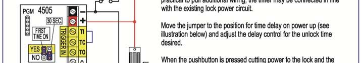
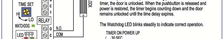
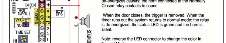
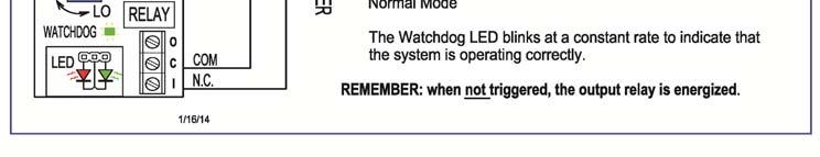
2 POWER INPUT (1) The 4505 requires VDC. The 4505 can be configured to trigger on power up. See Jumper Array (9) below. This feature is often used to add a timed unlock period to an existing lock when only power connections are available at the door. TRIGGER INPUT (2) The timer trigger can be either a normally closed or a normally open contact. An input is provided for both. To use a normally open contact, the normally closed trigger should be tied to common. Do not apply voltage to the trigger inputs, Use dry contacts only. The relay de-engergizes when a trigger is detected. The timing sequence begins when the trigger is removed. The 4505 is designed for Fail Safe operation. The relay is not energized when the timer is running. Fail secure operation is available as an option. OUTPUT ONE (3) There are two sets of DPDT relay contact sets available as timer outputs. Output One with a common, a normally closed and a normally open contact using standard terminal strip for connection is also available with a 3 pin header as an option. DPDT OUTPUT RELAY (4) The output relay contacts are rated for 2 Amps at 30 VDC. OUTPUT TWO (5) The second set of relay contacts (common normally closed and normally open) is available as a standard three-position terminal strip. LED OUTPUT (6) A powered output is available for direct connection to a bi-color LED (or a pair of discrete LEDs). The output changes state when the relay is energized. Most users connect a bi-color LED to the header such that RED is illuminated when the relay is not energized and GREEN is energized when the relay is energized. Since the center pin is common, to reverse the color order, merely rotate the orientation of the plug. WATCHDOG LED (7) The 4505 timer is controlled by a microprocessor. A watchdog circuit monitors the operation of the microprocessor and blinks at a steady rate (about 3 times per second) when the processor is operating correctly. This provides a continual visual indication that the system is operational. If the Watchdog Circuit stops blinking at a constant rate, contact Dortronics Technical Help. Always use transient voltage protection on the outputs when connecting an inductive load. Kickback (back EMF) from a coil can destroy relay contacts and may damage the electronics. Transient Voltage Suppression (TVS) diodes are available from Dortronics for $1.00 ea. Part # Connection of an inductive load without protection will void the warrantee. TIME DELAY ADJUST (8) The 4505 timer delay period can be adjusted from 1 to 60 seconds by means of a rotary control. Use a small screw driver to increase the delay time by turning the control clockwise or decrease the delay time by rotating the control counterclockwise. Longer time delays may be custom programmed at the factory for a small additional cost. Page 2 of 5 rev. 5/5/2017 DORTRONICS SYSTEMS. INC


3 JUMPERS FOR: 30 SECOND FIXED DELAY AND DELAY ON POWER-UP (9) DORTRONICS 7281 USER NOTES The 4505 timer delay period can be accurately set at thirty seconds by moving the top fixed delay jumper to the left two pins. See the diagram above. The 30 second delay has the accuracy of a computer and is not affected by barometric pressure or changes in the ambient temperature. For the timer to trigger on power up, move the lower jumper to the left two pins. This is a useful function for retrofitting a timed relock delay to existing door locks wired for power only with no control wiring available. When the power circuit is briefly interrupted (usually by a momentary pushbutton in series with the lock) the system goes immediately into the timer function as soon as the power is restored. This converts an existing momentary release switch into either a fixed 30 second door release or an adjustable release (from 1 to 60 seconds). PROGRAMMING PORT (10) The 4505 can be customized at the factory for non-standard applications. The time delay range can be easily increased by seconds, minutes or even hours for a small additional programming charge. Other custom features will be quoted on the basis of customer specifications. SPECIFICATIONS: POWER INPUT: TIMER RANGE: FIXED TIME: RELAY CONTACT RATING: SIZE: TRIGGER: OPERATION: TRIGGER HOLD OVER: VDC 1 60 SECONDS 30 SEC 2 30 VDC Max. 2 ¾ X 1 ½ Requires ¾ height clearance for connections Normally Open and Normally Closed Trigger Inputs Output Relay is NOT energized during Timer Function Relay is energized on trigger, timer countdown begins at trigger release TIMER SOLUTIONS: Page 3 of 5 rev. 5/5/2017 DORTRONICS SYSTEMS. INC

4 Page 4 of 5 rev. 5/5/2017 DORTRONICS SYSTEMS. INC
5 Product Warranties: 4500 Series Timers have a One Year Warranty against defects in material and workmanship. Defective units will be replaced or repaired based upon incoming evaluation and inspection. All other Dortronics components of the Electric Locking System shall be similarly warranted for a period of one year. Expressed warranties are conditionally based on the requirement that the items covered within the guarantee are used and maintained in accordance with the manufacturer's recommendations. A Return Authorization Number must be obtained and accompany all returns within 14 days of issue. Unused items returned for credit must be complete and packed in original unit box and are subject to a 15% restocking fee. Any shipping or order discrepancies must be reported within 5 days of receipt. Mike Palermo Sales/Customer Service Stuart Arthur Sales/Applications Specialist Bryan Sanderford - National Sales Manager] Joe Hanna Engineer/Applications Specialist Contact (Sales): Contact (Technical): Contact (Credit): Teri Harboy Accounting; New Customer Accounts Dortronics Systems Inc Fax Page 5 of 5 rev. 5/5/2017 DORTRONICS SYSTEMS. INC
J1939 POWERCELL Setup and Configuration Guide Universal Switch Interface
 Table of Contents J1939 POWERCELL Setup and Configuration Guide Universal Switch Interface Overview... 2 Warnings... 3 J1939 POWERCELL Technical Details... 4 POWERCELL Installation Steps... 5 Mounting
8. Do not install this product on the exterior of buildings. 9. Do not use as a doorstop. This will void warranty. Installation Instructions
 INSTALLATION 8310-IQ/8320-IQ IntelliMag Electromagnetic Locks Pre-Installation Instructions 1. This product must be installed according to all applicable building and life safety codes. 2. Due to the variety
1.0 Features and Description
 1.0 Features and Description The is an intelligent actuator designed for precise control of quarter turn valves and dampers. Using stepper motor technology, the SmartStep proportionally positions valves
DLKEK3HN INSTALLATION INSTRUCTIONS
 DLKEK3HN INDEX: INSTALLATION INSTRUCTIONS WIRING INSTRUCTIONS... PG 2-5 LED STATUS INDICATOR... PG 6 VALET/OVERRIDE BUTTON... PG 6 SHOCK SENSOR... PG 7 PROGRAMMABLE JUMPER-PINS... PG 7 PROGRAMMING REMOTE
INSTALLATION 8310/8320
 INSTALLATION 8310/8320 Electromagnetic Locks Pre-Installation Instructions 1. This product must be installed according to all applicable building and life safety codes. 2. Due to the variety of mounting
56- Electric Latch Retraction Exit Devices Installation and Wiring Instructions
 SECTION I: OVERVIEW 1. Description The Sargent 56- prefix ELR works with 80 Series exit devices to provide remote-controlled latch retraction. It is compatible with the following prefixes: 53 - Latchbolt
MST. Full Height Turnstiles. alvaradomfg.com
 Full Height Turnstiles alvaradomfg.com The is the most trusted, secure and reliable full height turnstile available. It is installed in thousands of locations around the world and offers key product features
Electrical Options Booklet. Table of Contents
 *24228413* 24228413 Electrical Options Booklet Table of Contents EL Wiring... EL Troubleshooting... SD/EL 98/99 Cylinder Dogging... SS Wiring... 330, 350, RX-330 and RX-350 Push Bar Trim Mechanical Installation...
Infinitybox Express Road Race Car Kit Installation Guide
 Table of Contents Infinitybox Express Road Race Car Kit Installation Guide Overview... 2 Warnings... 3 J1939 POWERCELL Technical Details... 4 IOX Input/Output Module Technical Details... 4 Kit Contents...
Installation Instructions Rotation Control Kit
 Installation Instructions Rotation Control Kit 45-101, REV. 11/14 1 TABLE OF CONTENTS SECTION 1 PURPOSE... 3 SECTION 2 INSTALLATION... 4 Test Installation...6 Disabling The System...6 Operation...6 2 45-101,
SALDET SALES & SERVICE, INC. CLINTON TOWNSHIP, MICHIGAN
 Form 1254 BRAKETRON Electronic Motor Brake Instructions SALDET SALES & SERVICE, INC. CLINTON TOWNSHIP, MICHIGAN TABLE OF CONTENTS SECTION TITLE PAGE I. Introduction 1 II. Specifications 1 III. Principles
BE SURE POWER IS DISCONNECTED PRIOR TO INSALLATION! FOLLOW NATIONAL, STATE, AND LOCAL CODES! READ THESE INSTRUCTIONS ENTIRELY BEFORE INSTALLATION!
 INSTALLATION INSTRUCTIONS FOR SYMCOM S MOTORSAVER MODEL 460 BE SURE POWER IS DISCONNECTED PRIOR TO INSALLATION! FOLLOW NATIONAL, STATE, AND LOCAL CODES! READ THESE INSTRUCTIONS ENTIRELY BEFORE INSTALLATION!
SECURITY DOOR CONTROLS
 CR4 FOUR STATION CONTROL MODULE The CR4 module operates on 12V or 24V DC and provides control of four (4) stations. Each CR4 station accepts a Dry () trigger input and provides one (1) Fused 2 Amp SPDT
TAILOR MADE METAL FABRICATIONS LTD. VEHICLE ACCESS CONTROL BARRIER (VAC B)
") TAILOR MADE METAL FABRICATIONS LTD. VEHICLE ACCESS CONTROL BARRIER (VAC B) TECHNICAL MANUAL v1.3 JANUARY 2014 Technical Manual (Updated 6 th January 2014) No Vehicle timer Vehicle delay timer Overrun timer
TAILOR MADE METAL FABRICATIONS LTD. VEHICLE ACCESS CONTROL BARRIER (VAC B) TECHNICAL MANUAL v1.3 JANUARY 2014 Technical Manual (Updated 6 th January 2014) No Vehicle timer Vehicle delay timer Overrun timer
User Manual. T6 Tachometer. Online: Telephone: P.O. Box St. Petersburg, Florida 33736
 User Manual T6 Tachometer Online: www.phareselectronics.com Telephone: 727-623-0894 P.O. Box 67251 St. Petersburg, Florida 33736 Table of Contents Overview... 1 Description... 1 Wiring... 1 T6 Tachometer
Setup and Configuration Guide Universal Switch Interface
 Table of Contents J1939 inmotion Cell Setup and Configuration Guide Universal Switch Interface Overview... 2 Warnings... 3 J1939 inmotion Cell Technical Details... 4 inmotion Cell Installation Steps...
SmartLock Fifth Wheel
 SmartLock Fifth Wheel ISO/TS16949 REGISTERED ISO/TS16949 TB-004 REGISTERED August 2013 TB-042 REV.1 This technical bulletin is intended to provide information on the operation and troubleshooting of Fontaine
8. Do not install this product on the exterior of buildings. 9. Do not use as a doorstop. This will void warranty. Installation Instructions
 INSTALLATI DE8310 Delayed Egress Electromagnetic Locks Pre-Installation Instructions 1. This product must be installed according to all applicable building and life safety codes. All installations must
PRODUCT INFORMATION BULLETIN
 724-283-4681 724-283-5939 (fax) PRODUCT INFORMATION BULLETIN DESCRIPTION The, Model 10-7100 is one in a series of critical speed switches that monitor speed and detect motion in all types of machinery
AUTO ISOLATOR I AN AUTOMATIC LOSSLESS BATTERY ISOLATOR FOR DUAL BATTERY SYSTEMS
 INSTRUCTION MANUAL AUTO ISOLATOR I AN AUTOMATIC LOSSLESS ISOLATOR FOR DUAL SYSTEMS MODEL #: 091-139-2-12 VOLTAGE: 12 VDC OUTPUT: 12 VOLTS, 3 AMPS PARALLELING : 200 AMPS File: IM-091-139-2-12 Rev: revc
MST. model. alvaradomfg.com
 alvaradomfg.com FULL HEIGHT TURNSTILES model The is the most trusted, secure and reliable full height turnstile available. It is installed in thousands of locations around the world and offers key product
canfield connector 8510 Foxwood Court Youngstown, Ohio (330) Fax: (330)
 Fax: (330)") canfield connector 8510 Foxwood Court Youngstown, Ohio 44514 (330) 758-8299 Fax: (330) 758-8912 www.canfieldconnector.com MODEL MBT MULTIFUNCTION BLOCK TIMER 12 FUNCTIONS IN 1 TIMER General Description
canfield connector 8510 Foxwood Court Youngstown, Ohio 44514 (330) 758-8299 Fax: (330) 758-8912 www.canfieldconnector.com MODEL MBT MULTIFUNCTION BLOCK TIMER 12 FUNCTIONS IN 1 TIMER General Description
Wiring Installation Instructions for : Pressure. Wiring Installation Instructions for : Temperature. 2 1/16 Spek Pro Professional Racing Gauge
 Wiring Installation Instructions for : Pressure DIAGRAM 1 Pressure Sensor 1/8 NPT 3 AMP Wiring Installation Instructions for : Temperature GAUGE 12-Pin Wiring Harness & Plug Firewall Grommet DIAGRAM 2
Micro Autonomations LLC
 Description Micro Autonomations LLC www.ma-embedded.com Mercedes Fan Controller V2.1 This module controls C-Class fans from Mercedes. It has three different methods to control the fan. It will vary the
Operations Manual. Zero Speed Switch Sensor Model ZS09P
 Zero Speed Switch Sensor Model ZS09P The must be referred to for correct installation. Failure to comply with the shall void all warranties and liabilities. Overview The Phares Electronics Model ZS09P
GENSET CONTROL MODULE A121A / A241A
 Technical Data Sheet GENSET CONTROL MODULE A121A / A241A Features: Models for both 12V and 24V systems. One model for both spark ignition and diesel engines. 4-alarm light outputs with lamp-test provisions.
LP-2500/2600. Installation and Setup Guide. Lighting Control Panels. Revision 3.1 July 1999
 /2600 Lighting Control Panels Installation and Setup Guide Revision 3. July 999 Phone:770-429-3043 http://www.triateklighting.com sales@triateklighting.com Installation Guide /2600 Lighting Panels Table
Installation Instructions
 I N S T A L L A T I O N 8310/8320 8330/8340 Electromagnetic Locks Pre-Installation Instructions 1. This product must be installed according to all applicable building and life safety codes. 2. Due to the
TCM D Single Zone, 24 Volt DC Timer Control Module User s Manual D-M-E Company
 TCM-03-024D Single Zone, 24 Volt DC Timer Control Module User s Manual D-M-E Company D-M-E Company TCM-03-024D Page 1 SAFETY D-M-E Company products have been designed to be safe and simple to operate.
APOLLO Gate Operators, Inc.
 APOLLO Gate Operators, Inc. Model BA12 12 VOLT DC BARRIER ARM OPERATOR INSTALLATION MANUAL 0707 CONTENTS IMPORTANT SAFETY INSTRUCTIONS... 3 Applications... 4 Pre-Installation Checklist... 5 Operator Installation...
Installation, Operation and Maintenance Manual
 Document 47681 Vari-Green Motor and Controls Installation, Operation and Maintenance Manual Please read and save these instructions for future reference. Read carefully before attempting to assemble, install,
SHORT-STOP. Electronic Motor Brake Type G. Instructions and Setup Manual
 Electronic Motor Brake Type G Instructions and Setup Manual Table of Contents Table of Contents Electronic Motor Brake Type G... 1 1. INTRODUCTION... 2 2. DESCRIPTION AND APPLICATIONS... 2 3. SAFETY NOTES...
Note: Read this manual carefully before installing the operator and place this installation manual in an accessible place near the operator.
 Installation & Instruction Manual Electronic Control Board (ECB) Note: Read this manual carefully before installing the operator and place this installation manual in an accessible place near the operator.
Models CHASSIS LUBE ELECTRIC GREASE PUMP Series "C" - 13C MAY FORM Page. Section - Q3
 Models 94422 CHASSIS LUBE ELECTRIC GREASE PUMP Series "C" MAY - 2004 FORM 403467 Section - Q3 Page - 13C 9.00" (229 mm) 13.75" (350 mm) 0.35" (9mm) Mounting Holes 4.76" (121 mm) 9.84" (250 mm) Do not use
International & MB45/55 w/allison 2000 and Shift Lock Solenoid
 Intelligent Lift Interlock System (ILIS701-D) - Installation Instructions International & MB45/55 w/allison 2000 and Shift Lock Solenoid To aid in installation, first gain access to the connection points.
Model CHASSIS LUBE ELECTRIC GREASE PUMP Series "C"
 Model 94222 CHASSIS LUBE ELECTRIC GREASE PUMP Series "C" Indicates change MAY - 2004 FORM 403466 Section - Q3 Page - 12B 7.75" (197 mm) 12.6" (321 mm) 0.35" (9 mm) Mounting Holes 4.85" (123 mm) 8.85" (225
Models CHASSIS LUBE ELECTRIC GREASE PUMP Series "C" - Q3. MAY FORM Section
 Models 94822 CHASSIS LUBE ELECTRIC GREASE PUMP Series "C" - Q3 MAY - 2004 FORM 403468 Section Page - 14B 13.00" (330 mm) 17.72" (450 mm).35" (9 mm) Mounting Holes 4.72" (120 mm) 9.84" (250 mm) Figure 1
SE-3SCR-LM MANUAL MOTOR LOAD MANAGER
 3714 Kinnear Place Saskatoon, SK Canada S7P 0A6 Ph: (306) 373-5505 Fx: (306) 374-2245 www.littelfuse.com/relayscontrols SE-3SCR-LM MANUAL MOTOR LOAD MANAGER MARCH 5, 2013 REVISION 4 MOTOR LOAD MANAGER
HANDLING MECHANICAL INSTALLATION
 2 INSTALLATION DESCRIPTION The and 2 Delay Egress Systems are 1500 pound holding force (holding force not evaluated by UL) per leaf electromagnetic locks, electronically controlled to provide a 15 or 30
GENSET CONTROL MODULE LEVEL 1 A121CM / A241CM. Special logic to re-establish cranking following a false start.
 Technical Data Sheet GENSET CONTROL MODULE LEVEL 1 A121CM / A241CM Features: Models for both 12V and 24V systems. One model for both spark ignition and diesel engines. 5-alarm light outputs with lamp-test
Motorized Electric Latch Retraction
 ; SECTION I: OVERVIEW 1. Description The Corbin Russwin MELR Electric Latch Retraction (ELR), refer to Figure 1, works with ED4000 & ED5000 Series exit devices to provide remote-controlled latch retraction
ILISC515-A Shift Interlock (Manual Lift Door) Ford Transit
 Ford Transit") An ISO 9001:2008 Registered Company ILISC515-A Shift Interlock (Manual Lift Door) 2015-2018 Ford Transit Introduction The ILISC515-A is a microprocessor driven system for controlling wheelchair lift operation.
An ISO 9001:2008 Registered Company ILISC515-A Shift Interlock (Manual Lift Door) 2015-2018 Ford Transit Introduction The ILISC515-A is a microprocessor driven system for controlling wheelchair lift operation.
Irrigation Components International, Inc.
 1500 Irrigation Components International, Inc. P.O. Box 945 Daphne, AL 36526 USA Tel: 251.626.5470 Fax: 251.447.0190 Email: icii@irricomp.com Visit us on the web: www.irricomp.com 1500 TABLE OF CONTENTS
IMI vibration switch USER MANUAL INSTALLATION - OPERATION - MAINTENANCE
 USER MANUAL IMI vibration switch INSTALLATION - OPERATION - MAINTENANCE Z0929039_A ISSUED 03/2017 READ AND UNDERSTAND THIS MANUAL PRIOR TO OPERATING OR SERVICING THIS PRODUCT. contents Overview General
HYPPOETL HYPPO DUALETL 12 VOLT DC Swing Gate Operator
 HYPPOETL HYPPO DUALETL 12 VOLT DC Swing Gate Operator Manufactured by NICE SpA INSTALLATION MANUAL 08/10 CONTENTS IMPORTANT SAFETY INSTRUCTIONS... 3 Applications...... 4 Pre-Installation Checklist... 5
Customer Education. HGS System operatons Description. 50-Amp Transfer Switch (Selected Circuits)
") Customer Education HGS System operatons Description 50-Amp Transfer Switch (Selected Circuits) 20-seconds Engine Warm-up, Transfer to Generator power (Power only to selected circuits on transfer switch
Customer Education HGS System operatons Description 50-Amp Transfer Switch (Selected Circuits) 20-seconds Engine Warm-up, Transfer to Generator power (Power only to selected circuits on transfer switch
ACSI MODEL 1440 POWER SUPPLY INSTALLATION INSTRUCTIONS
 II 1400-8 Features: ACSI MODEL 1440 POWER SUPPLY INSTALLATION INSTRUCTIONS Filtered/Regulated 24 Volts DC Up to Full 2 Amps Load Capacity Class 2 Rated Outputs Overload, Over Voltage, and Short Circuit
MST FULL HEIGHT TURNSTILES TYPICAL INSTALLATION SITES COMMON APPLICATIONS DESCRIPTIVE SPECIFICATIONS ALVARADOMFG.COM
 DESCRIPTIVE SPECIFICATIONS The is the most trusted, secure and reliable full height turnstile available. It is installed in thousands of locations around the world and offers key product features and benefits
94 Series - Socket overview for 55 series relays
 94 Series - Socket overview for 55 series relays 94.04 See page 7 Module Socket Relay Description Mounting 99.02 94.02 55.32 Screw terminal (Box clamp) socket Panel or 35 mm rail - Coil indication and
INTERNATIONAL 3200 AND Freightliner MB
 An ISO 9001:2000 Registered Company INTERNATIONAL 3200 AND Freightliner MB55 2002-2008 Intelligent Lift Interlock System (ILIS701-D) - Installation Instructions International & MB45/55 w/allison 2000 and
Installation, Operating and Maintenance Manual
 DOCUMENT # BASTD1007 Installation, Operating and Maintenance Manual 1. Technical Note - Hopper Hammer Initial Settings Pages 7 and 8 of the Hopper Hammer Models PASTD583-2 & PASTD978 Installation, Operating
MANUAL Model: PT 12/24-60 Solar Converters Inc. - Rev. F
 1.0 Specification MANUAL Model: PT 12/24-60 Solar Converters Inc. - Rev. F Note: This unit is a Multi - Voltage unit with adjustable input panel and output battery adjustment. Please review the section
IMPORTANT SAFEGUARDS READ THIS MANUAL AND FOLLOW ALL SAFETY INSTRUCTIONS THOROUGHLY BEFORE OPERATING THE EMIU INVERTER SYSTEM SAVE THESE INSTRUCTIONS
 THIS UNIT CONTAINS A RECHARGEABLE VALVE-REGULATED LEAD ACID BATTERY. PLEASE RECYCLE OR DISPOSE OF PROPERLY. IMPORTANT SAFEGUARDS INTERRUPTIBLE EMERGENCY LIGHTING UNIT INVERTER INSTRUCTION MANUAL When using
GENSET CONTROL MODULE LEVEL 0 A120A. User selectable time delays for engine start and engine stop (cool down).
.") Technical Data Sheet GENSET CONTROL MODULE LEVEL 0 A120A Features: One model for both spark ignition and diesel engines. 4-alarm light outputs with automatic lamp-test provision. Overspeed adjustment not
Technical Data Sheet GENSET CONTROL MODULE LEVEL 0 A120A Features: One model for both spark ignition and diesel engines. 4-alarm light outputs with automatic lamp-test provision. Overspeed adjustment not
Door Control Panel TS 960. instructions. (Design and functions subject to change) /
 /") Electrical operating Operating instructions Door Control Panel TS 960 GB (Design and functions subject to change) 51171098 / 10.2002 OPERATING INSTRUCTIONS PAGE SAFETY DIRECTIONS...4 FUNCTION OVERVIEW...6
Electrical operating Operating instructions Door Control Panel TS 960 GB (Design and functions subject to change) 51171098 / 10.2002 OPERATING INSTRUCTIONS PAGE SAFETY DIRECTIONS...4 FUNCTION OVERVIEW...6
Pivot Point Lite Wiring Manual
 2009-10 Pivot Point Lite Wiring Manual (small square single circuit board design) Section 1 Pages 2-3 Pivot wiring to monitor and/or stop the irrigation system. Section 2 Page 4 Section 3 Page 4 Simple
GENERATOR START CONTROL MODULE
 GENERATOR START CONTROL MODULE Operating and Installation Instructions Many automatic control features: Automatic starting, load transfer & shutdown of gas/diesel generators, especially for off-grid uses
MR16out Processor Installation and Specifications
 MR16out Processor Installation and Specifications 1. General: www.mercury-security.com 2355 MIRA MAR AVE., LONG BEAH, A 90815-1755, (562) 986-9105 FAX (562) 986-9205 This device complies with part 15 of
IMPORTANT SAFEGUARDS READ THIS MANUAL AND FOLLOW ALL SAFETY INSTRUCTIONS THOROUGHLY BEFORE OPERATING THE LMIU INVERTER SYSTEM SAVE THESE INSTRUCTIONS
 THIS UNIT CONTAINS A RECHARGEABLE VALVE-REGULATED LEAD ACID BATTERY. PLEASE RECYCLE OR DISPOSE OF PROPERLY. IMPORTANT SAFEGUARDS INTERRUPTIBLE EMERGENCY LIGHTING UNIT INVERTER INSTRUCTION MANUAL When using
ASSA ABLOY. Installation Instructions. MP9800 Series Multi-Point Lock with MELR Option (Electric Latch Retraction)
") Installation Instructions MP9800 Series Multi-Point Lock MP9800 Series Multi-Point Lock, the global leader in door opening solutions 1 of 20 Copyright 2016 Corbin Russwin Inc., an Group company. Table
Installation Instructions MP9800 Series Multi-Point Lock MP9800 Series Multi-Point Lock, the global leader in door opening solutions 1 of 20 Copyright 2016 Corbin Russwin Inc., an Group company. Table
BZ-150. Installation Instructions. Power Pack SPECIFICATIONS
 SPECIFICATIS Voltages...120/. 50/60Hz Load Requirements Ballast... 20amp @120/ Incandescent... 20amp @ Motor... 1HP @120/240VAC Output...225mA @ (with relay connected) Input Control... 12- Hold... 12-
MD10. Engine Controller. Installation and User Manual for the MD10 Engine Controller. Full Version
 MD10 Engine Controller Installation and User Manual for the MD10 Engine Controller. Full Version File: MartinMD10rev1.4.doc May 16, 2002 2 READ MANUAL BEFORE INSTALLING UNIT Receipt of shipment and warranty
GLM SERIES CONTROL Users Manual Rev:
 GLM SERIES CONTROL Users Manual Rev: 808062 Connecting Power Page 2 Motor Terminal Wiring Diagrams Page 3 Getting Started / Setup Page 4 1. Obstruction Detection Devices Page 4 2. Checking Power and Direction
Pre-Installation Instructions
 Pre-Installation Instructions 1. This product must be installed according to all applicable building and life safety codes. All installations must be approved by the Authority Having Jurisdiction (AHJ).
Owner s Guide PROCOMP
 professional series Owner s Guide PROCOMP Deluxe Vehicle Security and Remote Start System with 900 Mhz 2 Way Confirming OLED Remote Control IMPORTANT NOTE: The operation of the Security and Convenience
THE 4481 ADJUSTABLE TIMED OUTPUT MACHINE CONTROL
 Anti-Tiedown Control THE 4481 ADJUTABLE TIMED UTPUT MACHINE CNTRL The 4481 control has all the anti-tiedown switch monitor features of the 4480 control with the added feature of a knob adjustable timed
Subject: Models/Years Affected: Origination Date: Revision Date:
 Subject: Models/Years Affected: Origination Date: Revision Date: UI Bulletin #124f Intermittent Cluster, Radio and HVAC Display Resets on Snow Plow Trucks 2014 Chevrolet Silverado 1500 2015-2017 Chevrolet
GENSET CONTROL MODULE A121H / A241H. User selectable time delays for engine start and engine stop (cool down).
.") Technical Data Sheet GENSET CONTROL MODULE A121H / A241H Features: Models for both 12V and 24V systems. One model for both spark ignition and diesel engines. 4-alarm light outputs with lamp-test provisions.
Technical Data Sheet GENSET CONTROL MODULE A121H / A241H Features: Models for both 12V and 24V systems. One model for both spark ignition and diesel engines. 4-alarm light outputs with lamp-test provisions.
EDC-E. Waist HIGH Turnstiles. alvaradomfg.com
 Waist HIGH Turnstiles alvaradomfg.com Descriptive SPECIFICATIONS The is an extended length cabinet turnstile with extended length turnstile arms. It is a rugged, multi-purpose turnstile used to provide
INSTRUCTION MANUAL. A battery protector for vehicles with equipment that Is operated with the engine not running. MODEL# INPUT: 12 Volts D.C.
 INSTRUCTION MANUAL FILE: IM_091-141_Rev_B DATE: 10-02-03 LOAD MANAGER P A battery protector for vehicles with equipment that Is operated with the engine not running MODEL# 091-141 INPUT: 12 Volts D.C.
INSTALLATION MANUAL. Model: PLUS For Technical Assistance, please call (800) , or visit
 , or visit") R Vehicle Security INSTALLATION MANUAL Model: PLUS-4700 This device complies with part 15 of the FCC rules. Operation is subject to the following two conditions: (1) This device may not cause harmful interference;
R Vehicle Security INSTALLATION MANUAL Model: PLUS-4700 This device complies with part 15 of the FCC rules. Operation is subject to the following two conditions: (1) This device may not cause harmful interference;
MDCSL V, 30A
 MDCSL100-050301 50V, 30A Sensorless Controller User s Guide A N A H E I M 4985 E. Landon Drive, Anaheim, CA 92807 e-mail: info@anaheimautomation.com A U T O M A T I O N (714) 992-6990 fax: (714) 992-0471
GENERATOR START CONTROL MODULE
 GENERATOR START CONTROL MODULE Operating and Installation Instructions Many automatic control features: Automatic starting, load transfer & shutdown of gas/diesel generators, especially for off-grid uses
Model HEA Multicontact Auxiliary
 GE Grid Solutions Model HEA Multicontact Auxiliary Features and Benefits Electrically separate outputs available Various shaft lengths available Locks equipment out of service Applications Contact multiplication
INSTALLATION INSTRUCTIONS
 INSTALLATION INSTRUCTIONS TEC20 TEC20H ELECTRONIC CONTROLLER BARD MANUFACTURING COMPANY Bryan, Ohio 43506 Since 1914...Moving ahead, just as planned. Manual: 2100-306D Supersedes: 2100-306C File: Volume
2 & 3 Door Siphon Installation Instructions
 & Door Siphon Installation Instructions Door Siphon System System Facilities Only one door to be released electrically at any one time. A door controller at each door (up to eight doors) to facilitate
Installation, Operation, and Maintenance Manual. Automatic Fire Damper
 Installation, Operation, and Maintenance Manual Automatic Fire Damper Part # 458295 Designed to close in fire situations. Reset by activating the reset switch. UL Listed Constructed in Accordance with
Installation, Operation and Maintenance Manual
 Document 473681 Vari-Green Motor and Controls Installation, Operation and Maintenance Manual Please read and save these instructions for future reference. Read carefully before attempting to assemble,
SM361 RIG SWITCH CONSTRUCTION MANUAL
 SM361 RIG SWITCH CONSTRUCTION MANUAL Document ver 1, For software release ver 1.1 May 27, 2016 Controls the power of 12V equipment while a vehicle is in use Product Development by: SM361 RIG SWITCH OVERVIEW
Installation and Operation Manual. LD LED Dimmer
 Installation and Operation Manual LD12-002 LED Dimmer SM85 ISSUE 1.00 Northern Airborne Technology Ltd. 1925 Kirschner Road Kelowna, BC, Canada. V1Y 4N7 Telephone (250) 763-2232 Facsimile (250) 762-3374
Total solder points: 126 Difficulty level: beginner advanced POWER DIMMER 230V) K8038 ILLUSTRATED ASSEMBLY MANUAL
 K8038 ILLUSTRATED ASSEMBLY MANUAL") Total solder points: 126 Difficulty level: beginner 1 2 3 4 5 advanced POWER DIMMER (1KW @ 230V) K8038 NOISE SUPPRESSED ACCORDING TO EN55015 Class microcontroller high power dimmer with non volatile memory
Total solder points: 126 Difficulty level: beginner 1 2 3 4 5 advanced POWER DIMMER (1KW @ 230V) K8038 NOISE SUPPRESSED ACCORDING TO EN55015 Class microcontroller high power dimmer with non volatile memory
MODEL RMS INSTALLATION INSTRUCTIONS. CONTENTS Page A. Introduction 1. Usage 2 2. How it operates 2
 CONVEYOR COMPONENTS COMPANY Division of Material Control, Inc. 130 Seltzer Road, PO Box 167 Croswell, MI 48422 USA PHONE: (810) 679-4211 TOLL FREE (800) 233-3233 FAX: (810) 679-4510 Email: info@conveyorcomponents.com
Generator Start Control Module
 Generator Start Control Module Part# GSCM Rev C. Code Version: 5.13 ATKINSON ELECTRONICS, INC. 14 West Vine Street Murray, Utah 84107 Table of Contents Operations... 3 Specifications... 3 GSCM Wiring Diagram...
Model Railway Reverse Loops How to automate reversing tracks on your two-rail layout, whether DC, DCC or AC powered
 Model Railway Reverse Loops How to automate reversing tracks on your two-rail layout, whether DC, DCC or AC powered Because of the way power is supplied to electric model trains, two-rail layouts require
ELECTRIC FENCE ENERGIZER SERVICE MANUAL MODEL 950 SERVICE MANUAL FOR OLLI 950 FENCE ENERGIZERS
 ELECTRIC FENCE ENERGIZER MODEL 950 SERVICE MANUAL Service Manual for OLLI 950 Page 1/16 Date 20.10.2014 Table of Contents...1 1. IMPORTANT SAFETY INSTRUCTIONS...2 2. SPECIFICATIONS...3 3. CONSTRUCTION...4
USER S MANUAL GPC SERIES LOW VOLTAGE DISCONNECT. Galley Power LLC.
 USER S MANUAL GPC SERIES LOW VOLTAGE DISCONNECT Galley Power LLC www.galleypower.com Table of Contents Safety Notice... 3 Disclaimer... 3 Safety Instructions... 4 1. Introduction... 5 1.1 Features and
MODEL 422 Submersible Pump Controller
 MODEL 422 Submersible Pump Controller Monitors True Motor Power (volts x current x power factor) Detects Motor Overload or Underload Operates on 120 or 240VAC, Single-phase or 3-phase Built-in Trip and
ALVARADO (1029 mm) 25 (635 mm) 36.5 (927.1 mm)
 25 (635 mm) 36.5 (927.1 mm)") ALVARADO EDCX Bullnose Waist High Turnstile Technical Specifications Dimensions Unit Height: Unit Width: Unit Depth: 40.5 (1029 mm) 25 (635 mm) 36.5 (927.1 mm) Materials Cabinet: Formed and welded 14 gauge
ALVARADO EDCX Bullnose Waist High Turnstile Technical Specifications Dimensions Unit Height: Unit Width: Unit Depth: 40.5 (1029 mm) 25 (635 mm) 36.5 (927.1 mm) Materials Cabinet: Formed and welded 14 gauge
Generator Start Control Module
 Generator Start Control Module Part# GSCM-mini-i ATKINSON ELECTRONICS, INC. 14 West Vine Street Murray, Utah 84107 Contact cbdsales@atkinsonel.com for the proper hookup diagram. Please include the generator
CALTRAP INSTALLATION AND OPERATIONS MANUAL
 INSTALLATION AND OPERATIONS MANUAL NOTE Please read this entire installation and operations manual before energizing the. Safety Considerations: Installing and servicing capacitor equipment can be hazardous.
Installation, Operation and Maintenance Manual
 Document 473681 Vari-Green Motor and Controls Installation, Operation and Maintenance Manual Please read and save these instructions for future reference. Read carefully before attempting to assemble,
MODEL HSC-24 AUTOMATIC SNOW/ICE MELTING SYSTEM CONTROL PANEL
 MODEL HSC-24 AUTOMATIC SNOW/ICE MELTING SYSTEM CONTROL PANEL DESCRIPTION The Snow Switch Model HSC-24, 24-volt Pavement-Mounted Snow and Ice Sensor reliably detects snow and ice conditions on pavement
LCN AUTOMATIC OPERATORS
 LCN AUTOMATIC OPERATORS SENIOR 9530 SENIOR 9540 SENIOR 9550 SENIOR 9560 8310 ACCESSORIES LCN ELECTROMECHANICAL POWERED SYSTEMS ELECTROMECHANICAL AUTOMATIC OPERATORS LCN s electromechanical products are
RR Concepts. The StationMaster can control DC trains or DCC equipped trains set to linear mode.
 Jan, 0 S RR Concepts M tation aster - 5 Train Controller - V software This manual contains detailed hookup and programming instructions for the StationMaster train controller available in a AMP or 0AMP
Electro Wizard Battery Disconnect Switch
 TM Electro Wizard Battery Disconnect Switch FR1051 Mounting Diagram Positive disconnection, 12V GROUNDED SOLENOID (power supply coil negative) FR1051 Technical Specifications Positive disconnection, 12V
Transfer switch GTEC open or delayed transition
 Transfer switch GTEC open or delayed transition 40-1250 Amp Description The GTEC automatic transfer switch combines reliability and flexibility in a small, economical package for transferring loads between
MDC V, 30A Brushless Controller. User s Guide L East Orangefair Lane, Anaheim, CA
 MDC150-012301 12V, 30A Brushless Controller User s Guide A N A H E I M A U T O M A T I O N 910 East Orangefair Lane, Anaheim, CA 92801 e-mail: info@anaheimautomation.com (714) 992-6990 fax: (714) 992-0471
MODEL 520 REMOTE START ENGINE MANAGEMENT SYSTEM
 MODEL 520 REMOTE START ENGINE MANAGEMENT SYSTEM DSE 520 ISSUE 4 4/4/02 MR 1 TABLE OF CONTENTS Section Page INTRODUCTION... 4 CLARIFICATION OF NOTATION USED WITHIN THIS PUBLICATION.... 4 1. OPERATION...
Digital Trim. Part # 1037 WARRANTY AND DISCLAIMER
 2036 Fillmore Street Davenport, Ia. 52804 563-324-1046 www.racedigitaldelay.com Digital Trim Part # 1037 WARRANTY AND DISCLAIMER DIGITAL DELAY ELECTRONICS INC. WARRANTS THE PRODUCTS IT MANUFACTURES AGAINST
ca 5550SST Owner s Guide
 PROFESSIONAL SERIES ca 5550SST Owner s Guide Deluxe Vehicle Remote Start System with 900Mhz 2 Way Confirming LCD Remote Control IMPORTANT NOTE: The operation of the Security and Convenience System as described