Design and Analysis of Heat Exchanger
|
|
|
- Aubrey Woods
- 6 years ago
- Views:
Transcription


1 ) Design and Analysis of Heat Exchanger 2012 Design and Analysis of Heat Exchanger Crompton Greaves Ltd. Large and Traction Machine Division D-5, Ind. Area MPAKVN, Mandideep MP Ph: Website: AKASH BEHL & YASH RANE Indian Institute of Technology Roorkee
2 2 BONAFIDE CERTIFICATE This is to certify that the project report on Design and Analysis of Heat Exchanger is the bona fide work of Akash Behl and Yash Rane, students from Indian Institute of Technology Roorkee, who carried out the project work under my supervision during the summer internship Mr. Parag Bhandarkar Senior Manager R&D Division Crompton Greaves Ltd. Large and Traction Machines Division Mandideep
3 3 Table of Content Preface 4 Acknowledgement 5 Project Outline 6 Operational Flowchart 7 Chapter 1: Designing and Analysis of Project 8 Results 13 Chapter 2: Study of Heat Exchangers 16 - Header Plate Selection 17 - Basics of Heat Exchanger 18 - Baffle Selection 22 - Tube Selection 24 - Fin Selection 27 - Fan Discharge 30 Appendix 1: BWG 32 Appendix 2 : Air Properties 34
4 4 PREFACE Heat Exchangers play a very crucial role when it comes to transference of heat energy between fluids. Its versatility and diversified applications makes it popular in process industries, conventional and nuclear power stations, steam generators, alternative energy applications including ocean, thermal and geothermal. The classification of heat exchangers is mainly done on the type of fluids that are involved in transference of energy. This project report is a detailed compendium of the factors that has to be considered during designing of a shell and tube heat exchanger. Starting with the basics of heat exchanger, this report covers Selection of Tube; its material; its surface area; its length, fin configuration, baffle configuration and their orientation, fan laws and discharge characteristic etc. All the above factors are covered separately in different section. Each section details a systematic approach that must be followed depending on the boundary conditions.
5 5 ACKNOWLEDGEMENT With sheer delight and immense satisfaction, I would like to take this opportunity to convey my gratitude towards all the people who were responsible in making this project a memorable experience. My foremost thanks to Mr. Parag Bhandarkar, Senior Manager R&D Division, for his support and guidance without whom this project could never have taken off. We would also like to thank Mr. Prashant Sharma, Executive Design Engineer, for his innovative thinking and unconventional strategies that helped me during the entire project.
6 6 PROJECT OUTLINE The ultimate aim of this report is to design an Air Cooled Heat Exchanger, preferably of shell and tube type, that can be used to transfer the heat energy generated in the windings of 3-phase Induction motor working at 800 rpm (Assumed). Following figure details the boundary conditions for the heat exchanger. Specifications: Air Flow Rate from External Fan (Cold Fluid) = 30 m 3 /s Inlet temperature of cold fluid (external fan) = 45 o C External temperature of cold fluid (external fan) = 61 o C Inlet Temperature of Hot Fluid (Internal Fan) = 84 o C Outlet temperature of Hot Fluid (Internal Fan) = 64 o C Heat Exchange Capacity = 500 KW Dimensions of Heat Exchanger = 2400 x 2250 x 3900 (in mm) Selection of factors Material of Tubes and its cost consideration Pattern of Tubes Air Flow rate from Internal Fan Fin Selection on surface Flow of Fluid (cross, parallel and counter) Factor of Fouling and Corrosiveness Assumptions: Specific Heat Capacity air is assumed to be constant for temperature difference of 20 o C Velocity of air does not change in the different region as mentioned in diagram.

7 7 Operational Flowchart Step 1 Selection of standard HE tube dimension Step 2 Calculation of Reynolds no. for 6 regions. Step 3 Step 4 Step 5 Calculation of Nusslet No. in each region Calculate Convection Heat Transfer Coefficient for each region Calculate Total Resistance, heat capacity rate and hence total no. of transfer units (NTU) Step 6 Evaluate Effectiveness, Q(maximum) and hence Q(actual) Step 7 Depict outlet temperatures of hot and cold fluid Step 8 Selection of standard Fin specifications Step 9 Calculate Fin surface area and ξ Step 10 Using Proper graph for fin profile calcuate efficieny Step 11 Calculate total area of fin and hence calculate total heat dissipated
8 8 Chapter 1 Designing and Analysis of Project Step 1: Slection of Tube Dimensions, Material, Configuration In heat exchanger we use standardized tube dimension that is clearly depicted in Appendix 1. This table is a description of tubes based on their BWG parameter and gives Inner Diameter, External surface area, internal surface area, flow area etc. For the first iteration we have selected the outer diameter as 1.5 inch and thickness as.065 inch (BWG 16). Using this data, we calculate inner diameter, internal and external surface area per unit length, inner and outer cross section area. As we get this data i t is easy to calculate transverse and longitudinal pitch. Optimally transverse pitch (S t ) to outer diameter (OD) ratio is We assumed it to be 1.5 for first iteration. As mentioned in the Chapter 2 of this report, for maximum efficiency, staggered configuration is preferred (60 o ). So clearly, S t = S d and S l = 1.732*S t /2 We have considered 2.4x2.05x3.7 (in m) as the total region for piping because the complete volume cannot be used for piping. So total no pipes can be calculated be determining no. of columns (N c ) and no. of tubes in each column(n tc ). Hence total no. of pipes are N c X N tc. For deciding the baffle cut, it can range from 20% - 49%. We assumed it to be 25% for first iteration. Once baffle cut is determined, we can calculate no. of tubes in cross flow and parallel/counter flow region by assuming the piping density to be constant. So total no. of pipes in Cross Flow = 0.75* Total no. of pipes (N t ) And total no. of pipes in Parallel/ Counter Flow = 0.25 * Total No. of Pipes (N t ) Step 2: Calculation of Reynolds no. for 6 regions To calculate Reynolds no. inside and outside the tubes we need to calculate mass flow V maximum on both the sides. For inside the tube: 1. Total volume flow rate is given. We divide it by total no. of tubes to determine the volume flow rate in each tube.
9 9 2. Using Q = A x V. We know Q in each pipe and Flow area of air inside the pipe and hence we calculate V max. 3. For inside the tube, Critical length is inner diameter and kinematic viscosity is know. So by using the following relation, we can calculate Reynolds No. Reynolds No. = Critical Length * V (max.) / Kinematic Viscosity For calculation of Reynolds No. outside the tube: 1. We know the volume flow rate of the internal fan. So again using the Q = A x V. We can calculate the V max. Here the area is assumed to be consist of 1/6 rd length of total length of Heat Exchanger i.e. 0.4m. So total area is 0.4m * 2.25m. 2. Once we have the V max. We can again use the aforementioned relation of Reynolds no., but the critical length will be outside diameter of the tube. Reynolds No. will be same for inside the tube flow but it will change in case of the shell flow because the flow area in each region Is different that will change the Vmax. and hence the Reynolds No. and Nusselt No. Step 3: Calculation of Nusselt No. Nusselt no. calculations are totally different for the air flow inside and outside the HE tubes. It also depends on the laminar or turbulent flow of the air. Let s discuss each of the air flow separately: Inside the tube: 1. Laminar Flow: For the fully developed laminar flow inside the tube, the Nusselt no. is constant. For isothermal surface, it is 3.66 and for constant heat flux condition, it is Turbulent Flow: The flow in pipes is fully turbulent for Re 10,000. Turbulent flow is commonly utilized in practice because of the higher heat transfer coefficients associated with it. To calculate the Nusselt no. is case of turbulent flow, we use Gnielinski (1976) equation. F is Darcy s friction factor given as, Now, while calculating Nusselt no. outside the tube i.e. in the shell, we have to consider three different flow viz. Cross Flow, Parallel Flow and Counter Flow. Let s study their relation one-by-one: Outside the tube: Cross Flow: When the hot air will flow from the tube bank, Nusselt no. mainly depends on the transverse and longitudinal pitch, Reynolds. No. and Prandtl no. Following table is the Nusselt no. expression for cross flow over tube banks for N>16 and 0.7<Pr<500
 ^0.6 * (Pr)^0.33 Step 4: Calculation of Convection Heat transfer coefficient (h) After calculating Nusselt no.")
10 10 Parallel Flow / Counter Flow: For the parallel flow, we have to consider the fact, whether the flow is laminar or turbulent. Nusselt no. is case of parallel as well as counter flow is given by: Nu = 0.2 * (Re) ^0.6 * (Pr)^0.33 Step 4: Calculation of Convection Heat transfer coefficient (h) After calculating Nusselt no., h can be very easily determined using Nu= h*l /k Where l = critical length and k = Conduction heat transfer coefficient of fluid. For flow inside and outside the tube, value of critical length is inner and outside diameter of the tube respectively Step 5: Calculate Total Resistance, heat capacity rate and hence total no. of transfer units (NTU) Total resistance in case of heat exchanger is calculated by: Value of UAs obtained by the expression is then multiplies with total no. of tubes in each region, so as to consider the total heat exchange in each region. Heat capacity rate Is determined to calculate the capacity ratio. Using the data we calculate no of transfer units (NTU)., UAs/Cmin. Step 6: Evaluate Effectiveness, Q(maximum) and hence Q(actual) Next step is to calculate the effectiveness for the cross, parallel and counter flow, which is shown in the figure below. Now, Qmax= Cmin(T h in - T c in) And we know the effectiveness from the above expression, so Q = ε * Qmax.
11 11 Step 7: Depict outlet temperature of hot and cold fluid Once we have the heat exchanged in the region, the outlet temperatures can be calculated by basic heat expression i.e. Q = C hot (T h in - T h out) = C cold (T c out - T c in ) The outlet temperatures so obtained are used as inlet temperature for successive regions. Step 8: Selection of standard Fin specifications Detailed theory of fin specification, effectiveness, efficiency and heat transfer is detailed in Chapter 2. For the first iteration, the specifications considered are depicted in the figure given below: Fin Height (in inch) Fin thickness (in inch) 0.01 Fin thickness (in metre) Fin density (inches) 3 Fin Material's thermal conductivity (Aluminium) 270 Step 9 and 10: Calculate Fin surface area and ξ Fin surface area is different for each type of profile. It s the total area of fin through which heat exchange is taking place. We have considered annular fins whose A fin is given the diagram below. We
12 12 also need to calculate ξ. Once we get the value of ξ, we use this chart to determine the corresponding value of efficiency of the fins. Step 11: Calculate total area of fin and hence calculate total heat dissipated Now to calculate the total heat dissipation, we need to determine the total surface area of the fin and pipe combined, which is given by the expression Where, Q = total heat generated from one pipe Η = efficiency of fine calculated in Step 9 & 10. A fin = Area of one fin * fin density * length of tube A = total surface area of tube h= convection heat transfer coefficient in different region. Θ = Temperature difference of mean cold and hot fluid To calculate the total heat generated we calculate Q in each region, multiply it with total no. of pipes in that region and then add all the heat generated in region.
13 13 RESULTS Following is the complete data sheet of the specifications and results obtained: Volume Effective Volume for Piping Length (in m) Breath (in m) Height (in m) Material Properties of Pipe Total Length of Pipe in One Circuit of HE 1.2 Baffle position from External Fan Length of Pipe in region 1 and 4 (in m) Length of Pipe in region 3 and 6 (in m) Length of Pipe in region 2 and 5 (in m) 1.2 Outer Diameter(in inch) 1.5 Outer Diameter(in m) Thickness (in inch) Thickness (in m) Inner Diameter (in m) Inner Cross Section Flow Area of Pipe External Surface Area per unit meter(in m^2) External Surface Area(in m^2) (region 1 and 4) Internal Surface Area per unit meter (in m^2) Internal Surface Area (in m^2) (region 1 and 4) Outer Cross Section Area of Pipe Volume flow rate from External Fan(in m^3/sec) 30 Volume flow rate in each pipe (in m^3/sec) Mass flow rate in each pipe (Kg/sec) Maximum Velocity inside the pipe(m/sec) Diagonal Pitch Longitudinal Pitch (in m) Transverse Pitch (in m) No. of Longitudinal Pipes in each column 64 No. of columns 41 Total No of Pipes 2624 Baffle Cut 0.25 Pipes in Cross Flow 1968 Pipes for Parallel/Couter Flow 656 Fouling Factor of Air, Rf (m2 C/W) Thermal Conductivity of Mild Steel 40
14 14 Fin Specifications Fin Height (in inch) Fin Height (in metre) Fin thickness (in inch) 0.01 Fin thickness (in metre) Fin density (inches) 3 Fin Material's thermal conductivity (Alluminium) 270 Fin surface area Fin diameter External surface area in region 1 and External surface area in region 2 and External surface area in region 3 and Fin density (metres) Number of fins in region 1 and Number of fins in region 2 and Number of fins in region 3 and Area no fin (for 1 fin) E-05 Temp Difference in region Temp Difference in region Temp Difference in region Temp Difference in region Temp Difference in region Temp Difference in region
15 15 Calculation Of Effectiveness Region 1: Cross Flow effectiveness efficiency 0.9 Qtotal Region 2 : Parallel Flow effectiveness efficiency 0.9 Qtotal Region 3: Cross Flow effectiveness efficiency 0.9 Qtotal Region 4: Cross Flow effectiveness efficiency 0.9 Qtotal Region 5: Counter Flow effectiveness efficiency 0.9 Qtotal Region 6: Cross Flow effectiveness efficiency 0.9 Qtotal Q Net (in KW)


16 16 Chapter 2 Study of Heat Exchangers Different heat transfer applications require different types of hardware and different configurations of heat transfer equipment. Simplest type of heat exchanger consists of two concentric pipes of different diameters called the double-pipe heat exchanger. One fluid in a double-pipe heat exchanger flows through the smaller pipe while the other fluid flows through the annular space between the two pipes. This are further divided as There is also a third category known as compact heat exchangers, in which the two fluids usually move perpendicular to each other, and such flow configuration is called cross-flow. The cross-flow is further classified as unmixed and mixed flow, depending on the flow configuration, as shown in Figure below. In (a) the cross-flow is said to be unmixed since the plate fins force the fluid to flow through a particular inter-fin spacing and prevent it from moving in the transverse direction (i.e., parallel to the tubes). The cross-flow in (b) is said to be mixed since the fluid now is free to move in the transverse direction. Both fluids are unmixed in a car radiator. The presence of mixing in the fluid can have a significant effect on the heat transfer characteristics of the heat exchanger.


.")

17 17 Shell-and-tube heat exchangers are further classified according to the number of shell and tube passes involved. Heat exchangers in which all the tubes make one U-turn in the shell, for example, are called one-shell-pass and two tube- passes heat exchangers. Likewise, a heat exchanger that involves two passes in the shell and four passes in the tubes is called a two-shell-passes and fourtube-passes heat exchanger. HEADER PLATE SELECTION Tubes are arranged in a bundle and held in place by header plate (tube sheet). The number of tubes that can be placed within a shell depends on Tube layout, tube outside diameter, pitch, number of passes and the shell diameter. When the tubes are too close to each other, the header plate becomes to weak. The methods of attaching tubes to the header plate are shown in figure below.


18 18 Basics of Heat Exchanger THE OVERALL HEAT TRANSFER COEFFICIENT A heat exchanger typically involves two flowing fluids separated by a solid wall. Heat is first transferred from the hot fluid to the wall by convection, through the wall by conduction, and from the wall to the cold fluid again by convection. Any radiation effects are usually included in the convection heat transfer coefficients. The thermal resistance network associated with this heat transfer process involves two convection and one conduction resistances. Total thermal resistance becomes On considering factor of fouling, The total rate of heat transfer between the two fluids can be expressed as ANALYSIS OF HEAT EXCHANGERS Heat exchangers are commonly used in practice, and an engineer often finds himself in a position to select a heat exchanger that will achieve a specified temperature change in a fluid stream of known mass flow rate, or to predict the outlet temperatures of the hot and cold fluid streams in a specified Heat exchanger. The two methods used in the analysis of heat exchangers are the log mean temperature difference (or LMTD) method which is best suited for the first task and the


19 19 effectiveness NTU method for the second task. But first we present some general considerations. As such, the mass flow rate of each fluid remains constant, and the fluid properties such as temperature and velocity at any inlet or outlet remain the same. Also, the fluid streams experience little or no change in their velocities and elevations, and thus the kinetic and potential energy changes are negligible. The specific heat of a fluid, in general, changes with temperature but for a small temperature change of 20 o 50 0 C, we assume it to be constant. Log Mean Temperature Difference Method The log mean temperature difference (LMTD) method is easy to use in heat exchanger analysis when the inlet and the outlet temperatures of the hot and cold fluids are known or can be determined from an energy balance. This method is mainly used to determine the Net Surface Area for the heat transfer, for the given heat rating. Therefore, the LMTD method is very suitable for determining the size of a heat exchanger to realize prescribed outlet temperatures when the mass Flow rates and the inlet and outlet temperatures of the hot and cold fluids are specified. Where, is the log mean temperature difference, ΔT 1 and ΔT 2 is shown in figure A s = Outside tube surface area For Q = Multi-pass Heat duty and heat Cross exchange Flow Heat between exchanger: tube and shell side where F is the correction factor, which depends on the geometry of the heat exchanger and the inlet and outlet temperatures of the hot and cold fluid streams. The correction factor is less than unity for a cross-flow and multi-pass shell and-tube heat exchanger. That is, F < 1. The limiting value of F=1 corresponds, to the counter-flow heat exchanger. Thus, the correction factor F for a heat exchanger is a measure of deviation of the from the corresponding values for the counter-flow case. The correction factor F for common cross-flow and shell-and-tube heat exchanger Configurations is given in Figure versus two temperature ratios P and R defined as


20 20 With the LMTD method, the task is to select a heat exchanger that will meet the prescribed heat transfer requirements. The procedure to be followed by the selection process is: 1. Select the type of heat exchanger suitable for the application. 2. Determine any unknown inlet or outlet temperature and the heat transfer rate using an energy balance. 3. Calculate the log mean temperature difference ΔTlm and the correction factor F, if necessary. 4. Obtain (select or calculate) the value of the overall heat transfer coefficient U. 5. Calculate the heat transfer surface area As. The Effective NTU Method A second kind of problem encountered in heat exchanger analysis is the determination of the heat transfer rate and the outlet temperatures of the hot and cold fluids for prescribed fluid mass flow rates and inlet temperatures when the type and size of the heat exchanger are specified. The heat transfer surface area A of the heat exchanger in this case is known, but the outlet temperatures are not. Here the task is to determine the heat transfer performance of a specified heat exchanger or to determine if a heat exchanger available in storage will do the job. Kays and London came up with a method in 1955 called the effectiveness NTU method, which greatly simplified heat exchanger analysis. This method is based on a dimensionless parameter called the heat transfer effectiveness, defined as The actual heat transfer rate in a heat exchanger can be determined from an energy balance on the hot or cold fluids and can be expressed as Q = Cc(Tc, out _ Tc, in) = Ch(Th, in _ Th, out) Where, C c = mc.cp c and C h = m c. Cp h are the heat capacity rates of the cold and the hot fluids, respectively. To determine the maximum possible heat transfer rate in a heat exchanger, we first recognize that the maximum temperature difference in a heat exchanger is the difference between the inlet temperatures of the hot and cold fluids. That is, The heat transfer in a heat exchanger will reach its maximum value when (1) the cold fluid is heated to the inlet temperature of the hot fluid or (2) the hot fluid is cooled to the inlet temperature of the cold fluid. These two limiting conditions will not be reached simultaneously unless the heat capacity rates of the hot and cold fluids are identical (i.e., Cc = Ch). When Cc = Ch, which is usually the case, the fluid with the smaller heat capacity rate will experience a larger temperature change, and thus it will be the first to experience the maximum temperature, at which point the heat transfer will come to a halt. Therefore, the maximum possible heat transfer rate in a heat exchanger is Effectiveness relations of the heat exchangers typically involve the dimensionless group UAs /Cmin. This quantity is called the number of transfer units NTU and is expressed as

21 21 where U is the overall heat transfer coefficient and As is the heat transfer surface area of the heat exchanger. Note that, larger the NTU, the larger the heat exchanger. We make these following observations from the effectiveness relations: The value of the effectiveness ranges from 0 to 1. It increases rapidly with NTU for small values (up to about NTU=1.5) but rather slowly for larger values. Therefore, the use of a heat exchanger with a large NTU (usually larger than 3) and thus a large size cannot be justified economically. For a given NTU and capacity ratio c = Cmin /Cmax, the counter-flow heat exchanger has the highest effectiveness, followed closely by the cross-flow heat exchangers with both fluids unmixed. As you might expect, the lowest effectiveness values are encountered in parallelflow heat exchangers. The value of the capacity ratio c ranges between 0 and 1. For a given NTU, the effectiveness becomes a maximum for c=0 and a minimum for c=1. The case c = Cmin /Cmax 0 corresponds to Cmax which is realized during a phase-change process in a condenser or boiler. All effectiveness relations in this case reduce to Fouling Factor The performance of heat exchangers usually deteriorates with time as a result of accumulation of deposits on heat transfer surfaces. The layer of deposits represents additional resistance to heat transfer and causes the rate of heat transfer in a heat exchanger to decrease. The net effect of these accumulations on heat transfer is represented by a fouling factor Rf, which is a measure of the thermal resistance introduced by fouling. Some of the fouling factors (representing thermal resistance due to fouling for a unit surface area) : o Alcohol vapors : R d = (m 2 K/W) o Boiler feed water, treated above 325 K : R d = (m 2 K/W) o Fuel oil : R d = (m 2 K/W) o Industrial air : R d = (m 2 K/W) o Quenching oil : R d = (m 2 K/W) o Refrigerating liquid : R d = (m 2 K/W) o Seawater below 325 K : R d = (m 2 K/W) o Seawater above 325 K : R d = (m 2 K/W) o Steam : R d = (m 2 K/W)
22 22 Baffle selection Baffle is the part of shell and tube heat exchanger and is used to support tubes, maintain spacing between tubes as well as to direct fluid at shell side across or along tube bundle in regular pattern. We can install baffles in different ways in heat exchanger in such a way that it gives required flow pattern that we want. Baffle enhance heat transfer rate at the expense of increased pressure drop. Tubular exchanger manufacturing association (TEMA) provides complete guideline of segmental baffles which is available in the annual TEMA journal at a price of $400. Baffles may have holes through which steel tie-rods are passed to provide structural support to the pipes Baffle spacing, cut and orientation are the key features of the TEMA baffles design. In heat exchanger, baffles are installed normal or parallel to tubes. Similarly baffles are classified into two types which are following Transverse baffles This baffle is used to give path to the fluid at shell side into tube bundle perpendicular to tubes. In this way, fluid becomes turbulent and will get more heat transfer. Transverse baffles are actually plate baffles which is divided into three types which are following 1. Segmental baffles: Segmental baffles are actually a circular disk inside shell having a removed segment. This removed segment is denoted as BAFFLE CUT and we express it as shell percentage inside diameter. It is also referred as single segmental baffle. To reduce baffle spacing, we need to use multi-segmental baffles. By using this, we can reduce fluid cross-flow at shell side. This will lead to less pressure drop as compare to segmental baffles. if we use single segmental baffle, fluid will pass through tube bank. But in case of double segmental baffle, fluid will divide into two streams inside shell and in three in case of triple segmental baffle. Because of this property of fluid stream distribution, we can handle more fluid flow as compare to single segmental baffle. 2. Disk and doughnut baffle: This baffle is made up of disks and doughnuts placed alternatively. This type of baffle has importance in nuclear heat exchangers because it gives us lower pressure drops as compare to single segmental baffle for same unsupported tube span. 3. Orifice baffle: We rarely use this design because of its properties. In it we have large clearance between tube and baffle. Due to this large clearance, it acts as an orifice. This type of baffle doesn t support tubes and fouling behaviour from fluid can be easily seen. So they cannot be cleaned but easily changed. (a) Segmental Baffles (b) Disc and Doughnut Baffle

23 23 Longitudinal baffles We use longitudinal baffle to control the direction of fluid flow in shell side rather than giving path as we did in transverse baffle. Longitudinal baffles have the ability to divide shell into further sections which will lead to provide multi-pass in shell. To use it, we are facing one restriction that baffle must be welded with shell and tube sheet. If we don t weld baffles than bypass will takes place and it will affect heat transfer coefficient and create problems. So to avoid such malfunctions, we should welded baffle with shell and tube sheet accurately. The types of longitudinal baffles are following Rod baffles NEST baffles and egg-crate tube support Grimmas baffle Baffle Cut Due to the presence of baffle cut, heat transfer and pressure drop of crossflow bundles are greatly affected. The percentage of baffle cut is 20 to 49% in which 20 to 25% is commonly used. If we use less than 20%, it will result into higher pressure drop and create stagnant regions or areas having low flow velocities. Baffle spacing Practically segmental baffle spacing varies from 1/5 to 1 inch shell diameter. Generally we use baffles between nozzles. The spacing between inlet and outlet baffles is more as compare to the baffle we use in centre. Similarly it is according to the process requirement that we should not use nozzles near tube sheet. Baffle thickness Baffle thickness is also one of the most important factors to be discussed. About the thickness of baffles for different types of materials we need to see the tables of TEMA because they have all knowledge regarding to the thickness of baffle for every type of material. Shell side flow distribution During designing if we don t use correct baffle cut ratio then segmental baffle will do poor flow distribution. If baffle cut ratio is low or high, it will give us inefficient heat transfer as well as favour fouling tendency. If we are designing shell and tube heat exchanger for low pressure drop, we need to choose the type of baffle which gives us more uniform flow which are rod baffles, multisegmental and disc and doughnuts baffles. Orientation of baffle After arranging a baffle inside shell, we arrange other segmental baffle at 180 because it will lead the fluid to approach cross-flow while passing through bundle and axial flow while passing through baffle window zone. Mostly we use segmental baffle which has horizontal baffle cut. A baffle which has horizontal baffle cut should be used for single phase application because it will reduce the chances of fluid to be deposit at the bottom of shell.
24 24 Similarly segmental baffle with vertical direction is used for condensation, for boiling fluid, for solid entrained in liquid. Tube Selection Tube Material Materials selection and compatibility between construction materials and working fluids are important issues, in particular with regard to corrosion and/or operation at elevated temperatures. Requirement for low cost, light weight, high conductivity, and good joining characteristics often leads to the selection of Aluminium for the heat transfer surface. But aluminium can cost up to Rs 130 per kg. On the other side, stainless steel is used for food processing or fluids that require corrosion resistance. Although copper can also be used because of its high thermal conductivity but it will lead to expensive heat exchanger. Moreover, the frame of the heat exchanger and header plate must be of the material with least thermal conductivity and at the same time it should be light weight. Mild steel is greatly preferred because of it low cost of nearly Rs 50 per kg and moderately low thermal conductivity of W/m/K. Material Thermal Conductivity (W/m.k) Silver 420 Copper 401 Gold 317 Aluminium 237 Tungsten 174 Brass 150 Zinc 116 Platinium 107 Metal or Alloy Density (kg/m 3 ) Aluminum 2712 Titanium 4500 Vanadium 5494 Zirconium 6570 Antimony 6690 Zinc 7135 Chromium 7190 Tin 7280 Wrought Iron 7750 Iron 7850 Steel 7850 Incoloy 8027 copper 8900
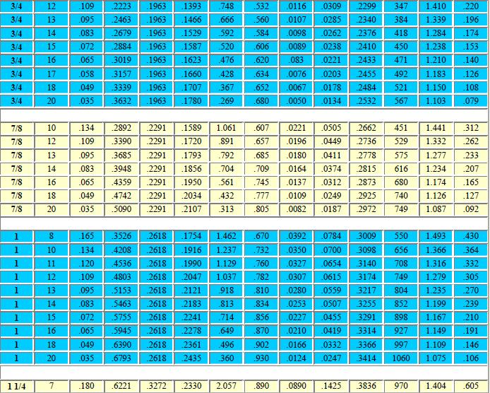
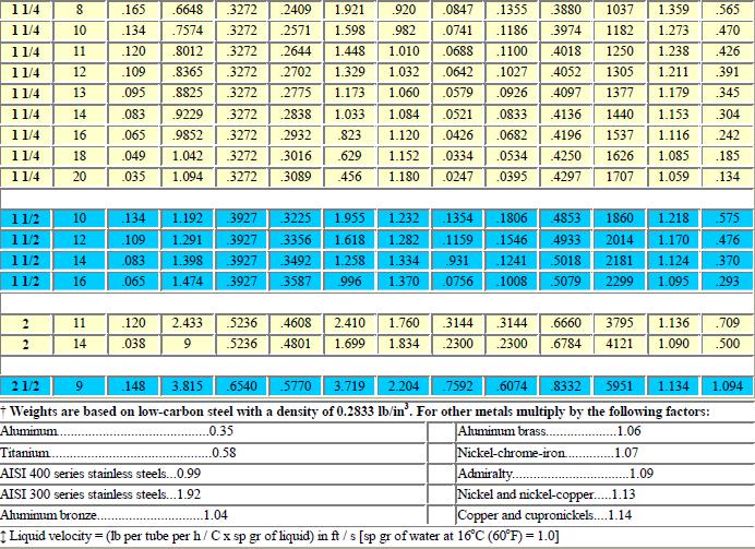
25 25 Tube Wall thickness and Diameter The wall thickness of heat exchanger tubes is standardized in terms of Birmingham Wire Gage BWG of the tube. Small tube diameters (8 to 15mm) are preferred for greater area to volume density but are limited for the purposes of cleaning. Large tube diameters are often required for condensers and boilers. From the heat transfer viewpoint, smaller-diameter tubes yield higher heat transfer coefficients and result in a more compact exchanger. However, larger-diameter tubes are easier to clean and more rugged. The foregoing common sizes represent a compromise. For chemical cleaning, smaller sizes can be used provided that the tubes never plug completely. The Stubs Iron Wire Gauge system (also known as the Birmingham Wire Gauge) is used to specify thickness or diameter of metal wire, strip, and tube products. Wall thickness of a pipe is normally given in decimal part of an inch rather than as fraction or gage number. When gauge numbers is given for a pipe without reference to a system, Birmingham Wire Gauge - BWG - is implied. The table shows the standardized data for commercial tubing obtained from BWG. The gauge starts at the lowest gauge number of 5Ø or 00000, corresponding to the largest size of 0.500" (12.7mm) to the highest gauge number of 36, corresponding to the smallest size of 0.004" (0.102mm) Birmingham Wire Gauge is also known as Stubs' Wire Gauge, used for drill rod and tool steel wire. The table on the next page shows some commercial tubing data with thickness, outer/inner diameter, and internal flow area, internal and external surface are per Ft. of length and weight of per Ft. of pipe of mild steel. (Detailed Chart: Appendix 1) Tube Length Thermal expansion of tubes needs to be taken into account for heat exchangers operating at elevated temperatures. But at the temperature difference of 20 o C 50 o C, deflection can be neglected. Tube elongation due to thermal expansion causes: Header plate deformation, Shell wall deformation near the header plate and Fatigue strength of the tube. Tube length also affects the cost and operation of heat exchangers. Longer the tube length (for any given surface area), Fewer tubes are needed, Shell diameter decreases resulting in lower cost. Shell-diameterto-tube-length ratio should be within limits of 1/5 to 1/15. Birmingham Wire Gage B.W.G. Gauge (inches) (5/0) (4/0) (3/0) (2/0)
26 26 Tube Layout Tube layout is characterized by the included angle between tubes. Two standard types of tube layouts are the square/ in-line and the staggered/ equilateral triangle. Triangular pitch (30 o layout) is better for heat transfer and surface area per unit length (greatest tube density.) Square pitch (45 & 90 layouts) is needed for mechanical cleaning. Note that the 30,45 and 60 are staggered, and 90 is in line. For the identical tube pitch and flow rates, the tube layouts in decreasing order of shell-side heat transfer coefficient and pressure drop are: 30,45,60, 90. The 90 layout will have the lowest heat transfer coefficient and the lowest pressure drop. The square pitch is generally not used in the fixed header sheet design because cleaning is not feasible.
27 27 The triangular pitch provides a more compact arrangement, usually resulting in smaller shell, and the strongest header sheet for a specified shell-side flow area. It is preferred when the operating pressure difference between the two fluids is large. Tube Pitch The selection of tube pitch is a compromise between a Close pitch (small values of Pt/do) for increased shell-side heat transfer and surface compactness, and an open pitch (large values of Pt/ do) for decreased shell-side plugging and ease in shell-side cleaning. Tube pitch (PT) is chosen so that the pitch ratio is 1.25 < PT/do < 1.5. When the tubes are too close to each other (Pt/do less than 1.25), the header plate (tube sheet) becomes too weak for proper rolling of the tubes and cause leaky joints. Fin Selection USE of FINS For a given LMTD the only way of increasing heat transfer rates in a heat-exchanger is to increase the surface area. One way of achieving this is through the use of extended or finned surfaces. With Liquid /Gas HX's very often the heat transfer coefficient on the liquid side is much greater than that on the gas side. Fins would then be used on the gas side so that the resistance to heat transfer was approximately the same on both sides. Fin comes in many shapes and sizes. They can be broadly classified into : Fins of constant cross-section : a)rectangular b) pin (spike) fins Fins of varying cross-section.: tapered fins. Fin geometry and density Fins improve heat transfer in two ways. One way is by creating turbulent flow through fin geometry, which reduces the thermal resistance (the inverse of the heat transfer coefficient) through the nearly stagnant film that forms when a fluid flows parallel to a solid surface. A second way is by increasing the fin density, which increases the heat transfer area that comes in contact with the fluid. Fin geometries and densities that create turbulent flow and improve performance also increase pressure drop, which is a critical requirement in most high performance applications. The optimum fin geometry and fin density combination is then a compromise of performance, pressure drop, weight, and size. Aside from fin geometry, parameters such as thickness, height, pitch, and spacing can also be altered to improve performance. Typically, fin thicknesses vary from in (0.1 mm) to in (0.3 mm), heights vary from in (0.89 mm) to 0.6 in (15.24 mm), and densities vary from 8 to 30 FPI (Fins Per Inch). In most high performance applications, fins are made of copper or aluminium. Aluminium fins are preferred in due to their lighter weight. There are many different fin geometries used in heat transfer applications. Some of the most commonly used are louvered, lanced offset, straight, and wavy fins. If we want to maximize heat transfer we must minimize thermal resistance. To accomplish this, we must increase the corresponding heat transfer areas, the film coefficients, or both. Increasing the heat transfer area is relatively easy in concept, though sometimes constrained by application requirements such as weight, size, and pressure drop. An effective way to increase the heat transfer area is to increase the fin density (fins per unit length). Increasing the film coefficient is more complicated, however, because the film coefficient is dependent upon the properties of the fluid being considered, the fluid velocity, and the fin geometry.
28 28 Fin Performance It is possible using methods we have already used to analyse the heat transfer characteristics (convection/ conduction) of fins. For long constant cross-section fins (where heat transfer through the tip is ignored (insulated), and assuming a constant heat transfer coefficient along its length, the temperature difference between the fin and the fluid is given by :- Where; Θ o = Temperature difference at the root of the fin (the wall m = (hp/λa) 1/2 p = perimeter of the fin cross-section; A = fin cross-sectional area; L = fin length Λ = thermal conductivity end); The heat transfer rate from the fin may be obtained by Determining the conduction at the root. For a comparatively short constant cross-section fin we cannot ignore the heat transfer at its tip, and when this is included we obtain:- Fin Efficiency / Effectiveness If the whole fin were at the wall (or root) temperature, the increase in heat transfer rate would be in direct proportion to the increase in surface area. Owing to the temperature gradient along a fin this is not achievable. We therefore define fin efficiency as:-

 for heat exchangers. In this case the fins are on the 'h1' side. Although analysis of varying cross-section fins is more complex than for constant crosssection fins, it can be done (!")
29 29 For long constant cross-section fins this is: For short constant cross-section fins this is: Finned Surfaces If A = total surface area (including fin area), and A fin = fin surface area, let b = A fin /A. The total heat transfer from a finned surface is then given by:- η' = 1 - b (1 - η fin) is the area weighted fin efficiency η ' can be incorporated into the calculation for the overall heat transfer coefficient (U) for heat exchangers. In this case the fins are on the 'h1' side. Although analysis of varying cross-section fins is more complex than for constant crosssection fins, it can be done (!), and graphs are available which give fin efficiency as a function of their geometry and dimensions. These can be used to estimate the heat transfer enhancement achieved by using these types of fins.
30 30 Fan Discharge The air flow and the air speed between ribs of frame must meet minimum the figures given below as to shaft height. Figures correspond 50 Hz ne t supply, with 60 Hz 20 % must be added.
31

32 32 Appendix 1: Tube Specifications
33
34 34 Appendix 2: Air Properties Tempera ture Density Specific heat capacity Thermal conducti vity Kinematic viscosity Expansion coefficient Prandtl's number - t c p - - l - - ν - - b - - P r - ( o C) (kg/m 3 ) (kj/kg.k) (W/m.K) x 10-6 (m 2 /s) x 10-3 (1/K)
Heat Exchangers (Chapter 5)
") Heat Exchangers (Chapter 5) 2 Learning Outcomes (Chapter 5) Classification of heat exchangers Heat Exchanger Design Methods Overall heat transfer coefficient LMTD method ε-ntu method Heat Exchangers Pressure
Heat Exchangers (Chapter 5) 2 Learning Outcomes (Chapter 5) Classification of heat exchangers Heat Exchanger Design Methods Overall heat transfer coefficient LMTD method ε-ntu method Heat Exchangers Pressure
Thermal Unit Operation (ChEg3113)
") Thermal Unit Operation (ChEg3113) Lecture 9- Shell and Tube Heat Exchanger Design Instructor: Mr. Tedla Yeshitila (M.Sc.) Today Review Shell and tube heat exchanger Steps in Shell and tube heat exchanger
Thermal Unit Operation (ChEg3113) Lecture 9- Shell and Tube Heat Exchanger Design Instructor: Mr. Tedla Yeshitila (M.Sc.) Today Review Shell and tube heat exchanger Steps in Shell and tube heat exchanger
Lecture 2: Thermal Design Considerations
 Lecture 2: Thermal Design Considerations The flow rates of both hot and cold streams, their terminal temperatures and fluid properties are the primary inputs of thermal design of heat exchangers. 1.2.
Design and Performance Study of Shell and Tube Heat Exchanger with Single Segmental Baffle Having Perpendicular & Parallel-Cut Orientation.
 Design and Performance Study of Shell and Tube Heat Exchanger with Single Segmental Baffle Having Perpendicular & Parallel-Cut Orientation. Swarup S Deshpande Mechanical Engineering Intern Excel Plants
Thermal Unit Operation (ChEg3113)
") Thermal Unit Operation (ChEg3113) Lecture 5- Heat Exchanger Design Instructor: Mr. Tedla Yeshitila (M.Sc.) Today Review Heat exchanger design vs rating of heat exchanger Heat exchanger general design procedure
Thermal Unit Operation (ChEg3113) Lecture 5- Heat Exchanger Design Instructor: Mr. Tedla Yeshitila (M.Sc.) Today Review Heat exchanger design vs rating of heat exchanger Heat exchanger general design procedure
EXPERIMENTAL INVESTIGATIONS OF DOUBLE PIPE HEAT EXCHANGER WITH TRIANGULAR BAFFLES
 International Research Journal of Engineering and Technology (IRJET) e-issn: 2395-56 Volume: 3 Issue: 8 Aug-216 www.irjet.net p-issn: 2395-72 EXPERIMENTAL INVESTIGATIONS OF DOUBLE PIPE HEAT EXCHANGER WITH
Thermal Analysis of Shell and Tube Heat Exchanger Using Different Fin Cross Section
 Thermal Analysis of Shell and Tube Heat Exchanger Using Different Fin Cross Section J. Heeraman M.Tech -Thermal Engineering Department of Mechanical Engineering Ellenki College of Engineering & Technology
MULTIPLE PASS AND CROSS FLOW HEAT EXCHANGERS
 MULTIPLE PASS AND CROSS FLOW HEAT Introduction EXCHANGERS In order to increase the surface area for convection relative to the fluid volume, it is common to design for multiple tubes within a single heat
Heat Exchanger Design
 CH2407 Process Equipment Design II Heat Exchanger Design Dr. M. Subramanian Associate Professor Department of Chemical Engineering Sri Sivasubramaniya Nadar College of Engineering Kalavakkam 603 110, Kanchipuram
Experiment No: 2. To determine the effectiveness of shell and tube, cross flow & plate heat exchangers. Heat Exchangers. Plate-type Extended surfaces
 Experiment No: Objective o determine the effectiveness of shell and tube, cross & plate heat exchangers heory A heat exchanger is an equipment which facilitates the of thermal energy between two or more
Design and Fabrication of Shell and Tube Type Heat Exchanger and Performance Analysis
 Design and Fabrication of Shell and Tube Type Heat Exchanger and Performance Analysis Tanveer Raza 1, Marooph Patel 2. 1 Student, Mechanical Engineering Department, SKN, tanveer.raza23@gmail.com 2 Student,
Comparison of Heat transfer Enhancement in Tube in Tube heat exchanger using Different Turbulent Generator.
 INSTITUTE OF TECHNOLOGY, NIRMA UNIVERSITY, AHMEDABAD 382 481, 8-10 DECEMBER, 2011 1 Comparison of Heat transfer Enhancement in Tube in Tube heat exchanger using Different Turbulent Generator. A. Mehta
A Review on Experimental Investigation of U-Tube Heat Exchanger using Plain Tube and Corrugated Tube
 A Review on Experimental Investigation of U-Tube Heat Exchanger using Plain Tube and Corrugated Tube 1 Dhavalkumar A. Maheshwari, 2 Kartik M. Trivedi 1 ME Student, 2 Assistant Professor 1 Mechanical Engineering
Design, Fabrication and Testing of helical tube in tube coil heat exachanger
 Design, Fabrication and Testing of helical tube in tube coil heat exachanger #1 Sachin Meshram, #2 Prof.P.T.Nitnaware, #3 M.R.Jagdale ABSTRACT Helical coil heat exchangers are one of the most common equipment
Exhaust Gas Waste Heat Recovery and Utilization System in IC Engine
 IJIRST International Journal for Innovative Research in Science & Technology Volume 1 Issue 11 April 2015 ISSN (online): 2349-6010 Exhaust Gas Waste Heat Recovery and Utilization System in IC Engine Alvin
Heat Transfer Enhancement for Double Pipe Heat Exchanger Using Twisted Wire Brush Inserts
 Heat Transfer Enhancement for Double Pipe Heat Exchanger Using Twisted Wire Brush Inserts Deepali Gaikwad 1, Kundlik Mali 2 Assistant Professor, Department of Mechanical Engineering, Sinhgad College of
Performance Evaluation Of A Helical Baffle Heat Exchanger
 Performance Evaluation Of A Helical Baffle Heat Exchanger Mayank Vishwakarma 1, Professor. K. K. Jain 2 1 M.E IV Semester (Heat Power Engineering) Shri Ram Institute of Technology, Jabalpur 482002 (M.P)
Heat Transfer in Rectangular Duct with Inserts of Triangular Duct Plate Fin Array
 Heat Transfer in Rectangular Duct with Inserts of Triangular Duct Plate Fin Array Deepak Kumar Gupta M. E. Scholar, Raipur Institute of Technology, Raipur (C.G.) Abstract: In compact plate fin heat exchanger
THERMAL ANALYSIS OF SHELL AND TUBE HEAT EXCHANGER
 International Journal of Mechanical Engineering and Technology (IJMET) Volume 8, Issue 5, May 2017, pp. 596 606, Article ID: IJMET_08_05_066 Available online at http://www.ia aeme.com/ijmet/issues.asp?jtype=ijmet&vtyp
THERMAL ANALYSIS OF HELICALLY GROOVED COIL IN A CONCENTRIC TUBE HEAT EXCHANGER
 THERMAL ANALYSIS OF HELICALLY GROOVED COIL IN A CONCENTRIC TUBE HEAT EXCHANGER A. RESHMA P.G Scholar, Thermal Engineering, Aditya Engineering College, Surampalem M.SREENIVASA REDDY Professor, Mechanical
DESIGN OPTIMIZATION OF SHELL AND TUBE HEAT EXCHANGER FOR OIL COOLER BY COMSOL MULTIPHYSIS
 DESIGN OPTIMIZATION OF SHELL AND TUBE HEAT EXCHANGER FOR OIL COOLER BY COMSOL MULTIPHYSIS 1 SU PON CHIT, 2 NYEIN AYE SAN, 3 MYAT MYAT SOE 1,2,3 Department of Mechanical Engineering, Mandalay Technological
Quality Improvement in Design Process of Shell & Tube Type Heat Exchanger by Computer Integrated 3D Modeling
 Quality Improvement in Design Process of Shell & Tube Type Heat Exchanger by Computer Integrated 3D Modeling Prof. V. N. Mane 1 1] Assistant Professor, Department of Mechanical Engineering, T.K.I.E.T.
COMPUTATIONAL ANALYSIS TO MAXIMIZE THE HEAT TRANSFER RATE OF DOUBLE TUBE HELICAL COIL HEAT EXCHANGER
 COMPUTATIONAL ANALYSIS TO MAXIMIZE THE HEAT TRANSFER RATE OF DOUBLE TUBE HELICAL COIL HEAT EXCHANGER Ramesh Babu. T #1, Krishna Kishore.K #2, Nithin Kumar.P #3 # Mechanical Department, Narasaraopeta Engineering
ENGINEERING STANDARD FOR PROCESS DESIGN OF DOUBLE PIPE HEAT EXCHANGERS ORIGINAL EDITION JULY 1995
 ENGINEERING STANDARD FOR PROCESS DESIGN OF DOUBLE PIPE HEAT EXCHANGERS ORIGINAL EDITION JULY 1995 This standard specification is reviewed and updated by the relevant technical committee on June 2000. The
The Practical Uses of Computational Fluid Dynamics Not Just a Pretty Picture
 The Practical Uses of Computational Fluid Dynamics Not Just a Pretty Picture Presenter: William Osley Company: CALGAVIN Ltd Email: william.osley@calgavin.com Page 1 Contents: Introduction Case Study 1:
Design of Shell and Tube Type Heat Exchanger using CFD Tools
 IJIRST International Journal for Innovative Research in Science & Technology Volume 4 Issue 3 August 2017 ISSN (online): 2349-6010 Design of Shell and Tube Type Heat Exchanger using CFD Tools Devvrat Verma
Pilan. Hydraulic Oil Coolers and Heat Exchangers
 Pilan Hydraulic Coolers and Heat Exchangers www.comeval.es Toraflex - is a trademark of Comeval Valve Systems Data subject to change without prior notice Pilan Hydraulic Coolers and Heat Exchangers Index
NOVATEUR PUBLICATIONS INTERNATIONAL JOURNAL OF INNOVATIONS IN ENGINEERING RESEARCH AND TECHNOLOGY [IJIERT] VOLUME 1, ISSUE 1 NOV-2014
![NOVATEUR PUBLICATIONS INTERNATIONAL JOURNAL OF INNOVATIONS IN ENGINEERING RESEARCH AND TECHNOLOGY [IJIERT] VOLUME 1, ISSUE 1 NOV-2014](/thumbs/87/97066795.jpg "NOVATEUR PUBLICATIONS INTERNATIONAL JOURNAL OF INNOVATIONS IN ENGINEERING RESEARCH AND TECHNOLOGY [IJIERT] VOLUME 1, ISSUE 1 NOV-2014") Review of Heat Transfer Parameters using internal threaded pipe fitted with inserts of different materials Mr. D.D.Shinde Department of Mechanical Engineering Shivaji University, PVPIT Budhagaon, Dist:
Review of Heat Transfer Parameters using internal threaded pipe fitted with inserts of different materials Mr. D.D.Shinde Department of Mechanical Engineering Shivaji University, PVPIT Budhagaon, Dist:
LESSON Transmission of Power Introduction
 LESSON 3 3.0 Transmission of Power 3.0.1 Introduction Earlier in our previous course units in Agricultural and Biosystems Engineering, we introduced ourselves to the concept of support and process systems
EXPERIMENTAL ANALYSIS AND PERFORMANCE CHARACTERISTIC OF HEAT TRANSFER IN SHELL AND TWISTED TUBE HEAT EXCHANGER
 International Journal of Emerging Technology and Innovative Engineering Volume 1, Issue 11, November 2015 (ISSN: 2394 6598) EXPERIMENTAL ANALYSIS AND PERFORMANCE CHARACTERISTIC OF HEAT TRANSFER IN SHELL
Thermal Stress Analysis of Diesel Engine Piston
 International Conference on Challenges and Opportunities in Mechanical Engineering, Industrial Engineering and Management Studies 576 Thermal Stress Analysis of Diesel Engine Piston B.R. Ramesh and Kishan
TO STUDY OF PARAMETRIC ANALYSIS OF SHELL AND TUBE HEAT EXCHENGER
 TO STUDY OF PARAMETRIC ANALYSIS OF SHELL AND TUBE HEAT EXCHENGER Durgesh Rai 1, Sunil Bharati 2, Sohail Bux 3 1 P.G Research Scholar, Department of Thermal Engineering, Agnos college of Technology, RKDF
COMPRESSIBLE FLOW ANALYSIS IN A CLUTCH PISTON CHAMBER
 COMPRESSIBLE FLOW ANALYSIS IN A CLUTCH PISTON CHAMBER Masaru SHIMADA*, Hideharu YAMAMOTO* * Hardware System Development Department, R&D Division JATCO Ltd 7-1, Imaizumi, Fuji City, Shizuoka, 417-8585 Japan
Single-phase Coolant Flow and Heat Transfer
 22.06 ENGINEERING OF NUCLEAR SYSTEMS - Fall 2010 Problem Set 5 Single-phase Coolant Flow and Heat Transfer 1) Hydraulic Analysis of the Emergency Core Spray System in a BWR The emergency spray system of
PV Newsletter Monthly Publication from CoDesign Engineering Skills Academy
 April 15, 2013 PV Newsletter Monthly Publication from CoDesign Engineering Skills Academy www.codesignengg.com This article has some reproductions from the PV Newsletter - Volume 1, Issue 10 contributed
CFD Investigation of Influence of Tube Bundle Cross-Section over Pressure Drop and Heat Transfer Rate
 CFD Investigation of Influence of Tube Bundle Cross-Section over Pressure Drop and Heat Transfer Rate Sandeep M, U Sathishkumar Abstract In this paper, a study of different cross section bundle arrangements
Applied Fluid Mechanics
 Applied Fluid Mechanics 1. The Nature of Fluid and the Study of Fluid Mechanics 2. Viscosity of Fluid 3. Pressure Measurement 4. Forces Due to Static Fluid 5. Buoyancy and Stability 6. Flow of Fluid and
Cross Flow Heat Exchanger H352
 Cross Flow Heat Exchanger H352 H352 Cross Flow Heat Exchanger Shown With Optional Plain Tube of H352A fitted. Allows Investigation Of Plain And Finned Cross Flow Heat Exchangers. Expandable Free & Forced
CONSTRUCTION AND ANALYSIS OF TUBE IN TUBE TYPE HEAT EXCHANGER
 CONSTRUCTION AND ANALYSIS OF TUBE IN TUBE TYPE HEAT EXCHANGER N. S. Panchal 1, O. V. Pathak 2, G. P. Chaudhari 3, A. H. Paulkar 4, Asst. Prof. B. M. Dusane 5 Department of mechanical engineering, Sandip
CONJUGATE HEAT TRANSFER ANALYSIS OF HELICAL COIL HEAT EXCHANGE USING CFD
 CONJUGATE HEAT TRANSFER ANALYSIS OF HELICAL COIL HEAT EXCHANGE USING CFD Rudragouda R Patil 1, V Santosh Kumar 2, R Harish 3, Santosh S Ghorpade 4 1,3,4 Assistant Professor, Mechanical Department, Jayamukhi
Experimental Analysis and Performance Characteristic Of Heat Transfer In Shell and Twisted Tube Heat Exchanger.
 Experimental Analysis and Performance Characteristic Of Heat Transfer In Shell and Twisted Tube Heat Exchanger. Nitesh B. Dahare 1, Dr. M. Basavaraj 2 1 Student,M.Tech. Heat Power Engineering, Dept.of
ADVANCES in NATURAL and APPLIED SCIENCES
 ADVANCES in NATURAL and APPLIED SCIENCES ISSN: 1995-772 Published BY AENSI Publication EISSN: 1998-19 http://www.aensiweb.com/anas 216 Special1(7): pages 69-74 Open Access Journal Enhancement Of Heat Transfer
FLUID FLOW. Introduction
 FLUID FLOW Introduction Fluid flow is an important part of many processes, including transporting materials from one point to another, mixing of materials, and chemical reactions. In this experiment, you
Design and experimental analysis of pipe in pipe heat exchanger
 International OPEN ACCESS Journal Of Modern Engineering Research (IJMER) Design and experimental analysis of pipe in pipe heat exchanger Ojha Pramod Kailash 1, Choudhary Bishwajeet NK 2, Gajera Umang B
COLD PLATE SOFTWARE PROGRAM ANALYZES AIRCRAFT
 COLD PLATE SOFTWARE PROGRAM ANALYZES AIRCRAFT DISPLAY T. Renaud Sanders, a Lockheed Martin Co. Nov, 2000 Introduction Finned heat exchangers, called cold plates, have been used for many years to cool military
Part C: Electronics Cooling Methods in Industry
 Part C: Electronics Cooling Methods in Industry Indicative Contents Heat Sinks Heat Pipes Heat Pipes in Electronics Cooling (1) Heat Pipes in Electronics Cooling (2) Thermoelectric Cooling Immersion Cooling
 DEPARTMENT OF MECHANICAL ENGINEERING Subject code: ME6601 Subject Name: DESIGN OF TRANSMISSION SYSTEMS UNIT-I DESIGN OF TRANSMISSION SYSTEMS FOR FLEXIBLE ELEMENTS 1. What is the effect of centre distance
CFD analysis of heat transfer enhancement in helical coil heat exchanger by varying helix angle
 CFD analysis of heat transfer enhancement in helical coil heat exchanger by varying helix 1 Saket A Patel, 2 Hiren T Patel 1 M.E. Student, 2 Assistant Professor 1 Mechanical Engineering Department, 1 Mahatma
Delivering unsurpassed quality, design and value.
 Delivering unsurpassed quality, design and value. Exergy has been a leading global supplier of heat transfer solutions for over twenty-five years. We utilize state-of-the-art design and manufacturing techniques
Optimisation of Double Pipe Helical Tube Heat Exchanger and its Comparison with Straight Double Tube Heat Exchanger
 DOI 1.17/s432-16-261-x ORIGINAL CONTRIBUTION Optimisation of Double Pipe Helical Tube Heat Exchanger and its Comparison with Straight Double Tube Heat Exchanger Rashid Kareem 1 Received: 3 June 214 / Accepted:
CHAPTER 19 DC Circuits Units
 CHAPTER 19 DC Circuits Units EMF and Terminal Voltage Resistors in Series and in Parallel Kirchhoff s Rules EMFs in Series and in Parallel; Charging a Battery Circuits Containing Capacitors in Series and
International Journal of Advance Engineering and Research Development
 Scientific Journal of Impact Factor (SJIF): 4.14 International Journal of Advance Engineering and Research Development Volume 3, Issue 5, May -2016 e-issn (O): 2348-4470 p-issn (P): 2348-6406 Increase
Design Optimization of Cross Flow Heat Exchanger
 Design Optimization of Cross Flow Heat Exchanger K. Ashok Kumar Raju 1, M. Vijay Kumar Reddy 2, A. Nagaraja 3 1,2,3 Department of Mechanical Engineering, A.I.T.S, Rajampet Abstract Heat exchangers are
Plate Heat Exchangers
 Plate Heat Exchangers Alok Garg 2 Alok Garg 3 Alok Garg 4 Alok Garg 5 Purpose of the Equipment: Plate heat exchangers (PHE), often called plate-and-frame heat exchangers, are used to change the temperature
CFD analysis of triple concentric tube heat exchanger
 Available online at www.ganpatuniversity.ac.in University Journal of Research ISSN (Online) 0000 0000, ISSN (Print) 0000 0000 CFD analysis of triple concentric tube heat exchanger Patel Dharmik A a, V.
EFFECT OF UNCONSTANT OVERALL HEAT TRANSFER COEFFICIENT ON THERMAL PERFORMANCES OF MULTIPLE ASSEMBLIES OF AUTOMOBILE RADIATORS
 EFFECT OF UNCONSTANT OVERALL HEAT TRANSFER COEFFICIENT ON THERMAL PERFORMANCES OF MULTIPLE ASSEMBLIES OF AUTOMOBILE RADIATORS S. Vithayasai T.Kiatsiriroat Department of Mechanical Engineering, Chiang Mai
An Overview of Shell & Tube Type Heat Exchanger Design by Kern s Method
 Available online at www.ijiere.com International Journal of Innovative and Emerging Research in Engineering e-issn: 2394-3343 p-issn: 2394-5394 An Overview of Shell & Tube Type Heat Exchanger Design by
IJESR/Oct 2012/ Volume-2/Issue-10/Article No-12/ ISSN International Journal of Engineering & Science Research
 International Journal of Engineering & Science Research DESIGN AND CFD ANALYSIS OF U TUBE HEAT EXCHANGER P.B. Borade* 1, K.V.Mali 2 1 P.G. Student, Mechanical Department, Sinhgad College of Engineering,
HEAT EXCHANGER OVERVIEW
 HEAT EXCHANGERS 1 PURPOSE A heat exchanger is an apparatus performing heat exchange between two or several fluids. It can carry out this task by: Segregating the fluids and making them exchange heat through
DESIGN AND ANALYSIS OF UNDERTRAY DIFFUSER FOR A FORMULA STYLE RACECAR
 DESIGN AND ANALYSIS OF UNDERTRAY DIFFUSER FOR A FORMULA STYLE RACECAR Ali Asgar S. Khokhar 1, Suhas S. Shirolkar 2 1 Graduate in Mechanical Engineering, KJ Somaiya College of Engineering, Mumbai, India.
International Journal of Scientific & Engineering Research, Volume 6, Issue 10, October ISSN
 International Journal of Scientific & Engineering Research, Volume 6, Issue 0, October-205 97 The Effect of Pitch and Fins on Enhancement of Heat Transfer in Double Pipe Helical Heat Exchanger 2 Abdulhassan
Prediction of Thermal Deflection at Spindle Nose-tool Holder Interface in HSM
 Prediction of Thermal Deflection at Spindle Nose-tool Holder Interface in HSM V Prabhu Raja, J Kanchana, K Ramachandra, P Radhakrishnan PSG College of Technology, Coimbatore - 641004 Abstract Loss of machining
Design and Performance Analysis of Louvered Fin Automotive Radiator using CAE Tools
 Design and Performance Analysis of Louvered Fin Automotive Radiator using CAE Tools Vishwa Deepak Dwivedi Scholar of Master of Technology, Mechanical Engineering Department, UCER, Allahabad, India Ranjeet
International Journal of World Research, Vol: I Issue XXXVII, January 2017 Print ISSN: X
 EFFECTS ON HEAT TRANSFER RATE FOR SHELL SIDE IN TEMA E-TYPE SHELL AND TUBE HEAT EXCHANGERS DUE TO VARIATION IN THE BAFFLE CUT PERCENTAGE USING CFD SOFTWARE Devanand D Chillal Research Scholar, Department
Modeling and Fluid Flow Analysis of Wavy Fin Based Automotive Radiator
 RESEARCH ARTICLE OPEN ACCESS Modeling and Fluid Flow Analysis of Wavy Fin Based Automotive Radiator Vishwa Deepak Dwivedi, Ranjeet Rai Scholar of Master of Technology, Mechanical Engineering Department,
Silencers. Transmission and Insertion Loss
 Silencers Practical silencers are complex devices, which operate reducing pressure oscillations before they reach the atmosphere, producing the minimum possible loss of engine performance. However they
Cross Flow Heat Exchanger H352
 Cross Flow Heat Exchanger H352 H352 Shown With Optional Plain Tube of H352A fitted. Allows Investigation Of Plain And Finned Cross Flow Heat Exchangers. Expandable Free & Forced Convection Heat Transfer
Experimental investigation of shell-and-tube heat exchanger with different type of baffles
 International Journal of Current Engineering and Technology E-ISSN 2277 416, P-ISSN 2347 5161 216 INPRESSCO, All Rights served Available at http://inpressco.com/category/ijcet search Article Experimental
Computer-Assisted Induction Aluminum
 Home Computer-Assisted Induction Aluminum Brazing November 11, 2003 Coupled electromagnetic and thermal computer simulation provides a sufficient basis for process optimization and quality improvement
PEIRCE SMITH CONVERTER HOOD IMPROVEMENTS AT BHP COPPER
 PEIRCE SMITH CONVERTER HOOD IMPROVEMENTS AT BHP COPPER Ovidiu Pasca and John Bryant BHP Copper Arizona, USA Paykan Safe and Brian Wiggins Gas Cleaning Technologies Dallas, USA ABSTRACT Several improvements
PERFOMANCE UPGRADING OF ENGINE BY OIL COOLING SYSTEM
 PERFOMANCE UPGRADING OF ENGINE BY OIL COOLING SYSTEM Kiran Kenny, Shibu Augustine, Prasidh E Prakash,Arjun G Nair Malabar College of Engineering and Technology, Kerala Technological University kirankenny33@gmail.com,
ECH 4224L Unit Operations Lab I Fluid Flow FLUID FLOW. Introduction. General Description
 FLUID FLOW Introduction Fluid flow is an important part of many processes, including transporting materials from one point to another, mixing of materials, and chemical reactions. In this experiment, you
NUMERICAL SIMULATION OF HELICAL COIL TUBE IN TUBE HEAT EXCHANGER WITH BAFFLES
 M tech thesis NUMERICAL SIMULATION OF HELICAL COIL TUBE IN TUBE HEAT EXCHANGER WITH BAFFLES A REPORT SUBMITTED IN PARTIAL FULFILMENT OF THE REQUIREMENTS FOR THE DEGREE OF Master of Technology In Thermal
TRANSLATION (OR LINEAR)
") 5) Load Bearing Mechanisms Load bearing mechanisms are the structural backbone of any linear / rotary motion system, and are a critical consideration. This section will introduce most of the more common
5) Load Bearing Mechanisms Load bearing mechanisms are the structural backbone of any linear / rotary motion system, and are a critical consideration. This section will introduce most of the more common
DESIGN AND ANALYSIS OF CAR RADIATOR BY FINITE ELEMENT METHOD
 DESIGN AND ANALYSIS OF CAR RADIATOR BY FINITE ELEMENT METHOD Prof. V. C. Pathade 1, Sagar R. Satpute 2, Mayur G. Lajurkar 3, Gopal R. Pancheshwar 4 Tushar K. Karluke 5, Niranjan H. Singitvar 6 1 Assistant
Pump Control Ball Valve for Energy Savings
 VM PCBVES/WP White Paper Pump Control Ball Valve for Energy Savings Table of Contents Introduction............................... Pump Control Valves........................ Headloss..................................
Optimization of Packed Tower Inlet Design by CFD Analysis. Dana Laird Koch-Glitsch, Inc.
 39e Optimization of Packed Tower Inlet Design by CFD Analysis Dana Laird Koch-Glitsch, Inc. Brian Albert ExxonMobil Research and Engineering (formerly with Koch-Glitsch, Inc.) Carol Schnepper John Zink
Experimental Investigation of Heat Transfer characteristics Enhancement through Grooved Tube
 International Journal of Current Engineering and Technology E-ISSN 2277 46, P-ISSN 2347 5161 216 INPRESSCO, All Rights served Available at http://inpressco.com/category/ijcet search Article Experimental
SHELL & TUBE HEAT EXCHANGER
 SHELL & TUBE HEAT EXCHANGER ASERA Heat ransfer T A N a m e M o v e s around the world ASERA Heat ransfer T A N a m e M o v e s around the world KASERA Heat Transfer Pvt. Ltd. was established in 1955.
Technical Notes by Dr. Mel
 Technical Notes by Dr. Mel April 2009 Solving Ring-Oiled Bearing Problems In recent years, TRI has encountered and resolved a number of problems with ring-oiled bearings for fans, motors, and pumps. Oiling
CFD ANALYSIS OF DOUBLE HELICAL PIPE PARALLEL& COUNTER FLOW HEAT EXCHANGER
 CFD ANALYSIS OF DOUBLE HELICAL PIPE PARALLEL& COUNTER FLOW Abstract HEAT EXCHANGER 1 Hepsiba Sudarsanam, 2 Dvsrbm Subhramanyam 1 PG Scholar, Department of MECH, Nalanda Institute of Technology, Kantepudi,Sattenapalli
Review on Comparative Study between Straight Tube Heat Exchanger and Helical Coil Heat Exchanger
 Review on Comparative Study between Straight Tube Heat Exchanger and Helical Coil Heat Exchanger Vaibhav M. Samant 1, Jayesh V. Bute 2 1 (Student (Mechanical Engineering)/Pimpri Chinchwad College Of Engineering
Chapter 7: DC Motors and Transmissions. 7.1: Basic Definitions and Concepts
 Chapter 7: DC Motors and Transmissions Electric motors are one of the most common types of actuators found in robotics. Using them effectively will allow your robot to take action based on the direction
FLOW AND HEAT TRANSFER ENHANCEMENT AROUND STAGGERED TUBES USING RECTANGULAR VORTEX GENERATORS
 FLOW AND HEAT TRANSFER ENHANCEMENT AROUND STAGGERED TUBES USING RECTANGULAR VORTEX GENERATORS Prabowo, Melvin Emil S., Nanang R. and Rizki Anggiansyah Department of Mechanical Engineering, ITS Surabaya,
Technical Guide No. 7. Dimensioning of a Drive system
 Technical Guide No. 7 Dimensioning of a Drive system 2 Technical Guide No.7 - Dimensioning of a Drive system Contents 1. Introduction... 5 2. Drive system... 6 3. General description of a dimensioning
An Experimental Study of Thermo-Hydraulic Performance of Modified Double Pipe Heat Exchanger Using Mesh Inserts
 An Experimental Study of Thermo-Hydraulic Performance of Modified Double Pipe Heat Exchanger Using Mesh Inserts Prof.A.M.Patil 1, M.R.Todkar 2 Professor, Department of Mechanical Engineering, PVPIT, Budhgaon,
CFD ANALYSIS ON LOUVERED FIN
 CFD ANALYSIS ON LOUVERED FIN P.Prasad 1, L.S.V Prasad 2 1Student, M. Tech Thermal Engineering, Andhra University, Visakhapatnam, India 2Professor, Dept. of Mechanical Engineering, Andhra University, Visakhapatnam,
FUNDAMENTAL SAFETY OVERVIEW VOLUME 2: DESIGN AND SAFETY CHAPTER E: THE REACTOR COOLANT SYSTEM AND RELATED SYSTEMS
 PAGE : 1 / 13 4. PRESSURISER 4.1. DESCRIPTION The pressuriser (PZR) is a pressurised vessel forming part of the reactor coolant pressure boundary (CPP) [RCPB]. It comprises a vertical cylindrical shell,
A comparative analysis to enhance the effectiveness of EGR coolers used in diesel engine
 A comparative analysis to enhance the effectiveness of EGR coolers used in diesel engine 1 Ibrahim Hussein Shah, 2 Bhupendra Singh, 1 Assistant Professor, 2 PG scholar, 1 Department of Mechanical Engineering,
CHAPTER 3 DESIGN OF THE LIMITED ANGLE BRUSHLESS TORQUE MOTOR
 33 CHAPTER 3 DESIGN OF THE LIMITED ANGLE BRUSHLESS TORQUE MOTOR 3.1 INTRODUCTION This chapter presents the design of frameless Limited Angle Brushless Torque motor. The armature is wound with toroidal
ENHANCEMENT OF HEAT TRANSFER COEFFICIENT THROUGH HELICAL COIL
 ENHANCEMENT OF HEAT TRANSFER COEFFICIENT THROUGH HELICAL COIL Rahul G.Karmankar Assistant Professor, Mechanical Engineering department,nagpur University, Maharashtra,India ---------------------------------------------------------------------***---------------------------------------------------------------------
International Journal of Advance Engineering and Research Development
 Scientific Journal of Impact Factor (SJIF): 3.134 International Journal of Advance Engineering and Research Development Volume 2, Issue 12, December -2015 e-issn (O): 2348-4470 p-issn (P): 2348-6406 An
ABSTRACT I. INTRODUCTION III. GEOMETRIC MODELING II. LITERATURE REVIW
 2017 IJSRSET Volume 3 Issue 5 Print ISSN: 2395-1990 Online ISSN : 2394-4099 Themed Section: Engineering and Technology Performance Analysis of Helical Coil Heat Exchanger Using Numerical Technique Abhishek
Enhanced Heat Transfer Surface Development for Exterior Tube Surfaces
 511 A publication of CHEMICAL ENGINEERING TRANSACTIONS VOL. 32, 2013 Chief Editors: Sauro Pierucci, Jiří J. Klemeš Copyright 2013, AIDIC Servizi S.r.l., ISBN 978-88-95608-23-5; ISSN 1974-9791 The Italian
(12) Patent Application Publication (10) Pub. No.: US 2011/ A1
 Patent Application Publication (10) Pub. No.: US 2011/ A1") (19) United States (12) Patent Application Publication (10) Pub. No.: US 2011/0226455A1 Al-Anizi et al. US 2011 0226455A1 (43) Pub. Date: Sep. 22, 2011 (54) (75) (73) (21) (22) SLOTTED IMPINGEMENT PLATES
(19) United States (12) Patent Application Publication (10) Pub. No.: US 2011/0226455A1 Al-Anizi et al. US 2011 0226455A1 (43) Pub. Date: Sep. 22, 2011 (54) (75) (73) (21) (22) SLOTTED IMPINGEMENT PLATES
2.61 Internal Combustion Engines Spring 2008
 MIT OpenCourseWare http://ocw.mit.edu 2.61 Internal Combustion Engines Spring 2008 For information about citing these materials or our Terms of Use, visit: http://ocw.mit.edu/terms. Engine Heat Transfer
Effects of Dilution Flow Balance and Double-wall Liner on NOx Emission in Aircraft Gas Turbine Engine Combustors
 Effects of Dilution Flow Balance and Double-wall Liner on NOx Emission in Aircraft Gas Turbine Engine Combustors 9 HIDEKI MORIAI *1 Environmental regulations on aircraft, including NOx emissions, have
Efficiency Improvement in Shell and Tube Heat Exchanger Using CFD Tool
 Efficiency Improvement in Shell and Tube Heat Exchanger Using CFD Tool Mohan.K [1], Prakash.K [2], Sathya Samy.C [3] P.G Scholar, SNS College of Technology, Coimbatore, India [1][3] Assistant Professor,
Chapter 7: Thermal Study of Transmission Gearbox
 Chapter 7: Thermal Study of Transmission Gearbox 7.1 Introduction The main objective of this chapter is to investigate the performance of automobile transmission gearbox under the influence of load, rotational
TE 73 TWO ROLLER MACHINE
 TE 73 TWO ROLLER MACHINE Background The TE 73 family of machines dates back to original Plint and Partners Ltd designs from the 1960s. These machines are all to the overhung roller design in which test