Impeller Disc Mower Conditioner
|
|
|
- Colleen Gray
- 6 years ago
- Views:
Transcription
1 252 Form No Revision B Impeller Disc Mower Conditioner OPERATOR S MANUAL
2 GEHL NEW AGRICULTURAL EQUIPMENT IMPELLER DISC MOWER CONDITIONER WARRANTY GEHL AGRICULTURE DIVISION of the GEHL COMPANY, hereinafter referred to as Gehl, warrants new Gehl Impeller Disc Mower Conditioners and attachments to the Original Retail Purchaser to be free from defects in material and workmanship for a period of twelve (2) months {ninety (90) days for commercial/custom use} from the Warranty Start Date: GEHL AGRICULTURE WARRANTY INCLUDES: Genuine Gehl parts and labor costs required to repair or replace equipment at the selling dealer s business location. GEHL MAKES NO REPRESENTATIONS OR WARRANTIES OF ANY KIND, EXPRESS OR IMPLIED (INCLUDING THE IMPLIED WARRANTIES OF MERCHANTABILITY AND FITNESS FOR PARTICULAR PURPOSE), EXCEPT AS EXPRESSLY STATED IN THIS WARRANTY STATEMENT. GEHL WARRANTY DOES NOT INCLUDE:. Transportation to selling dealer s business location or, at the option of the Original Retail Purchaser, the cost of a service call. 2. Used equipment. 3. Components covered by their own non-gehl warranties, such as tires, trade accessories and engines. 4. Normal maintenance service and expendable, high wear items. 5. Repairs or adjustments caused by: improper use; non-intended use; failure to follow recommended maintenance procedures; use of unauthorized parts; accident or other casualty. 6. Liability for incidental or consequential damages of any type, including, but not limited to lost profits or expenses of acquiring replacement equipment. No agent, employee or representative of Gehl has any authority to bind Gehl to any warranty except as specifically set forth herein. Any of these limitations excluded by local law shall be deemed deleted from this warranty; all other terms will continue to apply.
3 TABLE OF CONTENTS Warranty Inside Front Cover Chapter Introduction Chapter 2 Specifications Chapter 3 Checklists Chapter 4 Safety Chapter 5 Controls & Safety Equipment Chapter 6 Operation Chapter 7 Adjustments Chapter 8 Lubrication Chapter 9 Service Chapter 0 Preparing For Field Operation Chapter Transporting Chapter 2 Storage Chapter 3 Troubleshooting Chapter 4 Optional Equipment & Accessories Chapter 5 Decal Locations Chapter 6 Maintenance Log Index Standard Hardware Torque Data Inside Back Cover Printed in U.S.A /BP0603
4 CHAPTER INTRODUCTION Your decision to purchase this piece of GEHL equipment was a good one. We are sure that your decision was carefully considered and that you are looking forward to many years of work from this machine. GEHL Company has invested much time and effort in developing its lines of equipment. The equipment you have purchased is built with a great deal of pride, and designed to provide long life, efficient operation, durability and dependability. This manual was developed specifically for the machine you have purchased. The information within is for your assistance in preparing, adjusting, maintaining and servicing your machine. More importantly, this manual provides an operating plan for safe and proper use of your machine. Major points of safe operation are detailed in the SAFETY chapter of this manual. Refer to the Table of Contents for an outline (by chapters) of this manual. Use the Index, located at the back of this manual, for specific chapter and topic/page number references. This GEHL equipment is provided with a pocket, located behind the shield on the right side of the header, for storing the Operator s Manual. After using it, please return the manual to the pocket and keep it with the unit at all times! Furthermore, we recommend that if this machine is re-sold, this manual accompany the unit. If this machine was purchased used, or if the owner s address has changed, please provide your Gehl dealer or Gehl Company with the owner s name and current address, along with the machine model and serial number. This will allow the registered owner information to be updated, so that the owner can be notified directly in case of an important product issue, such as a safety update program. Modern machinery has become more sophisticated and, with that in mind, GEHL Company asks that you read and understand the contents of this manual COMPLETELY and become familiar with your new machine, BEFORE attempting to operate it. The Disc Mower Conditioner model and serial numbers are on a plate located on the left side of the main frame. Right and Left are determined from a position standing behind the Disc Mower Conditioner, facing the direction of travel. M O D E L N O. S E R I A L N O. DC252 (Fill In) COMPANY W E S T B E N D, W I U S A Typical Model & Serial Number Plate Our wide dealership network stands by to provide you with any assistance you may require, including genuine GEHL service parts. All parts should be obtained from or ordered through your GEHL dealer. Give complete information about the part and include the model and serial numbers of your machine. Record the serial number in the space provided on the pictorial, as a handy record for quick reference. Standard hardware torques appear in a chart at the end of the manual. GEHL Company reserves the right to make changes or improvements in the design or construction of any part without incurring the obligation to install such changes on any unit previously delivered. Throughout this manual, information is provided which is set in italic type and introduced by the word NOTE or IMPORTANT. BE SURE to read carefully and comply with the message or directive given. Following this information will improve your operating or maintenance efficiency, help you to avoid costly breakdowns or unnecessary damage and extend your machine s life. The GEHL Company, in cooperation with the American Society of Agricultural Engineers and the Society of Automotive Engineers, has adopted this SAFETY ALERT SYMBOL to pinpoint characteristics which, if not properly followed, can create a safety hazard. When you see this symbol in this manual or on the unit itself, you are reminded to BE ALERT! Your personal safety is involved /BP Printed in U.S.A.
5 CHAPTER 2 SPECIFICATIONS All Dimensions are in Inches (Millimeters) Unless Otherwise Noted Model and Description..... DC252 Impeller Disc Mower Conditioner Overall dimensions: Transport Width /6 (3637) Transport Length Approx. 282 (763) Transport Height (2057) Operating Height Approx. 6 (549) Transport Ground Clearance (483) Weight (Approximate) lb (2320 kg) Tires Two 2.5L x 5, inflated to 30 psi (20 kpa) Header: Cutting Width /8 (360) Flotation Vertical and Radial Windrow Width ( ) Header Lift Hydraulic (Master/Slave System) Cutterbar: Number of Discs Total Number of Knives Disc Cutting Diameter (530) Disc Speed rpm Knife Tip Speed mph (299 km/h) Disc Angle to 8 down Cutting Height /4 to 3-/2 (9 to 89) Protection... Shear Hub & Overrunning Slip Clutch Conditioner: Type Impeller Drive HB V-Belt Width (289) Conditioner Diameter (508) Total Number of Flails Conditioner Speed or 200 rpm Conditioner Hood Adjustment Single Lever Tractor Requirement: Tractor PTO rpm Hydraulics PSI (38 Bar) Minimum Power Required hp (64 kw) Drawbar Hitch... ASAE Drawbar & PTO Locations Swivel Hitch ASAE Category II, III, or III N Hitch and PTO Location Volumetric Oil Capacities: Cutterbar Gearbox oz. (.00 L) Top Header Gearbox oz. (0.85 L) Bottom Header Gearbox oz. (2.60 L) Cutterbar U.S. Pints (2.50 L) Swivel Hitch Top Gearbox oz. (. L) Swivel Hitch Bottom Gearbox oz. (.7 L) Standard Features: 000 RPM Drive Line Overrunning Slip Clutch-protected Telescoping PTO Drive Line Reversible Twisted Cutting Knives Replaceable Skid Shoes Hydraulic Disc Angle Adjustment Dual Hydraulic Cylinder Lift System Hydraulic Swing Cylinder for Tongue Positioning Adjustable Deflectors for Windrow or Swath Forming Transport Lights SMV Emblem & Mounting Bracket Optional Features (Customer Selected): 2-Point or Drawbar Style Hitch Safety Chain Wide Tire Bumper Extension Kit Printed in U.S.A /BP0603
6 INTENTIONALLY BLANK 90987/BP Printed in U.S.A.
7 CHAPTER 3 CHECKLISTS Remove Dealer s File Copy at Perforation PRE-DELIVERY After the Impeller Disc Mower Conditioner has been completely set-up, the following inspections MUST be made before delivering it to the Customer. Check off each item after prescribed action is taken. Check that: Disc Mower Conditioner has been completely and properly set-up according to instructions included with the unit. All grease fittings have been properly lubricated and the gearboxes and cutterbar have been filled to their proper operating levels. See the Lubrication chapter. All guards, shields and decals are in place and securely attached. All fasteners are properly secured. All adjustments have been made to comply with settings given in the Adjustments chapter. Tires are properly mounted and are inflated to 30 psi (20 kpa). Record the Model and Serial Numbers of this unit on this page and page 2. Connect the Disc Mower Conditioner to a 000 RPM PTO and test-run the unit while checking that proper operation is exhibited by all components. Check that: All blades, discs and the rotor are turning freely. All mechanisms are operating smoothly. The hydraulic hose connections are NOT leaking under pressure and the lift mechanism is operating smoothly and properly. The transport lights operate and signal left and right properly. I acknowledge that pre-delivery service was performed on this unit as outlined above. Dealership s Name Dealer Representative s Name Date Checklist Filled out DELIVERY CHECKLIST The following Checklist is an important reminder of valuable information that MUST be passed on to the Customer at the time the unit is delivered. Check off each item as you explain it to this Customer. Give the Operator s Manual to the Customer. Instruct him/her to be sure to read and completely understand its contents BEFORE attempting to operate the unit. Explain and review all the SAFETY information with the Customer. Explain that regular lubrication is required for continued proper operation and long life. Review the Lubrication chapter in this manual with the Customer, emphasizing that the oil in the cutterbar and the gearboxes MUST be changed after the first 0 hours of operation. Explain the function of the overrunning and slip clutch on the gearbox input to the Customer. Explain that unit components may continue to rotate after the tractor PTO is disengaged and the customer MUST wait for all movement to stop BEFORE approaching the unit. Explain the function and use of the transport locks for the header lift and hydraulic drawbar positioner to the Customer. Demonstrate the proper use of the locking couplers on both ends of the telescoping PTO drive to the Customer. Completely fill out Owner s registration, including customer s signature, and return it to the Company. Explain when a tire bumper extension kit is needed. I acknowledge that the above points were reviewed with me at the time of delivery. Customer s Signature Date Delivered Model Number Serial Number (Dealer s File Copy) Printed in U.S.A /BP0603
8 INTENTIONALLY BLANK (To be removed as Dealer s File Copy) 90987/BP Printed in U.S.A.
9 CHAPTER 3 CHECKLISTS Remove Dealer s File Copy at Perforation PRE-DELIVERY After the Impeller Disc Mower Conditioner has been completely set-up, the following inspections MUST be made before delivering it to the Customer. Check off each item after prescribed action is taken. Check that: Disc Mower Conditioner has been completely and properly set-up according to instructions included with the unit. All grease fittings have been properly lubricated and the gearboxes and cutterbar have been filled to their proper operating levels. See the Lubrication chapter. All guards, shields and decals are in place and securely attached. All fasteners are properly secured. All adjustments have been made to comply with settings given in the Adjustments chapter. Tires are properly mounted and are inflated to 30 psi (20 kpa). Record the Model and Serial Numbers of this unit on this page and page 2. Connect the Disc Mower Conditioner to a 000 RPM PTO and test-run the unit while checking that proper operation is exhibited by all components. Check that: All blades, discs and the rotor are turning freely. All mechanisms are operating smoothly. The hydraulic hose connections are NOT leaking under pressure and the lift mechanism is operating smoothly and properly. The transport lights operate and signal left and right properly. I acknowledge that pre-delivery service was performed on this unit as outlined above. Dealership s Name Dealer Representative s Name DELIVERY CHECKLIST The following Checklist is an important reminder of valuable information that MUST be passed on to the Customer at the time the unit is delivered. Check off each item as you explain it to this Customer. Give the Operator s Manual to the Customer. Instruct him/her to be sure to read and completely understand its contents BEFORE attempting to operate the unit. Explain and review all the SAFETY information with the Customer. Explain that regular lubrication is required for continued proper operation and long life. Review the Lubrication chapter in this manual with the Customer, emphasizing that the oil in the cutterbar and the gearboxes MUST be changed after the first 0 hours of operation. Explain the function of the overrunning and slip clutch on the gearbox input to the Customer. Explain that unit components may continue to rotate after the tractor PTO is disengaged and the customer MUST wait for all movement to stop BEFORE approaching the unit. Explain the function and use of the transport locks for the header lift and hydraulic drawbar positioner to the Customer. Demonstrate the proper use of the locking couplers on both ends of the telescoping PTO drive to the Customer. Completely fill out Owner s registration, including customer s signature, and return it to the Company. Explain when a tire bumper extension kit is needed. I acknowledge that the above points were reviewed with me at the time of delivery. Customer s Signature Date Delivered Date Checklist Filled out Model Number Serial Number (Pages 5 & 6 Have Been Removed at Perforation) Printed in U.S.A /BP0603
10 The above Safety Alert Symbol means ATTENTION! BECOME ALERT! YOUR SAFETY IS INVOLVED! It stresses an attitude of Heads Up for Safety and can be found throughout this Operator s Manual and on the machine itself. BEFORE YOU ATTEMPT TO OPERATE THIS EQUIPMENT, READ AND STUDY THE FOLLOWING SAFETY INFORMATION. IN ADDITION, BE SURE THAT EVERYONE WHO OPERATES OR WORKS WITH THIS EQUIPMENT, WHETHER FAMILY MEMBER OR EMPLOYEE, IS FAMILIAR WITH THESE SAFETY PRECAUTIONS. Our Company ALWAYS takes the operator and his/her safety into consideration when designing its machinery and guards exposed moving parts for his/her protection. However, some areas cannot be guarded or shielded in order to assure proper operation. Furthermore, this Operator s Manual, and decals on the machine, warn of additional hazards, and should be read and observed closely. DANGER DANGER indicates an imminently hazardous situation which, if not avoided, will result in death or serious injury. WARNING WARNING indicates a potentially hazardous situation which, if not avoided, could result in death or serious injury. CAUTION CAUTION indicates a potentially hazardous situation which, if not avoided, may result in minor or moderate injury. It may also alert against unsafe practices. CHAPTER 4 SAFETY MANDATORY SAFETY SHUTDOWN PROCEDURE BEFORE unclogging, cleaning, adjusting, lubricating or servicing the unit:. Disengage the tractor PTO. 2. Place the tractor transmission in park and/or lock brake pedals to prevent tractor movement, then shut off the tractor engine. 3. Remove the starter switch key and take it with you. 4. Wait for all movement to stop. 5. Remove the telescoping PTO drive and ALL power connections from the tractor. ONLY when you have taken these precautions can you be sure it is safe to proceed. Failure to follow the above procedure, could lead to death or serious bodily injury. SAFETY REMINDERS It is recommended that the towing tractor be equipped with an enclosed operator s cab with safety glass or polycarbonate windows, or with protective mesh screens. Some photographs used in this manual may show doors, guards and shields open or removed for illustration purposes ONLY. BE SURE that all doors, guards and shields are in their proper operating positions and securely attached BEFORE operating unit. BE SURE the hitchjack locking pin is completely engaged and that the machine is properly blocked and prevented from rolling BEFORE disconnecting the unit from the tractor! ALWAYS follow state and local regulations regarding use of a safety chain and transport lighting when towing farm equipment on public highways. Restrict highway towing speeds to 25 mph (40 km/h) maximum. BE SURE to check with local law enforcement agencies for your own particular regulations. Unless otherwise prohibited, use a Slow Moving Vehicle (SMV) emblem. Only a safety chain (NOT an elastic or nylon/plastic tow strap) should be used to retain the connection between the towing and towed machines, in the event of separation of the primary attaching system /BP Printed in U.S.A.
11 SAFETY (Continued) ALWAYS wear safety glasses with side shields when striking metal against metal. It is further recommended that a softer (chip-resistant) material be used to cushion the blow. Failure to heed could lead to serious injury to the eyes or other parts of the body. Good safety practice dictates that you NEVER tow an implement (without brakes), unless towed implement plus its load does not exceed one-and-one half (-/2) times the weight of the towing vehicle. For any public highway travel and to be in compliance with this rule, BE SURE that your tractor is heavy enough to counterbalance the weight of the Disc Mower Conditioner. Our Company does NOT sell replacement tires. In addition, tire mounting, service or inflation can be dangerous. Whenever possible, trained personnel should be called to service and/or mount tires, following the tire manufacturer s instructions. If you do not have such instructions, contact your tire dealer or our Company. In any event, to avoid possible fatal or serious injury, follow the specific directives given in the Preparing for Field Operation chapter of this manual. BEFORE using the disc mower conditioner, inspect the cutting knives, discs and attaching hardware. Replace any worn or damaged parts immediately. Knives MUST be replaced in pairs. To ensure continued safe operation, replace damaged or worn-out parts with genuine Gehl service parts, BEFORE operating this equipment. Regularly inspect the disc mower conditioner s curtain. Replace curtain if it is worn or damaged. NEVER operate the unit unless the protective curtain is in place and folded down. Fields to be mowed must be free of foreign objects. Keep people 00 feet (30 m) or more away from unit during operation. Do not engage PTO unless unit is in operating position. If an obstruction is hit during operation, stop the unit immediately follow the MANDATORY SAFETY SHUTDOWN PROCE- DURE (page 8). Check the entire unit before continuing use. REMEMBER, it is the owner s responsibility for communicating information on the safe use and proper maintenance of this machine. NEVER use your hands to search for hydraulic fluid leaks; use a piece of cardboard. Escaping fluid under pressure can be invisible and can penetrate the skin and cause serious injury! If any fluid is injected into your skin, see a doctor at once! Injected fluid MUST be surgically removed by a doctor familiar with this type of injury or gangrene may result. DO NOT go near the unit until the discs and rotor have stopped rotating! Both mechanisms can continue to operate after the PTO is disengaged! DO NOT attempt to hand feed or kick any crop or material into this machine! Always lower header to ground when parking. WARNING DO NOT use the DC252 mower conditioner for roadside cutting. DO NOT operate near people. TOP VIEW OF HEADER Printed in U.S.A /BP0603


12 SAFETY (Continued) Keep hands out. Rotating components can cut/pinch Close/replace guard before operating INSIDE LEFT DOOR INSIDE RIGHT DOOR REAR VIEW OF HEADER 90987/BP Printed in U.S.A.
13 SAFETY (Continued) Printed in U.S.A /BP0603
14 SAFETY (Continued) /BP Printed in U.S.A.
15 SAFETY (Continued) Printed in U.S.A /BP0603

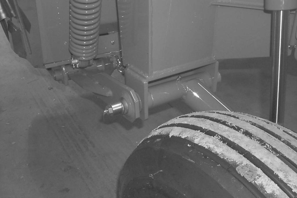
16 CHAPTER 5 CONTROLS & SAFETY EQUIPMENT The Disc Mower Conditioner is provided with several features for operator safety and convenience. WARNING BEFORE operating this equipment, become familiar with ALL safety devices and controls. Know how to STOP the Disc Mower Conditioner operation BEFORE starting it. DRAWBAR HITCH POSITIONING Transport Lock Valve in Open position Fig. WARNING BEFORE transporting the mower conditioner on a public highway, BE SURE to lock the positioner cylinder in the transport position with the transport lock valve. Repositioning the Disc Mower Conditioner tongue between the Transport and operating positions can be accomplished hydraulically. Hydraulic Hitch Positioner (Figs. & 2) The Disc Mower Conditioner is equipped with a hydraulic hitch positioner for remotely (from the tractor seat) relocating the drawbar from the centered Transport position to the various field operation positions. The hydraulic hitch positioner contains a double-acting hydraulic cylinder, hoses and a transport lock valve. When the Disc Mower Conditioner is in use in the field, the transport lock valve should be in the open position. When the Disc Mower Conditioner is centered behind the tractor in the transport position, the transport lock valve MUST be in the Transport position. Keep transport lock valve in the Transport position only during transport of the unit. Transport Lock Valve in Transport position Fig. 2 GUARDS & SHIELDS (Figs. 3 & 4) Whenever and wherever possible and without affecting machine operation, guards and shields have been used on this equipment to protect potentially hazardous areas. In many places, decals are also provided to warn of potential hazards as well as to display special operating procedures. WARNING Read and observe ALL warnings on the unit BEFORE operating it. DO NOT operate this equipment unless ALL guards and shields are properly secured in place /BP Printed in U.S.A.

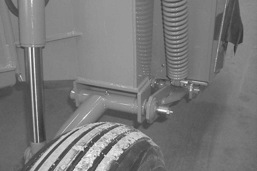
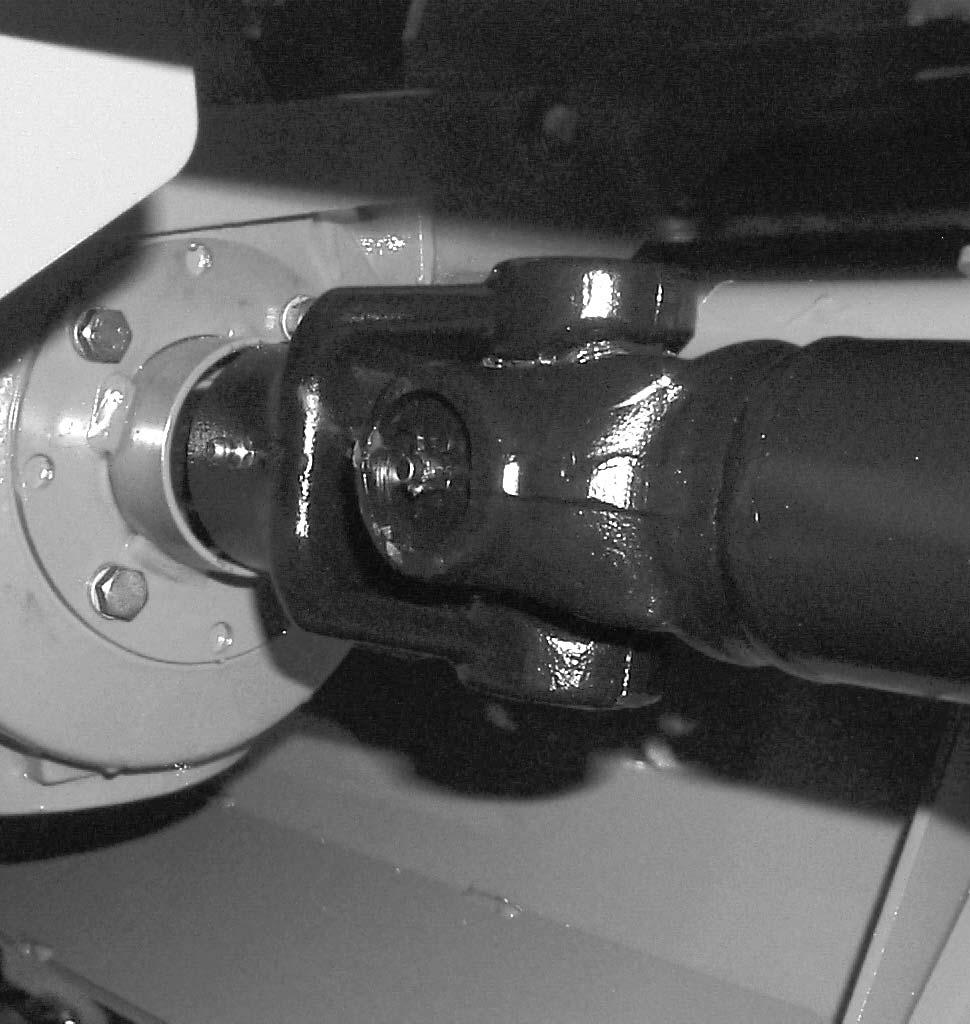
17 Chapter 5 Controls & Safety Equipment Implement Drive Line Shields The front telescoping PTO drive, between the PTO Tower and tractor PTO shaft, and the rear telescoping PTO drive, between the center PTO tower and gearbox, are equipped with rotating shields. The center driveline shield is stationary. 3 2 WARNING BE SURE that the rotating shields on the drives turn freely BEFORE starting the tractor engine. BE SURE any damaged or worn guard, shield, curtain or cover is replaced BEFORE operating the disc mower conditioner. 5 5 Rear Telescoping Drive Rotating Shield 2 Rear Steering Shield 3 Right Cover Assembly 4 Left Cover Assembly 5 Curtains Fig WARNING BEFORE performing any work on the disc mower conditioner, and BEFORE removing any guards or opening any covers or shields, BE SURE to exercise the MANDATORY SAFETY SHUTDOWN PROCEDURE (page 8). Also, BE SURE to replace ALL guards, shields and covers BEFORE operating the unit. Telescoping Drive Locking Coupler 2 Telescoping PTO Drive Shields 3 Jack Storage Hub (not on 2-Point Hitch units) 4 Hitchjack in Supporting Position (not on 2-Point Hitch units) 5 Center Drive Stationary Shield Fig. 3 Miscellaneous Guards Various latched and hinged guards, shields, curtains and covers are provided on the Disc Mower Conditioner to enable access for lubrication, service and adjustment. HITCHJACK (Fig. 4) On tractor drawbar attaching models, a hitchjack is furnished with the Disc Mower Conditioner to support the machine when the tractor is disconnected as well as to facilitate aligning the hitch with the tractor drawbar for hookup. When the jack is NOT being used to support the Disc Mower Conditioner, it can be removed and relocated to a storage position on the conditioner tongue. WARNING BE SURE the locking pin is properly seated into the holes through the jack tube and the Support Position hub on the drawbar BEFORE disconnecting the mower conditioner from the tractor. Printed in U.S.A /BP0603
 The Disc Mower Conditioner uses a remotely controlled (from the tractor seat) single-acting hydraulic cylinder master-slave system, to raise and lower the header.")
 Right Header Lift Transport Lock (Engaged) Fig.")
18 Chapter 5 Controls & Safety Equipment HEADER LIFT SYSTEM (Fig. 5) The Disc Mower Conditioner uses a remotely controlled (from the tractor seat) single-acting hydraulic cylinder master-slave system, to raise and lower the header. Before transporting the unit, BE SURE to raise the unit as high as possible and activate the transport lock valves on each side of the unit Locking Hitch Pin 2 Clevis 3 Drawbar Chain Loop 4 Locking Chain Hook Fig. 6: Accessory Safety Chain (Installed) Right Header Lift Transport Lock (Engaged) Fig. 5 WARNING BEFORE transporting the disc mower conditioner, raise the unit as high as possible and engage both transport lock valves. SAFETY CHAIN (Fig. 6) WARNING ALWAYS follow state and local regulations regarding a safety chain (NOT an elastic or nylon/plastic tow strap) when towing farm equipment on public highways! A safety chain should always be used, to retain the connection between the towing and towed machine, in the event of separation of the primary attaching system. BE SURE to check with local law enforcement agencies for your own particular regulations. As required or when desired, the Disc Mower Conditioner should be equipped with a safety chain for transporting the unit on public highways. A sturdy chain loop is welded to the side of the drawbar to facilitate anchoring the chain. Refer to the Optional Equipment & Accessories chapter for ordering information. TRANSPORT LIGHTS (Fig. 7) The Disc Mower Conditioner is equipped with transport lights as standard equipment. For your safety and the safety of others, it is recommended that you use the transport lights when traveling on public roadways. If your tractor is not equipped with a seven-prong auxiliary lighting receptacle, see your tractor dealer for installation of the required wiring. For additional information and regulations on transport lighting, check with your local law enforcement agency or your GEHL dealer. Transport Lights Fig /BP Printed in U.S.A.
19 Chapter 5 Controls & Safety Equipment TELESCOPING DRIVE COUPLER (Fig. 4) The front telescoping drive is equipped with a springloaded locking device to positively lock it onto the tractor PTO shaft. The locking device stays depressed against spring tension when the PTO is not attached to the tractor. Slide the yoke onto the tractor PTO shaft releasing the locking device. Move the yoke ahead or back until the lock engages into the groove of the PTO shaft. When towing the Disc Mower Conditioner behind a vehicle that does not have a PTO drive shaft to secure the front drive line to, the drive Line MUST be removed from the Disc Mower Conditioner. DO NOT move Disc Mower Conditioner with the front drive line setting on drive line storage prop. WARNING BE SURE that the telescoping PTO coupler is properly secured to the tractor PTO shaft and unit tower shaft BEFORE starting the tractor engine. TRANSPORT LOCK VALVES (Figs., 2 & 5) When the Disc Mower Conditioner is to be transported on a public highway, BE SURE to raise the unit all the way up and actuate both right and left header lift system transport lock valves. BE SURE to also swing the drawbar to the centered transport position and place the transport lock valve in the Transport position. Printed in U.S.A /BP0603
20 CAUTION BEFORE starting the tractor engine and running the disc mower conditioner for the first time, review and comply with ALL safety recommendations set forth in the SAFETY chapter of this manual. EMERGENCY SHUTDOWN In an emergency or in case a foreign object enters the header area, STOP cutting material IMMEDIATELY by disengaging the tractor PTO. Then, exercise the MANDA- TORY SAFETY SHUTDOWN PROCEDURE (page 8) BEFORE leaving the tractor seat to remedy the problem. WARNING BE SURE ALL factory installed guards and shields are properly secured in place BEFORE starting the tractor engine. BE SURE that NO people are within 00 feet (30 m) of the unit when engaging the PTO. Never operate with curtain in raised position. Do NOT engage PTO unless unit is in the working position. START-UP To avoid unnecessary strain on the Disc Mower Conditioner drive line components, ALWAYS engage the tractor PTO slowly with the tractor engine at less than half throttle. Bring the unit to PTO speed BEFORE starting to cut. Always operate at PTO speed! Attempting to operate at higher than PTO speed could cause excessive vibration, wear and early component failure. In addition, operating the unit at slower than PTO speed will cause poor windrow formation and increase the chances of plugging. GROUND SPEED The Disc Mower Conditioner can be operated in a wide range of ground speeds depending on crop conditions and/or terrain. Any change in ground speed should be made by changing tractor gears and NOT by increasing or decreasing tractor engine RPM. Slow down when turning or traveling over rough ground. CHAPTER 6 OPERATION UNPLUGGING It is possible for the Disc Mower Conditioner to plug in two different areas. It can become plugged in the disc area slipping the drive line clutch, or the unit can become wrapped in the conditioner rotor causing the belt to slip or the drive line clutch to slip. Plugged Discs To clear a plugging condition in the area of the discs:. Shut off the PTO. 2. Raise the header all the way up. 3. Exercise the MANDATORY SAFETY SHUTDOWN PROCEDURE (page 8). 4. Actuate both header transport lock valves. 5. Carefully clear the plug from the cutterbar area. 6. If the plugging occurs frequently, refer to the Troubleshooting chapter for additional directives. Wrapped Conditioning Rotor To clear wrapping from the Conditioning Rotor, proceed as follows:. Raise the unit fully. 2. Exercise the MANDATORY SAFETY SHUTDOWN PROCEDURE (page 8). 3. Actuate both header transport lock valves. 4. Open front covers on the header and remove excess material from the rotor by cutting with a suitable device. 5. Clear all crop from in front of the rotor. Be sure that no foreign objects are in front of the cutterbar or the rotor. IMPORTANT: MAKE SURE to close covers before resuming cutting. Tongue will damage covers unless closed. 6. If the plugging occurs frequently, use this manual as a guide to check the following. (See the Troubleshooting chapter for additional information.): Tractor speed Condition of cutterbar knives. Position of the conditioning hood. Conditioner belt tension Swathboard and windrow sheet adjustment. STARTING THE FIELD After the field has been checked and is known to be free of obstructions, it can be opened by cutting the first swath in either direction. However, it is recommended to make two or three rounds first to expose any potential hazards around the edge of the field. Then, to cut and condition the backswaths by operating in an opposite direction around the field /BP Printed in U.S.A.
21 Chapter 6 Operation STEERING Steering the DC252 is controlled by the tractor remote hydraulic system and allows the Mower Conditioner to follow directly behind the tractor, or make a full cut to either side, or an infinite number of positions in between. WARNING Do not activate steering system without being sure no person or object will be hit as frame and header move. The hydraulic hoses should be connected to the tractor so that by moving the tractor control lever forward, the Mower Conditioner steers right; by reversing the lever, the Mower Conditioner steers left. The controls are operated momentarily for steering and must be returned to OFF or NEUTRAL position as soon as the Conditioner reaches the desired path of travel. The second control lever, when moved back, lifts the header from the cutting position and when moved forward, lowers the header. The center pivot provides the operator the opportunity to move the Mower Conditioner into field position easily, allowing right angle turns in either direction, steering around objects on both sides, and straight line field cutting on either side of tractor, as shown in Fig. 8. Fig. 8 Printed in U.S.A /BP0603
22 Chapter 6 Operation 80 Degree Turnaround When it is desired to cut back and forth on one side of the field, approximately 4 to 6 cutting widths are required on each end of the field to make a 80 degree turnaround. The turn is accomplished as follows: Beginning at Position in Fig. 9, the tractor is guided away from the uncut crop while the Disc Mower Conditioner is guided straight ahead until cutting through the end. As soon as the discs cut through, raise the header to lift the skid shoes clear of the cut crop and then begin to steer the Disc Mower Conditioner to the direction away from the uncut crop. At Position 2, the Fig. 9: 80 Degree Turnaround tractor is guided back towards the uncut crop. In turning, MAKE SURE that the inside tractor tire does not contact the tongue of the Disc Mower Conditioner. In Positions 3 and 4, continue the turn towards the uncut crop with the Disc Mower Conditioner steered towards the outside of the circle, being aware of the tongue and tire caution, At Position 5, the tractor has completed the circle and the front wheels are turned to line up with the last cut windrow to straddle it. At this point, the Disc Mower Conditioner direction should be changed to line up with the edge of the uncut crop. Also, be prepared to lower the header to cutting height /BP Printed in U.S.A.
23 Chapter 6 Operation Disc Mower Conditioner to the extreme direction away from the uncut crop. As the tractor passes the corner, steer it sharply back towards the corner, but MAKE SURE that the inside tractor tire does not contact the tongue. Guide the tractor to straddle the last cut windrow. As the Disc Mower Conditioner completes its turning, be ready to steer it towards the uncut crop and align the header with edge of the uncut crop. OVERLOAD PROTECTION (Fig. ) The Disc Mower Conditioner is protected with a slip clutch on the main driveline to protect the cutterbar and the impeller. Fig. 0: Turning Square Corner Turning Square Corners The following procedure and diagram shown in Fig. 0 are intended only as a guide to aid the operator in setting up a turning procedure for the particular tractor being used. Distances are not specified due to the variations in tractor maneuverability. As the tractor approaches the corner, guide the tractor sharply away from the crop. The header is steered to maintain a straight cut ahead as the tractor moves away from the crop. As soon as the header cuts past where the new corner will be, steer the Main Driveline Slip Clutch (Steering Plate Removed) Fig. Printed in U.S.A /BP0603
24 CHAPTER 7 ADJUSTMENTS WARNING BEFORE performing any adjustments on this unit, exercise the MANDATORY SAFETY SHUTDOWN PROCEDURE (page 8). 2 The DC252 Disc Mower Conditioner has been designed and factory adjusted to function properly under most field operating conditions. However, due to the wide range of operating conditions encountered, some additional adjustments may be required. 3 WARNING BEFORE adjusting the cutting height, exercise the MANDATORY SAFETY SHUTDOWN PROCEDURE (page 8). HEADER FLOTATION (Fig. 2) NOTE: BE SURE to place the header in the operating position before adjusting the flotation. The header flotation is adjusted by varying the setting of the flotation spring on each end of the header. Lower the header to the operating position, loosen the jam nuts and tighten or loosen the spring bolts to achieve the desired flotation. In rocky or rough conditions, the flotation should be set lighter to protect the cutterbar. At higher mowing speeds, heavier settings follow terrain better. The flotation should be set as light as possible but heavy enough to follow the ground. IMPORTANT: Any change of cutting height or drawbar height will change the header flotation. BE SURE to readjust the flotation, if necessary, to avoid damage. Spring Adjustment Bolt 2 Jam Nut 3 Flotation Spring Fig. 2 CUTTING HEIGHT (Fig. 3) The cutting height can be adjusted from 3/4 (9 mm) to 3-/2 (89 mm) using the disc angle adjustment. NOTE: Any change to the cutting height requires that the flotation be checked and readjusted, as necessary. DISC ANGLE (Figs. 3 & 4) The disc angle is adjustable from 0 (3-/2, 89 mm cutting height) to 8 down (3/4, 9 mm cutting height). In rocky or rough conditions, use a flatter or 0 disc angle to protect the disc blades. In down, tangled and lodged crops, use a steeper or 8 disc angle to obtain a clean cut. To change the disc angle, it is necessary to move the rear pivot of the top link rearward (0 ) or forward (8 ). To prepare to adjust the Disc angle, raise the unit to the transport height, engage the transport lock valves but do NOT remove hydraulic pressure from the system /BP Printed in U.S.A.
25 Chapter 7 Adjustments WARNING Exercise the MANDATORY SAFETY SHUT- DOWN PROCEDURE (page 8) BEFORE adjusting the disc angle. 2 Cutterbar Tilt Cylinder 2 Adjusting Clevis Pin Fig. 3 To change the disc angle, place the clevis pin in the desired height location shown in Figure 4. The pin acts as a downstop when hydraulic pressure is removed from the unit to change from transport to operating position. Applying lift system pressure will raise the Cutterbar to the highest position before raising the conditioner. IMPORTANT: A disc angle change will change the header flotation. To avoid damage, BE SURE to readjust the header flotation after changing the disc angle. IMPORTANT: DO NOT place adjusting clevis pin in a hole behind the sliding plates when the header is tilted forward or damage may occur. SKID SHOES The skid shoes are located on the underside of the cutterbar frame and are NOT adjustable. 2 Position for 3/4 (9 mm) Cutting Height 2 Position 0 for 3-/2 (89 mm) Cutting Height Fig. 4: Each number represents approximately 0.3 (7.62 mm) of cutting height adjustment. Plate viewed from left side. Printed in U.S.A /BP0603
26 Chapter 7 Adjustments CONDITIONER ROTOR SPEED (Fig. 5) Conditioning occurs as plants scrape together when accelerating through the conditioning hood. This disturbs the waxy outer layer of the plant stem and speeds up moisture evaporation. Conditioning intensity can be adjusted by changing the rotor speed. Two rotor speeds are available (850 or 200 rpm) depending on the position of the drive sheaves and 2. The machine is delivered from the factory on high speed: Small sheave on the rotor and the large sheave on the input drive shaft. High Speed (000 rpm) Ideal for most crops. Low Speed (850 rpm) Ideal for tender crops or if leaf loss occurs at high speed. To change rotor speed:. Remove rotor drive belt by loosening idler spring until rotor belt can be removed. NOTE: It may be necessary to remove a sheave in order to remove the belt. NOTE: The input drive shaft requires two shim washers to properly clamp the sheave. Position the washers on either side of the sheave to properly align the drive sheave with the rotor sheave. 2. Remove cap screws, washers and sheaves and Install sheave removed from the rotor on the input drive shaft. Install sheave removed from the input drive shaft on the rotor. Install washers and cap screws. Tighten cap screws. 4. Install conditioner drive belt and tighten idler spring tension adjustment Nut 3 until the spring length equals 3-/2 (89 mm). 5. Tighten Jam Nut 4 securely. CONDITIONER ROTOR BELT TENSION (Fig. 5) Conditioner rotor belt tension should be checked weekly and adjusted if necessary. When properly adjusted, the spring length should be 3-/2 (89 mm).. Loosen jam nut Turn idler spring tension adjustment nut 3 until the spring length equals 3-/2 (89 mm). 3. Tighten jam nut 4 securely. 5 Large Rotor Drive Sheave 2 Small Rotor Drive Sheave 3 Idler Spring Tension Adjustment Nut [Properly Adjusted Spring Length should be 3-/2 (89 mm)] 4 Jam Nut 5 Input Drive Shaft Fig /BP Printed in U.S.A.

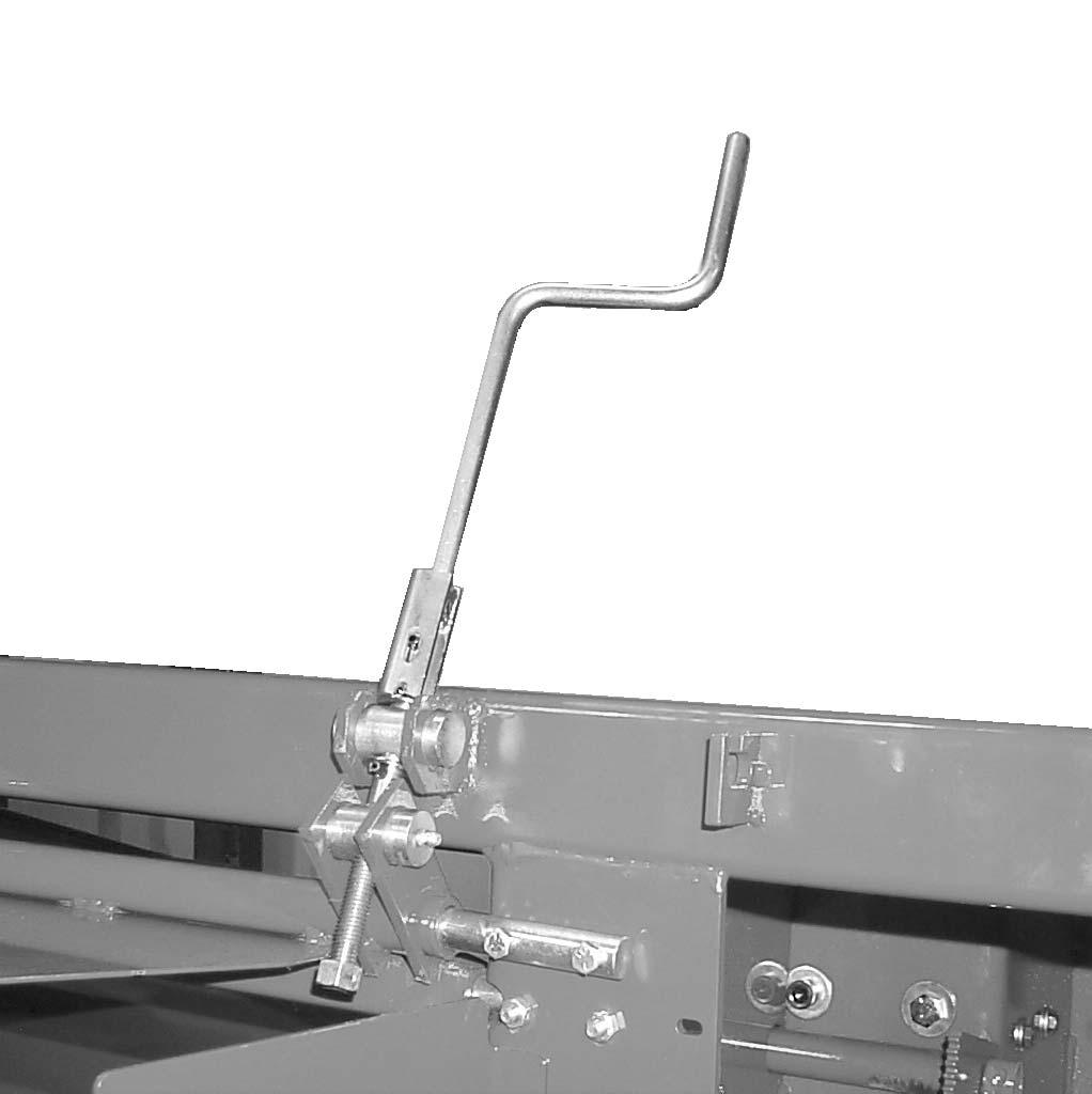
27 Chapter 7 Adjustments CONDITIONING HOOD ADJUSTMENT (Fig. 6) A hood is used above the flail conditioner to control, condition and direct the crop toward the rear of the unit. In light crop conditions, the hood can be moved closer to the rotor conditioner to make sure that the flails are making contact with the crop stems. The hood position is controlled with a single lever on the right side of the header behind the access door. Lower the lever to lower the hood. When the hood is lowered to the lowest position, maximum crop conditioning will occur. Raise the lever to raise the hood for minimum crop conditioning. 2 Conditioning Hood Adjustment Lever Fig. 6 Deflector Adjustment Hand Crank (Locked Position) 2 Deflector Adjustment Hand Crank (Adjusting Position) Fig. 7 WINDROW TO SWATH ADJUSTMENT (Figs. 7 & 8) The Disc Mower Conditioner will make anything from a narrow windrow to a wide swath, by moving the adjustable deflector up or down. The deflector can be adjusted using the deflector adjustment hand crank. In order to raise the deflector for a narrow windrow, turn the crank clockwise. In order to lower the deflector for a wide swath, turn the crank counterclockwise. Maximum swath width achievable is 00 (2540 mm). Fine tune windrow width setting by adjusting forming chamber sides. Narrow windrow width is 37 (940 mm). Forming Chamber Side Adjustment Fig. 8 Printed in U.S.A /BP0603
28 GENERAL INFORMATION WARNING NEVER lubricate the machine when any part of the unit is in motion. ALWAYS BE SURE to exercise the MANDATORY SAFETY SHUT- DOWN PROCEDURE (page 8), BEFORE lubricating the machine. A sufficient amount of oil or grease will prevent excessive part wear and early failure. IMPORTANT: Whenever service is performed on hydraulic components (valves, cylinders, hoses, etc.) or Transmissions, care must be taken to prevent discharging fluid onto the ground. Catch and dispose of fluid per local waste disposal regulations. CUTTERBAR (Fig. 9) IMPORTANT: The oil in the Cutterbar MUST be changed after the first 0 hours of operation. It is difficult to accurately check the oil in the cutterbar. If in doubt as to the amount of oil contained in cutterbar, do NOT add oil. Instead, drain and refill the cutterbar. The oil should be changed every 200 hours or at least annually (more often if operated under heavy loads). The cutterbar MUST be drained completely so that the exact volume of oil required can be put back into the cutterbar. The following procedure MUST be followed:. Operate the Disc Mower Conditioner for 0 minutes so that the Cutterbar reaches operating temperature. 2. Raise the Disc Mower Conditioner to the transport position and engage the transport lock valves. CHAPTER 8 LUBRICATION 3. Park the Disc Mower Conditioner so that the left rear corner of the cutterbar is the lowest point on the cutterbar. 4. Exercise the MANDATORY SAFETY SHUT- DOWN PROCEDURE (page 8). 5. Remove the skid shoe from the left end of the Cutterbar. Remove the drain plug from the bottom of the cutterbar and the filler plug located on top, rear of the cutterbar. See Fig. 9. Allow the oil to drain completely. Wait for the dripping to stop. 6. Reinstall the Drain Plug and the Skid Shoe. Refill Cutterbar with 5.25 pt (2.5 L) of SAE #80W90EP gear lube. The cutterbar should be checked daily for oil drips and dust accumulation around the seals. Oil drips or dust accumulation indicate that the seals are leaking. Oil which is tan in color and foams excessively indicates that it has water present. Cutterbar Drain Plug 2 Cutterbar Fill Plug Fig /BP Printed in U.S.A.
 The Disc Mower Conditioner must be down (in a cutting position) before oil levels are checked. Level plugs are provided for checking the oil level in the gearboxes.")
. The gearboxes use SAE #80W90EP Gear Lube. Cutterbar Gearbox.......... 34 oz. (.00 L) Top Header Gearbox.")

29 Chapter 8 Lubrication GEARBOXES (3, or 5 with 2-Point Swivel Hitch option) Check Daily (Figs. 20, 2, 22, 23 & 24) The Disc Mower Conditioner must be down (in a cutting position) before oil levels are checked. Level plugs are provided for checking the oil level in the gearboxes. The correct oil level range is when the oil is up to the level plug with the header down and rotated level (all the way back). The oil should be changed every 200 hours of operation or annually (more often if operated under heavy loads). The gearboxes use SAE #80W90EP Gear Lube. Cutterbar Gearbox oz. (.00 L) Top Header Gearbox oz. (0.85 L) Bottom Header Gearbox oz. (2.60 L) Swivel Hitch Top Gearbox.. 37 oz. (. L) Swivel Hitch Bottom Gearbox 56 oz. (.7 L) Cutterbar Gearbox The cutterbar gearbox is located on the right hand side of the unit under the right hand cover. The breather/fill plug is accessible without removing the cover. To gain access to the drain plug, two bolts, lock washers and the cover must be removed. The level plug is accessible by opening the right hand hinged access panel. WARNING DO NOT operate with the cutterbar gearbox cover removed. Crop will wrap around the gearbox shaft and damage the oil seal resulting in cutterbar gearbox failure Drain Plug 2 Breather/Fill 3 Level Plug 4 Cutterbar Gearbox Cover Fig. 20: Cutterbar Gearbox Printed in U.S.A /BP0603


30 Chapter 8 Lubrication Bottom Header Gearbox The bottom header gearbox is located in the middle of the unit under the right hand cover. The fill plug is located on the top, rear corner of the bottom header gearbox. The proper oil level will be approximately half way up the lower portion of the elbow as shown. Top Header Gearbox The top header gearbox is located in the middle of the unit. The breather/fill plug, drain plug and level plug are located on the rear of the upper header gearbox. 2 2 Breather/Fill 2 Level Plug 3 Drain Plug Fig. 22: Top Header Gearbox 3 Top and Bottom Hitch Gearboxes The top and bottom hitch gearboxes are located on the front of the tongue. The breather/fill plug, drain plug and level plug are located on the rear of the bottom gearbox and on the front of the top gearbox Drain Plug 2 Plug/Fill 3 Oil Fill Level in Elbow Fig. 2: Bottom Header Gearbox Breather/Fill 2 Level 3 Drain Fig. 23: Top Hitch Gearbox 90987/BP Printed in U.S.A.

31 Chapter 8 Lubrication 2 Wipe dirt from the fittings before greasing to prevent any dirt from being forced into the bearings or pivots. Replace any missing fittings. To minimize dirt build-up, avoid excessive greasing. NOTE: In addition to the fittings, inspect and repack the wheel bearings at least once a season. Grease Fitting Locations Breather/Fill 2 Level 3 Drain Fig. 24: Bottom Hitch Gearbox The gearboxes should be checked occasionally for oil drips and dust accumulation around the seals. Oil drips or dust accumulation indicate that the Seals are leaking. Oil which is tan in color and foams excessively indicates that it has water present. NOTE: The oil in the gearboxes MUST be changed after the first 0 hours of operation. SEALED BEARINGS Sealed bearings are used throughout the machine to provide trouble-free operation, with a minimum of maintenance and lubrication. These sealed bearings are lubricated for life and re-lubrication is NOT required, NOR should it be attempted. GREASING IMPORTANT: Grease all fittings at the intervals of operation listed, before and after storing the unit, and as otherwise listed. Use a good grade of lithium base grease. 3 Grease Every 0 hours (or Daily). Telescoping PTO Drive Crosses (as many as Places) 2. Telescoping PTO Drive Tube (2 Places) 3. Overrunning Clutch ( Place) 4. Inner Left Pusharm (2 Places) 5. Inner Right Pusharm (2 Places) 6. Right and Left Wheel Leg Pivots (2 Places) 7. Cutterbar U-joints and spline (3 Places) Grease Every 50 hours (or Weekly) 8. Hitch Center Pivot ( Place) 9. Cross Shaft Spline and Cross (5 Places) 0. Conditioning Hood Pivots (3 Places). Swath Board Adjustment Threads 2. Swivel Gearbox Hitch Pivot ( Place) (2-point hitch only) NOTE: To grease the rear telescoping drive Tube (Step 2.), swing the header fully left or right and locate the hole in the inner shield tube. Align the hole with the slot in the outer tube and swing the header until the slot and hole are aligned. Rotate the driveline by hand until the grease fitting lines up with the hole. Printed in U.S.A /BP0603


32 Chapter 8 Lubrication /BP Printed in U.S.A.
33 CHAPTER 9 SERVICE GENERAL INFORMATION WARNING BEFORE servicing this unit, exercise the MANDATORY SAFETY SHUTDOWN PROCE- DURE (page 8). NOTE: The following information is also referred to in the Troubleshooting chapter of this manual. It should be understood that all services detailed in this chapter are owner-operator responsibilities. Certain service routines, where indicated, should only be performed by (or under the direction of) an authorized GEHL equipment dealer. SEALED BALL BEARING REPLACEMENT (Fig. 25) Sealed ball bearings are used on various shafts, around the unit. This type of bearing is generally retained, in place, with a self-locking eccentric collar. The lock collar has a counter bored recess, which is eccentric with the collar bore. This eccentric recess engages or mates with an eccentric end of the bearing inner ring, when the bearing is assembled on the shaft. The bearing is engaged, on the inner ring cam, by the collar. This assembly grips the shaft tightly with a positive binding action that increases with use. The collar set screw provides supplementary locking. A bearing can be removed from the shaft by unscrewing the set screw, placing a punch in the drift pin hole in the direction opposite shaft rotation, and tapping on the punch in order to loosen the self-locking collar. Install bearings with self-locking collars in the following manner:. Place the bearing and collar on the shaft with the cam surfaces next to each other. Tighten the bolts on the bearing retainers. 2. Mate the cam of the lock collar with the cam of the bearing inner ring. 3. Press the locking collar against the bearing wide inner ring and turn it, in the direction of shaft rotation, until it tightly engages. Tighten the collar further by tapping on a punch inserted in the drift pin hole. IMPORTANT: Overtightening the collar may result in damage. 4. Last, tighten the set screw in the locking collar. A C E A Bearing B Set Screw C Collar Cam D Wide Inner Cam Ring E Drift Pin Hole F Eccentric Self Locking Collar Fig. 25 B D F Printed in U.S.A /BP0603
34 Chapter 9 Service CONDITIONER Rotor Belt Tension (Fig. 26) The conditioner rotor belt idler tension is controlled by an adjustable idler spring. The properly adjusted spring length should be 3-/2 (89 mm).. Loosen jam nut. 2. Adjust idler spring tension adjustment nut until proper spring length is attained. 3. Tighten jam nut securely. Rotor Belt Replacement (Fig. 26). Loosen idler spring tension until rotor belt can be removed. NOTE: It may be necessary to remove the rotor drive sheave in order to remove the belt. 2. Install new conditioner drive belt and tighten idler spring tension adjustment Nut 3 until the spring length equals 3-/2 (89 mm). 3. Tighten Jam Nut 4 securely. 5 Large Rotor Drive Sheave 2 Small Rotor Drive Sheave 3 Idler Spring Tension Adjustment Nut [Properly Adjusted Spring Length should be 3-/2 (89 mm)] 4 Jam Nut 5 Input Drive Shaft Fig. 26 SHEAVE ALIGNMENT 2 The sheaves are aligned at the factory and should NOT need adjustment. If sheaves are not properly aligned, contact your Gehl dealer for proper instructions. 4 3 CUTTERBAR All service to the internal parts of the cutterbar MUST be performed by (or under the direction of) an authorized GEHL equipment dealer. The disc bearing housing assemblies are serviceable as complete units or select individual components. Should this be required, contact your Gehl dealer. DISCS, KNIVES AND HARDWARE Discs, knives, bolts and nuts are fabricated from high quality steel and undergo a special heat treatment process to ensure a tough wear resistance and hence a longer life. To avoid creating hazardous out-of-balance forces, ALWAYS replace missing, damaged or worn knives and hardware in pairs! IMPORTANT: Worn or damaged items MUST be replaced immediately with genuine GEHL service parts, otherwise the warranty is void. Cutterbar Inspection The cutterbar should be inspected for damage or wear on a regular basis, such as when turning or replacing knives. Inspect the cutterbar more frequently when operating in known rocky conditions.. Inspect the external components for damage paying particular attention to the knives and discs. Broken knives and bent or cracked discs are a result of contact with solid foreign objects, and may indicate a possible internal damage. A disc out of time may also indicate internal damage; the discs are properly timed when they are positioned 90 to each other. WARNING The bottom leading edge of worn discs can become very sharp. Wear gloves to prevent injury. 2. While wearing protective gloves, carefully grab both ends of each disc, and try to rock the disc up and down. A small amount of movement is normal. An excessive amount of movement may be the result of a loose spindle nut or could indicate a worn housing or bearings. Disc spindles with excessive disc rock should have the disc and spindle nut checked for proper torque /BP Printed in U.S.A.
35 Chapter 9 Service Knife Hardware (Fig. 27) If any of the following conditions exist, the knife retaining hardware MUST be replaced. See Fig. 27 for details.. When a visible deformation is found. 2. When the locking compound on the bolt threads has worn away or if the locking compound has become inoperative due to contamination by water, oil or dirt. 3. When wear on the bolt head reaches the contact area of the knife. 4. When a wear groove deeper than /8 (3 mm) has formed on the bearing shoulder of the knife bolt. 5. When wear on the nut reaches a depth equal to half the height of the nut. 2. The width of a knife, measured at a distance of 3/8 (0 mm) away from the edge of the disc, MUST be greater than 3/4 of the original width of the knife. (Fig. 28) 3. The hole in knife for retaining bolt MUST NOT become worn oval by more than /6 (2 mm). 6. When the retaining hardware has been removed five times. A 3/8 (0 mm) B MUST Be Greater Than 3/4 Width of Knife Here C Maximum Out-of-Round /6 (2 mm) Fig. 28 Acceptable Bolt with Locking Compound Intact 2 Unacceptable Bolt with Wear Groove 3 Unacceptable Bolt with Edge Wear 4 Acceptable Nut 5 Unacceptable Nut with Edge Wear Fig. 27 Removal & Replacement of Blades (Fig. 28) Knives should be inspected systematically each time before the Disc Mower Conditioner is operated. Failure to replace knives as required will result in an increase in the risk of accidents, a deterioration in the quality of cut and a risk of damage to the cutterbar. both knives on each disc MUST be replaced in pairs to maintain balance if any of the following conditions exist (Fig. 28):. If any sign of cracking is found. When replacing knives on the Disc Mower Conditioner, the following steps MUST be followed:. Clean around each nut to be removed. 2. Place a block of wood between the discs so the discs will NOT rotate when removing the bolts. 3. Remove nuts with an 6-point, 3/4 socket. Position disc to allow blade bolt to drop through access hole in front center of skid shoe. 4. Clean the hole before installing new blade. 5. Fit new knives or turn knives to use second cutting edge. BE SURE that each knife is positioned with the small arrow pointing in the direction of rotation of the disc that the knife is to be fitted to. 6. MAKE SURE the bolt is in good condition BEFORE reusing. 7. Torque nuts to 90 ft-lbs. (22 N m). WARNING Use ONLY genuine GEHL service parts. Printed in U.S.A /BP0603
. Place a block of wood between the discs so the discs will NOT rotate when removing the bolts. 2.")
36 Chapter 9 Service NOTE: To ensure proper knife retention, the retaining hardware MUST be replaced after having been removed five times. WARNING ALWAYS replaces damaged knives in pairs. NEVER attempt to straighten a bent knife. Disc Removal & Replacement (Figs. 30 & 3). Place a block of wood between the discs so the discs will NOT rotate when removing the bolts. 2. Remove the bolts and flat washers. Disc Bearing Housing Removal and Replacement (Fig. 29) The gear, shaft, bearing, housing and hub that drive the discs are available as complete assemblies. The drive spindle assembly has a machined groove on the outside of the drive flange as shown. The non-drive spindle does not have any markings. When replacing components of these assemblies, make sure to apply Loctite 27 to the bottom spindle nut and torque the nut to 285 ft-lbs. (386 N m). When replacing an assembly, apply silicone sealant around bolts and housing and make sure to position the spindle properly to its adjacent spindles and apply Loctite to nuts and torque to 60 ft-lbs. (8 N m) in a cross-corner pattern. See Fig. 29. Bolt 2 Flat Washer Fig Drive Spindle 4 Machined Groove Non-Drive Shear Spindle 3 Complete Disc Bearing Housing Assembly 2 Self-locking Nut M0-.5, Torque 60 ft-lbs. (8 N m) 3 Bolt, M0-.5 X 25 mm 4 Align holes in spindle hubs exactly with adjacent holes along this centerline. Fig. 29 Disc Assembly ( mm) Clearance Fig Remove the disc. If the disc is tight, pry up with two levers at opposite sides of the disc. 4. Replace the disc MAKING SURE that it is rotated 90 from the next disc and that each blade is positioned with the small arrow pointing in the direction of rotation of the disc. Refer to the Service Parts Manual for the proper positioning of discs. Secure with the bolts and flat washers. Torque to 60 ft-lbs. (8 N m). NOTE: Disc assemblies must have a minimum clearance of.040 ( mm) between the bottom of the knife bolt and the top of the cutterbar and skid shoes. See Figure 3 for details /BP Printed in U.S.A.
37 Chapter 9 Service NOTE: If a disc shows signs of wear after a considerable amount of acreage has been cut, it is advisable to replace it. Contact your dealer s Service Department for assistance if the disc assembly-to-cutterbar clearance is less than specified. Extending Disc Life (Fig. 32) Under certain conditions, when mowing in abrasive soils, the disc can wear to the point of perforation. If unusual wear is detected prior to perforation as shown in Fig. 32, discs may be moved to a cutting station that rotates in an opposite direction. Proceed as follows:. Remove disc according to Disc Removal & Replacement topic of this chapter. Remove knives from disc. 2. Locate cutting station that rotates in opposite direction. 3. Install disc according to Disc Removal & Replacement topic of this chapter. Install new knives BEING SURE that each knife is positioned with the small arrow pointing in the direction of rotation. IMPORTANT: If the disc is worn to the point of perforation, the disc MUST be replaced. DO NOT make weld repairs to the discs, as this will affect disc strength and balance. HYDRAULIC TONGUE CYLINDER WARNING Do NOT remove hydraulic tongue control cylinder with conditioner header off the ground. The tongue can rotate and cause crush injury. HYDRAULIC LIFT CYLINDERS (Fig. 33) IMPORTANT: Whenever service is performed on hydraulic components (valves, cylinders, hoses, etc.), care must be taken to prevent discharging fluid onto the ground. Catch and dispose of fluid per local waste disposal regulations. The Disc Mower Conditioner lift system consists of a master-slave cylinder arrangement, as shown. With a master-slave set-up, the hydraulic oil, from the rod end of the master cylinder, goes into the base end of the slave cylinder. Because of this arrangement, both cylinders will extend equally, under any load. With a master-slave arrangement, the cylinders can become out-of-phas such that the machine will raise unevenly (left end higher or lower than the right end). Use the following steps to re-phase the lift cylinders:. Completely raise and lower the unit several times, keeping the tractor hydraulic lever engaged, until NO cylinder movement is observed. NOTE: The cylinders will move very slowly while equalizing. 2. If the unit is still unequal, proceed to step 3 or 4, depending on the problem. Direction of rotation 2 Wear shows up here 3 Perforation can occur here Fig. 32 Printed in U.S.A /BP0603
38 Chapter 9 Service WARNING BE SURE there is NO pressure in the lines when loosening the fittings. Hydraulic fluid, under pressure, can penetrate the skin. If injured by escaping fluid, see a doctor at once. Injected fluid MUST BE surgically removed by a doctor familiar with this type of injury or gangrene may result. 3. If the slave cylinder (right) will NOT raise fully, when the master cylinder (left) is fully raised, loosen the fitting into the slave cylinder (bleed point as shown). With the fitting loose, slowly raise the unit, until oil appears at the fitting. Then, re-tighten the fitting and repeat step. 4. If the master cylinder (left) will NOT raise fully, when the slave cylinder (right) is fully raised, loosen the fitting into the slave cylinder (bleed point as shown). With the fitting loose, remove approximately 4 oz (20 cc) of oil for every one inch (25 mm) of cylinder length difference. Then, re-tighten the fitting and repeat step. If the hydraulic cylinders become un-phased frequently during use, it will be necessary to replace the piston seals in the master cylinder. Only replace the slave gland seals if it is leaking externally. NOTE: A leaking tractor valve may cause one or both hydraulic cylinders to raise slowly while cutting. TELESCOPING DRIVES IMPORTANT: For safety reasons, service on the telescoping PTO Drives should ONLY be performed by (or under the direction of) an authorized GEHL equipment dealer. Over time, the telescoping drive universal joints may become worn and noisy and require service. As necessary, remove the drive(s) from the Disc Mower Conditioner and take them to your dealer. TIRES & WHEELS Tires should be inflated to 30 PSI (20 kpa). The wheel lug nuts should be torqued to 90 ft-lbs. (24 N m). The wheel bearings should be torqued to 8 ft-lbs. ( N m), while oscillating the wheel 90. Then, back off and retorque to 4 ft-lbs. (5 N m). The slotted nuts should be backed off one cotter pin slot. Check the tire pressures after every 50 hours of operation. Tires should be inflated to 30 PSI (20 kpa). Wheel lug torque should be checked after every 50 hours of operation and tightened to 90 ft lb (24 N m) torque. CAUTION Left Side 2 Master Cylinder 3 To Tractor 4 Bleed Point 5 Slave Cylinder 6 Right Side Fig. 33 Gehl Company does not sell replacement Tires. In addition, tire mounting, repair and replacements should ONLY be attempted by a qualified tire manufacturer s representative or by properly trained personnel following the tire manufacturer s instruction. If you do not have such instructions, contact your tire dealer or Gehl Company /BP Printed in U.S.A.
39 Chapter 9 Service WARNING Inflating or servicing tires can be dangerous. Whenever possible, trained personnel should be called to service and/or mount tires. In any event, to avoid possible death or serious injury, follow the safety precautions below: BE SURE the rim is clean and free of rust. Lubricate both the tire beads and rim flanges with a soap solution. Do NOT use oil or grease. Use a clip-on tire chuck with a remote hose and gauge which allows you to stand clear of the tire while inflating it. DO NOT place your fingers on the tire bead or rim during inflation. NEVER inflate beyond 35 PSI (240 kpa) to seat the beads. If the beads have NOT seated by the time the pressure reaches 35 PSI, deflate the assembly, reposition the tire on the rim, relubricate both parts and re-inflate it. Inflation pressure beyond 35 PSI with unseated beads may break the bead or rim with explosive force sufficient to cause death or serious injury. After seating the beads, adjust the inflation pressure to the recommended operating pressure listed. Do NOT weld, braze, or otherwise attempt to repair or use a damaged rim. Printed in U.S.A /BP0603
40 CHAPTER 0 PREPARING FOR FIELD OPERATION TRACTOR REQUIREMENTS The tractor used to operate a Disc Mower Conditioner, MUST have:. A minimum of 85 hp (64 kw) 2. A 000 RPM PTO matching the operating speed of the Disc Mower Conditioner. 3. PTO and hitch dimensions as shown. 4. Two remote hydraulic outputs capable of powering a double-acting cylinder. A minimum operating pressure of 800 PSI (2.4 MPa) is required to lift the Disc Mower Conditioner. 5. It is recommended that the towing tractor be equipped with an enclosed operator s cab with safety glass or polycarbonate windows, or with protective mesh screens. IMPORTANT: If this unit is connected to a tractor equipped with a clevis-style drawbar, the clevis parts shown in dashed lines MUST be removed to prevent damage to the unit driveline. See Fig. 34. Clevis Parts To Be Removed Fig /BP Printed in U.S.A.
 Adjust the tractor hitch to meet Dimension 5 in Figure 35.")
 throughout the full range of")
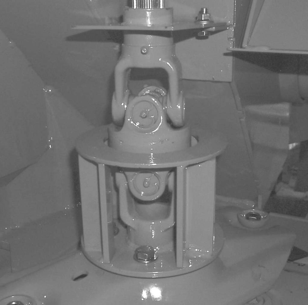
41 Chapter 0 Preparing For Field Operation ATTACHMENT TO TRACTOR IMPORTANT: Whenever the Disc Mower Conditioner is operated on a tractor other than the original tractor the unit was set up for, the drawbar height and header flotation must be checked and adjusted accordingly. Tractor Drawbar Requirements, 3-Point Hitch (Fig. 35) Adjust the tractor hitch to meet Dimension 5 in Figure 35. Position the drawbar left or right of center. Also adjust the tractor hitch turnbuckles so that the distance between universal cross centers on the tractor to implement PTO is between 23 to 33 inches (585 to 838 mm) throughout the full range of tractor hitch motion. IMPORTANT: DO NOT exceed the listed dimensions, or damage to the tractor and Disc Mower Conditioner will occur Mower Mounting Yoke 5 24 to 29 (60 to 737 mm) ground to center of PTO RPM PTO Input Shaft (or rear center of lower Transmission) height 3 Tractor with Category II or Category III, 3-point style hitch or quick hitch 6 Stabilizing Chain (one each side, optional) 4 Locking Hitch Pin (one each side, supplied) Fig. 35: Tractor with Category II 3-point Hitch Hitch Positions (Fig. 36) The Disc Mower Conditioner hitch can be set up to fit category II and category III 3-point and quick hitches. The Disc Mower Conditioner hitch mounting width is changed by exchanging the hitch brackets mounting positions. Hitch pin diameters are changed by adding or removing hitch bushings. Hitch bushings are stored in the toolbox when not in use. NOTE: The bolt pattern in the hitch and hitch brackets is such that the hitch brackets MUST be switched side-to-side, and not turned over. The hitch bracket is properly installed when the flared flanges face downwards. 2 Right Hitch Arm 2 Hitch Bracket 3 Locking Hitch Pin Fig Printed in U.S.A /BP0603
42 Chapter 0 Preparing For Field Operation Tractor Drawbar Requirements, Clevis Hitch (Fig. 37) Adjust the tractor drawbar to meet dimension No. 3 in Fig. 37 to avoid damage to the front telescoping PTO Drive. Adjust the drawbar left or right to place the hitch pin hole directly in line with the PTO Shaft. IMPORTANT: To prevent damage to the Disc Mower Conditioner telescoping drive, PTO tower and tractor PTO shaft, avoid making sharp turns. Tractor PTO Shaft (Tractor MUST comply with ASAE Standard S203). 2 6 to 2 (52 to 305 mm) [8 (203 mm) preferred] This is measured from the center of the tractor PTO shaft to the top of the tractor drawbar at the hitch pin hole. 3 6 (406 mm) for 000 RPM operation. This is measured from the end of the Tractor PTO Shaft to the center of the Hitch Pin /2 (845 mm) for 000 RPM operation. This is measured from the retaining groove in the Implement Input Drive Shaft to the center of the Implement Hitch Hole. 5 3 to 22 (330 to 560 mm) [8 to 20 (457 to 508 mm) preferred] This is measured from the top of the tractor drawbar at the hitch pin hole to level ground. 6 0 to 3 (0 to 76 mm) Tire Bumper Extension Kit NOT required; 3 to 6 (76 to 52 mm) optional Tire Bumper Extension Kit required (see Optional Equipment and Accessories chapter of this manual), 6 and above, DO NOT use tractor with this hitch as driveline damage will occur. Fig. 37: Clevis Hitch 90987/BP Printed in U.S.A.
43 Chapter 0 Preparing For Field Operation PTO Clean and lightly grease the splines on the tractor PTO shaft and the yoke of the telescoping drive. Depress the safety lock ring and slide the yoke onto the tractor PTO shaft. Move the yoke back and forth until the safety lock ring pops forward and locks into the groove in the PTO shaft. WARNING BE SURE that the PTO safety lock ring is positively engaged and that the tongue is securely connected to the tractor 3-point hitch with the supplied locking pins or to the tractor drawbar with a locking clip pin BEFORE starting the tractor engine. Also, BE SURE that the tractor PTO shield is in place and properly secured and that the telescoping drive shields rotate freely BEFORE starting the tractor engine. HYDRAULIC LIFT Install the supplied quick-disconnect fitting (to match your tractor connection) onto the lift cylinder hose (left hose). Make the lift cylinder hose attachment to the tractor, start the tractor and operate the valve to raise and lower the Disc Mower Conditioner several times to purge the air out of the system. IMPORTANT: If the Disc Mower Conditioner is NOT horizontal when it is being raised and lowered, refer to the Service chapter for corrective measures. STEERING AND LIFT CYLINDER HOOKUP (Fig. 38) The two hoses (2 right hoses) from the steering cylinder should be hooked up so that when the tractor control handle is moved to the forward position the header will move to the right. (Pressure from this line will retract the steering cylinder). Moving the control handle to the rearward position will move the header to the left. (Pressure on this line will extend the steering cylinder.) The lift cylinder hose should be connected to another valve so when the control handle is pulled to rear position the entire machine will raise. The operator may prefer to position the cylinder connections differently for more efficient use of the control handles during field operation. Remote Hydraulic Levers Typical Arrangement 2 Steer Right 3 Lower Entire Machine and Tilt Header Down 4 Right Hydraulic Lever 5 Steer Left 6 Tilt Header Up and Raise Entire Machine Fig. 38 WARNING Do NOT remove hydraulic tongue control cylinder with conditioner header off the ground. Failure to heed can result in death or serious injury. NOTE: Operation of the tongue control cylinder requires a tractor with two remote hydraulic outputs, one for the tongue control and another for the lift control. CUTTING HEIGHT & HEADER FLOTATION Adjust the cutting height and header flotation following information in the adjustments chapter of this manual. SAFETY CHAIN (Fig. 39) Only a safety chain (NOT an elastic or nylon/plastic tow strap) should be used to retain the connection between the towing and towed machines, in the event of separation of the primary attaching system. Refer to Optional Equipment & Accessories chapter for part number information. Printed in U.S.A /BP0603
44 Chapter 0 Preparing For Field Operation 2 Extension Hitch 2 Safety Chain & Clevis 3 Locking Hitch Pin 4 Welded-on Ring Fig. 39: Safety Chain (Installed) BREAK-IN Before starting to cut and condition, it is recommended that the Disc Mower Conditioner be broken-in by running it empty for approximately 20 minutes. This 4 3 initial run-in should be done with the header on the ground. Before running the unit however, perform the daily (0 hour) maintenance routines listed in the beginning of the Operation chapter. The break-in should consist of a five minute and a fifteen minute running period. First, run the unit for five minutes with the tractor engine close to idle RPM. Next, stop the unit and exercise the MANDATORY SAFETY SHUTDOWN PROCEDURE (page 8). Reinspect the unit. After inspection is complete, connect the PTO, start the tractor, engage the PTO near engine idle speed and gradually increase the speed to proper operating RPM and continue running the machine for 5 minutes. Stop the unit and exercise the MANDATORY SAFETY SHUTDOWN PROCEDURE (page 8) again. After another inspection, the Disc Mower Conditioner is ready for the field. IMPORTANT: The oil in the cutterbar and the gearboxes MUST be changed after the first 0 hours of operation. For details, see the Lubrication chapter of this manual. TRANSPORTING BEFORE transporting the Disc Mower Conditioner, refer to the Transporting chapter of this manual for additional transporting information /BP Printed in U.S.A.
 When the Disc Mower Conditioner is going to be transported on a public highway, BE SURE to raise the unit all the way up and actuate both lift system transport lock valves.")
45 CHAPTER TRANSPORTING TRANSPORT LOCK VALVES (Figs. 40, 4 & 42) When the Disc Mower Conditioner is going to be transported on a public highway, BE SURE to raise the unit all the way up and actuate both lift system transport lock valves. Also, BE SURE to swing the drawbar to the centered transport position with the hydraulic hitch positioner and position the transport lock valve on the drawbar in the transport ( closed ) position. 2 Red Reflector 2 Left Header Lift Cylinder Lock Engaged 3 SMV Emblem Mounting Bracket (Shown with SMV Emblem Removed) Fig. 40 Hydraulic Hitch Positioner Transport Lock Valve ( Closed ) Fig. 4 3 Transport Lock Valve in Open position Fig. 42 SAFETY CHAIN (Fig. 43) WARNING ALWAYS follow state and local regulations, regarding a safety chain (NOT an elastic or nylon/plastic tow strap) when towing farm equipment on public highways! A safety chain should always be used to retain the connection between the towing and towed machine, in the event of separation of the primary attaching system. BE SURE to check with local law enforcement agencies for the particular regulations. NEVER transport the disc mower conditioner at speeds greater than 25 mph (40 km/h). On units not equipped with the 2-point hitch, the Disc Mower Conditioner can be equipped with a safety chain for operation on public highways. A sturdy chain loop is welded to the side of the drawbar to facilitate anchoring the chain. The safety chain, when attached in this manner, has the following characteristics:. Chain is sufficiently slack to allow turns and movements of either the tractor or the farm implement, without placing tension on the chain. 2. Chain is of sufficient strength to hold the decoupled implement (and its load) and tow it to the shoulder. Printed in U.S.A /BP0603
 TRANSPORT LIGHTS (Fig.")
46 Chapter Transporting A GEHL Safety Chain, part number 42965, is available through your GEHL Dealer. is not equipped with the proper receptacle, see your tractor dealer for details Extension Hitch 2 Safety Chain and Clevis 3 Locking Hitch Pin 4 Welded-on Ring Fig. 43: Accessory Safety Chain (Installed) TRANSPORT LIGHTS (Fig. 44) Transport lights are provided as standard equipment on the Disc Mower Conditioner. The lights use a standard 7-pin connector to connect to the tractor. If your tractor Transport Lights Fig. 44 SMV EMBLEM AND REFLECTORS (Figs. 45 & 46) The Disc Mower Conditioner is provided with a slow-moving vehicle (SMV)emblem mounting bracket on the upper left back end of the conditioner frame. A slow-moving vehicle emblem, is standard. Red, orange and amber reflector strips are also provided at the rear corners of the conditioner frame /BP Printed in U.S.A.
47 Chapter Transporting Red Reflectors (2 Places) 2 Amber Reflectors (6 Places) 3 Orange Reflectors (2 Places) 4 SMV Emblem & Bracket (Standard Equipment) Fig. 45: SMV & Reflectors Red Reflectors (2 Places) 2 Amber Reflectors (6 Places) 3 Orange Reflectors (2 Places) 4 SMV Emblem & Bracket (Standard Equipment) Fig. 46: SMV & Reflectors Printed in U.S.A /BP0603

48 CHAPTER 2 STORAGE After the harvesting season, store the Disc Mower Conditioner in a dry place where it is not exposed to weather or livestock. BEFORE STORING Perform the following preparations on the Disc Mower Conditioner, before placing the unit into off-season storage:. Disc Mower Conditioner in transport position and transport locks valves in lock position. 2. Wash off the entire machine. Take special care to remove gum and accumulated dirt from the cutterbar. 3. Remove trash and debris which may be wrapped around shafts and/or lodged against bearings. 4. Repaint any areas where the paint has been worn off or brush motor oil on these areas. 5. Lubricate the entire machine following the information in the Lubrication chapter of this manual. BE SURE to change the gearboxes and cutterbar oils. Apply motor oil to adjusting bolt threads. 6. Apply grease to any exposed cylinder rods. 7. Take note of any damaged or missing parts or attaching hardware; order and replace them during the off-season. Replace any damaged curtains. 8. Check all hydraulic components, hoses and fittings for damage or leaks; make repairs or corrections, as required. 2. Remove any trash or debris which may have accumulated on the unit during storage. 3. Check and re-inflate the tires and re-torque the wheel lugs. 4. Readjust the flotation springs tension. 5. Inspect cutterbar knives. 6. Lubricate the entire machine following the information in the Lubrication chapter of this manual. 7. Check drive belt tension following the information in the Service chapter of this manual. 8. Perform the clutch run in procedure as outlined in the Steps below. 2 a. Remove one of the gearbox steering side plates. b. Loosen (but do NOT remove) the six clutch bolts (see Fig. 47). c. Place a block of wood between two cutterbar discs to prevent rotation. d. Rotate the driveline by hand until the clutch slips. e. Tighten the six clutch bolts. f. Install the removed gearbox steering side plate. AFTER STORING After taking the Disc Mower Conditioner out of storage and before the start of the harvesting season, carefully check the unit over and make the following inspections and preparations:. Replace all guards, shields and covers. Review and re-familiarize yourself with all safety precautions outlined in the Safety chapter of this manual. Clutch Bolt ( of 6) 2 Gearbox Steering Side Plate Fig /BP Printed in U.S.A.
R T SERIES ROTARY TILLER
 R T SERIES ROTARY TILLER Operating and Maintenance Manual TABLE OF CONTENTS 1. PRODUCT WARRANTY. 3 2. CHECKLIST Dealer s File Copy. 4 Customer s File Copy.. 5 3. INTRODUCTION 6 4. SPECIFICATIONS.. 7 5.
MK AUGERS POWER SWING KIT ASSEMBLY & OPERATION MANUAL
 MK AUGERS POWER SWING KIT ASSEMBLY & OPERATION MANUAL Read this manual before using product. Failure to follow instructions and safety precautions can result in serious injury, death, or property damage.
610 BUSHEL MANURE SPREADER
 610 BUSHEL MANURE SPREADER RODA MANUFACTURING 1008 LOCUST ST. HULL, IA. 51239 Art s-way Manufacturing 712-439-2366 Co., Inc. Hwy 9 West - PO Box 288 WWW.RODAMFG.COM Armstrong, IA. 50514 U.S.A 2 INTRODUCTION
80 Series. Variable Chamber. Round Balers
 80 Series Variable Chamber Form No. 909804 Revision B Round Balers 480 - Before SN800 580 - Before SN400 680 - Before SN7800 780 - Before SN7800 880 - Before SN500 OPERATOR S MANUAL GEHL NEW AGRICULTURAL
Wheel Horse. 44 Snowthrower. for 5xi Lawn and Garden Tractors. Model No & Up. Operator s Manual
 FORM NO. 8 Rev A Wheel Horse Snowthrower for 5xi Lawn and Garden Tractors Model No. 7966 890050 & Up Operator s Manual IMPORTANT: Read this manual, and your tractor manual, carefully. They contain information
Mulcher Operators Manual
 Mulcher Operators Manual Skid Pro Attachments PO Box 982 Alexandria, MN 56308 October 2015 1 2 Contents 1. Introduction And Warranty... 4 1.1 Introduction... 4 1.2 Warranty... 4 2. Component Identification...
TABLE OF CONTENTS. Warranty Disclaimers Delivery Checklist After Sale Checklist Safety Set Up... 8
 TABLE OF CONTENTS Pickett Equipment Warranty... 2 Warranty Disclaimers... 3 Delivery Checklist... 4 After Sale Checklist... 4 Safety... 5-7 Set Up... 8 Machine Adjustments and Operation... 9 Maintenance
Wheel Horse. 36 Tiller. Model No & Up. Operator s Manual
 FORM NO. 8 9 Rev. A Wheel Horse 6 Tiller for Classic Garden Tractors Model No. 7970 690000 & Up Operator s Manual IMPORTANT: Read this manual carefully. It contains information about your safety and the
OPERATOR and PARTS MANUAL GRAIN GRINDER MODEL GG 10
 1 Serial # GG10-AUG10-6-0701 to GG10-AUG10-276-0314 ROTO GRIND OPERATOR and PARTS MANUAL GRAIN GRINDER MODEL GG 10 ROTO GRIND BURROWS ENTERPRISES, INC. 2024 East 8 th Street Greeley, Colorado 80631 970-353-3769
OPERATOR and PARTS MANUAL GRAIN GRINDER MODEL GG 7
 1 Serial # GG7-AUG10-71-1013 and Higher 2014 and up ROTO GRIND OPERATOR and PARTS MANUAL GRAIN GRINDER MODEL GG 7 ROTO GRIND BURROWS ENTERPRISES LLC 2024 East 8 th Street Greeley, Colorado 80631 970-353-3769
Form No /1875. Replaces Variable Chamber Round Balers OPERATOR S MANUAL
 1475/1875 Form No. 907520 Replaces 907143 Variable Chamber Round Balers OPERATOR S MANUAL GEHL NEW AGRICULTURAL EQUIPMENT ROUND BALER WARRANTY GEHL AGRICULTURE DIVISION of the GEHL COMPANY, hereinafter
ROTARY RAKE OPERATOR'S MANUAL
 MODEL 1150 ROTARY RAKE OPERATOR'S MANUAL DO NOT OPERATE THIS EQUIPMENT UNTIL THIS MANUAL HAS BEEN READ AND UNDERSTOOD. Part Number: 17.00801C May 2005 Miller-St. Nazianz, Inc. P.O. Box 127 St. Nazianz,
Operator's Manual. VC-60 & VC-60 Plus Harper Industries, Inc. 7/03 Part No
 Operator's Manual VC-60 & VC-60 Plus 2003 Harper Industries, Inc. 7/03 Part No. 970066 Thank you for purchasing a Harper/Goossen Verti-Cutter. As with all Harper/Goossen products, the Harper/Goossen Verti-Cutter
GROUNDSMASTER. 52 Recycler. for 120 Traction Unit. Model No & UP. Operator s Manual
 FORM NO. 8-980 Rev A GROUNDSMASTER 5 Recycler for 0 Traction Unit Model No. 077 79000 & UP Operator s Manual IMPORTANT: Read this manual carefully. It contains information about your safety and the safety
DC 93 & 103 ROTARY DISC MOWER CONDITIONERS
 DC 93 & 103 ROTARY DISC MOWER CONDITIONERS DC 93 & 103 ROTARY DISC MOWER CONDITIONERS 2 With every rotary disc mower conditioner, you get the proven reliability of the large disc cutterbar with the peace
Z Master. 62 Mower. for Z Master Z 255 Traction Unit. Model No & UP. Operator s Manual
 FORM NO. 9 88 Z Master 6 Mower for Z Master Z 55 Traction Unit Model No. 7408 89000 & UP Operator s Manual IMPORTANT: Read this manual carefully. It contains information about your safety and the safety
Operator Manual. Includes operating, adjustment, maintenance, technical, repair parts, and safety instructions for the 8A Bumper Attachment.
 8A BUMPER ATTACHMENT Operator Manual Includes operating, adjustment, maintenance, technical, repair parts, and safety instructions for the 8A Bumper Attachment. Please retain this document for future reference.
DISC MOWERS PULL-TYPE & MOUNTED DISC MOWERS PULL-TYPE & MOUNTED
 PULL-TYPE & MOUNTED DISC MOWERS PULL-TYPE & MOUNTED DISC MOWERS TD102 PULL-TYPE DISC MOWER 1 Model 10 ft. 5 in. (3.15 m) Cutting Width PULL-TYPE CONVENIENCE PLUS EASY TRACTOR HOOKUP USING A SIMPLE CLEVIS
Trench Filler for Compact Utility Loaders
 Form No. 3353-608 Rev A Trench Filler for Compact Utility Loaders Model No. 22472 260000001 and Up Operator s Manual Register your product at www.toro.com Original Instructions (EN) Contents Page Introduction................................
03-SERIES 4 & 6-ROW RIGID & FOLDING PEANUT VINE CONDITIONER OPERATOR S MANUAL THIS MANUAL TO ACCOMPANY MACHINE
 03-SERIES 4 & 6-ROW RIGID & FOLDING PEANUT VINE CONDITIONER OPERATOR S MANUAL THIS MANUAL TO ACCOMPANY MACHINE PART NO. 03-OM-03 Printing Date: SEPT 2012 WARRANTY POLICY KELLEY MANUFACTURING COMPANY (KMC)
3800 SERIES SINGLE HYDRAULIC LOCKING TOOLBAR
 3800 SERIES SINGLE HYDRAULIC LOCKING TOOLBAR 2565-774_REV_D 02/2018 OPERATOR S MANUAL PART IDENTIFICATION YETTER MANUFACTURING CO. FOUNDED 1930 Colchester, IL 62326-0358 Toll free: 800/447-5777 309/776-3222
Operator s/parts Manual
 Operator s/parts Manual 3-Point Solid Stand Drills Pull Hitch Package Manufacturing, Inc. P.O. Box 5060 Salina, Kansas 67402-5060! Read the operator s manual entirely. When you see this symbol, the subsequent
tRIPr Chief Grain Cart. Operator s Manual. Operator s Manual
 125-000-01 125-000-01 1tRIPr 1tRIPr Operator s Manual 1210 Chief Grain Cart Operator s Manual Operator s Manual TO THE DEALER Predelivery/Delivery Checklist 1210 Grain Cart PREDELIVERY/DELIVERY CHECKLIST
Wheel Horse. 42 Mower. for Lawn and Garden Tractors. Model No & Up. Operator s Manual
 FORM NO. 9 559 Rev A Wheel Horse 4 Mower for Lawn and Garden Tractors Model No. 78 890000 & Up Operator s Manual IMPORTANT: Read this manual carefully. It contains information about your safety and the
Wheel Horse. 52 Mowers. Model No & Up Model No & Up. Operator s Manual
 FORM NO. 9-567 Wheel Horse 5 Mowers for Lawn & Garden Tractors Model No. 7880 890000 & Up Model No. 7885 890000 & Up Operator s Manual IMPORTANT: Read this manual carefully. It contains information about
ROTARY TILLER. Operation, Service & Parts Manual For "AS" Series. FORM: ASTillerBook.QXD
 ROTARY TILLER Operation, Service & Parts Manual For "AS" Series FORM: ASTillerBook.QXD April 2002 TABLE OF CONTENTS Preparation......................................1 Assembly Instructions.............................2
Operator Manual. Includes operating, adjustment, maintenance, technical, repair parts, and safety instructions for the 8A Bumper Attachment.
 8A BUMPER ATTACHMENT Operator Manual Includes operating, adjustment, maintenance, technical, repair parts, and safety instructions for the 8A Bumper Attachment. Please retain this document for future reference.
36 Tiller Wheel Horse Lawn and Garden Tractor Attachment
 Form No. 9 6 Rev B 6 Tiller Wheel Horse Lawn and Garden Tractor Attachment Model No. 797 890000 and Up Operator s Manual English(En) Contents Page Introduction................................ Safety.....................................
ProLine. 44 Mower. for 120 Traction Unit. Model No & Up. Operator s Manual
 FORM NO. 9 ProLine Mower for 0 Traction Unit Model No. 05 99000 & Up Operator s Manual IMPORTANT: Read this manual carefully. It contains information about your safety and the safety of others. Also become
48 Side Discharge Mower
 FORM NO. 9 650 Rev A Wheel Horse 8 Side Discharge Mower for Classic Garden Tractor Model No. 786 890000 & Up Operator s Manual IMPORTANT: Read this manual carefully. It contains information about your
RED23305 Owner s Manual
 RED23305 Owner s Manual 5 foot, 3-Point Mounted Snow Blower 270 West Park Avenue Huron, SD 57350 866-526-5682 Serial Number: Date of Purchase: Red Devil Snow Blower See Figure 1. 1. The Red Devil Snow
36 Rear Discharge Mower
 FORM NO. 8 95 Rev. A Wheel Horse 6 Rear Discharge Mower for Classic Garden Tractor Model No. 7805 790000 & Up Operator s Manual IMPORTANT: Read this manual carefully. It contains information about your
Wood Chipper Model C550M Operator's Manual
 Wood Chipper Model C550M Operator's Manual THIS MANUAL MUST BE READ AND UNDERSTOOD BEFORE ANYONE OPERATES THIS MACHINE! Manual# 990023 Revised 01/2010 YOU MUST FILL OUT YOUR WARRANTY REGISTRATION TO ACTIVATE
Operator s Manual SB /2014. Straw Blower
 R R Operator s Manual SB 5400 9/2014 Thank you for purchasing a Harper. As with all Harper products, the has been developed through tough design and testing procedures to produce a top quality machine.
KING COBRA/CALIBER GRASS COLLECTION SYSTEM PARTS & OPERATORS MANUAL
 KING COBRA/CALIBER GRASS COLLECTION SYSTEM PARTS & OPERATORS MANUAL GRASS CATCHER W/WEIGHTS: TUBE KITS: BLOWER KITS: 52 542128 52 542119 5101002 60 542129 60 542120 5101003 2 WORLDLAWN POWER EQUIPMENT
W & A 12 ROW TOP LEVELING STACKER LEVEL BANDER
 W & A 12 ROW TOP LEVELING STACKER LEVEL BANDER NO. 3640 OPERATOR S MANUAL TO THE OWNER: Congratulations on your purchase of a new W & A Top Leveling Stacker Level Bander. Your selection is an indication
DC 133 AND 163 CENTER-PIVOT ROTARY DISC MOWER CONDITIONERS
 DC 133 AND 163 CENTER-PIVOT ROTARY DISC MOWER CONDITIONERS FEEDING AND CLEANING SYSTEM HIGH SPEED, HIGH QUALITY. Glide through lush stands of alfalfa, acres of dense grass and even tough cane crops, at
WARRANTY REGISTRATION AND POLICY
 WARRANTY REGISTRATION AND POLICY Buhler Manufacturing products are warranted for a period of twelve (12) months from original date of purchase, by original purchaser, to be free from defects in material
42in GT Classic Single Stage Snowthrower Conversion Kit XT Series Garden Tractor
 Form No. 9 66 in GT Classic Single Stage Snowthrower Conversion Kit XT Series Garden Tractor Part No. 06 88 Installation Instructions English (EN) This kit is for installing an existing 00 Series Classic
DISC MOWERS Pull-type Mounted and Pull-type
 DISC MOWERS Pull-type Mounted and Pull-type Mounted For those who demand more Every day, you demand more. More from the land. More from yourself. More from your equipment. So case ih delivers more. More
OPERATOR'S MANUAL & PARTS CATALOG 12 TON RUNNING GEAR
 Unverferth Grain Handling Systems OPERATOR'S MANUAL & PARTS CATALOG 1 TON RUNNING GEAR Model RGE- Unverferth Manufacturing Co., Inc. Box 7 Kalida, OH 8 Part No. 00 PH: 1-- FAX: 1--8 www.unverferth.com
48 Side Discharge Mower
 FORM NO. 9 7GB Wheel Horse 48 Side Discharge Mower for Lawn & Garden Tractors Model No. 7868 790000 & Up Operator s Manual IMPORTANT: Read this manual carefully. It contains information about your safety
2. PREPARATION 1. SAFETY 3. FRAME 4. TRANSMISSION 5. DRIVE 6. ROW UNIT 7. OPTIONAL EQUIPMENT Monosem Inc.
 TABLE OF CONTENTS 1. SAFETY 2. PREPARATION 3. FRAME 4. TRANSMISSION 5. DRIVE 6. ROW UNIT 7. OPTIONAL EQUIPMENT For the initial preparation of the planter, lubricate the planter and row units. Make sure
OPE R AT O R S MANU A L QUICK-HITCH ADAPTER. 5BP (Field conversion kit)
") OPE R AT O R S MANU A L 5BP006750 (Field conversion kit) Manual 5BP97378B Date 06/8/05 SAFETY Take note! This safety alert symbol found throughout this manual is used to call your attention to instructions
OPE R AT O R S MANU A L 5BP006750 (Field conversion kit) Manual 5BP97378B Date 06/8/05 SAFETY Take note! This safety alert symbol found throughout this manual is used to call your attention to instructions
TABLE OF CONTENTS DESCRIPTION. Safety Instructions & Safety Sign Locations Operating Instructions Assembly Instructions...
 TABLE OF CONTENTS DESCRIPTION PAGE Warranty... 1 Safety Instructions & Safety Sign Locations... 2 Operating Instructions... 3 Assembly Instructions... 5 500 & 600 Snowblower Drawings... 8 500 & 600 Snowblower
2. PREPARATION 1. SAFETY 3. FRAME 4. TRANSMISSION 5. DRIVE 6. ROW UNIT 7. OPTIONAL EQUIPMENT
 TABLE OF CONTENTS 1. SAFETY 2. PREPARATION 3. FRAME 4. TRANSMISSION 5. DRIVE 6. ROW UNIT 7. OPTIONAL EQUIPMENT For the initial preparation of the planter, lubricate the planter and row units. Make sure
LEWIS WINDROWER OWNER / OPERATOR MANUAL
 LEWIS WINDROWER OWNER / OPERATOR MANUAL MODEL # WR-1 WINDROWER Manufactured by: LEWIS BROTHERS MANUFACTURING, INC. Post Office Box 146 Baxley, GA 31513 Tel: (912) 367-4651 Fax: (912) 367-3958 2-21-14 1
NEW DISCBINE CENTER-PIVOT DISC MOWER-CONDITIONERS DISCBINE 313 I DISCBINE 316
 NEW DISCBINE CENTER-PIVOT DISC MOWER-CONDITIONERS DISCBINE 313 I DISCBINE 316 CLOSER CUTTING, FASTER DRYDOWN, INCREASED DURABILITY New Holland has taken the Discbine mower-conditioner to a new level with
Operator s Manual. Go Galvanized! YOU'RE ALWAYS AHEAD...WITH A MODERN BEHIND.
 SUMMER 2008 C2 tilting grader blade Operator s Manual YOU'RE ALWAYS AHEAD...WITH A MODERN BEHIND. 003-5336 003-5342 003-5531 003-5544 P.O. Box 790 Beaumont, Tx 77704 409.833.2665 1.800.231.8198 Fax: 409.726.8333
FORAGE BOX MODEL 5300 REAR UNLOAD OPERATOR'S MANUAL DO NOT OPERATE THIS EQUIPMENT UNTIL THIS MANUAL HAS BEEN READ AND UNDERSTOOD.
 FORAGE BOX MODEL 5300 REAR UNLOAD OPERATOR'S MANUAL DO NOT OPERATE THIS EQUIPMENT UNTIL THIS MANUAL HAS BEEN READ AND UNDERSTOOD. Miller-St. Nazianz, Inc. Art s-way Manufacturing Co., Inc. P.O. Box 127
DIAMONDBACK/EDGE GRASS COLLECTION SYSTEM PARTS & OPERATORS MANUAL
 DIAMONDBACK/EDGE GRASS COLLECTION SYSTEM PARTS & OPERATORS MANUAL GRASS CATCHER W/WEIGHT: TUBE KIT: BLOWER KIT: 48 5101305 632093 632078 52 5101305 542119 632074 60 632086 542120 632081 3 WORLDLAWN POWER
Smart-Till. Models ST101, ST151, ST203, and ST303. HCC, inc st Avenue Mendota, IL
 Owners Manual Smart-Till Models ST101, ST151, ST203, and ST303 HCC, inc. 1501 1st Avenue Mendota, IL 61342 815-539-9371 www.hccincorporated.com C-1159 May 2010 Safety Most work related accidents are caused
Update Manual. Manufacturing, Inc. 7 & 10 End Wheel No-Till Clutch Linkage. P.O. Box 218 Assaria, Kansas Effective 5/3/ M
 Update Manual 7 & 10 End Wheel No-Till Clutch Linkage Manufacturing, Inc. P.O. Box 218 Assaria, Kansas 67416 Effective 5/3/96 152-156M General Information General Information Important Notice Great Plains
42in GT Classic Single Stage Snowthrower Conversion Kit XT Series Garden Tractor
 Form No. 5 70 in GT Classic Single Stage Snowthrower Conversion Kit XT Series Garden Tractor Part No. 06 858 Installation Instructions Original Instructions (EN) This kit is for installing an existing
FLAIL MOWER SHREDDER
 FLAIL MOWER SHREDDER Operation, Service, & Parts Manual For Models: GML41, 49, 61, 69, & 79 February 2006 FORM: GMLMower.QXD TABLE OF CONTENTS Installation....................................................1
MidCap Rake MCR8 MCR10 MCR12
 MidCap Rake MCR8 MCR10 MCR12 Operator s Manual Counter Balance Valves for Steady Single Side Raking Model MCR8 3 Collection width Settings Individual Spring Adjustment THIS MANUAL MUST BE READ AND UNDERSTOOD
Wheel Horse. 48 Mower. for Lawn and Garden Tractors. Model No & Up. Operator s Manual
 FORM NO. 5 Wheel Horse 48 Mower for Lawn and Garden Tractors Model No. 786 990000 & Up Operator s Manual IMPORTANT: Read this manual carefully. It contains information about your safety and the safety
Operating and Assembly Manual
 Model 1080 Operating and Assembly Manual Midwest Equipment Manufacturing, Inc. 5225 Serum Plant Road Thorntown, IN 46071 08-02-16 SAFETY RULES Remember, any power equipment can cause injury if operated
HAMMER KNIFE FLAIL MOWER SHREDDER
 HAMMER KNIFE FLAIL MOWER SHREDDER Operation, Service, & Parts Manual For Models: GOL79 & GOL89 October 2010 FORM: GOLShredder.QXD TABLE OF CONTENTS Installation....................................................1
GRASS CATCHER PART S & OPERATORS MANUAL
 GRASS CATCHER PART S & OPERATORS MANUAL WORLDLAWN POWER EQUIPMENT, INC. WORLDLAWN.COM 2415 ASHLAND AVE BEATRICE, NE 68310 800-267-4255 FAX 402-223-4103 2 3 4 OPERATORS MANUAL This catcher manual is for
Model 858-RH. Operating and Assembly Manual. Palmor Products Inc Serum Plant Road Thorntown, IN 46071
 Model 5-RH Operating and Assembly Manual Palmor Products Inc. 55 Serum Plant Road Thorntown, IN 6071 3/31/015 SAFETY RULES Remember, any power equipment can cause injury if operated improperly or if the
W & A 12 ROW TOP LEVELING STACKER LEVEL BANDER
 W & A 12 ROW TOP LEVELING STACKER LEVEL BANDER NO. 3640 OPERATOR S MANUAL TO THE OWNER: Congratulations on your purchase of a new W & A Top Leveling Stacker Level Bander. Your selection is an indication
ENGINE DRIVEN ROTARY MOWER
 ENGINE DRIVEN ROTARY MOWER Operation, Service & Parts Manual For Models ERM-413, 416, & 617 April 2009 Form: ERMHydMower TABLE OF CONTENTS SECTION DESCRIPTION...PAGE 1 Introduction... 1 2 Preparation...2
BEFCO. Operator s Manual BABY HOP & HOP FERTILIZER SPREADERS ACCESSORIES SIDE ROW DISCHARGE. AA4-120 (fits models Hop 209 & 212) DEFLECTOR
 DEFLECTOR") BEFCO Operator s Manual BABY HOP & HOP FERTILIZER SPREADERS ACCESSORIES SIDE ROW DISCHARGE AA-0 (fits models Hop 09 & ) DEFLECTOR AA-0 (fits models Baby Hop 0 & 06) 009-95 (fits models Hop 0 & 06) 009-968
BEFCO Operator s Manual BABY HOP & HOP FERTILIZER SPREADERS ACCESSORIES SIDE ROW DISCHARGE AA-0 (fits models Hop 09 & ) DEFLECTOR AA-0 (fits models Baby Hop 0 & 06) 009-95 (fits models Hop 0 & 06) 009-968
WOOD CHIPPER WC1105 5PQ (8/08/2012)
") O P E R A T O R ' S M A N U A L WOOD CHIPPER WC1105 5PQ990102 (8/08/2012) To the Owner; Thank-You for choosing a quality product from Frontier Equipment. We strive to give you the best equipment and the
O P E R A T O R ' S M A N U A L WOOD CHIPPER WC1105 5PQ990102 (8/08/2012) To the Owner; Thank-You for choosing a quality product from Frontier Equipment. We strive to give you the best equipment and the
OWNER S, INSTALLATION AND PARTS MANUAL
 OWNER S, INSTALLATION AND PARTS MANUAL QUICK HITCH CONVERSION KIT CONVERTS 24/MT TO 26 SERIES HITCH FOR PLOW SERIAL NUMBERS AFTER 24G100000 24D100000 MTD200000 MTG200000 2005 Sno-Way International 97101198A
96A Windrow Pickup Attachment For John Deere Model 3975 Pull-Type Forage Harvester. Operator's Manual
 96A Windrow Pickup Attachment For John Deere Model 3975 Pull-Type Forage Harvester Operator's Manual Includes installation, operating, adjustment, maintenance, technical, repair parts and safety instructions
TO THE OWNER. Model : Product Serial Number : WARNING
 28174 (09/2/11) TO THE OWNER This manual contains information concerning the adjustment, assembly and maintenance of your Tube-Line Accelerator. You have purchased a dependable machine, but only by proper
RESIDUE MANAGER TWIN ROW PLANTER
 2966-020 RESIDUE MANAGER TWIN ROW PLANTER OPERATOR S MANUAL PART IDENTIFICATION 2565-780_REV_A 01/2014 YETTER MANUFACTURING CO. FOUNDED 1930 Colchester, IL 62326-0358 Toll free: 800/447-5777 309/776-3222
ROTARY BRUSH CUTTERS THE LEADER OF THE PACK OWNER/OPERATOR SAFETY & INSTRUCTION MANUAL
 72 M-AX ROTARY BRUSH CUTTERS THE LEADER OF THE PACK OWNER/OPERATOR SAFETY & INSTRUCTION MANUAL CONTENTS Page 1. Introduction..................................2 2. Safety Instructions...........................3-4
Form No Replaces. Finger Wheel Rake OPERATOR'S AND SERVICE PARTS MANUAL
 Form No. 903031 Replaces 902521 Finger Wheel Rake OPERATOR'S AND SERVICE PARTS MANUAL GEHL COMPANY New Agricultural Equipment Gehl Company (Incorporated), hereinafter referred to as GEHL, as manufacturer
OPERATOR S MANUAL. 20-bu 3-Point Hitch Material Collection System. LP65048 Supplier ST /07/2017 English. North American Edition Printed in USA
 OPERATOR S MANUAL 20-bu 3-Point Hitch Material Collection System LP65048 Supplier ST48289 11/07/2017 English North American Edition Printed in USA Introduction Using Your Operator s Manual Read this entire
DM-135 DRUM MOWER USER S MANUAL
 DM-135 DRUM MOWER USER S MANUAL 1 DM135 DRUM MOWER INSTRUCTIONS CHAPTER 1 SAFE OPERATION Do not attempt to operate the mower until you have read the operator s manual and all the safety signs on the mower.
HEAVY-DUTY AND ECONOMY DISC MOWERS
 HEAVY-DUTY AND ECONOMY DISC MOWERS H6730 I H6740 I H6750 I H6830 I HM234 I HM235 I HM236 2 3 INTRODUCTION FAST, CLEAN, DEPENDABLE CUTTING IN TOUGH CONDITIONS H6000 DISC MOWERS USE THE PROVEN MOWMAX CUTTERBAR
25 BUSHEL MANURE SPREADER
 25 BUSHEL MANURE SPREADER RODA MANUFACTURING 338 MAIN ST. HULL, IA. 51239 Art s-way Manufacturing 712-439-2366 Co., Inc. Hwy 9 West - PO Box 288 WWW.RODAMFG.COM Armstrong, IA. 50514 U.S.A 2 INTRODUCTION
HT /243 REPLACES. Tedder. OPERATOR'S AND SERVICE PARTS MANUAL l!i
 HT 24 242/243 904328 REPLACES 90434 Tedder OPERATOR'S AND SERVICE PARTS MANUAL l!i G E H I...: COMPANY New Agricultural Equipment G E H I...: Company (Inc.), hereinafter referred to as G E H...:, warrants
New Holland Heavy-Duty and Economy Disc Mowers H6730 H6740 H6750 H6830 HM234 HM235 HM236
 New Holland Heavy-Duty and Economy Disc Mowers H6730 H6740 H6750 H6830 HM234 HM235 HM236 9 Fast, clean, dependable cutting in tough conditions New H6000 disc mowers use the proven MowMax cutterbar to give
TRAILER SPRAYER MODEL: 500 BW OPERATOR'S MANUAL DO NOT OPERATE THIS EQUIPMENT UNTIL THIS MANUAL HAS BEEN READ AND UNDERSTOOD.
 TRAILER SPRAYER MODEL: 500 BW OPERATOR'S MANUAL DO NOT OPERATE THIS EQUIPMENT UNTIL THIS MANUAL HAS BEEN READ AND UNDERSTOOD. Part Number: 07.09145D November 2007 MILLER-ST.NAZIANZ,INC. P.O. BOX 127 ST.
2. PREPARATION 1. SAFETY 3. FRAME 4. TRANSMISSION 5. DRIVE 6. ROW UNIT 7. OPTIONAL EQUIPMENT
 TABLE OF CONTENTS 1. SAFETY 2. PREPARATION 3. FRAME 4. TRANSMISSION 5. DRIVE 6. ROW UNIT 7. OPTIONAL EQUIPMENT For the initial preparation of the planter, lubricate the planter and row units. Make sure
42 Mower Wheel Horse Classic Garden Tractor Attachment
 Form No. 6 9 Mower Wheel Horse Classic Garden Tractor Attachment Model No. 78 000000 and Up Operator s Manual Domestic English (EN) Contents Page Introduction................................ Slope Chart..............................
Wheel Horse. 48 Snow Blade. Model No & Up. Operator s Manual
 FORM NO. 8 8 Wheel Horse 8 Snow Blade for Classic Graden Tractors Model No. 7950 890000 & Up Operator s Manual IMPORTANT: Read this manual carefully. It contains information about your safety and the safety
48 Mower Wheel Horse Classic Garden Tractor Attachment
 Form No. 6 96 Rev B 8 Mower Wheel Horse Classic Garden Tractor Attachment Model No. 786 000000 and Up Operator s Manual Domestic English (EN) Contents Page Introduction.................................
DFS Vac Collection System 400 Series Z Master
 Form No. 0 DFS Vac Collection System 00 Series Z Master Model No. 780 Serial No. 000000 and Up Operator s Manual Register your product at www.toro.com Original Instructions (EN/GB) Contents Page Introduction................................
1000-lb Hydraulic Truck Crane
 1000-lb Hydraulic Truck Crane Owner s Manual WARNING: Read carefully and understand all ASSEMBLY AND OPERATION INSTRUCTIONS before operating. Failure to follow the safety rules and other basic safety precautions
SUNDOWN Operation. & Parts Manual. for Box Blade Models BB15-48, 60 BB20-48, 60, 72 BB30-60, 72, 84, & 96
 SUNDOWN Operation & Parts Manual for Box Blade Models BB15-48, 60 BB20-48, 60, 72 BB30-60, 72, 84, & 96 Operations and Parts Manual Table of Contents Section Page Table of Contents 2 Retail Customer Responsibility
Trencher Dingo Attachment
 Form No. 3326-453 Trencher Dingo Attachment Model No. 22459 2000000 & Up Operator s Manual English (CE) Contents Page Introduction................................ 2 Safety.....................................
36 Tiller XT Series Garden Tractor Attachment
 Form No. 9 6 6 Tiller XT Series Garden Tractor Attachment Model No. 79484 000000 and Up Operator s Manual English(En) Contents Page Introduction................................ Safety.....................................
Straw Blower 5400 OPERATOR S MANUAL. Straw Blower
 5400 OPERATOR S MANUAL 7-2015 Thank you for purchasing a Harper. As with all Harper products, the has been developed through tough design and testing procedures to produce a top quality machine. This
MODELS 1324 & 1624 & 1824
 THE MODELS 1324 & 1624 & 1824 HYDRAULIC TRENCHERS CONGRATULATIONS! You are now the proud owner of a BARRETO trencher. Please take a moment of your time to look over the following information. Familiarize
4745 Drill OWNER'S MANUAL (06-08) #
 #") 4745 Drill OWNER'S MANUAL (06-08) # 605865 Identification Your CrustBuster drill is identified by a Serial Number and Model Number. Record these numbers in the spaces provided in this manual and refer
4745 Drill OWNER'S MANUAL (06-08) # 605865 Identification Your CrustBuster drill is identified by a Serial Number and Model Number. Record these numbers in the spaces provided in this manual and refer
Two-Stage Snow Blower For 4WD Pick Up Trucks. Operator s Manual
 Two-Stage Snow Blower For 4WD Pick Up Trucks Operator s Manual Distrubuted by: Metal Fabricating LLC P.O. Box 831 Brodheadsville, PA 18322 Phone: 570-992-9989 SnowVac.com WARRANTY POLICY Metal Fabricating
MEYER TSS VARIABLE SPEED MODEL Front Unload Forage Boxes with Independent Outfeed Clutch
 OPERATOR S AND PARTS MANUAL NO. PB-6600 FOR 6600 SERIES MEYER TSS VARIABLE SPEED MODEL Front Unload Forage Boxes with Independent Outfeed Clutch DO NOT OPERATE EQUIPMENT UNTIL THIS MANUAL HAS BEEN READ
POST HOLE DIGGER. Operation, Service & Parts Manual For Models D20 & D40. FORM: D20_40DigRev.QXD
 POST HOLE DIGGER Operation, Service & Parts Manual For Models D20 & D40 FORM: D20_40DigRev.QXD September 2006 Revised August 2009 TABLE OF CONTENTS Introduction.............................1 Preparation..............................2
Centrifugal PTO Pumps. 2 nd Edition
 Centrifugal PTO Pumps 2 nd Edition MAN072 November 2005 2005 Centrifugal PTO pumps are manufactured by AMADAS Industries. You can find us on the Web at: www.amadas.com or e-mail us at: amadas@amadas.com
Portable Lighting Equipment Operating Instructions Table of Contents
 Portable Lighting Equipment Operating Instructions Table of Generac Magnum Ingersoll Rand TEREX AMIDA TEREX GENIE Model: MLT3060 Model: LIGHTSOURCE Model: Amida AL4000 series Model: TML4000N Generac Magnum
OPERATOR S AND PARTS MANUAL NO. PB-2WAY FOR 3200 & 4200 SERIES MEYER
 OPERATOR S AND PARTS MANUAL NO. PB-2WAY FOR 3200 & 4200 SERIES MEYER TSS VARIABLE SPEED MODEL Front & Rear Unload Forage Boxes with Independent Outfeed Clutch 3200 SERIES: Model 3216 Model 3218 Model 3220
48in Snow Blade TimeCutter Z Riding Mower Attachment
 Form No. 9-8 8in Snow Blade TimeCutter Z Riding Mower Attachment Model No. 796 Serial No. 000000 and Up Operator s Manual Register your product at www.toro.com Original Instructions (EN, GB) Contents Page
Agri-Fab OWNERS MANUAL. Model No " ROUGH CUT TRAILMOWER. CAUTION: Read Rules for Safe Operation and Instructions Carefully
 Agri-Fab OWNERS MANUAL Model No. 45-0362 CAUTION: Read Rules for Safe Operation and Instructions Carefully Safety Assembly Operation Maintenance Parts 42" ROUGH CUT TRAILMOWER NOTE: Your mower deck will
Operator s Manual. Power V Plow Toro 7200/7210
 Operator s Manual Power V Plow Toro 7200/7210 M-B Companies, Inc.: 1615 Wisconsin Avenue, P.O. Box 200 New Holstein, WI 53061 Telephone: 800-558-5800 FAX: (920) 898-4588 CONTENTS: Table of Contents Safety...
Walker Loader Bucket OPERATOR S AND PARTS MANUAL
 Walker Loader Bucket OPERATOR S AND PARTS MANUAL Please Read and Save These Instructions For Safety, Read all Safety and Operation Instructions Prior To Operating Machine P/N 6690 TABLE OF CONTENTS Introduction