LINE CONDITIONERS USER'S GUIDE
|
|
|
- Michael Townsend
- 6 years ago
- Views:
Transcription
 PE 1411/20. (9415 014 11 201) PE 1412/20. (9415 014 12 201) PE 1413/20. (9415 014 13 201) PE 1414/10 (9415 014 14 101) PE 1414/15 (9415 014 14 151) PE 1414/20.")
1 LINE CONDITIONERS USER'S GUIDE PE 1411/10 ( ) PE 1412/10 ( ) PE 1413/10 ( ) PE 1411/15 ( ) PE 1412/15 ( ) PE 1413/15 ( ) PE 1411/20. ( ) PE 1412/20. ( ) PE 1413/20. ( ) PE 1414/10 ( ) PE 1414/15 ( ) PE 1414/20. ( ) ( ) ( ) ( ) ( ) ( ) ( ) ( ) ( ) ( ) ( ) ( ) ( ) ELECTROTECHNISCHE INDUSTRIE ETI B.V. Postbus 56, 7120 AB Aalten - NL Vierde Broekdijk 16, 7122 JD Aalten - NL Telefoon (0543) Fax (0543)
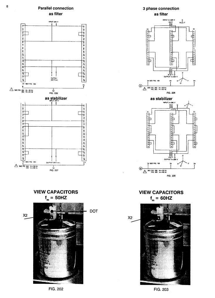
2 CONTENTS... 2 LIST OF FIGURES... 2 ABBREVIATIONS... 2 SAFETY PRECAUTIONS... 3 SYMBOLS IMPAIRED SAFETY PROTECTION IMPORTANT WARNINGS WARNING A WARNING B WARNING C UNPACKING WARNING D GENERAL INTRODUCTION 2. CHARACTERISTICS 2.1 ELECTRICAL DATA GENERAL INPUT OUTPUT OUTPUT EFFECTS AS FILTER AS STABILIZER PROTECTION ENVIRONMENTAL DATA CLIMATIC CONDITIONS ENVIRONMENTAL TESTS 2.3 MECHANICAL DATA OVERALL DIMENSIONS AND WEIGHT MOUNTING 2.4 ACCESSORIES OPERATING MANUAL OPTIONAL DIRECTIONS FOR USE INSTALLATION 3.1 INITIAL INSPECTION 3.2 MOUNTING INSTRUCTIONS 1.3 DISMANTLING 3.4 OUTPUT CONNECTIONS 3.5 MAINS CONNECTION 4 OPERATING INSTRUCTIONS GENERAL INFORMATION 4.2 SWITCHING ON 4.3 CONTROLS, ADJUSTMENTS, INDICATORS AND TERMINALS 4.4 SERIES, PARALLEL, THREE PHASE CONNECTIONS SERIES CONNECTION PARALLEL CONNECTION THREE PHASE CONNECTIONS 5. ADJUSTMENTS GENERAL 5.2 MAINS INPUT 5.3 OUTPUT ADJUSTMENTS 6. SERVICING 6.1 FUSE REPLACEMENT LIST OF FIGURES FIG.... P. 202 VIEW CAPACITORS (50 Hz) VIEW CAPACITORS (60 Hz) CONNECTIONS FILT (50 Hz) CONNECTIONS STAB (50 Hz) CONNECTIONS FILT (60 Hz) CONNECTIONS STAB (60 Hz) PARALLEL CONNECTION as Filter PARALLEL CONNECTION as Stabilizer THREE-PHASE CONNECTION as Filter THREE-PHASE CONNECTION as Stabilizer... 8 ABBREVIATIONS Dm MAINS DISTORTION Do OUTPUT DISTORTION fm MAINS FREQUENCY G EXTERNAL SUPPLY Im MAINS CURRENT Io OUTPUT CURRENT Ion NOMINAL OUTPUT CURRENT r.m.s. ROOT MEAN SQUARE VALUE Ta AMBIENT TEMPERATURE Um MAINS VOLTAGE Umax MAXIMUM OUTPUT VOLTAGE Uo OUTPUT VOLTAGE Uon NOMINAL OUTPUT VOLTAGE TABLE1 CONNECTIONS POSSIBILITIES... 7 PE /10/15/201/202/203/204 2
3 SAFETY PRECAUTIONS In the interests of safety to personnel and equipment it is strongly recommended that this page is read and thoroughly understood by all intended users before attempting to put this instrument into service. The cross-section of the earth conductor must be at least equal to the cross-section of the mains conductors and in accordance with the local safety regulations. This manual contains information and warnings which must be followed by the user to ensure safe operation and to retain the apparatus in a safe condition. Where necessary, warning and caution statements and/or symbols are marked on the apparatus. If the power supply is rack-mounted, the rack must be connected to the Safety Earth in accordance with IEC 348. The cross-section of the earth conductor must be sufficient and depending on the total power of all instruments mounted in this rack. CAUTION is used to indicate correct operating or maintenance procedures in order to prevent damage to or destruction of equipment or other property. WARNING calls attention to a potential danger that requires correct procedures or practices in order to prevent personal injury. SYMBOLS: Read the operating instructions (black/yellow), see Section 4. WARNING B: After delivery, the apparatus must be connected to the power source only by a qualified person. Before making any connection, the safety measures must be thoroughly understood and observed. All adjustments, replacements, repairs, etc... shall be carried out by a qualified person aware of the hazards involved, with the instrument completely disconnected from the mains wherever possible. See IEC 950, Type A, Sec. 1. Protective earth (ground) terminal (black) WARNING C: Any interruption of the protective conductor inside or outside the apparatus, or disconnection of the protective earth terminal is likely to make the apparatus dangerous; intentional interruption is prohibited. IMPAIRED SAFETY PROTECTION For continued protection against fire, only fuses with the required rated current and of the specified type shall be used for replacement (see section 2.1.2). The use of repaired fuses and the short circuiting of fuse holders is prohibited. The instrument shall be disconnected from all voltage sources when a fuse is to be replaced. As the power supply is electronically protected against most faults, a blown fuse indicates a major defect. Before replacing the fuse, always check the electronic circuit. Whenever it is likely that safety protection has been impaired, the instrument must be made inoperative and be secured against any operation. The matter should then be referred to the appropriate servicing authority. Safety protection is likely to be impaired if, for example, the instrument fails to perform the intended measurements or shows signs of damage. UNPACKING On delivery, check the power supply as soon as possible to as certain whether any damage has occurred in transit. Retain all packing materials until all items of the power supply have been accounted for and checked. IMPORTANT WARNINGS Wherever appropriate in the manual, four important warnings are inserted in short, reminder form to maintain subject continuity. However, if there is any doubt about their meaning, always refer to the detailed explanation below. WARNING A: Before any connection is made to a voltage source, the protective earth terminal shall be connected to a protective conductor. The power supply must be earthed in accordance with the IEC348 safety regulations. When a power supply is brought from a cold to a warm environment, condensation may cause a hazardous condition : ensure therefore that the earthing requirements are strictly adhered to. Visual inspection Carry out a mechanical check on, e.g. connectors, terminal blocks, external fuse holders and other items. Check items for dents, chips or other signs of damage. Check that all accessories are present in accordance with the accessories list (Section 2.4). Claims In the event of obvious damage or shortages, or if the safety of the supply is suspect, a claim should be filed with the carrier immediately. ETI should also be notified in order to facilitate the repair of the instrument. WARNING D: If nominal values are changed, the rating type plate must be suitably amended. If a three-core mains cable with mains plug is used, the mains plug shall be inserted into a socket provided with a protective earth contact. The protective action shall not be negated by the use of an extension lead without protective conductor. PE /10/15/201/202/203/204 3
4 4 GENERAL 1.INTRODUCTION The PE /10 (open version) and PE 141../15 /20 (closed version) are line conditioners which deliver a sinewave output with galvanic separation between input and output. The output is short circuit proof. NOTE : The design of this stabilizer is subject to development and improvement. Consequently, this stabilizer may incorporate minor changes in detail from the information contained in this manual. Only values with tolerances or limits can be considered as guaranteed data. Figures without tolerances are informative data without any guarantee. Efficiency (at full load) : min. 89 % OUTPUT ON DELIVERY FILTER CONFIGURATION Type INPUT OUTPUT PE /XX 220 V/50 Hz 220 V For other configurations, see Table OUTPUT EFFECTS 2.CHARACTERISTICS This section deals with the technical specifications of the stabilizer with regard to the input and output conditions, safety aspects and environmental and mechanical data, and gives a list of accessories that are provided with the stabilizer. 2.1 ELECTRICAL DATA The values given in this section are valid within the rated range of operation (-10 C to + 45 C). On delivery, the stabilizer is adjusted at an ambient temperature of 23 C GENERAL * Safety In accordance with Safety Class 1 IEC 380, IEC 435. VDE 550 : only for transformers ( /10, /15) * Leakage current (from chassis to earth): max. 0,5 ma r.m.s. at 50 Hz (on delivery) * Dielectric strength test. Every unit has been factory tested to withstand the following voltages between primary and chassis primary and secondary secondary and chassis 1,5 kvac, during 1 minute 3,75 kvac, during 1 minute 1,5 kvac, during 1 minute In the event of repetition of the dielectric strength tests, it is necessary to follow the instructions laid down in the Service Manual. If the Service Manual is not in stock ETI must be contacted in order to obtain the supplementary information. * Output terminals : the output terminals are floating with respect to earth. The voltage between any one of the output terminals and earth may not exceed 500 VAC.(r.m.s.) * Noise level. PE 141. /.. : max. 50 dba INPUT Mains voltage (ac.) nominal ; mains frequency 220 V (50 Hz) or 220 V / 240 V (60 Hz) by wiring Consumption, input current Type Im (1) Fuses (2) PE 1411 /XX 1,3 A 3,15 A PE 1412/XX 2.5 A 6,3 A PE 1413/XX 5 A 10 A PE 1414/XX 8,6 A 16 A (1) at mains voltage of 220 V (2) fuses provided by the user and mounted outside the stabilizer AS FILTER Output voltage nominal value Uon : 220 V r.m.s. (+ 1, -1) % or 240 V r.m.s. (+ 2, -2) % Source effect (Um : + 10 % or - 10 %) Valid for a constant mains frequency of 50 Hz, an input distortion of max. 5 % and a linear resistive load between no load and full load. max. -2 %, + 2 % Combined load and source effect (Um and 1.) Valid for a constant mains frequency of 50 Hz, an input distortion of max. 5 % and a linear resistive load between no load and full load: max. -2,9 %, + 6,0 % from Uon PE 1411 max. -2,5 %, + 4,9 % from Uon PE 1412 max. -2,1 %, + 4,5 % from Uon PE 1413 max. -1,8 %, + 4,2 % from Uon PE 1414 Warm-up time: 4 hours with a cold core (+ 25oC), the output voltage is approximately 1,5 % higher. * Distortion (output) max. 4 % under all conditions referred to under source and load effect. * Transient suppression : min. 60 db for asymmetrical pulses *Source frequency effect (f. : 50 Hz +/-2%or6OHz +/-2%) For each 1 % mains frequency variation, the max. output variation is 1,5 % AS STABILIZER Output voltage nominal value Uon : 220 V r.m.s. (+ 1, -1) % or 240 V r.m.s. (+ 2, -2) % Source effect (U. : + 10 % or - 10 %) Valid for a constant mains frequency of 50 Hz, an input distortion of max. 5 % and a linear resistive load between no load and full load. max. -1%, + 1 % * Combined load and source effect (Um and 1.) Valid for a constant mains frequency of 50 Hz, an input distortion of max. 5 % and a linear resistive load between no load and full load: max. -1,9 %, + 3,0 % from Uon PE 1411 max. -1,6 %, + 2,8 % from Uon PE 1412 max. -1,2 %, + 2,3 % from Uon PE 1413 max. -1,0 %, + 2,0 % from Uon PE 1414 Warm-up time: 4 hours with a cold core (+ 25 C), the output voltage is approximately 1,5 % higher. * Distortion (output) max. 4 % under all conditions referred to under source and load effect. * Transient suppression : unit Al : min. 30 db for asymmetrical pulses * Source frequency effect (f. : 50 Hz + /-2% or 60 Hz + /-2%) For each 1 % mains frequency variation, the max. output variation is 1,5%. PE /10/15/201/202/203/204 4
5 2.1.5 PROTECTION Short circuit current : between 150 % and 200 % of the nominal current. 2.2 ENVIRONMENTAL DATA The environmental data mentioned in this manual are based on the results of the manufacturer's checking procedures CLIMATIC CONDITIONS Designation Ambient temperature rated range of use limit range of operation limit range for storage and transport (-10/ + 45) C (-20/ + 45) C (-40/ + 70) C Relative humidity (of ambient air) (20/90) % COOLING non condensing - The ambient temperature is defined as the temperature 20 mm below the unit. Mount the line conditioner unit with the cooling surfaces in a vertical plane so that the air circulation in the unit is maximum. - The current values given in Section may be only applied when the unit is in a free-standing position and the rising warmed air is not impeded ENVIRONMENTAL TESTS Performance tests, operating Description IEC 68 Cold test Dry heat Damp heat steady state Tests for storage and transport Description IEC 68 Cold test Dry heat Vibration test Bump test Cyclic damp heat test 2 Packaging 2-1 Ad 2 h. (- 20 C) 2-2 Bd 2 h. (+ 40 C) 2-3 Ca 10 d. (+ 40 C) 2-8 Ab 72 h. (-40 C) 2-8 Bd 96 h. (+70 C) 2-6 Fc 2-29 Eb 2-30 Db 21 d. (+ 25 C to + 40 C) (90-100) % RH according to UN-D-1400 The test methods mentioned are in accordance with those of the relevant ISO-Standards. 2.3 MOUNTING Connecting block : INPUT X1 (/10 /15), mains supply cable (/20) OUTPUT X1 (/10 /15), X3 wall plug (/20) 2.4 OPTIONAL ACCESSORIES Plugs and sockets for versions : /201 valid in Germany, Austria, Holland, Sweden,. /202 valid in Belgium, France,. /203 valid in Great-Britain, Hong-Kong,. /204 valid in Switzerland. DIRECTIONS FOR USE 3. INSTALLATION 3.1 INITIAL INSPECTION Refer to Safety Precautions and Unpacking SEE WARNING A - PROTECTIVE EARTHING /10/15 Connect the stabilizer to a protective earth : terminal X4 /20 Provided with a main plug with earth contact. 3.2 MOUNTING INSTRUCTIONS SEE WARNING A - PROTECTIVE EARTHING A line conditioner attains a nominal working temperature higher than a conventional transformer, due to the high flux density in the core. A physical spacing and/or orientation of the transformer field must be realized to avoid interactions with circuits like audio, CRT displays, etc DISMANTLING SEE WARNING B - Before handling or dismantling first disconnect from all voltage sources. Opening : The apparatus can be accessed by removing the cover. 3.4 OUTPUT CONNECTIONS NOTE: The output effects given in Section can be influenced by external connections or parameters (e.g. cross-sections of the load connections, distance between output terminals and load, characteristics of the load). /10 /15 version : Connecting block X1 (max. cross-section :1,5 MM²) The cross-section of the wires must be of adequate current-carrying capacity (also dependent on the distance between the line conditioner and the load). /20 version output :wall plug on the front panel 3.5 MAINS CONNECTION Before inserting the mains plug into the mains socket, make sure that the instrument is set to the local mains voltage. NOTE: If the mains plug has to be adapted to the local situation. such adaptation should be done by a qualified person only! SEE WARNING A - (protective earthing); Page 3 SEE WARNING B - (authorized mains connection & disconnection procedures). Page 3 SEE WARNING C - (fuse types and renewal procedure).page 3 SEE WARNING D - Page 3 Connect the power supply to the ac. mains voltage by means of a connector mains supply cable. PE /10/15/201/202/203/204 5
6 The current-carrying wires to the mains must be of sufficient cross section depending on the mains voltage and the distance between the mains and the stabilizer.. 4. OPERATING INSTRUCTIONS 4.1 GENERAL INFORMATION This section outlines the procedures and precautions necessary for operation. It identifies and briefly describes the functions of front and rear panel controls and indicators, and explains the practical aspects of operation to enable an operator to evaluate quickly the instrument's main functions. 4.2 SWITCHING "ON" 5.2 MAINS INPUT On delivery the stabilizer is wired for input voltage : 220 V mains frequency : 50 Hz configuration : as "FILTER" For other configurations, see Table 1. For 110 V mains connections, please contact ETI. 5.3 OUTPUT ADJUSTMENTS (See Fig. 220) On delivery the stabilizer is wired for output voltage configuration : 220 V : as "FILTER" For other configurations, see Table 1. After the stabilizer has been connected to the mains voltage in accordance with Section 3.1 the instrument is ready for use. With normal installation in accordance with Section 3 and after a warming-up time of 4 hours the characteristics specified in Section 2 are valid. 6. SERVICING See WARNING B; Servicing by qualified person only! For other technical information is required, please contact ETI. 4.3 CONTROLS, ADJUSTMENTS, INDICATORS AND TERMINALS Front panel : Hl indicates the presence of the output voltage (/20 version) S1 switch ON/OFF X3 wall plug 4.4 SERIES, PARALLEL, THREE-PHASE CONNECTIONS SERIES CONNECTION Not applicable PARALLEL CONNECTION Stabilizers of the same type may be connected in parallel, for technical information please contact ETI THREE-PHASE CONNECTIONS Safety measures require that the instrument should first be put into its original state and that the spare parts are identical to the original components. WARNING -To increase the efficiency of the line conditioner, it is better to use shielded output cables. - For low frequency noise, connect the shield to the ground at one end (receiving side) only. - For high frequency noise, connect the shield to the ground at both ends. - To reduce EMI coupling from other cables and outside EMI ambients, each cable (input, output cable) must be separated from the others : input and output cables should not be near or in parallel to each other. The output cable should be kept from clear of power cables. -Some EMI problems can be solved by grounding: for 3 phases and parallel configuration, the centralized point ground is the most effective in all conditions. Stabilizers of the same type may be connected in a three-phase configuration; for technical information please contact ETI. 5. ADJUSTMENTS See WARNING B adjustments by qualified person only. 5.1 GENERAL WARNING D: when changing the nominal values, the rating type-plate must be suitably amended, Adjustments can be made after opening the apparatus. (see Section 3.3) PE /10/15/201/202/203/204 6
7 PE /10/15/201/202/203/204 7
8 PE /10/15/201/202/203/204 8
& HIGH CURRENT DC POWER SUPPLIES INSTRUCTION MANUAL
 72-6850 & 72-6852 HIGH CURRENT DC POWER SUPPLIES INSTRUCTION MANUAL Table of Contents Introduction 2 Specification 2 Safety 4 EMC 5 Installation 6 Connections 6 Operation 7 Maintenance and Repair 8 www.tenma.com
Matrix APAX. 380V-415V 50Hz TECHNICAL REFERENCE MANUAL
 Matrix APAX 380V-415V 50Hz TECHNICAL REFERENCE MANUAL WARNING High Voltage! Only a qualified electrician can carry out the electrical installation of this filter. Quick Reference ❶ Performance Data Pages
REFERENCE MANUAL FORM: MX-TRM-E REL REV MTE
 Matrix APAX 380V-415V 50Hz TECHNICAL REFERENCE MANUAL FORM: MX-TRM-E REL. September 2014 REV. 002 2014 MTE Corporation WARNING High Voltage! Only a qualified electrician can carry out the electrical installation
Users Manual. Accessories Motor and Phase Rotation Indicator ships with the following items: 3 test leads 3 test probes 3 alligator clips 9 V battery
 MS5900 Users Manual Table of Contents Introduction Motor and Phase Rotation Indicator is a handheld, battery-operated instrument designed to detect the rotary field of three-phase systems and determine
99 Washington Street Melrose, MA Fax TestEquipmentDepot.com. Instruction Manual. Model 2831D 4 ½ Digit True RMS Digital Multimeter
 99 Washington Street Melrose, MA 02176 Fax 781-665-0780 TestEquipmentDepot.com Instruction Manual Model 2831D 4 ½ Digit True RMS Digital Multimeter 1 1. PRODUCT DESCRIPTION 1-1. Introduction Thank you
High Frequency SineWave Guardian TM
 High Frequency SineWave Guardian TM 380V 480V INSTALLATION GUIDE FORM: SHF-IG-E REL. January 2018 REV. 002 2018 MTE Corporation High Voltage! Only a qualified electrician can carry out the electrical installation
M T E C o r p o r a t i o n MATRIX FILTER. SERIES B Volts, 50HZ USER MANUAL PART NO. INSTR REL MTE Corporation
 M T E C o r p o r a t i o n MATRIX FILTER SERIES B 380-415 Volts, 50HZ USER MANUAL PART NO. INSTR - 015 REL. 040709 2003 MTE Corporation IMPORTANT USER INFORMATION NOTICE The MTE Corporation Matrix Filter
INSTRUCTION MANUAL. Type SWF. Sine Wave Filters 480 Volts, 60Hz. Page 1 of 14. April 15, 2010: updated capacitor UL File number)
") POWER QUALITY INSTRUCTION MANUAL Type SWF Sine Wave Filters 480 Volts, 60Hz April 15, 2010: updated capacitor UL File number) Page 1 of 14 Contents 1. Introduction & SAFETY 2. Theory of operation 3. Advantage
POWER QUALITY INSTRUCTION MANUAL Type SWF Sine Wave Filters 480 Volts, 60Hz April 15, 2010: updated capacitor UL File number) Page 1 of 14 Contents 1. Introduction & SAFETY 2. Theory of operation 3. Advantage
M T E C o r p o r a t i o n MATRIX FILTER. SERIES B Volts, 50HZ USER MANUAL PART NO. INSTR REL MTE Corporation
 M T E C o r p o r a t i o n MATRIX FILTER SERIES B 380-415 Volts, 50HZ USER MANUAL PART NO. INSTR - 015 REL. 060628 2006 MTE Corporation IMPORTANT USER INFORMATION NOTICE The MTE Corporation Matrix Filter
Technical Information Manual
 Technical Information Manual Revision n. 4 18 June 2008 MOD. A3000NF 3-PHASE NOTCH FILTER MANUAL REV. 4 NPO: 00120/04:3000N.MUTx/04 CAEN will repair or replace any product within the guarantee period if
MTE SERIES RLW. World REACTORS USER MANUAL PART NO. INSTR 030 REL MTE Corporation
 MTE SERIES RLW World REACTORS USER MANUAL PART NO. INSTR 030 REL. 090529 2009 MTE Corporation IMPORTANT USER INFORMATION NOTICE MTE Series RLW Line/Load Reactors are components designed to improve the
EPS/ELA-Series User Manual EPS/ELA 250W
 EPS/ELA-Series User Manual EPS/ELA 250W EPS Stromversorgung GmbH Tel: +49 (0)821 570451 0 Index 3 Page: 1 Table of contents: Page 1. Features of ELA-Series... 3 1.1 Basic Functions... 3 1.2 Options...
M T E C o r p o r a t i o n. dv/dt Filter. Series A VAC USER MANUAL PART NO. INSTR REL MTE Corporation
 M T E C o r p o r a t i o n dv/dt Filter Series A 440-600 VAC USER MANUAL PART NO. INSTR - 019 REL. 041119 2004 MTE Corporation IMPORTANT USER INFORMATION NOTICE The MTE Corporation dv/dt Filter is designed
TOWER MAXI T SINGLE CONVERSION ON LINE UPS SYSTEMS
 INSTRUCTION MANUAL TOWER MAXI T SINGLE CONVERSION ON LINE UPS SYSTEMS September 2000 TOWER UPS DISTRIBUTION (PTY) LTD 1 1. INTRODUCTION T A B L E O F C O N T E N T S 1.1 General Description... 3 1.2 Features...
ISO-TECH IPS1810H and IPS1603D DC power supply ISO-TECH IPS 1810H et IPS 1603D Alimentation électrique c.c.
 ISO-TECH IPS1810H and IPS1603D DC power supply ISO-TECH IPS 1810H et IPS 1603D Alimentation électrique c.c. ISO-TECH IPS 1810H 204-713 ISO-TECH IPS 1603D 204-729 82IP-1810HME Ei Statement of Compliance
Wilo-Control SC-Fire Jockey
 Pioneering for You Wilo-Control SC-Fire Jockey de en fr Einbau- und Betriebsanleitung Installation and operating instructions Notice de montage et de mise en service nl Inbouw- en bedieningsvoorschriften
Declaration of Conformity
 We Declaration of Conformity GOOD WILL INSTRUMENT CO., LTD. No. 7-1, Jhongsing Rd, Tucheng City, Taipei County 236, Taiwan GOOD WILL INSTRUMENT (SUZHOU) CO., LTD. No.69 Lushan Road, Suzhou New District
Appendix: Safety and application notes for... 15
 Contents Safety... 2 Warnings... 2 Symbols used in this manual... 2 Operator s safety... 2 Avoid filter module damage... 2 DC-link resonance... 2 Description... 3 Description... 3 Ordering numbers, 380-415
Matrix AP 400V 690V INSTALLATION GUIDE. Quick Reference. ❶ How to Install Pages 6 20 ❷ Startup/Troubleshooting Pages WARNING
 Matrix AP 400V 690V INSTALLATION GUIDE FORM: MAP-IG-E REL. May 2017 REV. 002 2017 MTE Corporation WARNING High Voltage! Only a qualified electrician can carry out the electrical installation of this filter.
DUAL 60V 20A POWER FLEX POWER SUPPLY INSTRUCTION MANUAL
 72-7570 DUAL 60V 20A POWER FLEX POWER SUPPLY INSTRUCTION MANUAL Table of Contents Specification 1 Safety 3 EMC 4 Installation 5 Connections 5 Operation 6 Maintenance 8 Specification General specifications
OPERATING AND MAINTENANCE MANUAL. Primary Current Injection Test Set. 750ADM-H mk2
 OPERATING AND MAINTENANCE MANUAL Product: Type: Primary Current Injection Test Set 750ADM mk2 750ADM-H mk2 DESIGNED AND MANUFACTURED BY: T & R Test Equipment Limited 15-16 Woodbridge Meadows, Guildford,
DIGITAL RCD(ELCB) TESTER
 TESTER") INSTRUCTION MANUAL DIGITAL RCD(ELCB) TESTER KEW 5410 R KYORITSU ELECTRICAL INSTRUMENTS WORKS, LTD. Contents 1. Safety Warnings.... 1 2. Procedure of removing Cover. 3 2-1 Method of removing the Cover.
INSTRUCTION MANUAL DIGITAL RCD(ELCB) TESTER KEW 5410 R KYORITSU ELECTRICAL INSTRUMENTS WORKS, LTD. Contents 1. Safety Warnings.... 1 2. Procedure of removing Cover. 3 2-1 Method of removing the Cover.
DC POWER SUPPLY ALIMENTATION C.C.
 DC POWER SUPPLY ALIMENTATION C.C. ISO-TECH IPS 303A 201-3424 ISO-TECH IPS 601A 201-3446 SAFETY TERMS AND SYMBOLS These terms may appear in this manual or on the product: WARNING. Warning statements identify
KV4-300 mk2. KV5-200 mk2. KV5-100T mk2. KV3-250 mk2
 OPERATING AND MAINTENANCE MANUAL Product: Type: High Voltage AC Test Set KV3-250 mk2 KV4-300 mk2 KV5-100 mk2 KV5-100T mk2 KV5-200 mk2 DESIGNED AND MANUFACTURED BY: T & R Test Equipment Limited 15-16 Woodbridge
MULTIVOLT 2605 SERIES POWER CONDITIONER 50 Hz
 REPAIR If poor performance is confirmed (refer SERVICING information on Page 11 of this Manual) you should contact Eaton Power Quality National Service operation. If the unit is to be returned to Invensys
dv Sentry TM 208V 600V INSTALLATION GUIDE Quick Reference ❶ How to Install Pages 6 14 ❷ Startup/Troubleshooting Pages WARNING
 dv Sentry TM 208V 600V INSTALLATION GUIDE FORM: DVS-IG-E REL. January 2018 REV. 003 2018 MTE Corporation High Voltage! Only a qualified electrician can carry out the electrical installation of this filter.
Technical Manual Electrical Power Supply System T4002
 Technical Manual Electrical Power Supply System T400 MOZELT GmbH & Co. KG Please observe the following safety information and recommendations before start-up! Copyright: MOZELT GmbH & Co. KG, D-4769 Duisburg
LCL FILTERS INSTRUCTIONS MANUAL (M A) (c) CIRCUTOR S.A.
 (c) CIRCUTOR S.A.") LCL FILTERS INSTRUCTIONS MANUAL (M98121701-03-09A) (c) CIRCUTOR S.A. ------ LCL filters: Instructions Manual ----- Page 2 TABLE OF CONTENTS TABLE OF CONTENTS 2 1 CHECKS ON RECEIPT OF THE EQUIPMENT. 3 2
LCL FILTERS INSTRUCTIONS MANUAL (M98121701-03-09A) (c) CIRCUTOR S.A. ------ LCL filters: Instructions Manual ----- Page 2 TABLE OF CONTENTS TABLE OF CONTENTS 2 1 CHECKS ON RECEIPT OF THE EQUIPMENT. 3 2
TC-500PD8. Switching Power Supply ( PS2 A T X 500W 8 0+ ) SPECIFICATION. Revision: 2.0
 SPECIFICATION. Revision: 2.0") TC-500PD8 TC-500PD8 Switching Power Supply ( PS2 A T X 500W 8 0+ ) SPECIFICATION Revision: 2.0 727,. Phillips Drive City of Industry. CA 91748. USA http:// www.xeal.com.tw TEL: 626-303-8885 FAX: 626-301-0588
TC-500PD8 TC-500PD8 Switching Power Supply ( PS2 A T X 500W 8 0+ ) SPECIFICATION Revision: 2.0 727,. Phillips Drive City of Industry. CA 91748. USA http:// www.xeal.com.tw TEL: 626-303-8885 FAX: 626-301-0588
UV- TECHNOLOGY. Technical Documentation ELC N6 / ELC N8 / ELC N10
 our name is our principle UV- TECHNOLOGY Technical Documentation ELC N6 / ELC N8 / ELC N10 GB eta plus electronic gmbh Lauterstraße 29, D-72622 Nürtingen, Telefon +49 (0) 70 22-60 02-80, Fax +49 (0) 70
Mounting and Operating Instructions EB 5868/5869 EN
 Electric Control Valves Types 3213/5857, 3213/5824, Types 3214/5824, 3214/3374, 3214/3274 with safety function: Types 3213/5825, 3214/5825, 3214/3374, 3214/3274 Pneumatic Control Valves Types 3213/2780-1,
M T E C o r p o r a t i o n. MTE Series RL. Line/ load Reactors USER MANUAL PART NO. INSTR -011 REL MTE Corporation
 M T E C o r p o r a t i o n MTE Series RL Line/ load Reactors USER MANUAL PART NO. INSTR -011 REL. 050516 2002 MTE Corporation IMPORTANT USER INFORMATION NOTICE MTE Series RL Line/Load Reactors are components
Triple Output Power Supply
 Test Equipment Depot - 800.517.8431-99 Washington Street Melrose, MA 02176 TestEquipmentDepot.com Model 1672, 1673 Triple Output Power Supply INSTRUCTION MANUAL 1 Safety Summary The following safety precautions
50 Hz Mini/Micro Computer Regulator (MCR) Series Installation and Operation Manual
 Series Installation and Operation Manual") Operating & Service Instructions Sola Minicomputer Regulators UL White Card Listed Power Supply Classification CSA Certified Transformer Classification General Description and Specifications The Sola Micro/Minicomputer
Operating & Service Instructions Sola Minicomputer Regulators UL White Card Listed Power Supply Classification CSA Certified Transformer Classification General Description and Specifications The Sola Micro/Minicomputer
Switching DC Power Supply
 99 Washington Street Melrose, MA 02176 Phone 781-665-1400 Toll Free 1-800-517-8431 Visit us at www.testequipmentdepot.com Model 1693, 1694 Switching DC Power Supply INSTRUCTION MANUAL 1 Safety Summary
Rental Industry Safety Tester Safe Check 5s
 Rental Industry Safety Tester Safe Check 5s Feb 2006 2006 Clare Instruments Inc. Issue 2.0 Firmware Version : 1.2a Limited Warranty & Limitation of Liability Clare Instruments Inc, guarantees this product
SineWave Guardian TM 380V 600V INSTALLATION GUIDE. Quick Reference. ❶ How to Install Pages 6 17 ❷ Startup/Troubleshooting Pages WARNING
 SineWave Guardian TM 380V 600V INSTALLATION GUIDE FORM: SWG-IG-E REL. October 2018 REV. 003 2018 MTE Corporation High Voltage! Only a qualified electrician can carry out the electrical installation of
www. ElectricalPartManuals. com Instruction Bulletin ALTIVAR FLEX58 TRX Adjustable Speed Chassis Drive Controllers Installation Guide
 Instruction Bulletin ALTIVAR FLEX58 TRX Adjustable Speed Chassis Drive Controllers Installation Guide Retain for future use. 30072-450-47A July 2002 Raleigh, NC, USA HAZARDOUS VOLTAGE Read and understand
User Manual Rittal PMC UPS 6kVA
 User Manual Rittal PMC UPS 6kVA Germany Rittal GmbH & Co. KG Auf dem Stützelberg D-35745 Herborn Tel.: ++49-27 72-5 05-0 Fax: ++49-27 72-5 05-23 19 Internet: www.rittal.de 26 Contents 1. Introduction...
Instruction Manual. Harmonic Filter AHF 005/010. Drives Solutions
 Harmonic Filter AHF 005/010 Instruction Manual Drives Solutions Contents Safety... 2 Warnings... 2 Symbols used in this manual... 2 Operator s safety... 2 Avoid filter module damage... 2 DC-link resonance...
1.Safe testing IMPORTANT:
 Electricity is dangerous and can cause injury and death. Always treat it with the greatest of respect and care. If you are not quite sure how to proceed, then stop, take advice from a qualified person.
Pulsar Evolution 1500 / 1500 Rack 1100 / 1100 Rack 800 / 800 Rack 500 Rack
 www.mgeups.com MGE UPS SYSTEMS Pulsar Evolution 1500 / 1500 Rack 1100 / 1100 Rack 800 / 800 Rack 500 Rack Installation and user manual S T O P Y O U N O W L L W I N G I T H N O 34007117EN/AB - Page 1 Page
SST-ST75F-ESS The essential silver standard
 STRIDER ESSENTIAL SERIES SST-ST75F-ESS The essential silver standard High efficiency with 80 PLUS Silver certification 24/7 continuous power output with 40 operating temperature Class-leading single +12V
Operating Instructions. International English. CCS Dust Extractor
 Operating Instructions International English CCS Dust Extractor Electric Cast Saw Dust Removal System Warnings & Safety Rules WARNING!: THIS EQUIPMENT MUST BE EARTHED! Danger!: Possible explosion hazard
Proportional directional valve, pilot-operated, with integrated electronics (OBE)
") Proportional directional valve, pilot-operated, with integrated electronics (OBE) Type WFCE RE 943 Edition: 7- Replaces: 6- Size 6 5 Component series X Maximum operating pressure 4 bar Maximum flow 5 l/min
Proportional directional valve, pilot-operated, with integrated electronics (OBE) Type WFCE RE 943 Edition: 7- Replaces: 6- Size 6 5 Component series X Maximum operating pressure 4 bar Maximum flow 5 l/min
AIR COOLED RECTIFIER SPECIFICATION S-50-A
 SPECIFICATIONS AIR COOLED RECTIFIER Spec50a1 5JAN1999 SPECIFICATION S-50-A HIGH VOLTAGE SINGLE TRANSFORMER AIR COOLED RECTIFIER Standard output power range: 250 to 600 volts at 100 to 1,200 amperes TECHNICAL
TURBOTRONIK NT 151/361
 Vakuum-Lösungen Applikations- Unterstützung Service LEYBOLD VAKUUM GA 05.214/7 TURBOTRONIK NT 151/361 Elektronischer Frequenzwandler Electronic Frequency Converter Kat.-Nr. / Cat. No. 857 15/16/17/18/19
USER MANUAL. Power GUARD UPS. Uninterruptible Power System
 USER MANUAL Power GUARD UPS Uninterruptible Power System IMPORTANT SAFETY INSTRUCTIONS SAVE THESE INSTRUCTIONS This manual contains important instructions for Power GUARD that should be followed during
Use. Functions. OpenAir TM. Rotary version, modulating, with spring return, AC 24 V
 4 637 OpenAir TM Air damper actuators Rotary version, modulating, with spring return, AC 24 V GCA16...1 Electromotive rotary actuators, DC 0...10 modulating control signal, nominal torque 16 Nm, spring
ZWD225PAF Series Instruction Manual
 Instruction Manual BEFORE USING THE POWER SUPPLY UNIT Pay attention to all warnings and cautions before using the unit. Incorrect usage could lead to an electrical shock, damage to the unit or a fire hazard.
IB IL 24 PWR IN/F-D IB IL 24 PWR IN/F-D-PAC
 IB IL 24 PWR IN/F-D IB IL 24 PWR IN/F-D-PAC Inline Power Terminal With Fuse and Diagnostics Data Sheet 5569C 02/2003 # # $ ' ) The IB IL 24 PWR IN/F-D and IB IL 24 PWR IN/F-D-PAC only differ in the scope
ILED Aquarius Illuminated Windsock. User Manual
 Contents 1. Safety... 3 2. Warranty... 3 2.1 General... 3 2.2 Life span... 3 3. Type plate... 4 3.1 The light fitting has a type plate:... 4 3.2 The junction box has a type plate:... 5 4. Product Description...
1. INTRODUCTION SYSTEM DESCRIPTION Front Panel CONNECTION AND OPERATION TROUBLESHOOTING...8
 Contents : 1. INTRODUCTION...1 2. IMPORTANT SAFETY INSTRUCTIONS...2 3. SYSTEM DESCRIPTION...4 3.1 Front Panel...4 4. CONNECTION AND OPERATION...6 5. TROUBLESHOOTING...8 6. MAINTENANCE...9 6.1 Operation...9
MODEL A96 SERIES. 130Vdc Switchmode Utility Rectifier / Battery Charger. Used with LaMarche Power Cage ECN/DATE
 MODEL A96 SERIES 130Vdc Switchmode Utility Rectifier / Battery Charger Used with LaMarche Power Cage CPN112138 ECN/DATE ISSUE DATE: ECN 17010-12/05 106 BRADROCK DRIVE DES PLAINES, IL. 60018-1967 (847)
THREE PHASE AND SINGLE PHASE ASYNCHRONOUS ELECTRIC MOTORS OPERATION AND MAINTENANCE BOOKLET Rev
 MORATTO S.R.L. Electrical Machinery I 31030 PERO DI BREDA (Treviso) Italy Via A Volta, 2 Tel. +390422904032 fax +39042290363 www. moratto.it - moratto@moratto.it THREE PHASE AND SINGLE PHASE ASYNCHRONOUS
Battery Chargers Sealed or Valve Regulated Lead Acid Batteries Models: PSC A AND PSC A
 Battery Chargers Sealed or Valve Regulated Lead Acid Batteries Models: PSC-122000A AND PSC-241000A Operating Instructions WARNING CONCERNING THE REMOVAL OF COVER: CAUTION: TO PREVENT THE RISK OF ELECTRIC
E-15 Uninterruptible Power Systems (UPS)
") Guideline No.E-15 (201705) E-15 Uninterruptible Power Systems (UPS) Issued date: May 9, 2017 China Classification Society Foreword This Guideline is a part of CCS Rules, which contains technical requirements,
Guideline No.E-15 (201705) E-15 Uninterruptible Power Systems (UPS) Issued date: May 9, 2017 China Classification Society Foreword This Guideline is a part of CCS Rules, which contains technical requirements,
SD, SE, SDE, SCO series Multipole switchgear for rail vehicles: Disconnecting switches, Earthing Switches, Disconnector with Earthing Switches,
 4 Electrics for Rolling Stock Multipole switchgear for rail vehicles: Disconnecting switches, Earthing Switches, Disconnector with Earthing Switches, Change-Over-Switches 600 V to 3 kv Catalogue F84.en
SPECIFICATION FSP350-60APN(85) Bronze. (Erp2013) DATE:MAY, 14, 2013 表單編號 :7000P Page1
 Bronze. (Erp2013) DATE:MAY, 14, 2013 表單編號 :7000P Page1") SPECIFICATION FSP350-60APN(85) Bronze (Erp2013) DATE:MAY, 14, 2013 REV:2 表單編號 :7000P-0105 Page1 TABLE OF CONTENTS PAGE 1. GENERAL REQUIREMENTS 3 2. INPUT REQUIREMENTS 3 3. OUTPUT REQUIREMENTS 3 3.1 Output
SPECIFICATION FSP350-60APN(85) Bronze (Erp2013) DATE:MAY, 14, 2013 REV:2 表單編號 :7000P-0105 Page1 TABLE OF CONTENTS PAGE 1. GENERAL REQUIREMENTS 3 2. INPUT REQUIREMENTS 3 3. OUTPUT REQUIREMENTS 3 3.1 Output
Rescue Pac. Please read and fully understand the instructions in this manual before operation. Keep this manual safe for future reference
 Please dispose of Packaging for the product in a responsible manner. It is suitable for recycling. Help to protect the environment, take the packaging to the local amenity tip and place into the appropriate
Electronic Ballast EVG 2000-T
 Electronic Ballast EVG 2000-T Operating Manual Table of contents 1 Description 1.1 Advantages of this ballast... 3 1.2 Functional principle... 3 1.3 Energization... 4 1.4 Visualization... 5 1.5 Indications
Thyristor power controller TE10A. Burst-firing Single-cycle Advanced Single-cycle
 Thyristor power controller TE10A Burst-firing Single-cycle Advanced Single-cycle Control of short-wave infrared elements and loads of constant resistance up to 20kW User Manual Copyright Eurotherm Automation
Guideline No.: E-07(201610) E-07 TRANSFORMERS. Issued date: October 28,2016. China Classification Society
 E-07 TRANSFORMERS. Issued date: October 28,2016. China Classification Society") Guideline No.: E-07(201610) E-07 TRANSFORMERS Issued date: October 28,2016 China Classification Society Foreword: This Guide is a part of CCS Rules, which contains technical requirements, inspection and
Guideline No.: E-07(201610) E-07 TRANSFORMERS Issued date: October 28,2016 China Classification Society Foreword: This Guide is a part of CCS Rules, which contains technical requirements, inspection and
Variable Regulated Voltage Power Supply Instruction Manual Model XP-605 / XP-752A
 Variable Regulated Voltage Power Supply Instruction Manual Model XP-605 / XP-752A Copyright Elenco Electronics, Inc. REV-D DC POWER SUPPLY 1 2 4 5 CURRENT VOLTAGE 13 3 6 C.C. C.V. 7 FINE COARSE FINE COARSE
Guideline No.: E-07(201712) E-07 TRANSFORMERS. Issued date: December 26, China Classification Society
 E-07 TRANSFORMERS. Issued date: December 26, China Classification Society") Guideline No.: E-07(201712) E-07 TRANSFORMERS Issued date: December 26, 2017 China Classification Society Foreword: This Guide is a part of CCS Rules, which contains technical requirements, inspection
Guideline No.: E-07(201712) E-07 TRANSFORMERS Issued date: December 26, 2017 China Classification Society Foreword: This Guide is a part of CCS Rules, which contains technical requirements, inspection
Ordering Information. Switching Power Supply S82F. Industrial-Grade Power Supply for General or Peak Load Applications SWITCHING POWER SUPPLIES
 Switching Power Supply S82F Industrial-Grade Power Supply for General or Peak Load Applications Correct input voltage range is automatically selected: 1 VAC or 2 VAC. Model S82F-P is suitable for peak
Appendix: Safety and application notes for 19
 Contents Safety 2 Warnings 2 Symbols used in this manual 2 Operator's safety 2 Avoid filter module damage 2 DC-link resonance 2 Description 3 Description 3 Ordering numbers, 380-415 V, 50 Hz 4 Ordering
JANDS DD-8. Technical Manual. Version 1.0
 JANDS DD-8 O p t o - I s o l a t e d D M X S p l i t t e r Technical Manual Version 1.0 EMC COMPLIANCE This product is approved for use in Europe and Australia/New Zealand and conforms to the following
i400s Calibration Information Introduction
 i400s AC Current Clamp Introduction XWWarning To avoid electric shock or injury, do not perform the performance tests or calibration procedures unless you are qualified to do so. The information provided
Pro Booster 802Li. Please read and fully understand the instructions in this manual before operation. Keep this manual safe for future reference.
 Please dispose of packaging for the product in a responsible manner. It is suitable for recycling. Help to protect the environment, take the packaging to the local amenity tip and place into the appropriate
C B. Operating up to 5000m altitude 5 year product warranty Models
 DC/DC Converter Wide 2:1 input voltage 6 W DC/DC converter in a compact DIP-24 plastic case I/O isolation 5000 VACrms rated for 250 VACrms working voltage Certification according to IEC/EN/ES 60601-1 3rd
R&S RT-ZC02 R&S RT-ZC03 AC/DC Current Probe User Manual
 R&S RT-ZC02 R&S RT-ZC03 AC/DC Current Probe User Manual / User Manual Content 1 Introduction 3 2 Safety 3 3 Specifications RT-ZC03 6 Specifications RT-ZC02 7 4 Operating Instructions RT-ZC03 8 Operating
MAKING MODERN LIVING POSSIBLE. UniLynx Indoor Installation Manual. ULX 1800i ULX 3000i ULX 3600i ULX 5400i SOLAR INVERTERS
 MAKING MODERN LIVING POSSIBLE UniLynx Indoor Installation Manual ULX 1800i ULX 3000i ULX 3600i ULX 5400i SOLAR INVERTERS Contents Contents 1. Introduction 2 Introduction 2 Installation Sequence 2 Important
Switching Power Supply
 Switching Power Supply Easy-to-use Industrial Power Supply with Versatile Functions (); Power Supply Suitable for Peak Loads such as Motors and Solenoids (-P) Remote control function incorporated. Remote
Data Bulletin. ALTIVAR FLEX58 Chassis Drive Controllers Class 8806 INTRODUCTION DESIGN CONCEPT. Bulletin No. 8806DB0102 August 2001 Raleigh, NC, USA
 Data Bulletin Raleigh, NC, USA ALTIVAR FLEX58 Chassis Drive Controllers Class 8806 INTRODUCTION The ALTIVAR FLEX58 chassis drive controller offers OEMs, panel builders, integrators, and users a unique
ZWD100PAF Series Instruction Manual
 Instruction Manual BEFORE USING THE POWER SUPPLY UNIT Pay attention to all warnings and cautions before using the unit. Incorrect usage could lead to an electrical shock, damage to the unit or a fire hazard.
Input voltage Power rating Output voltage Output current With Front mounting Bracket. With DIN-rail mounting Bracket 400/480 VAC
 Three-phase Input Switch Mode S8PE DIN-rail mounting, 3-phase input Switch mode Supply with a range of 5A to 40A output current 3 phase 400/480 or 200/230 VAC input 5, 10, 20 and 40A; 24 VDC output Higher
Contents. Introduction Inspection Notes on Safety Precautions. Chapter 1 Overview Product Overview Names of Parts 2
 INSTRUCTION MANUAL Contents Introduction Inspection Notes on Safety Precautions i i ii vii Chapter 1 Overview 1 1.1 Product Overview 1 1.2 Names of Parts 2 Chapter 2 Specifications 5 2.1 Product Specifications
BM kv Digital Insulation Tester USER MANUAL
 M BM5200 5 kv Digital Insulation Tester USER MANUAL CONTENTS Safety warnings...3 Symbols used on instrument...4 Cleaning...4 General description...5 Insulation resistance test modes...5 Automatic discharge...5
Twin coil relays TCR and TCR-F. Chassis Systems. Conditions
 Powertrain Systems Chassis Systems Safety Security Body Driver Information Convenience Features - Special relay for motor polarity reversal - Optimized assembly - High switching capacity Typical applications
MARTINDALE INSTRUCTIONS ELITE FUSE FINDER KIT ELECTRIC. Trusted by professionals. 4.4 Storage Conditions
 4.4 Storage Conditions The FD650/R and FD500/T or FD600/T should be kept in warm dry conditions away from direct sources of heat or sunlight, with the battery removed and in such a manner as to preserve
BT403. A Geno Technology, Inc. (USA) brand name. BT-300 Power Supply. Cat. No. BT
 brand name. BT-300 Power Supply. Cat. No. BT") BT403 A Geno Technology, Inc. (USA) brand name BT-300 Power Supply Cat. No. BT403 1-800-628-7730 1-314-991-6034 info@btlabsystems.com WARNING... 3 SAFETY INFORMATION... 3 ENVIRONMENTAL CONDITIONS... 4
BT403 A Geno Technology, Inc. (USA) brand name BT-300 Power Supply Cat. No. BT403 1-800-628-7730 1-314-991-6034 info@btlabsystems.com WARNING... 3 SAFETY INFORMATION... 3 ENVIRONMENTAL CONDITIONS... 4
RT Series Step Down Transformer for RT Series UPS 6-10kVA UL Input Vac Output Vac User Guide
 RT Series Step Down Transformer for RT Series UPS 6-10kVA UL Input 208-240 Vac Output 208-120 Vac User Guide UNLESS SPECIFICALLY AGREED TO IN WRITING, SELLER (A) MAKES NO WARRANTY AS TO THE ACCURACY, SUFFICIENCY
INSTRUCTION MANUAL PORTABLE APPLIANCE TESTER
 INSTRUCTION MANUAL PORTABLE APPLIANCE TESTER KEW6201A CONTENTS 1. Safe testing 1 2. Procedure of removing cover. 3 2.1 Method of removing the cover. 3 2.2 Method of storing the cover. 3 3. Product summary
Dycon D1532SM. EN50131/PD6662 Grade 3, 12V 2A Power Supply. Technical Description Installation and Operating Manual DYCON POWER SOLUTIONS LTD
 Dycon D1532SM EN50131/PD6662 Grade 3, 12V 2A Power Supply Technical Description Installation and Operating Manual DYCON POWER SOLUTIONS LTD Tel: +44 (0)1443 471 900 Unit A Cwm Cynon Business Park Mountain
V1606 3U RACK ENCLOSURE
 V1606 3U RACK ENCLOSURE Installation and Operation Pro-Bel Ltd Issue: 5.0 Date: October 07 Pro-Bel Ltd Danehill Lower Earley Reading Berks, RG6 4PB ENGLAND Web: www.pro-bel.com HU-V1606 1 data transceiver
INSTRUCTION MANUAL MARTINDALE CM52 CLAMP METER. ELECTRIC Trusted by professionals. Other products from Martindale:
 Other products from Martindale: 18th Edition Testers All-in-one s Calibration Equipment Continuity Testers Electrician s Kits Full Calibration & Repair Service Fuse Finders Digital Clamp Meters Digital
USER INSTRUCTIONS. Kämmer SmallFlow - Series / Low and Micro Flow Valves. Installation Operation Maintenance. Experience In Motion
 User Instructions SmallFlow 080/081000 - KMENIM8000-01 08/11 USER INSTRUCTIONS Kämmer SmallFlow - Series 080000 / 081000 Low and Micro Flow Valves FCD KMENIM8001-01 08/11 Installation Operation Maintenance
Battery Chargers Sealed or Valve Regulated Lead Acid Batteries Model: PSC AP
 Battery Chargers Sealed or Valve Regulated Lead Acid Batteries Model: PSC-124000AP OPERATING PROCEDURES AND SAFETY INSTRUCTIONS CAUTION: TO PREVENT THE RISK OF ELECTRIC SHOCK, DO NOT REMOVE COVER NO USER
mm. Film dielectric trimmers QUICK REFERENCE DATA
 5 mm FEATURES Housing diameter 5 mm Top and bottom or top adjustment Round or hexagonal head Vertical version. APPLICATIONS For consumer and industrial equipment. DESCRIPTION The vanes of the trimmer are
SLOVAK UNIVERSITY OF TECHNOLOGY Faculty of Material Science and Technology in Trnava ELECTRICAL ENGINEERING AND ELECTRONICS.
 SLOVAK UNIVERSITY OF TECHNOLOGY Faculty of Material Science and Technology in Trnava ELECTRICAL ENGINEERING AND ELECTRONICS Róbert Riedlmajer TRNAVA 2007 Unit 14 - Fundamentals of power system protection
LINEAR LED DRIVERS. ComfortLine Selectable Current (Output Terminal) ComfortLine SELECTABLE CURRENT (OUTPUT TERMINAL)
 ComfortLine SELECTABLE CURRENT (OUTPUT TERMINAL)") LINEAR LED DRIVERS ComfortLine SELECTABLE CURRENT (OUTPUT TERMINAL) 186443, 186444, 186486, 186487, 186488, 186491, 186492, 186737 Typical Applications Built-in in linear luminaires for Office lighting
LINEAR LED DRIVERS ComfortLine SELECTABLE CURRENT (OUTPUT TERMINAL) 186443, 186444, 186486, 186487, 186488, 186491, 186492, 186737 Typical Applications Built-in in linear luminaires for Office lighting
Pressure Transmitter
 Specifications/Instructions Pressure Transmitter General Model PY7100A pressure transmitter is a small pressure transmitter using a semiconductor strain gauge. It detects the pressure of chilled/hot water,
SERVO MOTORS BRUSHLESS SERVO MOTORS OPERATING INSTRUCTIONS 2016
 SERVO MOTORS BRUSHLESS SERVO MOTORS OPERATING INSTRUCTIONS 2016 3009/16 en Ed.02.2016 Read these Operating Instructions before performing any transportation, installation, commissioning, maintenance or
WARNING MANUFACTURER ASSUMES NO LIABILITY IF UNIT OPERATED IN AN UNSAFE MANNER.
 WARNING MANUFACTURER ASSUMES NO LIABILITY IF UNIT OPERATED IN AN UNSAFE MANNER. WARNING THIS INSTRUMENT GENERATES AND DELIVERS A HAZARDOUSLY HIGH VOLTAGE (5kV). BE EXTREMELY CAREFUL WHEN USING THIS INSTRUMENT.
DBR3, 4500W, 9R, TS - BRAKING RESISTOR
 1220-0045009 - DBR3, 4500W, 9R, TS - BRAKING RESISTOR This resistor is made with coiled coil elements inside a metallic framework. The frame of the enclosure is made of galvanized steel with IP20 degree
innovations in battery charging
 innovations in battery charging AutomaticBatteryCharger forsealed or Valve Regulated Lead-Acid Batteries Model HPX-60 Series OperatingInstructions WARNING CONCERNING THE REMOVAL OF COVER: CAUTION: TO PREVENT
Vacuum Circuit Breaker (Vehicle)
") Vacuum Circuit Breaker (Vehicle) Type 5 HVU-250 4.76kV Instructions Installation Operation Maintenance SGIM-9998A Hazardous voltages and high-speed moving parts. Will cause death, serious injury or equipment
Vacuum Circuit Breaker (Vehicle) Type 5 HVU-250 4.76kV Instructions Installation Operation Maintenance SGIM-9998A Hazardous voltages and high-speed moving parts. Will cause death, serious injury or equipment
Time Electronics Ins-Cal. Insulation Tester Calibration System. Technical Manual
 Time Electronics 5069 Ins-Cal Insulation Tester Calibration System Technical Manual V1.2 20/04/11 Time Electronics Ltd Botany Industrial Estate, Tonbridge, Kent, TN9 1RH Tel: +44(0)1732 355993 Fax: +44(0)1732
CENTAX-SEC Series B Assembly and operating instructions CX BFS1-LE/SE-**-B M EN Rev. 1
 Assembly and operating instructions -**-B Contents 1 General remarks... 5 2 Safety... 6 2.1 Safety remarks... 6 2.1.1 Signal words... 6 2.1.2 Pictograms... 7 2.2 Qualification of deployed personnel...