46525 GA BioTec_ScreenMatic_2_end_ :14 Seite 2 BioTec ScreenMatic² /10-16-MH
|
|
|
- Claire Blake
- 6 years ago
- Views:
Transcription

1 BioTec ScreenMatic²
2 - - A BTC0056 B BTC0050 C BTC0077 2
3 - - D BTC0049 E BTC0051 3
4 - - F BTC0052 4
5 - - G BTC0048 5
6 - - H BTC0058 6
7 - - I BTC0059 J BTC0064 7
8 - - K BTC0061 L BTC0062 8
9 - - M BTC0053 N BTC0082 9
10 - - O BTC0079 P BTC
11 - - S BTC0060 T BTC
12 - EN - - EN - Table of Contents 1 Safety information Electrical connection Safe operation Information about this operating manual Symbols used in these instructions Warnings Additional information Product Description Unit configuration Properties Intended use Possible incorrect use Accessing the unit Opening the container Hinging the screen holder up/down Installation and connection Installation planning Connecting the inlet Connecting a UVC clarifier Connecting the outlet Connecting the dirt outlet Carry out the electrical connection Commissioning/start-up Biological filter starter Order of starting up steps Aligning the control device Operation Operating panel Manual cleaning Automatic cleaning Time-dependent cleaning System messages Remedy of faults Maintenance and cleaning Regular cleaning work Cleaning foam filters Cleaning/replacing the substrate tubes Cleaning/replacing the ScreenMatic screen Replacing foam filters Storage/overwintering Wear parts Disposal Technical data Spare parts
13 - EN - Translation of the original Operating Instructions WARNING This unit can be used by children aged 8 and above and by persons with reduced physical, sensory or mental capabilities or lack of experience and knowledge if they are supervised or have been instructed on how to use the unit in a safe way and they understand the hazards involved. Do not allow children to play with the unit. Only allow children to carry out cleaning and user maintenance under supervision. Ensure that the unit is fused for a rated fault current of max. 30 ma by means of a fault current protection device. Only connect the unit if the electrical data of the unit and the power supply correspond. The unit data is to be found on the unit type plate, on the packaging or in this manual. Possible death or severe injury from electrocution! Before reaching into the water, always disconnect all units in the water that have a voltage of >12 V AC or >30 V DC from the power supply. Only operate the unit if no persons are in the water. 1 Safety information 1.1 Electrical connection Electrical installations must meet the national regulations and may only be carried out by a qualified electrician. A person is regarded as a qualified electrician if, due to his/her vocational education, knowledge and experience, he or she is capable of and authorised to judge and carry out the work commissioned to him/her. This also includes the recognition of possible hazards and the adherence to the pertinent regional and national standards, rules and regulations. For your own safety, please consult a qualified electrician. Extension cables and power distributors (e.g. outlet strips) must be suitable for outdoor use (splash-proof). Protect the plug connection from moisture. Only connect the unit to a correctly fitted socket. 1.2 Safe operation Never operate the unit if an electrical cable is defective! Never operate the unit if the housing is defective! Never carry or pull the unit by the electrical cable. Route cables such that they are protected from damage and do not present a tripping hazard. Only open the unit housing or its attendant components if this is explicitly specified in the operating instructions. Only use original spare parts and accessories for the unit. Never carry out technical changes to the unit. 29
14 - EN - 2 Information about this operating manual Welcome to OASE Living Water. You made a good choice with the purchase of this product BioTec Screen- Matic² 40000/60000/ Prior to commissioning the unit, please read the instructions of use carefully and fully familiarise yourself with the unit. Ensure that all work on and with this unit is only carried out in accordance with these instructions. Adhere to the safety information for the correct and safe use of the unit. Keep these instructions in a safe place! Please also hand over the instructions when passing the unit on to a new owner. 2.1 Symbols used in these instructions Warnings The warning information is categorised by signal words, which indicate the extent of the hazard. WARNING Indicates a possibly hazardous situation. Non-observance may lead to death or serious injuries. NOTE Information for the purpose of clarification or for preventing possible damage to assets or to the environment Additional information A Reference to a figure, e.g. Fig. A. Reference to another section. 30
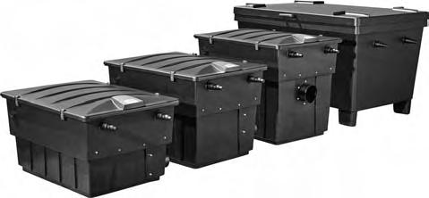
15 3 Product Description 3.1 Unit configuration A ScreenMatic rotating screen unit 1 Control device 2 Operating panel 3 Sensor underneath the control device When the sensor comes into contact with the water on the ScreenMatic screen, an automatic cleaning process is triggered. 4 Stripper scrapes the debris from the ScreenMatic screen and conveys it into the debris tray. 5 ScreenMatic screen 6 "Max. water jet" mark Debris may be washed out of the debris collection tray if the water jet from the water distributor exceeds this mark. 7 Transformer Voltage supply for the control device and motor 8 Motor Drive of the ScreenMatic rotating screen unit - EN - B, C, D BioTec ScreenMatic² 40000/60000/ Inlets, 2 x 2 Water distributor 3 Distributor extension 4 Brush for regularly cleaning the ScreenMatic screen 5 Substrate tube BioTec ScreenMatic² 40000: BioTec ScreenMatic² 60000: BioTec ScreenMatic² 90000: BioTec ScreenMatic² : 2 x 3 x 4 x 12 x 6 Separating plate can be removed from the BioTec ScreenMatic² 40000/60000/90000 for maintenance purposes. 7 Foam filter BioTec ScreenMatic² 40000/60000: BioTec ScreenMatic² 90000: BioTec ScreenMatic² : 8 x 16 x 18 x 8 Blind plug for closing the outlet (14) Closing the outlet before cleaning the foam filters prevents dirty water from flowing back into the pond. 9 Dirt outlet 10 Foam cleaning device 11 Holder for the foam cleaning device 12 Dirt outlet slide valve 13 Debris tray 14 Outlet 3.2 Properties High performance flow-through filter for ponds up to 40 m 3, 60 m 3, 90 m 3 or 140 m 3. Electrically driven ScreenMatic rotating screen for automatic removal of coarse debris. Low-maintenance filter due to the automatic removal of coarse debris. Bottom dirt outlet with slide valve for removal of dirt/debris from the filter system. Convenient cleaning of the foam filters directly inside the filter. Foam cleaning device and holder for fastening the foam cleaning device to the container. Perfectly tailored to the OASE AquaMax Eco filter pumps. Direct connection of the OASE UVC clarifiers of the Vitronic 18W/24W/36W, Bitron C and Bitron Eco series possible. Use of different filter media to ensure optimum colonisation of bacteria for biological filtration. 3.3 Intended use BioTec ScreenMatic² 40000/60000/140000, referred to as "unit", may only be used as specified in the following: For cleaning garden ponds. Operation under observance of the technical data. 3.4 Possible incorrect use The following restrictions apply to the unit: Only operate with water at a water temperature of +4 C to +35 C. 31
16 - EN - Never use the unit to convey fluids other than water. Do not use for commercial or industrial purposes. Not suitable for salt water. Do not use in conjunction with chemicals, foodstuff, easily flammable or explosive substances. 3.5 Accessing the unit Remove the container cover: Access to the control device. Hinge up the screen holder: Access to the foam filters, substrate tubes, separating plate and outlet Opening the container E BioTec ScreenMatic² 40000/60000: Release the locking clips, lift up the cover and remove. BioTec ScreenMatic² : Lift the cover using the handles and remove. Screw the handles onto the cover. The handles are not fitted on delivery. NOTE Only operate the unit with the container cover in place Hinging the screen holder up/down How to proceed: F To hinge up/open 1. Remove the debris tray. 2. Hinge up the distributor extension. 3. Hinge up the screen holder with the ScreenMatic rotating screen unit. To hinge down/close 4. Carefully hinge down the screen holder. 5. Push the distribution extension down until it audibly engages. 6. Replace the debris tray. 4 Installation and connection 4.1 Installation planning G WARNING Dangerous electrical voltage. Possible consequences: Death or severe injuries caused by electric shock from electrical units operated in or near water. Protective measures for accessible ponds: Only use electrical units or installations with a rated voltage of U AC 12 V or U DC 30 V in the water. Electrical installations with a rated voltage of U AC > 12 V or U DC > 30 V must be located at a distance of at least 2 m from the water. Protective measures for non-accessible ponds: Electrical installations with a rated voltage of U AC > 12 V or U DC > 30 V must be located at a distance of at least 2 m from the water. NOTE Use suitable transport and lifting aids to transport and install the unit. The unit weighs more than 25 kg. ( Technical data) 32
17 - EN - Distance from the pond Electrical components of the filter system operate with a rated voltage of U DC = 12 V. The supply voltage is supplied via an external transformer connected to the mains. Filter system with UVC clarifier fitted: The filter system and transformer must be located at a distance of at least 2 m from the water. Filter system without UVC clarifier fitted: The filter system can be installed directly next to the water. The transformer must be located at a distance of at least 2 m from the water. Optimum ambient and operating conditions Optimum operating results can be obtained with careful planning, taking the ambient conditions into account. As the filter is very heavy when filled, it must be placed on a suitable base (at least on slabs, but preferably on a poured concrete base) to prevent it from subsiding. Align the base slab horizontally. Ensure sufficient room for movement for carrying out cleaning and maintenance work. Allow the dirty water to drain out into a drain or far enough away from the pond to ensure that it cannot flow back into the pond. Do not position the inlet into the pond higher than the outlet of the filter system (e.g. above a water course or waterfall). 4.2 Connecting the inlet NOTE A water course or waterfall guarantees optimum water return to the pond. In this way, the filtered pond water is enriched with oxygen before it is returned to the pond. The filter system has two inlets with stepped hose adapters. For connecting a filter pump For connecting a UVC clarifier ( Connecting a UVC clarifier) If an inlet is not used, fit a closed stepped hose adapter. The stepped hose adapters are delivered closed. Prerequisite: The container is open. ( Opening the container) The screen holder is hinged up. ( Hinging the screen holder up/down) How to proceed: H 1. Shorten the stepped hose adapter to the diameter of the hose used. This reduces pressure losses. 2. Insert the stepped hose adapter with flat seal into the inlet opening. 3. Screw the distributor nut with O ring onto the stepped hose adapter and hand tighten. BioTec ScreenMatic² : Alternatively fit a 50 mm (2") hose connector. 4. Slip the hose clip over the hose, fit the hose onto the hose connector and secure with the hose clip. 4.3 Connecting a UVC clarifier Prerequisite: The container is open. ( Opening the container) The screen holder is hinged up. ( Hinging the screen holder up/down) How to proceed: I 1. Fit the UVC clarifier with flat seal into the inlet opening. 2. Screw the distributor nut with O ring onto the stepped hose adapter and hand tighten. Read the UVC clarifier operating instructions. 4.4 Connecting the outlet Use suitable pipes. Do not use any right-angled bends. Bends with a maximum angle of 45 are very efficient. 33
18 - EN - Standing water in pipes can freeze when there is a hard frost and cause pipes to burst. For this reason, lay the pipes and hoses with a gradient (50 mm/m) to ensure that they can run empty. Pipe dimensions: ( Technical data) Fitting the DN 110 outlet BioTec ScreenMatic² : The outlet is not fitted on delivery. Prerequisite: The container is open. ( Opening the container) How to proceed: J 1. Fit the O ring onto the outlet. 2. Fit the outlet into the respective hole of the container wall from the outside. Ensure that the raised marking is at the top and aligned in relation to the hole pattern. 3. Fasten the outlet from the inside with oval head screws. Tighten all screws diagonally using the cordless screwdriver to ensure that the sealing ring is uniformly applied. Further tighten the screws using a Phillips screwdriver. NOTE Build supports to increase the stability of the pipe construction and to prevent the pipe construction from sagging at the discharge. 4.5 Connecting the dirt outlet The water in the container can be drained via the dirt outlet with slide valve at the bottom of the container when required (for cleaning, repair, overwintering). Connect the pipe and drain the dirty water, for example, into a flower bed or into the sewage system. Pipe dimensions: ( Technical data) 4.6 Carry out the electrical connection How to proceed: K 1. Thread the connection cable through the opening in the container wall and seal off the opening using the sealing plug. Ensure that the connection cable inside the container is sufficiently long so that it is not subjected to tension when the ScreenMatic rotating screen unit is hinged up. Avoid tangling of the cable inside the container. 2. Connect the plug of the connection cable to the socket on the transformer and hand-tighten the union nut. 34
19 - EN - 5 Commissioning/start-up NOTE Remove the protective film from the substrate tubes and insert the substrate tubes into the container. ( Cleaning/replacing the substrate tubes) The substrate tubes are sealed in protective film on delivery. Thoroughly clean the pond before starting up the filter system for the first time to ensure that the filter system is not overloaded by excessively soiled water. OASE recommends using the PondoVac pond vacuum cleaner for cleaning the pond. This cleaning measure is normally not necessary for newly installed ponds. It is necessary to operate the filter system for 24 hours a day during the pond season. 5.1 Biological filter starter The foam filters take several weeks to reach their full biological cleaning effect. We recommend using the OASE filter starter Biokick to ensure fast growth of bacterial populations. Micro-organisms colonise the filter system, multiply and ensure an enhanced quality of the pond water by the decomposition of excess nutrients. NOTE When using filter starter, medicines or pond water treatments, leave the UVC clarifying unit switched off for at least 36 hours so as not to impair their efficacy. 5.2 Order of starting up steps How to proceed: 1. Close the slide valve of the dirt outlet. 2. Check that the filter system (pipes and hoses) is complete. 3. Remove the container cover. 4. Connect the transformer for the control device to the power supply. 5. Switch on the filter pump and UVC clarifier (if applicable). Ensure that the water is returned to the pond via the return pipe. 6. Check all pipes, hoses and their connections for leaks. Expansion seals may leak initially until they have fully expanded on contact with water. 7. Adjust the control device to the flow rate if necessary. ( Aligning the control device) 8. Check the function of the ScreenMatic rotating screen unit. ( Operation) 9. Fit the container cover. NOTE The final water level is not reached in the container until the bacteria are established and the filter becomes fully effective. New foam filters take 3 to 4 weeks to reach their full biological cleaning effect. The water level is initially lower; the foam filters are not completely covered by the water. The filter may overflow while the beneficial bacteria colonies are being established. Do not clean the foam filters for 3 to 4 weeks. The biological cleaning effect ceases at temperatures under 10 C. The filter may overflow. Cleaning is not necessary. NOTE The substrate tubes should remain completely under water to ensure maximum effectiveness. Depending on the system configuration, the level of the water in the container may be too low for this. In this case, place the top substrate tube directly into the pond at a point where there is good water circulation. 5.3 Aligning the control device Do not align the control device until after the running-in period Lowering the pump into the pond may swirl up so much debris that starting up the filter system straight away could cause the ScreenMatic screen to overflow. The filter system requires a running-in period of 2 to 3 hours. After this, the control device can be aligned if necessary. 35
20 - EN - Align the control device such that the sensor only switches when a well-formed line of debris has formed on the screen. A well-formed line of debris can be optimally removed by the stripper and conveyed into the debris tray. The stripper brush under the ScreenMatic screen collects the fine debris, which falls into the debris tray. How to proceed: L 1. Remove the screw from the control device and take out the control device. 2. Insert the control device into the determined position, insert the screw and hand tighten. Aligning the control device depending on the degree of soiling of the pond In order to prevent premature soiling of the foam filters, ensure that the dirty water does not flow beyond the "Max. water jet" mark directly into the debris tray. Do not change the position of the control device unless the water flows as far as or beyond the "Max. water jet" mark, even when the ScreenMatic screen has been cleaned (with the enclosed brush). ( Cleaning/replacing the ScreenMatic screen) Typical position of the control device BioTec ScreenMatic² BioTec ScreenMatic² BioTec ScreenMatic² BioTec ScreenMatic² <6000 l/h <7 <8000 l/h <9 <9000 l/h <10 <12000 l/h <18 >8000 l/h >7 >9000 l/h >9 >11000 l/h >10 >15000 l/h >18 Delivery state 7 Delivery state 9 Delivery state 10 Delivery state 18 6 Operation 6.1 Operating panel BTC LED, 2 colours Lit green The ScreenMatic rotating screen unit is operational Flashes green Cleaning active Flashes green/red Malfunction ( System messages) Flashes red Malfunction ( System messages) 2 Button, start/stop manual cleaning ( Manual cleaning) 6.2 Manual cleaning Proceed as follows Press for 1 s. Description The ScreenMatic screen is rotated by 1 revolution. Press the button again for 1 s: The rotational movement stops prematurely. 36
21 6.3 Automatic cleaning - EN - Due to the build-up of debris the water level on the ScreenMatic screen also rises. When the sensor in the control device comes into contact with the water, it triggers the rotational movement of the ScreenMatic screen. By briefly moving the ScreenMatic screen back several times a larger line of debris is formed, which can be better removed by the stripper. Sequence of an automatic cleaning cycle Rotational movement of the ScreenMatic screen Normal soiling 1. Contact of the sensor with water Brief movement backward 2. Contact of the sensor with water Brief movement backward 3. Contact of the sensor with water Brief movement backward 4. Contact of the sensor with water One rotation forward The debris is conveyed into the debris tray. Heavy soiling or incorrectly aligned control device (permanently high water level on the ScreenMatic screen) 1. Contact of the sensor with water Brief movement backward, then one rotation forward The debris is conveyed into the debris tray. 6.4 Time-dependent cleaning The ScreenMatic rotating screen unit executes a cleaning cycle after a set interval depending on the ambient temperature. This ensures cleaning at regular intervals if the sensor is soiled or defective, if there is very little soiling on the screen and/or low flow rates (e.g. when the SFC of the filter pump is activated). Ambient temperature Interval Rotational movement of the ScreenMatic screen 10 C 6 hours One rotation forward 10 C 20 C 4 hours The debris is conveyed into the debris tray. 20 C 3 hours 6.5 System messages LED Malfunction Possible cause Remedy Resetting the system message Flashes green/red Flashes red Flashes green No automatic cleaning cycle within 48 hours Sensor soiled No dirty water, cleaning is not necessary Clean the sensor. Descale the sensor. No flow of water Filter pump is not operating Start up the filter pump. No water detected by the sensor 20 automatic cleaning cycles in succession ScreenMatic screen not rotating although a manual Control device incorrectly positioned Control device defective Insufficient conductivity of the water Insufficient pump capacity ScreenMatic screen soiled Sensor soiled Control device incorrectly positioned Pump capacity too high Motor cable plug not connected or incorrectly connected to the control device Correctly position the control device Replace the control device. Increase the water hardness with OptiPond Adjust the pump capacity accordingly Start manual the cleaning cycle and use a brush to clean the ScreenMatic screen on the side of the water distributor ( Manual cleaning) Clean the ScreenMatic screen from the inside if the mesh is clogged by a biofilm ( Cleaning/replacing the ScreenMatic screen) Clean the sensor. Correctly position the control device Adjust the pump capacity accordingly Connect the plug, check that it is correctly seated. Automatic reset after remedy of malfunction Automatic reset after remedy of malfunction 37
22 - EN - LED Malfunction Possible cause Remedy Resetting the system message Off cleaning cycle was triggered. ScreenMatic screen not rotating although a manual cleaning cycle was triggered. Motor defective Connection cable plug not connected or incorrectly connected to the transformer Transformer not connected to the mains voltage Transformer defective Control device defective Replace motor Connect the plug, check that it is correctly seated. Connect the transformer to the mains voltage. Replace transformer Replace the control device. 7 Remedy of faults Malfunction Possible cause Remedy No flow of water Filter pump not switched on. Switch on the filter pump, connect the power plug. Supply to filter system or return to pond blocked. Clean the supply and/or return. Water flow insufficient Hose kinked or clogged Check, clean or replace the hose if necessary. Excessive loss in the hoses due to friction Insufficient pump capacity Reduce hose length to reduce frictional loss Adjust the pump capacity accordingly Water remains cloudy Insufficient circulation of the water Adjust the pump capacity accordingly The water is extremely soiled. Too many pond animals ScreenMatic screen is clogged Foam filters soiled Optimise the circulation of the water in the pond. Remove algae and leaves from the pond. Change the water. If the water is particularly contaminated, change 30% of the water to avoid damage to the fish. Reduce number of pond animals Guide value: approx. 600 mm fish length per 1 m 3 pond water Clean or replace the ScreenMatic screen. Clean foam filters No water at the pond inlet Pond inlet blocked Clean the pond inlet. Water level in the container too low, foam filters are not completely immersed in water. Increased noise Filter pump is not operating. The water level is initially lower when new foam filters are fitted as they have not yet been colonised by bacteria. The separating plate is missing. (Only BioTec ScreenMatic² 40000/60000/90000) Noise of water at the outlet due to insufficient aeration Start up the filter pump. It takes several weeks for the bacteria to become established and the foam filters to become fully effective. Use OASE filter starter Biokick to speed up the colonisation of bacteria. Insert the separating plate. Insert a tee into the discharge pipe with the opening pointing up for aeration. 8 Maintenance and cleaning WARNING Possible death or severe injury from hazardous electrical voltage! Prior to reaching into the water, isolate (switch off and disconnect) all units/devices used in the water. Isolate the device (disconnect from the power supply) before carrying out any work on it. Do not use aggressive cleaning agents or chemical solutions as they could attack the housing or impair the function of the unit. Recommended cleaning agent for removing stubborn limescale deposits: Pump cleaning agent PumpClean from OASE. Vinegar- and chlorine-free household cleaning agent. After cleaning, thoroughly rinse all parts in clean water. 8.1 Regular cleaning work Empty the debris tray: The cleaning cycle is dependent on the degree of soiling of the pond. Remove the debris tray. ( Hinging the screen holder up/down) 38
23 - EN - Clean the ScreenMatic screen: If the ScreenMatic screen becomes clogged, clean the ScreenMatic screen downstream of the water distributor using the brush. For this, manually activate the SceenMatic screen. ( Manual cleaning) Carry out intensive cleaning with the pump cleaning agent PumpClean from OASE: ( Cleaning/replacing the ScreenMatic screen) 8.2 Cleaning foam filters It is necessary to clean the foam filters as soon as the water exceeds the 100% mark on the separating plate. Do not use any chemical cleaning agents as they would kill the filter bacteria. Prerequisite: The filter pump is switched off. The container is open. ( Opening the container) The screen holder is hinged up. ( Hinging the screen holder up/down) BioTec ScreenMatic : Separating plate has been pulled out and the substrate tubes have been removed. ( Cleaning/replacing the substrate tubes) The water level in the container has lowered to the height of the outlet or below. How to proceed: M, N BioTec ScreenMatic /60000/90000: 1. Insert the plug into the outlet from the inside to close off the outlet. Remove the separating plate to facilitate access if applicable. 2. Switch on the filter pump until the foam filters are covered with water, then switch off the filter pump. 3. Compress all foam filters several times with the foam cleaning device. 4. Allow the dirty water to drain away. Open the dirt outlet slide valve and close it again when the container is empty. 5. Repeat steps 2 4 as required. 6. Rinse the container with clear water to remove any loosened dirt particles. To do this, first carry out step 2, then step Remove the plug from the inside of the outlet. 8. Close the dirt outlet slide valve. 9. Hinge down the screen holder ( Hinging the screen holder up/down), insert the debris tray and switch on the filter pump. O BioTec ScreenMatic : 1. Insert the plug into the outlet from the inside to close off the outlet. 2. Switch on the filter pump until the foam filters are covered with water, then switch off the filter pump. 3. Compress all foam filters several times with the foam cleaning device. 4. Allow the dirty water to drain away. Open the dirt outlet slide valve and close it again when the container is empty. 5. Repeat steps 2 4 as required. 6. Rinse the container with clear water to remove any loosened dirt particles. To do this, first carry out step 2, then step Remove the plug from the inside of the outlet. 8. Close the dirt outlet slide valve. 9. Hinge down the screen holder ( Hinging the screen holder up/down), insert the debris tray and switch on the filter pump. 8.3 Cleaning/replacing the substrate tubes The substrate tubes are filled with zeolite on delivery. OASE recommends replacing the zeolite with Phosless when the bacteria are established and the foam filters are fully effective. Prerequisite: The filter pump is switched off. The container is open. ( Opening the container) The screen holder is hinged up. ( Hinging the screen holder up/down) How to proceed: P BioTec ScreenMatic /60000: 39
24 - EN - 1. Remove the separating plate. 2. Remove the substrate tubes and clean them or replace their contents. BioTec ScreenMatic : Two substrate tubes BioTec ScreenMatic : Three substrate tubes When inserting, push the substrate tubes against the wall opposite to the outlet. Q BioTec ScreenMatic : 1. Remove the separating plate. 2. Remove the substrate tubes and clean them or replace their contents. BioTec ScreenMatic : Four substrate tubes Two substrate tubes each to the left of the outlet and two substrate tubes each to the right of the outlet. R BioTec ScreenMatic : Remove the substrate tubes individually and clean them or replace their contents. BioTec ScreenMatic : Twelve substrate tubes 8.4 Cleaning/replacing the ScreenMatic screen Prerequisite: The filter pump is switched off. The container is open. ( Opening the container) The debris tray is removed. ( Hinging the screen holder up/down) How to proceed: S 1. Remove the screw for fastening the control device, remove the control device and place it carefully to the side. If necessary, disconnect the motor cable plug from the control device. Mark the position of the control device on a side section for reassembly. 2. Take the ScreenMatic rotating screen unit out of the screen holder. Biotec ScreenMatic /60000/90000: Press the locking clips on both sides and remove the Screen- Matic rotating screen unit. Biotec ScreenMatic : Press the ScreenMatic rotating screen unit in the direction of the water distributor and remove. 3. Undo the nuts on the side section, and remove the side section and stripper. 4. Release the clamping lever and remove the ScreenMatic screen. Thoroughly clean the stripper. Thoroughly clean both sides of the ScreenMatic screen. Replace the ScreenMatic screen if necessary. Use the pump cleaning agent PumpClean from OASE. 5. Reassemble the ScreenMatic rotating screen unit in the reverse order and place it into the screen holder. When tensioning the ScreenMatic screen, ensure that the clamping lever engages. 8.5 Replacing foam filters Prerequisite: The filter pump is switched off. The container is open. ( Opening the container) The screen holder is hinged up. ( Hinging the screen holder up/down) How to proceed: T 1. Press both locking clips on the foam holder. 2. Remove the foam holder plate and foam filter. 3. Push a new foam filter onto the foam holder, fit the foam holder plate and push down until the two locking clips engage in the foam holder plate. 40 NOTE Recommendation regarding the replacement of foam filters: Only partially replace the foam filters at intervals of at least a week so as not to impair the biological cleaning action too much.
25 - EN - Never replace more than 50 % of the foam filters at any one time. 9 Storage/overwintering The unit is protected from frost: The unit can be operated as long as the water temperature does not go below +4 C. The deeper areas of the pond have a water temperature of approx. +4 C in winter and are essential for the fish. By taking the following measures it is possible to reduce the cooling effect on the water of the circulation by the filter system: Position the pump nearer to the surface of the water so that only colder water closer to the surface of the pond enters the pump. Insulate the return pipes from the filter system into the pond. Do not allow water to flow into the pond via a water course. The unit is not protected from frost: Take the unit out of operation at water temperatures below +8 C or, at the latest, when freezing temperatures are to be expected. Drain the unit as far as possible, clean thoroughly and check for damage. Empty all hoses, pipes and connections as far as possible. Leave the slide valves open. Cover the filter container to prevent the penetration of rain water. Protect pipes and slide valves that are in contact with water from frost. 10 Wear parts The following components are wear parts and are excluded from the warranty: Foam filters Substrate tubes ScreenMatic screen 11 Disposal NOTE Do not dispose of this unit with domestic waste. Render the unit unusable beforehand by cutting the cables and dispose of the unit via the return system provided for this purpose. 41
26 - EN - 12 Technical data Description BioTec ScreenMatic Power pack Primary rated voltage V AC Mains frequency Hz Secondary rated voltage V DC Permissible ambient temperature C Control device Power consumption W Permissible ambient temperature C Cable length Power pack m Control device m Foam filter Number of blue foam filters pce Number of red foam filters pce Number of purple foam filters pce Special filter pellets kg Removal of coarse dirt particles µm Permissible water temperature C Inlet Quantity pce Connection, hose mm 25, 32, 38 25, 32, 38 25, 32, 38, 50 25, 32, 38, 50 Connection, UVC clarifier G1, G1¼, G1½ G1, G1¼, G1½ G1, G1¼, G1½, G2 Bitron C 36 W /55 W / 72 W / 110 W Bitron Eco 120 W / 180 W / 240 W Vitronic 18 W / 24 W / 36 W Outlet Quantity pce G1, G1¼, G1½, G2 Connection DN 75 DN 75 DN 110 DN 110 Dirt outlet Quantity pce Connection DN 50 DN 50 DN 50 DN 75 Circulation capacity Min. l/h Maximum pond volume Max. l/h Without fish population m With fish population m Including koi carp m Dimensions Length mm Width mm Height mm Weight Without water kg Spare parts The use of original parts from OASE ensures continued safe and reliable operation of the unit. Please visit our website for spare parts drawings and spare parts. 42
BioCompact 25/50. Gebrauchsanleitung und Garantie Operating instructions and Guarantee
 Downloaded from www.watergardeningdirect.com BioCompact 25/50 DE EN Gebrauchsanleitung und Garantie Operating instructions and Guarantee A BCT0001 2 BioCompact 25/50 B BCT0002 3 C BCT0003 4 BioCompact
C. Biotec 30. Gebrauchsanweisung Directions for use Mode d emploi Gebruiksaanwijzing
 29739-06C Biotec 30 Gebrauchsanweisung Mode d emploi Gebruiksaanwijzing 1 Direction for use Product description Biotec 30 is a multi-zone filter for large ponds up to 130 m³, or up to 65 m³ for fish ponds.
77014 / Automatic Users Manual. Carefully read this entire Instruction Manual before using this product
 77014 / 65041 Submersible Water Pumps Automatic Users Manual Carefully read this entire Instruction Manual before using this product Please read these operating instructions carefully and ensure they are
FiltoSkim Operating instructions Notice d emploi Instrucciones de uso
 FiltoSkim 3000 Operating instructions Notice d emploi Instrucciones de uso REMINDER CALL 1-866-627-3435 BEFORE RETURNING TO STORE. Part Description QTY A Skimmer 1 B Debris basket 1 C Cover 1 D Adapter
IMPORTANT INSTRUCTIONS FOR OPERATION & MAINTENANCE OF
 IMPORTANT INSTRUCTIONS FOR OPERATION & MAINTENANCE OF CONVEYORS EASIKIT 300 EASIKIT 450 EASIKIT 600, 900, 1200 & 1500 The manufacturer does not accept responsibility for any loss, damage to other equipment,
Installation and operating instructions. Solar charge controller MPPT 10 A / 20 A Z Z
 Installation and operating instructions Solar charge controller MPPT 10 A / 20 A EN 1 Contents 1. About these instructions... 3 1.1 Applicability... 3 1.2 Users... 3 1.3 Description of symbols... 3 2.
SUBMERSIBLE PUMP HSE RANGE
 SUBMERSIBLE PUMP HSE RANGE OPERATION & MAINTENANCE INSTRUCTIONS 0707 SPECIFICATIONS HSE300* HSE360* Model No. HSE130* HSE200A HSE300A HSE360A HSEC400* HSE301A HSE361A Outlet Dia. (mm/inches) 32/1-1/4 38/1-1/2
HOT WASHER MODEL NO: KING 125 OPERATION & MAINTENANCE INSTRUCTIONS PART NO: LS1009
 HOT WASHER MODEL NO: KING 125 PART NO: 7320170 OPERATION & MAINTENANCE INSTRUCTIONS LS1009 INTRODUCTION Thank you for purchasing this Hot Washer. This machine is a portable, high pressure power washer,
Installation and Operating Manual for Tank and Equipment Cleaning Nozzles Series 5TM
 Installation and Operating Manual for Tank and Equipment Cleaning Nozzles Series 5TM 150 150 150 This instruction manual contains proprietary information which is protected by copyright laws. No part of
SUBMERSIBLE PUMP HSE RANGE
 SUBMERSIBLE PUMP HSE RANGE OPERATION & MAINTENANCE INSTRUCTIONS 0806 SPECIFICATIONS Model No. HSE120* HSE200 HSE300*/ HSE360*/ HSEC400* HSE301 HSE361 Outlet Dia. (mm/inches) 32/1-1/4 38/1-1/2 50/2 50/2
Operating instructions. sonnenprotect for operators. KD-337 Part no Version X00.
 Operating instructions for operators sonnenprotect 1300 KD-337 Part no. 22010 Version X00 info@sonnenbatterie.de www.sonnenbatterie.de EN IMPORTANT Read this documentation carefully before operation. Retain
SUBMERSIBLE WATER PUMP
 SUBMERSIBLE WATER PUMP MODEL No: IVP14A Part No: 7230095 OPERATION & MAINTENANCE INSTRUCTIONS 08/08 INTRODUCTION Thank you for purchasing this CLARKE water pump. This highly efficient centrifugal pump
Operating instructions ErgoPack 600 E
 Operating instructions ErgoPack 600 E Operation of the device is only permitted if the operating instructions have been carefully read and understood before use! Declaration of conformity EU declaration
Manual for 12 Sand Filter/ Pump Combo Unit.
 Manual for 12 Sand Filter/ Pump Combo Unit. MODELS: CC2013/CC2015 SAFETY INFORMATION 1. The sand filters are designed to work with water at temperature>than 0 and
SUBMERSIBLE WATER PUMPS
 SUBMERSIBLE WATER PUMPS Model Nos. CS85S - CS85SA CS120S - CS120SA CS185S - CS185SA CS240S - CS240SA CS305S - CS305SA OPERATING & MAINTENANCE INSTRUCTIONS 1000 CONTENTS Warranty conditions... 3 Safety
SUBMERSIBLE PUMP. Model No: HIPPO 2 OPERATING & MAINTENANCE INSTRUCTIONS
 SUBMERSIBLE PUMP Model No: HIPPO 2 OPERATING & MAINTENANCE INSTRUCTIONS 0107 1 HIPPO 2 240 Volt and 110 Volt models Thank you for purchasing this Clarke Hippo 2 Pump. Before attempting to operate this
Compressor Refrigerator Instruction Manual
 AKF80 Compressor Refrigerator Instruction Manual Contents Please read this operating manual carefully before starting the device. Keep it in a safe place for future reference. If the device is passed on
Installation manual portable distributors
 EN Installation manual portable distributors EN 60003206 Issue 11.2016 15/11/2016 Table of contents 1 About this manual 3 1.1 Structure of the warnings 3 1.2 Symbols used 4 1.3 Signal words used 4 2 Intended
Starting up hydraulic systems
 General / Installation A hydraulic system that operates economically, safely, and trouble-free requires careful planning, as well as proper installation and start-up. Conscientious maintenance has a considerable
Battery Charger JCB-FCH12Li
 Safety and operating manual Battery Charger JCB-FCH12Li ORIGINAL INSTRUCTIONS SAFETY INSTRUCTIONS WARNING: Read all safety warnings and all instructions.failure to follow the warnings and instructions
User Manual Digital Water Level Indicator for rain water storage tanks
 User Manual Digital Water Level Indicator for rain water storage tanks We congratulate you on the purchase of Digital Water Level measuring device. You have purchased a high-quality product built to the
SUBMERSIBLE DIRTY WATER PUMP
 FOR USE WITH A 110V SUPPLY ONLY SUBMERSIBLE DIRTY WATER PUMP MODEL NO: DWP210A PART NO: 7230102 OPERATION & MAINTENANCE INSTRUCTIONS LS0115 INTRODUCTION Thank you for purchasing this CLARKE Submersible
Installation manual wall-mounted distributor
 EN Installation manual wall-mounted distributor EN 60003233 Issue 11.2016 2016-14-11 Table of contents 1 About this manual 3 1.1 Structure of the warnings 3 1.2 Symbols used 4 1.3 Signal words used 4 2
SUBMERSIBLE WATER PUMP OPERATING & MAINTENANCE INSTRUCTIONS. Model Nos. CSE400A. Part No iss 2
 SUBMERSIBLE WATER PUMP Model Nos. CSE400A Part No. 7231100 0917 iss 2 OPERATING & MAINTENANCE INSTRUCTIONS Thank you for purchasing this Clarke Submersible Pump. This highly efficient pump is designed
Operating Instructions. International English. CCS Dust Extractor
 Operating Instructions International English CCS Dust Extractor Electric Cast Saw Dust Removal System Warnings & Safety Rules WARNING!: THIS EQUIPMENT MUST BE EARTHED! Danger!: Possible explosion hazard
1200W INVERTER GENERATOR
 1200W INVERTER GENERATOR MODEL NO: IG1200 PART NO: 8877070 OPERATION & MAINTENANCE INSTRUCTIONS LS0117 INTRODUCTION Thank you for purchasing this CLARKE 1200W Inverter Generator. Before attempting to use
OPERATION & MAINTENANCE INSTRUCTIONS
 750W SUBMERSIBLE PUMP WITH BUILT-IN FLOAT SWITCH MODEL NO: PSV5A PART NO: 7236046 OPERATION & MAINTENANCE INSTRUCTIONS ORIGINAL INSTRUCTIONS LS0917 iss 3 INTRODUCTION Thank you for purchasing this CLARKE
Car Battery Charger Instructions for Use
 BATTERY CHARGER 12Volt 4Amp FOR INDOOR USE ONLY Power Details: Input: 230-240Vac; 50Hz; 52W Output: 12V DC; 2.8A Maximum Charge Rate: 4A RMS Read these instructions before operating this car battery charger
Operating manual. original operating manual. HDA eco Box 12/24V DC Automatic Dispenser. Translation of the. Item No.:
 Operating manual HDA eco Box 12/24V DC Automatic Dispenser Item No.: 110 500 900 Translation of the original operating manual Important! Copyright The operating manual is always to be read before commissioning
Operating instructions 1 4 Mode d emploi 5 8 Instrucciones de uso 9 13 Manual de instruções 15 18
 *336376* 336376 SFC 7/18 USA CDN E P Operating instructions 1 4 Mode d emploi 5 8 Instrucciones de uso 9 13 Manual de instruções 15 18 R 1 2 UL Listed to U.S. and Canadian safety standards C US LISTED
AG-HA-2500N GASOLINE GENERATOR
 AG-HA-2500N GASOLINE GENERATOR OWNER S MANUAL BEFORE OPERATING THIS EQUIPMENT PLEASE READ THESE INSTRUCTIONS CAREFULLY (I)WARNING 1. Read the operator s instruction manual. 2. Attention! Exhaust gases
STIHL AP 100, 200, 300. Safety Precautions
 { STIHL AP 100, 200, 300 Safety Precautions English Contents Translation of Original Instruction Manual Printed on chlorine-free paper Printing inks contain vegetable oils, paper can be recycled. 1 Safety
CoolFreeze CFX35, CFX40, CFX50, CFX65, CFX65DZ
 CoolFreeze CFX35, CFX40, CFX50, CFX65, CFX65DZ EN 6 Compressor Cooler Operating manual FR 25 Glacière à compression Notice d utilisation ES 45 Nevera por compresor Instrucciones de uso 1 1 SET + 2 3 2
MODEL Nos: CVAC20SS CVAC25SS CVAC30SSR OPERATING & MAINTENANCE INSTRUCTIONS. Distributed by CLARKE International Ltd.
 MODEL Nos: CVAC20SS CVAC25SS CVAC30SSR OPERATING & MAINTENANCE INSTRUCTIONS Distributed by CLARKE International Ltd. 1006 Thank you for selecting this VAC KING Stainless Steel Vacuum Cleaner, which will
OPERATION & MAINTENANCE INSTRUCTIONS
 400W SUBMERSIBLE PUMP WITH FOLDING BASE AND FLOAT SWITCH MODEL NO: PSV6A PART NO: 7230695 OPERATION & MAINTENANCE INSTRUCTIONS LS0315 INTRODUCTION Thank you for purchasing this CLARKE 400W Submersible
VADA - V60-J PRODUCT OVERVIEW CONSTRUCTION MOTOR USAGE LIMITATIONS WARRANTY
 PRODUCT OVERVIEW The VADA series of self priming jet pumps combine the functional benefits of centrifugal pumps and the practical and qualitative benefits of self-priming pumps. The Venturi system the
Anleitung_BG_PW_48_SPK1:_ :33 Uhr Seite 1. Operating Instructions Petrol Water Pump. Art.-Nr.: I.-Nr.
 Anleitung_BG_PW_48_SPK1:_ 25.06.2008 9:33 Uhr Seite 1 Operating Instructions Petrol Water Pump Art.-Nr.: 41.713.43 I.-Nr.: 11010 BG-PW 48 Anleitung_BG_PW_48_SPK1:_ 25.06.2008 9:33 Uhr Seite 2 Read and
VADA - V75-S PRODUCT OVERVIEW CONSTRUCTION USAGE LIMITATIONS MOTOR WARRANTY
 PRODUCT OVERVIEW The VADA V75-S submersible pumps are suitable for installation in traditional wells, water deposits, collection tanks, clear watercourses, lakes etc. The V75-S provides a hydraulic system
FL 10 DIAPHRAGM PUMP INSTALLATION INSTRUCTIONS. Before operating the pump, please read the Installation Instructions and safety precautions.
 FL 10 INSTALLATION INSTRUCTIONS DIAPHRAGM PUMP FL 10 DC-P FL 10 AC Before operating the pump, please read the Installation Instructions and safety precautions. Installation Instructions FL 10 Table of
Battery Charger JCB- SCH20LI.2
 Safety and operating manual Battery Charger JCB- SCH20LI.2 ORIGINAL INSTRUCTIONS SAFETY INSTRUCTIONS WARNING: Read all safety warnings and all instructions.failure to follow the warnings and instructions
HIGH FREQUENCY AUTOMATIC BATTERY CHARGER
 HIGH FREQUENCY AUTOMATIC BATTERY CHARGER MODEL NO: HFBC12 PART NO: 6267000 OPERATION & MAINTENANCE INSTRUCTIONS LS0814 INTRODUCTION Thank you for purchasing this CLARKE High Frequency Automatic Battery
SUBMERSIBLE PUMPS HSE RANGE OPERATING & MAINTENANCE INSTRUCTIONS GC0514
 SUBMERSIBLE PUMPS HSE RANGE OPERATING & MAINTENANCE INSTRUCTIONS GC0514 INTRODUCTION Thank you for purchasing this CLARKE submersible pump. Before attempting to use the pump, please read this manual thoroughly
C3 Operating Instructions
 Version 3.1 Stand 09.2014 Robert Bosch (Australia) Pty. Ltd. 1555 Centre Road Clayton, Victoria 3168 C3 Operating Instructions For further information please contact Bosch at: Australia 1300 30 70 40 www.boschautoparts.com.au
ENGINE DRIVEN 3 FULL TRASH PUMP
 ENGINE DRIVEN 3 FULL TRASH PUMP MODEL NO: PF75 PART NO: 7230165 OPERATION & MAINTENANCE INSTRUCTIONS ORIGINAL INSTRUCTIONS LS0117 ISS 2 INTRODUCTION Thank you for choosing this Clarke Pump. The function
QUICK START GUIDE OWNER S MANUAL AL50 SERIES SAND FILTRATION TECHNOLOGY PLEASE CALL DO NOT RETURN TO STORE
 QUICK START GUIDE OWNER S MANUAL SAFETY, INSTALLATION, OPERATION & PARTS AL50 SERIES SAND FILTRATION TECHNOLOGY PLEASE CALL 877-278-2797 DO NOT RETURN TO STORE! WARNING This equipment must be installed
2 TONNE TROLLEY JACK
 2 TONNE TROLLEY JACK 61829 IMPORTANT: Please read these instructions carefully to ensure the safe and effective use of this product and save these instructions for future reference. This manual has been
Diaphragm Vacuum Pumps and Compressors
 Operating Instructions Read and observe these Operating Instructions! Diaphragm Vacuum Pumps and Compressors N145 AN.18 N145 AT.18 N145 AV.18 N145.1.2 AN.18 N145.1.2 AT.18 N145.1.2 AV.18 KNF Neuberger
250W PUDDLE PUMP WITH AUTO SENSOR MODEL NO: PSP105
 250W PUDDLE PUMP WITH AUTO SENSOR MODEL NO: PSP105 PART NO: 7230693 OPERATION & MAINTENANCE INSTRUCTIONS ORIGINAL INSTRUCTIONS LS0917 -- iss 3 INTRODUCTION Thank you for purchasing this CLARKE 250W Puddle
Drive Unit e-drive1. Installation instructions 04/2014. English translation of the original German installation instructions
 Drive Unit e-drive1 Installation instructions 04/2014 English translation of the original German installation instructions Contents Foreword... 3 Availability... 3 Structural features in the text... 3
FF 20 DIAPHRAGM PUMP INSTALLATION INSTRUCTIONS
 FF 20 INSTALLATION INSTRUCTIONS DIAPHRAGM PUMP FF 20 DCB-4 FF 20 DC-M Before operating the pump and the accessories, please read the Installation Instructions and safety precautions. Installation Instructions
BATHTUBS & WHIRLPOOLS BATHTUB DIVINA
 BATHTUBS & WHIRLPOOLS BATHTUB DIVINA GB INSTALLATION INSTRUCTIONS 01.008.0 MPORTANT INSTRUCTIONS! Before installation, please check to make sure the product has not been damaged during transportation.
Porte 150 Users Manual Swing Gate Opener 24V DC
 Porte 150 Users Manual Swing Gate Opener 24V DC for residential use only Signal Light Push-button Control Box 14 Contents 1. Important Safety Information 2. Product Description and Application 2.1 Application
Instructions for use and installation Cooker Hood
 Instructions for use and installation Cooker Hood FTU 3807 WXS 70H FTU 3807-P WXS 70H Instructions Manual INDEX RECOMMENDATIONS AND SUGGESTIONS...18 CHARACTERISTICS...19 INSTALLATION...20 USE...24 MAINTENANCE...25
Pressurized Bead Filters
 Pressurized Bead Filters Installation Instructions Table of Contents Safety Information Installation Assembly Start Up Maintenance Troubleshooting Warranty Safety Information: 1. Installation should be
3 TONNE TROLLEY JACK
 3 TONNE TROLLEY JACK 16407 These instructions accompanying the product are the original instructions. This document is part of the product, keep it for the life of the product passing it on to any subsequent
Jacuzzi. J-SF24 Media Filter Installation and Operating Instructions
 Jacuzzi J-SF24 Media Filter Installation and Operating Instructions GENERAL NOTES 1. When unpacking the Jacuzzi J-SF24 filter, be sure the unit is complete and no visible shipping damage has occurred.
SUBMERSIBLE WATER PUMP
 SUBMERSIBLE WATER PUMP MODEL NO: CSV1A, CSV2A PART NO: 7230582, 7230602 OPERATION & MAINTENANCE INSTRUCTIONS ORIGINAL INSTRUCTIONS 05/14 iss 4 INTRODUCTION Thank you for purchasing this CLARKE Submersible
Battery Charger JCB-FCH20LI2
 Safety and operating manual Battery Charger JCB-FCH20LI2 ORIGINAL INSTRUCTIONS SAFETY INSTRUCTIONS WARNING: Read all safety warnings and all instructions.failure to follow the warnings and instructions
DYNAFLUID 2000 STEAM & WATER MIXING VALVE INSTALLATION & OPERATING MANUAL
 DYNAFLUID 2000 STEAM & WATER MIXING VALVE INSTALLATION & OPERATING MANUAL LILLY ENGINEERING COMPANY 217 CATALPA STREET P.O. BOX 173 ITASCA, ILLINOIS 60143 630-773-2222 FAX: 630-773-3443 www.lillyengineering.com
Operating instructions Flow monitors SI5002 SI5003 SI / / 2012
 Operating instructions Flow monitors SI5002 SI5003 SI0521 704318 / 03 08 / 2012 Contents 1 Safety instructions... 3 2 Functions and features... 4 2.1 Application area... 4 2.2 Operating principle flow
Diaphragm Vacuum Pumps and Compressors
 Operating Instructions Read and observe these Operating Instructions! Diaphragm Vacuum Pumps and Compressors N022 AN.18 N022 AT.18 N022 AV.18 N026.1.2 AN.18 N026.1.2 AT.18 N026.1.2 AV.18 N026.3 AN.18 N026.3
garden PUMP kit 1 Depth A & B must be less than 9m Max Depth C must be less than 9m Max GardenPump Inst 6/11/07 12:52 Page 1
 33801-001 GardenPump Inst 6/11/07 12:52 Page 1 2823 7816 7819 garden PUMP kit 1 Depth A & B must be less than 9m Max B A 2 Depth C must be less than 9m Max C Hozelock Ltd. Midpoint Park, Birmingham B76
Domestic Water Supply Pressure Pumps
 Domestic Water Supply Pressure Pumps Bianco Domestic Water Supply Pressure Pumps BIA-MULTI900PC BIA-MULTI1300 Instruction manual Safety precautions The symbol together with one of the following words Danger
Assembly and Maintenance Manual Type ASNU
 Assembly and Maintenance Manual Type ASNU Hatschekstr.36 69126 Heidelberg Germany Tel +49(0)6221 30470 Fax +49(0)6221 304731 info@stieber.de www.stieber.de Date of issue: 30.05.2018 GB Revision: 0 U:\EngUsers\!ProduktDoku\1AAA_Einbauerklaerung_Wartungsanleitung_Konformitaetserklaerung\1AAA_Wartungsanleitungen\Orginal_Worddatei\_ASNU.docx
MP V 8A Electronic Smart Charger. Instruction and Information Manual
 MP7428 12V 8A Electronic Smart Charger Instruction and Information Manual In order to ensure correct and safe usage of your battery charger, you should read these instructions carefully. Please retain
Unilift KP 150, KP 250, KP 350
 GRUNDFOS INSTRUCTIONS Unilift KP 150, KP 250, KP 350 Installation and operating instructions DRAINAGE PUMP 1Z28 LIMITED WARRANTY Products manufactured by GRUNDFOS PUMPS CORPORATION (Grundfos) are warranted
AQUATEC R / AQUATEC F / AQUATEC XL. Bathlift Operating instructions
 AQUATEC R / AQUATEC F / AQUATEC XL Bathlift Operating instructions 1 2 3 4 5 6 7 8 9 10 11 Contents 1 General instructions................. 3 1.1 Introduction......................... 3 1.2 Proper use.........................
Cordless Rechargeable Saw Instructions for Use
 Technical data Voltage: DC 10.8V Weight: 1.25Kg Stroke rate: 0-2100/min Stroke: 15mm Cutting capacity: max diameter in wood 80mm / in soft metal 7mm Charging time: Between 5.0-5.5 Hours Battery: 1.3Ah
Operating instructions in the back. PD1420LP
 Operating instructions in the back www.blackanddecker.co.uk PD1420LP 2 ENGLISH (Original instructions) Intended use Your Black & Decker Dustbuster handheld vacuum cleaner has been designed for vacuum cleaning
Wilo-Control SC-Fire Jockey
 Pioneering for You Wilo-Control SC-Fire Jockey de en fr Einbau- und Betriebsanleitung Installation and operating instructions Notice de montage et de mise en service nl Inbouw- en bedieningsvoorschriften
18V CORDLESS STAPLER/NAILER
 18V CORDLESS STAPLER/NAILER MODEL NO: CONSN18LI PART NO: 6487055 OPERATION & MAINTENANCE INSTRUCTIONS LS1213 INTRODUCTION Thank you for purchasing this CLARKE product. Before attempting to use this product,
H-1274 OR-T 200. Battery-hand tool for plastic strapping. Before using the tool, read the operating instructions carefully. 08/07
 H- OR-T 00 Battery-hand tool for plastic strapping Before using the tool, read the operating instructions carefully. 08/0 ORGAPACK OR-T 00 Technical data TABLE OF CONTENTS General information Page. Information
Operating instructions Accu Jet
 Operating instructions Accu Jet Keep for future use! Ident number: 04.8800.000 Air Line Table of contents 1 Scope of delivery... 4 2 Operator instructions... 5 3 Safety... 6 3.1 Intended use...8 4 Description
Operating and Installation Instructions Swing Piston Compressors and Vacuum Pumps
 Operating and Installation Instructions Swing Piston Compressors and Vacuum Pumps UNPK04DC Pressure UNPK04DCB Pressure UNPK04DC Vacuum UNPK04DCB Vacuum KNF Neuberger, Inc 2 Black Forest Rd Trenton, NJ
1/2 HP SUMP PUMP OWNER'S MANUAL
 TM 1/2 HP SUMP PUMP OWNER'S MANUAL WARNING: Read carefully and understand all INSTRUCTIONS before operating. Failure to follow the safety rules and other basic safety precautions may result in serious
Operating instructions in the back. PD1820LF
 Operating instructions in the back www.blackanddecker.co.uk PD1820LF 2 ENGLISH (Original instructions) Intended use Your BLACK+DECKER Dustbuster handheld vacuum cleaner has been designed for vacuum cleaning
OPERATING AND MAINTENANCE INSTRUCTIONS HYDRAULIC ELECTRICAL PUMPS HAM (Manual control) HAE (Electrical control)
 HAE (Electrical control)") OPERATING AND MAINTENANCE INSTRUCTIONS HYDRAULIC ELECTRICAL PUMPS HAM (Manual control) HAE (Electrical control) Part Nr : HA M 4 6 2 1 B C 1. Essential safety requirements. 2. Technical Characteristics.
OPERATING AND MAINTENANCE INSTRUCTIONS HYDRAULIC ELECTRICAL PUMPS HAM (Manual control) HAE (Electrical control) Part Nr : HA M 4 6 2 1 B C 1. Essential safety requirements. 2. Technical Characteristics.
INSTALLATION AND OPERATING INSTRUCTIONS
 INSTALLATION AND OPERATING INSTRUCTIONS MF21 & 25 SERIES FILTER MF28 SERIES FILTER 28/03/2018 MF SERIES MEDIA FILTERS Dimensions With Valve Installed Model Height Width Shipping Weight MF21 MF25 MF28 98
Operating instructions Flow monitor SI / / 2013
 Operating instructions Flow monitor SI0558 706335 / 00 03 / 2013 Contents 1 Preliminary note...3 1.1 Explanation of symbols...3 2 Safety instructions...3 3 Functions and features...4 3.1 Applications...4
Operating Instructions
 Operating Instructions Ex UPS Combination of > 8265/5 GUBox control panel > 8316 battery box Contents 1 Contents 1 Contents 2 2 General Information 2 3 Safety Instructions 2 4 Conformity to standards 3
Operating and Installation Instructions
 Operating and Installation Instructions Industrial two-leaf fence gate Operating and Maintenance Manual Last Update - 20th October, 2003 GB 1. IMPORTANT INFORMATION The gate can be installed only by a
Level Measuring Sensor for Diesel Fuel Tanks
 Installation and Operating Manual Level Measuring Sensor for Diesel Fuel Tanks Executions with switchable output voltage signal: 0-2.3 V and industrial standard signal 0-10 V: Tank Sensor Diesel 010-250
OWNERS MANUAL ECODIVER
 OWNERS MANUAL ECODIVER ECO-DIVER Powerful multistage submersible pumps ideal for rain water systems, operating sprinklers, pumping water from tanks, cisterns, ponds and wells and other applications that
2.0Ah BATTERY INSTRUCTION MANUAL
 BATTERY SAFETY WARNINGS THIS MANUAL CONTAINS IMPORTANT SAFETY AND OPERATING INSTRUCTIONS FOR YOUR BATTERY. 2.0Ah BATTERY INSTRUCTION MANUAL SPECIFICATIONS Input: Battery Capacity: Power Consumption: Weight:
Sand Filtration System
 Sand Filtration System Owners Manual Installation, Operation, and Parts SHOW FILTRATION SYSTEM SAVE THIS INSTRUCTION MANUAL Note: Use only High Rate Sand No. 20 Silica Sand (.45mm -.55) specifically manufactured
KeContact P20. User manual
 KeContact P20 User manual Comments to this manual In this manual you will find warnings against possible dangerous situations. The used symbols apply to the following meanings:!! WARNING! Indicates a potentially
Assembly and Maintenance Manual Type AS
 Assembly and Maintenance Manual Type AS Hatschekstr.36 69126 Heidelberg Germany Tel +49(0)6221 30470 Fax +49(0)6221 304731 info@stieber.de www.stieber.de Date of issue: 30.05.2018 GB Revision: 0 U:\EngUsers\!ProduktDoku\1AAA_Einbauerklaerung_Wartungsanleitung_Konformitaetserklaerung\1AAA_Wartungsanleitungen\Orginal_Worddatei\_AS.docx
1100W PORTABLE GENERATOR
 1100W PORTABLE GENERATOR MODEL NO: G1200 PART NO: 8010110 OPERATION & MAINTENANCE INSTRUCTIONS LS0312 INTRODUCTION Thank you for purchasing this CLARKE 1100W Portable Generator. Before attempting to use
INSTALLATION AND OPERATING INSTRUCTIONS
 INSTALLATION AND OPERATING INSTRUCTIONS I INSTALLATION AND OPERATING INSTRUCTIONS CA & ECA Series MEDIA Filters Bolero ND Cleaner INSTALLATION AND OPERATING INSTRUCTIONS ECA SERIES FILTER CA SERIES FILTER
GRUNDFOS ALLDOS INSTRUCTIONS. DMB dosing pump. Installation and operating instructions (basic version)
") GRUNDFOS ALLDOS INSTRUCTIONS DMB dosing pump Installation and operating instructions (basic version) 1 CONTENTS 1. General information...3 1.1 Applications...3 1.2 Service documentation...3 1.3 Operating
GRUNDFOS ALLDOS INSTRUCTIONS DMB dosing pump Installation and operating instructions (basic version) 1 CONTENTS 1. General information...3 1.1 Applications...3 1.2 Service documentation...3 1.3 Operating
OPERATION & MAINTENANCE INSTRUCTIONS
 WARNING Read the instructions before using the machine PETROL DRIVEN POWER WASHER MODEL NO: TIGER1700 PART NO: 7320054 OPERATION & MAINTENANCE INSTRUCTIONS LS0511 2 INTRODUCTION Thank you for purchasing
Matala. VersiFlow Series. Instruction and Maintenance Manual
 VersiFlow Series High Flow Multi-Purpose "Versatile " Pump V-3200 1/5HP 150W / Discharge 2 V-3900 1/3HP 250W / Discharge 2 V-4700 1/2HP 400W / Discharge 2 V-5600 1HP 750W / Discharge 2 Instruction and
CORDLESS WORK LIGHT CORDLESS WORK LIGHT. Operation and Safety Notes IAN
 CORDLESS WORK LIGHT CORDLESS WORK LIGHT Operation and Safety Notes IAN 288518 GB / IE / NI Operation and Safety Notes Page 5 A HG01386A-BS 5 1 2 6 3 4 7 8 10 9 B C 11 12 13 List of pictograms used...page
Owners Manual: - Pumps
 Owners Manual: - Pumps GENERAL SAFETY RULES 1. The products mentioned in this manual are specially designed for the pre-filtering and re-circulation of water in swimming pools and spas. 2. They are designed
Operating Instructions
 Operating Instructions BE2700 Brinkmann Immersions pumps of the series TA/STA/TAL/SAL901... 1303 Contents 1 General...1 2 Safety...2 3 Transport and storage...2 4 Description of product and accessories...2
c-go 12V/10A 12V/20A Power supply and battery charger Instruction manual
 c-go 12V/10A 12V/20A Power supply and battery charger GB Instruction manual 1 Index 1. Product description... 2 2. Safety advices... 3 3. Mounting and installation... 4 4. Operation... 5 5. Problem solving...
MTD OHV Series I15 FORM NO I. MTD Products Aktiengesellschaft Saarbrücken Germany
 MTD OHV Series I15 FORM NO. 769-01577I MTD Products Aktiengesellschaft Saarbrücken Germany 8 15 23 31 38 46 54 61 68 75 82 90 99 107 115 122 130 138 145 152 159 166 175 183 193 202 211 218 226 English
Pressure relief valve
 Pressure relief valve Operating manual Series DHV 712 Version BA-2015.10.20 EN Print-No. 300 510 TR MA DE Rev001 ASV Stübbe GmbH & Co. KG Hollwieser Straße 5 32602 Vlotho Germany Phone: +49 (0) 5733-799-0
Installation and Operating Instructions. Gravity Band Filter Typ PF
 Installation and Operating Instructions Gravity Band Filter Typ PF GB Table of contents Page 1 Description of product and function... 5 2 Safety instructions... 6 2.1 General instructions... 6 2.2 Instructions
230V DIESEL FUEL TRANSFER PUMP MODEL NO: DFT230
 230V DIESEL FUEL TRANSFER PUMP MODEL NO: DFT230 PART NO: 7160050 OPERATION & MAINTENANCE INSTRUCTIONS GC0816 INTRODUCTION Thank you for purchasing this CLARKE Pump. The DFTP230 pump is a self-priming rotary