BE 46 COMBINATION METER PARTS LOCATION
|
|
|
- Morris Shepherd
- 6 years ago
- Views:
Transcription
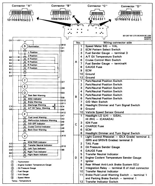
1 BE46 PARTS LOCATION

2 METER CIRCUIT w/o Tachometer BE47
3 BE48 w/ Tachometer
4 TROUBLESHOOTING The table below will be useful for you in troubleshooting these electrical problems. The most likely causes of the malfunction are shown in the order of their probability. Inspect each part in the order shown, and replace the part when it is found to be faulty. ÑÑÑÑÑÑÑÑ Trouble ÑÑÑÑÑÑÑ Parts name (See page) ÑÑÑ 1. GAUGE Fuse (BE11) Gauges and Indicator Lights do not operate ÑÑÑ 2. Wire Harness ÑÑÑ 1. Volt Gauge (BE52) Voltmeter does not work ÑÑÑ 2. Wire Harness ÑÑÑ 1. Tachometer (BE51) Tachometer does not operate ÑÑÑ 2. Wire Harness ÑÑÑ 1. Receiver Gauge (BE52) ÑÑÑÑÑÑÑÑ Fuel Gauge does not operate ÑÑÑÑÑÑÑ 2. Sender Gauge (BE53) ÑÑÑ 3. Wire Harness ÑÑÑÑÑÑÑÑ Engine Coolant Temperature Gauge does not operate ÑÑÑÑÑÑÑ 1. Receiver Gauge (BE55) ÑÑÑ 2. Wire Harness ÑÑÑ 1. Receiver Gauge (BE57) Oil Pressure Gauge does not operate 2. Sender Gauge (BE58) ÑÑÑ 3. Wire Harness ÑÑÑ 1. Bulb Burned Out ÑÑÑ 2. Brake Fluid Level Warning Switch (BE58) ÑÑÑÑÑÑÑÑ Brake Warning Light does not Light up ÑÑÑÑÑÑÑ 3. Parking Brake Switch (BE58) ÑÑÑ 4. Wire Harness ÑÑÑ 1. Bulb Burned Out ÑÑÑÑÑÑÑÑ Seat Belt Warning Light does not Light up ÑÑÑÑÑÑÑ 2. Integration Relay (BE60) ÑÑÑ 3. Wire Harness ÑÑÑ 1. IGN Fuse (BE11) ÑÑÑ 2. CHARGE Fuse (BE11) Discharge Warning Light does not Light Up ÑÑÑ 3. Bulb Burned out ÑÑÑ 4. Wire Harness BE49
5 BE50 SPEEDOMETER INSPECT SPEEDOMETER (ONVEHICLE) (a) Using a speedometer tester inspect the speedometer for allowable indication error and check the operation of the odometer. HINT: Tire wear and tire over or under inflation will increase the indication error. If error is excessive, replace the speedometer. (b) Check the speedometer for pointer vibration and abnormal noise. km / h Standard indication Allowable range 20 (1724) Ñ Ñ Ñ Ñ Ñ Ñ Ñ mph Ñ Standard indication Allowable range Ñ Ñ Ñ Ñ Ñ
6 BE51 VEHICLE SPEED SENSOR INSPECT VEHICLE SPEED SENSOR (a) Connect the positive (+) lead from battery to terminal 1 and negative () lead to terminal 2. (b) Connect the positive (+) lead from tester to terminal 3 and negative () lead to terminal 2. (c) Revolve shaft. (d) Check that there is voltage change from approx. 0 V to 11 V or more between terminal 3 and 2. HINT: The voltage change should be 4 times per each revolution of the speed sensor shaft. If operation is not as specified, replace the sensor. TACHOMETER INSPECT TACHOMETER (ONVEHICLE) (a) Connect a tuneup test tachometer, and start the engine. NOTICE: Reversing the connection of the tachometer will damage the transistors and diodes inside. When removing or installing the tachometer, be careful not to drop or subject it to heavy shocks. (b) Compare the tester and tachometer indications. DC 13.5V 20 C at (68 F) Standard indication (RPM) Ñ Allowable range (RPM) 700 Ñ ,000 Ñ 2,8503,150 5,000 4,8505,150 7,000 6,7907,210 If error is excessive, replace the tachometer.
 Disconnect the connector from the sender gauge. (b) Turn the ignition switch ON, check that the receiver gauge needle indicates EMPTY.")
7 BE52 VOLT GAUGE INSPECT VOLT GAUGE Measure the resistance between terminals A and B. Resistance: Approx. 347 If resistance value is not as specified, replace the gauge. FUEL RECEIVER GAUGE INSPECT FUEL RECEIVER GAUGE Operation (a) Disconnect the connector from the sender gauge. (b) Turn the ignition switch ON, check that the receiver gauge needle indicates EMPTY. (c) Connect terminals 1 and 2 on the wire harness side connector through a 3.4 W test bulb. (d) Turn the ignition switch ON, check that the bulb lights up and the receiver gauge needle moves towards the full side. HINT: w/ Tachometer Because of the silicon oil in the gauge, it will take a short time for the needle to stabilize. If operation is not as specified, inspect the receiver gauge resistance, and the voltage regulator (w/o Tachometer). Voltage Regulator: w/o Tachometer (a) Connect the positive (+) lead from the battery to terminal A and negative () lead to terminal B. (b) Connect the positive (+) lead from the voltmeter to terminal C and the negative () lead to terminal B and check that the voltmeter needle vibrates near the 7 V position. If voltage value is not as specified, replace the receiver gauge.
8 BE53 Resistance Measure the resistance between terminals. w/o Tachometer ÑÑÑÑÑÑÑÑÑ ÑÑÑÑÑÑÑÑÑÑ Between terminals Resistance ( ) ÑÑÑÑÑÑÑÑÑÑ AB Approx. 55 ÑÑÑÑÑÑÑÑÑÑ AC ÑÑÑÑÑÑÑÑÑÑ BC If resistance value is not as specified, replace the receiver gauge. w/ Tachometer ÑÑÑÑÑÑÑÑÑ Between terminals Resistance ( ) ÑÑÑÑÑÑÑÑÑ ÑÑÑÑÑÑÑÑÑÑ AB Approx. 123 ÑÑÑÑÑÑÑÑÑÑ AC Approx. 260 ÑÑÑÑÑÑÑÑÑÑ BC Approx. 137 If resistance value is not as specified, replace the receiver gauge. FUEL SENDER GAUGE INSPECT FUEL SENDER GAUGE Operation (a) Connect a series of three 1.5 V dry cell batteries. (b) Connect the positive (+) lead from the dry cell batteries to terminal 2 through a 3.4 W test bulb and the negative () lead to terminal 1. (c) Connect the positive (+) lead from the voltmeter to terminal 2 and the negative () lead to terminal 1. (d) Check that the voltage rises as the float is moved from the full to empty position. If operation is not as specified, replace the sender gauge.
 Ñ E: Approx. 110 w/ 65 Liters Fuel Tank 2WD Float position mm (in.) Ñ Resistance ( ) F: Approx. 96 (3.78) Ñ F: Approx. 3 E: Approx. 281 (11.06) Ñ E: Approx. 110 4WD Float position mm (in.")
9 BE54 Resistance Measure the resistance between terminals 1 and 3. w/ 52 Liters Fuel Tank Float position mm (in.) Ñ Resistance ( ) F: Approx. 121 (4.78) Ñ F: Approx. 3 E: Approx. 263 (10.35) Ñ E: Approx. 110 w/ 65 Liters Fuel Tank 2WD Float position mm (in.) Ñ Resistance ( ) F: Approx. 96 (3.78) Ñ F: Approx. 3 E: Approx. 281 (11.06) Ñ E: Approx WD Float position mm (in.) Ñ Resistance ( ) F: Approx. 108 (4.25) Ñ F: Approx. 3 E: Approx. 300 (11.81) Ñ E: Approx. 110 w/ 73 Liters Fuel Tank Float position mm (in.) Ñ Resistance ( ) F: Approx. 116 (4.57) Ñ F: Approx. 3 E: Approx. 319 (12.56) Ñ E: Approx. 110 If resistance value is not as specified, replace the sender gauge. FUEL LEVEL WARNING LIGHT INSPECT FUEL LEVEL WARNING LIGHT (a) Disconnect the connector from the sender gauge. (b) Connect terminals 1 and 3 on the wire harness side connector. (c) Turn the ignition switch ON, check that the warning light lights up. If the warning light does not light up, test the bulb.
10 BE55 FUEL LEVEL WARNING SWITCH INSPECT FUEL LEVEL WARNING SWITCH (a) Apply battery positive voltage between terminals 1 and 4 through a 3.4 W test bulb and check that the bulb lights up. HINT: It will take a short time for the bulb to light up. (b) Submerge the switch in fuel and check that the bulb goes out. If operation is not as specified and replace the sender gauge. ENGINE COOLANT TEMPERATURE RECEIVER GAUGE INSPECT ENGINE COOLANT TEMPERATURE RECEIV- ER GAUGE Operation (a) Disconnect the connector from the sender gauge. (b) Turn the ignition switch ON, check that the receiver gauge needle indicates COOL. (c) Ground terminal on the wire harness side connector through a 3.4 W test bulb. (d) Turn the ignition switch ON, check that the bulb lights up and the receiver gauge needle moves towards the hot side. If operation is as specified, replace the sender gauge. Then, recheck the system. If operation is not as specified, measure the receiver gauge resistance.
11 BE56 Resistance Measure the resistance between terminals. HINT: Connect the test leads so that the current from the ohmmeter can flow according to the above order. w/o Tachometer Between terminals Resistance ( ) AB Ñ Approx. 25 AC Ñ BC Ñ If resistance value is not as specified, replace the receiver gauge. w/ Tachometer Between terminals Ñ Resistance ( ) AB Approx. 57 AC Approx. 135 BC Approx. 217 If resistance value is not as specified, replace the receiver gauge. LOW OIL PRESSURE WARNING LIGHT INSPECT LOW OIL PRESSURE WARNING LIGHT (a) Disconnect the connector from the warning switch and ground terminal on the wire harness side connector. (b) Turn the ignition switch ON, check that the warning light will come on. If the warning light does not come on, test the bulb.
12 BE57 LOW OIL PRESSURE WARNING SWITCH INSPECT LOW OIL PRESSURE WARNING SWITCH (a) Disconnect the connector from the switch. (b) Check that there is continuity between terminal and ground with the engine stopped. (c) Check that there is no continuity between terminal and ground with the engine running. HINT: Oil pressure should be over 29 kpa (0.3 kgf/cm 2, 4.3 psi). If operation is not as specified, replace the switch. OIL PRESSURE RECEIVER GAUGE INSPECT OIL PRESSURE RECEIVER GAUGE Operation (a) Disconnect the connector from the sender gauge. (b) Turn the ignition switch ON, check that the receiver gauge needle indicates LOW. (c) Ground terminal on the wire harness side connector through a 3.4W test bulb. (d) Turn the ignition switch ON, check that the bulb lights up and the receiver gauge needle moves to the high side. If operation is not as specified, measure the receiver gauge. Resistance Measure the resistance between terminals A and B. Resistance: Approx. 25 If resistance value is not as specified, replace the receiver gauge.
13 BE58 OIL PRESSURE SENDER GAUGE INSPECT OIL PRESSURE SENDER GAUGE (a) Disconnect the connector from the sender gauge. (b) Apply battery positive voltage to the sender gauge terminal through a test LED. (c) Check that the bulb does not light when the engine is stopped. (d) Check that the LED flashes when the engine is running. The number of flashed should vary with the engine speed. If operation is not as specified, replace the sender gauge. BRAKE WARNING LIGHT INSPECT BRAKE WARNING LIGHT (a) Disconnect the connectors from the level warning switch and parking brake switch. (b) Connect terminals on the wire harness side connector of the level warning switch connector. (c) Remove the CHARGE fuse and turn the ignition switch ON, check that the warning light come on. If the warning light does not light up, test the bulb. BRAKE FLUID LEVEL WARNING SWITCH INSPECT BRAKE FLUID LEVEL WARNING SWITCH (a) Check that there is no continuity between terminals with the switch OFF (float up). (b) Check that there is continuity between terminals with the switch ON (float down). If operation is not as specified, replace the switch. PARKING BRAKE SWITCH INSPECT PARKING BRAKE SWITCH (a) Check that there is continuity between terminals with the switch ON (switch pin released). (b) Check that there is no continuity between terminals with the switch OFF (switch pin pushed in). If operation is not as specified, replace the switch.
14 BE59 SEAT BELT WARNING LIGHT INSPECT SEAT BELT WARNING LIGHT (a) Disconnect the wire harness side connector from the integration relay. (b) Ground terminal 8 on the wire harness side connector. (c) Turn the ignition switch ON, check that the warning light lights up. If the warning light does not light up, test the bulb. BUCKLE SWITCH INSPECT BUCKLE SWITCH (a) Check that there is continuity between terminals with the switch ON (belt unfastened). (b) Check that there is no continuity between terminals with the switch OFF (belt fastened). If operation is not as specified, replace the seat belt inner assembly.
 terminal number ÑÑÑ Key unlock warning switch position OFF 23 ÑÑÑÑ No continuity (Ignition key removed) ÑÑÑ Key")
15 BE60 INTEGRATION RELAY INSPECT INTEGRATION RELAY Relay Circuit Remove the integration relay and inspect the connectors on the wire harness side and the junction block side, as shown in the chart. Wire Harness Side ÑÑÑ Tester connection to ÑÑÑ Condition Ñ Specified value (Continuity) terminal number ÑÑÑ Key unlock warning switch position OFF 23 ÑÑÑÑ No continuity (Ignition key removed) ÑÑÑ Key unlock warning switch position ON 23 ÑÑÑÑ (Ignition key set) Ñ Continuity ÑÑÑ Buckle switch position OFF 6Ground ÑÑÑÑ (Belt fastened) Ñ No continuity ÑÑÑ Buckle switch position ON 6Ground ÑÑÑÑ (Belt unfastened) Ñ Continuity ÑÑÑ 89 Constant *Continuity ÑÑÑ Driver s door courtesy switch position OFF 10Ground ÑÑÑÑ (Door closed) Ñ No continuity ÑÑÑ Driver s door courtesy switch position ON 10Ground ÑÑÑÑ (Door opened) Ñ Continuity ÑÑÑ Passenger s door courtesy switch position 12Ground ÑÑÑÑ OFF (Door closed) Ñ No continuity ÑÑÑ Passenger s door courtesy switch position 12Ground ÑÑÑÑ Continuity ON (Door opened) * There is resistance because this circuit is included the bulb.
16 BE61 Junction Block Side Tester connection to ÑÑÑÑ Condition Specified value (Voltage) terminal number ÑÑÑÑ 7Ground ÑÑÑÑÑ Constant Continuity ÑÑÑ Tester connection to ÑÑÑÑ Condition Specified value (Voltage) terminal number ÑÑÑ 3Ground Constant Battery positive voltage ÑÑÑ 9Ground Ignition switch position LOCK or ACC No voltage ÑÑÑ 9Ground Ignition switch position ON Battery positive voltage ÑÑÑ If circuit is as specified, replace the relay. OPEN DOOR WARNING LIGHT INSPECT OPEN DOOR WARNING LIGHT (a) Disconnect the connector from the door courtesy switch and ground terminal on the wire harness side connector. (b) Turn the ignition switch ON, check that the warning light lights up. If the warning light does not light up, test the bulb. DOOR COURTESY SWITCH INSPECT DOOR COURTESY SWITCH (a) Check that there is continuity between terminal and the switch body with the switch ON (switch pin released). (b) Check that there is no continuity between terminal and the switch body with the switch OFF (switch pin pushed in). If operation is not as specified, replace the switch.

17 BE62 LIGHT CONTROL RHEOSTAT INSPECT LIGHT CONTROL RHEOSTAT STEP TYPE w/o Tachometer Gradually turn the rheostat knob from the bright side to dark side, check that the resistance between terminals increases from approximately 0 to 5.1. If operation is not as specified, replace the rheostat. NONSTEP TYPE w/ Tachometer (a) Turn the rheostat knob OFF and check that there is no continuity between terminals. (Rheostat knob turned to fully counterclockwise) (b) Gradually, turn the rheostat knob from the dark side to bright side and check that the resistance decreases from 10 to 0. (Rheostat knob turned to clockwise) If operation is not as specified, replace the rheostat. ELECTRICAL TYPE w/ All A/T Vehicle (a) Connect terminals 1 and 3 through a 3.4 W test bulb. (b) Connect the positive (+) lead from the battery to terminal 1 and the negative () lead to terminal 2. (c) Turn the rheostat knob to fully counterclockwise and check that the test bulb goes out. (d) Gradually turn the rheostat knob to clockwise and check that the test bulb brightness changes from dark to bright. If operation is not as specified, replace the rheostat.
COMBINATION METER BE 45 PARTS LOCATION
 BE45 PARTS LOCATION BE46 BODY ELECTRICAL SYSTEM METER CIRCUIT BE47 TROUBLESHOOTING The table below will be useful for you in troubleshooting these electrical problems. The most likely causes of the malfunction
BE 30 BODY ELECTRICAL SYSTEM. Combination Meter COMBINATION METER. Parts Location
 BE30 BODY ELECTRICAL SYSTEM COMBINATION METER Parts Location BODY ELECTRICAL SYSTEM BE31 Meter Circuit (w/o Tachometer) No. 2 7 9 12 1 2 3 5 7 9 3 Wiring connector side ETC Pattern select switch A/T Oil
BE 46 BODY ELECTRICAL SYSTEM COMBINATION METER COMBINATION METER PARTS LOCATION
 BE46 PARTS LOCATION BE47 METER CIRCUIT (4AFE, 5SFE Engine) No. 1 2 3 4 5 6 8 9 10 Wiring connector side Brake Fluid Level Warning Switchterminal 1, and Parking Brake Switch Igniter DOME Fuse Door Courtesy
BE 29. COMBINATION METER Parts Location
 BODY ELECTRICAL SYSTEM BE29 COMBINATION METER Parts Location BE30 BODY ELECTRICAL SYSTEM Meter Circuit (w/o Tachometer) Wiring connector side Speed Sensor SIGVAL ETC Pattern select switch A/T Oil Temperature
BE 66 COMBINATION METER PARTS LOCATION
 BE66 PARTS LOCATION BE67 METER CIRCUIT BE68 No. 2 3 4 5 6 7 8 9 10 11 12 13 1 2 3 4 5 6 7 8 9 10 11 12 13 1 2 3 4 5 6 7 8 9 10 Airbag ECU Vehicle Speed Pulse Generator Door Courtesy Switch terminal 2 Fuse
INSPECTION. Ignition switch ON and turn signal switch OFF or LEFT. Ignition switch ON and window washer level warning switch float DOWN
 BODY ELECTRICAL BE47 BE1FA01 INSPECTION 1. Connector connected: INSPECT CIRCUIT Connect the connector A and B to the combination meter and inspect the wire harness side connectors from the back side as
INSPECTION. If error is excessive, replace the speedometer.
 US (mph) ODY ELETRIL 4WD 2WD M/T 2WD /T E39 E24J01 INSPETION 1. INSPET SPEEDOMETER ONVEHILE Using a speedometer tester, inspect the speedometer for allowable indication error and check the operation of
BODY ELECTRICAL SYSTEM BE 1 BODY ELECTRICAL
 BODY ELECTRICAL SYSTEM BE1 BODY ELECTRICAL SYSTEM BE2 BODY ELECTRICAL SYSTEM General Information GENERAL INFORMATION Wiring color code Wire colors are indicated by an alphabetical code. B = Black L = Blue
POWER DOOR LOCK CONTROL
 BE60 POWER DOOR LOCK CONTROL SYSTEM PARTS LOCATION TROUBLESHOOTING The table below will be useful for you in troubleshooting these electrical problems. The most likely causes of the malfunction are shown
TURN SIGNAL AND HAZARD WARNING SYSTEM
 BE68 BODY ELECTRICAL SYSTEM TURN SIGNAL AND HAZARD WARNING SYSTEM DESCRIPTION The component parts of this system and their function are as shown in the following table. Parts Name Function Turn Signal
Symptom Suspect Area See page. 11.Ignition Switch 12.Power Source Circuit. Symptom Suspect Area See page
 BE2 PROBLEM SYMPTOMS TABLE IGNITION SWITCH: BE18204 Ignition switch is not set to each position. KEY UNLOCK WARNING SWITCH: 11.Ignition Switch 12.Power Source Circuit BE15 Key unlock warning system does
DEFOGGER SYSTEM PARTS LOCATION
 BE61 PARTS LOCATION TROUBLESHOOTING The table below will be useful for you in troubleshooting these electrical problems. The most likely causes of the malfunction are shown in the order of their probability.
BODY ELECTRICAL SYSTEM BE 1 BODY ELECTRICAL SYSTEM
 BE1 BE2 GENERAL INFORMATION GENERAL INFORMATION WIRING COLOR CODE Wire colors are indicated by an alphabetical code. B=Black L=Blue R=Red BR=Brown LG=Light Green V =Violet G=Green O=Orange W=White GR=Gray
HEADLIGHT AND TAILLIGHT SYSTEM
 BODY ELECTRICAL SYSTEM BE13 PARTS LOCATION BE14 BODY ELECTRICAL SYSTEM TROUBLESHOOTING The table below will be useful for you in troubleshooting these electrical problems. The most likely causes of the
BODY ELECTRICAL SYSTEM
 BODY ELECTRICAL BODY ELECTRICAL SYSTEM PRECAUTION BODY ELECTRICAL SYSTEM Carefully to observe the following precautions when servicing the parts related to the body electrical system. 1. LIGHTING SYSTEM
POWER DOOR LOCK CONTROL
 BE96 POWER DOOR LOCK CONTROL SYSTEM PARTS LOCATION BE97 WIRING AND CONNECTOR DIAGRAM BE98 TROUBLESHOOTING You will find the troubles easier using the table well shown below. In this table, each number
INSTRUMENT PANEL - STANDARD
 INSTRUMENT PANEL - STANDARD 1988 Toyota Celica 1988 SWITCHES & INSTRUMENT PANELS Toyota - Standard Camry DESCRIPTION & OPERATION GAUGES Some instrument panels are equipped with a tachometer, oil pressure
Symptom Suspected Area See page Ignition switch is not set to each position. 11.Ignition switch BE 14
 BE2 BODY ELECTRICAL PROBLEM SYMPTOMS TABLE IGNITION SWITCH AND KEY UNLOCK WARNING SWITCH BE0ON18 Ignition switch is not set to each position. 11.Ignition switch BE14 Key unlock warning system does not
INSTRUMENT PANEL Toyota Celica DESCRIPTION & OPERATION GAUGES SWITCHES TESTING - GAUGES FUEL GAUGE & WARNING LIGHT
 INSTRUMENT PANEL 1994 Toyota Celica 1994 ACCESSORIES & EQUIPMENT Toyota Motor Sales, U.S.A., Inc. - Instrument Panel Celica * PLEASE READ THIS FIRST * WARNING: Vehicles are equipped with a driver-side
HEADLIGHT AND TAILLIGHT
 BE14 HEADLIGHT AND TAILLIGHT SYSTEM PARTS LOCATION BE15 TROUBLESHOOTING The table below will be useful for you in troubleshooting these electrical problems. The most likely causes of the malfunction are
HEADLIGHT AND TAILLIGHT SYSTEM
 BE13 PARTS LOCATION BE14 BODY ELECTRICAL SYSTEM TROUBLESHOOTING The table below will be useful for you in troubleshooting these electrical problems. The most likely causes of the malfunction are shown
DRIVER INFORMATION SYSTEM
 DRIVER INFORMATION SYSTEM K ELECTRICAL SECTION DI A DRIVER INFORMATION SYSTEM B C D CONTENTS E PRECAUTIONS... 3 Precautions for Supplemental Restraint System (SRS) AIR BAG and SEAT BELT PRE-TEN- SIONER...
COMBINATION METER. To increase the product s desirability and visibility, a red luminescent meter is used on the STi models.
 W1860BE.book Page 2 Tuesday, January 28, 2003 11:01 PM 1. Combination Meter A: RED LUMINESCENT METER To increase the product s desirability and visibility, a red luminescent meter is used on the STi models.
Body Electrical System
 Body Electrical System GENERAL....BE -2 MULTI FUNCTION SWITCH...BE -8 HORN...BE -11 FUSES AND RELAYS...BE -12 INDICATORS AND GAUGES...BE -19 LIGHTING SYSTEM...BE -24 DAYTIME RUNNING LIGHTS...BE -30 BE-2
11. CLUSTER Electrical Wiring Diagrams 1) GAUGE (SPEED, RPM, FUEL, TEMP), WARNING LAMP (FUEL, FUEL FILTER, ABS/ESP, BRAKE, HDC, 4WD)
 GAUGE (SPEED, RPM, FUEL, TEMP), WARNING LAMP (FUEL, FUEL FILTER, ABS/ESP, BRAKE, HDC, 4WD)") 548 s 11. CLUSTER 1) GAUGE (SPEED, RPM, FUEL, TEMP), WARNING LAMP (FUEL, FUEL FILTER, ABS/ESP, BRAKE, HDC, 4WD) s 549 A. CONNECTOR INFORMATION Connector Number (Pin Number, Color) Connecting Wiring Harness
548 s 11. CLUSTER 1) GAUGE (SPEED, RPM, FUEL, TEMP), WARNING LAMP (FUEL, FUEL FILTER, ABS/ESP, BRAKE, HDC, 4WD) s 549 A. CONNECTOR INFORMATION Connector Number (Pin Number, Color) Connecting Wiring Harness
BE 66 POWER WINDOW CONTROL PARTS LOCATION
 BE66 POWER WINDOW CONTROL SYSTEM PARTS LOCATION BE67 TROUBLESHOOTING The table below will be useful for you in troubleshooting these electrical problems. The most likely causes of the malfunction are shown
(c) Remove the solenoids.
 Remove the solenoids.") ONVEHICLE REPAIR AT117 4. WHEN REPLACING 3 SOLENOIDS (a) Disconnect the connectors from the solenoids. (b) Remove the solenoid mounting bolts. Torque: 10 N m (100 kgf cm, 7 ft lbf) (c) Remove the solenoids.
ONVEHICLE REPAIR AT117 4. WHEN REPLACING 3 SOLENOIDS (a) Disconnect the connectors from the solenoids. (b) Remove the solenoid mounting bolts. Torque: 10 N m (100 kgf cm, 7 ft lbf) (c) Remove the solenoids.
Symptom Suspect Area See page 1. Wire Harness or Connector 2. ECM 2. ECM. 1. Wire Harness or Connector 2. Skid control ECU 3. Combination Meter Assy
 COMBINATION METER 711 COMBINATION METER PROBLEM SYMPTOMS TABLE Warning Lights and Buzzer: 7105L01 Symptom Suspect Area See page Check Engine warning light does not light up. 2. ECM 051, 05173 Discharge
Electronic Control System
 AT440 AUTOMATIC TRANSMISSION A340F 4WD Electronic Control System PRECAUTION Do not open the cover or the case of the ECU and various computer unless absolutely necessary. (If the IC terminals are touched,
INSTRUMENTATION/DRIVER INFO. LOCATION INDEX
 2007 ACCESSORIES & BODY, CAB Instrumentation-Driver Info - MX-5 Miata INSTRUMENTATION/DRIVER INFO. LOCATION INDEX Fig. 1: Identifying Location Of Instrumentation/Driver Components Courtesy of MAZDA MOTORS
INSTRUMENT PANEL AND GAUGES INSTRUMENT PANEL AND GAUGES XJ
 J INSTRUMENT PANEL AND GAUGES 8E - 1 INSTRUMENT PANEL AND GAUGES GROUP INDEX INSTRUMENT PANEL AND GAUGES XJ... 1 INSTRUMENT PANEL AND GAUGES YJ... 24 INSTRUMENT PANEL AND GAUGES XJ CONTENTS page DIAGNOSIS...
CHARGING SYSTEM CHARGING SYSTEM CH 1
 CH1 CH2 Precautions PRECAUTIONS 1. Check that the battery cables are connected to the correct terminals. 2. Disconnect the battery cables when the battery is given a quick charge. 3. Do not perform tests
CRUISE CONTROL SYSTEM
 CRUISE CONTROL SYSTEM 1993 Mitsubishi Montero 1993 ACCESSORIES & EQUIPMENT Mitsubishi Cruise Control Systems Montero DESCRIPTION & OPERATION The cruise control system is electronically and vacuum controlled.
METER / GAUGE SYSTEM (for Sedan)
") TER TER / GAUGE SYSTEM (for Sedan) TER / GAUGE SYSTEM (for Sedan) BODY ELECTRICAL PARTS LOCATION 1 REAR DOOR COURTESY SWITCH RH REAR DOOR COURTESY SWITCH LH FRONT DOOR COURTESY SWITCH RH BRAKE FLUID LEVEL
TER TER / GAUGE SYSTEM (for Sedan) TER / GAUGE SYSTEM (for Sedan) BODY ELECTRICAL PARTS LOCATION 1 REAR DOOR COURTESY SWITCH RH REAR DOOR COURTESY SWITCH LH FRONT DOOR COURTESY SWITCH RH BRAKE FLUID LEVEL
CHECK AND REPAIR BODY ELECTRICAL 9D-17. Speed Meter. Tacometer
 CHECK AND REPAIR Speed Meter BODY ELECTRICAL 9D17 1. Using tester of speed meter, check error of allowance of speed meter and operation of tacometer. 2 4 6 8 1 12 3 +4 +4 +5 +5 +.5 14 16 18 2 22 YAD9D24
FUEL PUMP SYSTEM CIRCUIT
 EG199 FUEL PUMP SYSTEM CIRCUIT ONVEHICLE INSPECTION 1. CHECK FUEL PUMP OPERATION (a) Using SSt, connect terminals +B and FP of the data link connector 1. SST 0984318020 (b) Turn the ignition switch ON.
SECTION 1 3 INSTRUMENTS AND CONTROLS
 SECTION 1 3 INSTRUMENTS AND CONTROLS Gauges, meters and service reminder indicators Fuel gauge 24 Engine coolant temperature gauge 24 Tachometer 25 Odometer and trip meter 25 Service reminder indicators
Using the PST-2000 with Freightliner Trucks. Document Number B
 Using the PST-2000 with Freightliner Trucks Document Number Every effort has been made to keep the information in this document current and accurate as of the date of publication or revision. However,
HEADLIGHT AND TAILLIGHT SYSTEM
 BE BODY ELECTRICAL LOCATION E/G Room J/B No. HEAD LH Fuse (w/o Daytime Running Light) HEAD RH Fuse (w/o Daytime Running Light) HEAD LH (UPR) Fuse (w/ Daytime Running Light) HEAD RH (UPR) Fuse (w/ Daytime
SECTION 1-6 OPERATION OF INSTRUMENTS AND CONTROLS 05 HIGHLANDER_U (L/O 0409) Gauges, Meters and Service reminder indicators
 Gauges, Meters and Service reminder indicators") SECTION 1-6 OPERATION OF INSTRUMENTS AND CONTROLS Gauges, Meters and Service reminder indicators Fuel gauge................................................ 132 Engine coolant temperature gauge...........................
SECTION 1-6 OPERATION OF INSTRUMENTS AND CONTROLS Gauges, Meters and Service reminder indicators Fuel gauge................................................ 132 Engine coolant temperature gauge...........................
C TROUBLESHOOTING SIENNA (EWD613U) VOLTAGE CHECK CONTINUITY AND RESISTANCE CHECK
 VOLTAGE CHECK CONTINUITY AND RESISTANCE CHECK") To Ignition SW IG Terminal Fuse SW 1 [A] [B] Voltmeter VOLTAGE CHECK (a) Establish conditions in which voltage is present at the check point. [A] - Ignition SW on [B] - Ignition SW and SW 1 on [C] - Ignition
To Ignition SW IG Terminal Fuse SW 1 [A] [B] Voltmeter VOLTAGE CHECK (a) Establish conditions in which voltage is present at the check point. [A] - Ignition SW on [B] - Ignition SW and SW 1 on [C] - Ignition
POWER WINDOWS Toyota 4Runner DESCRIPTION & OPERATION TROUBLE SHOOTING COMPONENT TESTS POWER WINDOW SWITCH CONTINUITY TEST (DRIVER S SIDE SWITCH)
") POWER WINDOWS 1995 Toyota 4Runner 1995-96 ACCESSORIES & EQUIPMENT Toyota Power Windows - Trucks 4Runner DESCRIPTION & OPERATION System components consist of a power window relay, power window switches
POWER WINDOWS 1995 Toyota 4Runner 1995-96 ACCESSORIES & EQUIPMENT Toyota Power Windows - Trucks 4Runner DESCRIPTION & OPERATION System components consist of a power window relay, power window switches
CHAPTER 10 ELECTRIC SYSTEM
 CHAPTER 10 ELECTRIC SYSTEM 1. ELECTRIC SYSTEM ELECTRIC SYSTEM 1.1 WIRING DIAGRAM CK20-USA 196WA00A S196-WOO Jul. 2003 10-3 CK20(M) CHAPTER 10 CK20-EU 196WA51A 10-4 S196-WOO Jul. 2003 ELECTRIC SYSTEM 1.2
Part 1 OPERATION OF INSTRUMENTS AND CONTROLS
 Part 1 OPERATION OF INSTRUMENTS AND CONTROLS Chapter 1-5 Gauges, Meters and Service reminder indicators Fuel gauge Engine coolant temperature gauge Oil pressure gauge Voltmeter Tachometer Odometer and
SERVICE MANUAL. Kysor Instrumentation Troubleshooting Guide
 Kysor Instrumentation Troubleshooting Guide Troubleshooting Emergency One Commercial System The Medallion II instrumentation system is a Microprocessor based system utilizing both Sensor and Data bus information
SECTION 1 3 INSTRUMENTS AND CONTROLS. Gauges, meters and service reminder indicators
 SECTION 1 3 INSTRUMENTS AND CONTROLS Gauges, meters and service reminder indicators Fuel gauge............................................... 26 Engine coolant temperature gauge..........................
Electronic Control System
 Electronic Control System PRECAUTION AT79 Do not open the cover or the case of the ECM and various computer unless absolutely necessary. (If the IC terminals are touched, the IC may be destroyed by static
BE 1 BODY ELECTRICAL SYSTEM
 BE1 BE2 GENERAL INFORMATION Wiring color code Wire colors are indicated by an alphabetical code. B = Black L = Blue R = Red BR = Brown LG = Light Green V = Violet G = Green O = Orange W = White GR = Gray
Using the PST-2000 with Peterbilt Trucks. Document Number B
 Using the PST-2000 with Peterbilt Trucks Document Number Every effort has been made to keep the information in this document current and accurate as of the date of publication or revision. However, no
CONTROL BOX. Wiring the control box into the vehicle. +12V
 CONTROL BOX Once the display panel is in place, mount the control box within the connecting cable's distance (approximately 3 feet) and secure to the underside of the dashboard. This case does not have
INSTRUMENT PANEL SYSTEMS
 TJ INSTRUMENT PANEL SYSTEMS 8E - 1 INSTRUMENT PANEL SYSTEMS CONTENTS page GENERAL INFORMATION FUSEBLOCK MODULE... 3 GAUGE... 3 INDICATOR LAMP... 3 INSTRUMENT CLUSTER... 2 INSTRUMENT PANEL... 2 INTRODUCTION...
FUEL PUMP SYSTEM CIRCUIT
 EG190 FUEL PUMP SYSTEM CIRCUIT ONVEHICLE INSPECTION 1. CHECK FUEL PUMP OPERATION (a) Using SST, connect terminals +B and FP of the DLC1. SST 0984318020 (b) Turn the ignition switch ON. NOTICE: Do not start
GROUP 17 CONTENTS WARNINGS REGARDING SERVICING OF SUPPLEMENTAL RESTRAINT SYSTEM (SRS) EQUIPPED VEHICLES
 EQUIPPED VEHICLES") 17-1 GROUP 17 CONTENTS ENGINE CONTROL 17-4 GENERAL DESCRIPTION 17-4 ENGINE CONTROL SYSTEM DIAGNOSIS 17-4 INTRODUCTION TO ENGINE CONTROL SYSTEM DIAGNOSIS 17-4 ENGINE CONTROL SYSTEM DIAGNOSTIC TROUBLESHOOTING
17-1 GROUP 17 CONTENTS ENGINE CONTROL 17-4 GENERAL DESCRIPTION 17-4 ENGINE CONTROL SYSTEM DIAGNOSIS 17-4 INTRODUCTION TO ENGINE CONTROL SYSTEM DIAGNOSIS 17-4 ENGINE CONTROL SYSTEM DIAGNOSTIC TROUBLESHOOTING
TROUBLESHOOTING BASIC TROUBLESHOOTING AT1 14 A340E A340F AUTOMATIC TRANSMISSION
 AT114 BASIC Before troubleshooting an electronically controlled transmission, first determine whether the problem is electrical or mechanical. To do this, just refer to the basic troubleshooting flowchart
Radiator Service Tool Set Hexagon Wrench Set TOYOTA Electrical Tester Set. Capacity
 ENGINE EG329 PREPARATION SST (SPECIAL SERVICE TOOLS) 0923001010 Radiator Service Tool Set 0923114010 Punch 2JZGE only (Aluminum type) RECOMMENDED TOOLS 0904000010 Hexagon Wrench Set 0908200050 TOYOTA Electrical
ENGINE AND EMISSION CONTROL
 17-1 GROUP 17 ENGINE AND EMISSION CONTROL CONTENTS ENGINE CONTROL.......... 17-3 GENERAL DESCRIPTION...... 17-3 ENGINE CONTROL SYSTEM DIAGNOSIS.................. 17-3 INTRODUCTION TO ENGINE CONTROL SYSTEM
CRUISE CONTROL SYSTEM
 CRUISE CONTROL SYSTEM 1992 Infiniti G20 1991-92 SAFETY EQUIPMENT Infiniti Cruise Control Systems G20, M30, Q45 DESCRIPTION & OPERATION NOTE: For system component locations, see SYSTEM COMPONENT LOCATIONS.
Instrument Panel TABLE OF CONTENTS. Instrument Panel Warning Lights and Indicators Meter Cluster ODOmeter/Trip ODOmeter...
 TABLE OF CONTENTS Instrument Panel... 5-2 Warning Lights and Indicators... 5-3 Meter Cluster... 5-4 ODOmeter/Trip ODOmeter... 5-5 Brake System Related Warning Lights... 5-11 Water Separator Warning Light...
System III Wiring Information 54-12
 System III Wiring Information 54-12 System Operation General Information Initial Power On Description of Revisions: This service bulletin is updated and replaces the version dated September 2002. This
SECTION 1 3 INSTRUMENTS AND CONTROLS. Gauges, meters and service reminder indicators
 SECTION 1 3 INSTRUMENTS AND CONTROLS Gauges, meters and service reminder indicats Fuel gauge............................................... 26 Engine coolant temperature gauge..........................
 Page 1 of 6 NO START - ENGINE CRANKS OKAY General Inspection 1. Ensure proper starting procedure is being used. 2. Visually check vacuum hoses for splits, kinks and improper connections. See underhood
HOW TO PROCEED WITH TROUBLESHOOTING
 4 TER TER / GAUGE SYSTEM HOW TO PROCEED WITH TROUBLESHOOTING 1 VEHICLE BROUGHT TO WORKSHOP 2 CUSTOR PROBLEM ANALYSIS 3 PROBLEM SYMPTOM CONFIRMATION 4 PROBLEM SYMPTOMS TABLE 5 CIRCUIT INSPECTION 6 REPAIR
2JZ GE ENGINE TROUBLESHOOTING EG 381
 2JZGE TROUBLESHOOTING EG381 EG382 HOW TO PROCEED WITH TROUBLESHOOTING Troubleshoot in accordance with the procedure on the following pages. 2JZGE TROUBLESHOOTING Vehicle Brought to Workshop Customer Problem
Cylinder Head Setting Bolt Tightening Adaptor Injection Measuring Tool Set EFI Fuel Pressure Gauge
 SFI SYSTEM (2JZGE) EG187 SFI SYSTEM (2JZGE) PREPARATION SST (SPECIAL SERVICE TOOLS) 0920576030 Cylinder Head Setting Bolt Tightening Adaptor ECT sensor 0926841045 Injection Measuring Tool Set (0926841070)
Diag. Code 22 Airbag Warning Light System Malfunction CIRCUIT DESCRIPTION ABT 71
 SRS AIRBAG ABT71 Diag. Code 22 Airbag Warning Light System Malfunction CIRCUIT DESCRIPTION The airbag warning light is located on the combination meter. When the airbag system is normal, the airbag warning
I - SYSTEM/COMPONENT TESTS
 I - SYSTEM/COMPONENT TESTS 1995 Volvo 850 1995 ENGINE PERFORMANCE Volvo - System & Component Testing 850 INTRODUCTION NOTE: In this article, Engine Control Module (ECM) may also be referred to as Engine
Instrument Cluster TABLE OF CONTENTS
 Instrument Cluster TABLE OF CONTENTS Instrument Cluster... - Instrument Cluster (GD)... - Tachometer, Speedometer... - Fuel Gauge, Coolant Temperature Gauge... - Display... - Adjusting the Instrument Cluster
SECTION 1 3 INSTRUMENTS AND CONTROLS. Gauges, meters and warning lights
 SECTION 1 3 INSTRUMENTS AND CONTROLS Gauges, meters and warning lights Fuel gauge............................................... 22 Engine temperature gauge................................. 22 Tachometer..............................................
Instruments and controls
 Instruments and controls Ignition switch... 3-3 LOCK... 3-3 ACC... 3-4 ON... 3-4 START... 3-4 Key reminder chime... 3-5 Ignition switch light... 3-5 Hazard warning flasher... 3-5 Meters and gauges (Turbo
POWER MIRROR CONTROL SYSTEM
 RROR POWER RROR CONTROL SYSTEM POWER RROR CONTROL SYSTEM BODY RROR PARTS LOCATION 1 DRIVER SIDE JUNCTION BLOCK - ACC FUSE - AM2 FUSE - ACC-B FUSE OUTER REAR VIEW RROR RH OUTER REAR VIEW RROR LH ACC RELAY
Part 1 OPERATION OF INSTRUMENTS AND CONTROLS
 Part 1 OPERATION OF INSTRUMENTS AND CONTROLS Chapter 1-5 Gauges, Meters and Service reminder indicators Fuel gauge Engine coolant temperature gauge Tachometer Odometer and two trip meters Service reminder
COMPONENT LOCATION INDEX
 COMPONENT LOCATION INDEX 2003-04 ACCESSORIES & EQUIPMENT Gauges - Element Fig. 1: Identifying Gauges Component Locations Page 1 Fig. 2: Locating Gauges & Gauge Connectors & Identifying Gauge Connector
POWER WINDOW CONTROL SYSTEM
 BE68 POWER WINDOW CONTROL SYSTEM Parts Location BE69 Wiring and Connector Diagrams BE70 Troubleshooting Problem Possible cause Remedy Page Power window does not operate at all GAUGE fuse blown POWER fuse
TIME LAG TEST Check the automatic transmission (each clutch, brake and gear) for wear.
 for wear.") AT2 TROUBLESHOOTING 1. GENERAL INFORMATION (a) Troubles occurring with the automatic transmission can be caused by either the engine, electrical control or the transmission itself. These 3 areas should
AT2 TROUBLESHOOTING 1. GENERAL INFORMATION (a) Troubles occurring with the automatic transmission can be caused by either the engine, electrical control or the transmission itself. These 3 areas should
SECTION 2 5 OPERATION OF INSTRUMENTS AND CONTROLS. Gauges, Meters and Service reminder indicators
 SECTION 2 5 OPERATION OF INSTRUMENTS AND CONTROLS Gauges, Meters and Service reminder indicators Fuel gauge................................................ 122 Odometer and two trip meters................................
SUPPLEMENTAL RESTRAINT SYSTEM(SRS)
") 52B-1 GROUP 52B SUPPLEMENTAL RESTRAINT SYSTEM(SRS) CONTENTS GENERAL INFORMATION........ 52B-3 SERVICE PRECAUTIONS......... 52B-15 SRS AIR BAG DIAGNOSIS........ 52B-17 INTRODUCTION.....................
52B-1 GROUP 52B SUPPLEMENTAL RESTRAINT SYSTEM(SRS) CONTENTS GENERAL INFORMATION........ 52B-3 SERVICE PRECAUTIONS......... 52B-15 SRS AIR BAG DIAGNOSIS........ 52B-17 INTRODUCTION.....................
CRUISE CONTROL SYSTEM
 CRUISE CONTROL SYSTEM 1994 Toyota Celica 1994 ACCESSORIES & EQUIPMENT Toyota Motor Sales, U.S.A., Inc. - Cruise Control Systems Celica DESCRIPTION Cruise control system consists of Cruise Control Electronic
FI 135. Fuel Pump (3S GTE)
") Fuel System (Fuel Pump (3SGTE)) FI135 Fuel Pump (3SGTE) FI136 MFI AND SFI SYSTEMS Fuel System (Fuel Pump (3SGTE)) ONVEHICLE INSPECTION 1. CHECK FUEL PUMP OPERATION (a) Using SST, connect terminals +B and
Fuel System (Fuel Pump (3SGTE)) FI135 Fuel Pump (3SGTE) FI136 MFI AND SFI SYSTEMS Fuel System (Fuel Pump (3SGTE)) ONVEHICLE INSPECTION 1. CHECK FUEL PUMP OPERATION (a) Using SST, connect terminals +B and
HOW TO PROCEED WITH TROUBLESHOOTING
 2005 BRAKES Anti-Lock Brake System With Electronic Brake Force Distribution (EBD) - Diagnostics - RAV4 HOW TO PROCEED WITH TROUBLESHOOTING Troubleshoot in accordance with the following procedures. Fig.
CRUISE CONTROL SYSTEM
 CRUISE CONTROL CRUISE CONTROL SYSTEM CRUISE CONTROL SYSTEM PRECAUTION 1 1. HANDLING PRECAUTION FOR CRUISE CONTROL SYSTEM (a) Turn the cruise control main switch OFF when not using the cruise control system.
Removing and installing dash panel insert
 Removing and installing dash panel insert Caution To disconnect and connect the battery, the procedure described in the workshop manual should be strictly adhered to Chapter. Note Pull off multi-pin connector
10 secs. less than. Amount of change in vehicle height mm ( in.) mm ( in.)
 mm ( in.)") 2003 Lexus LX470 Submodel: Engine Type: V8 Liters: 4.7 Fuel Delivery: FI Fuel: GAS F05120 ON-VEHICLE INSPECTION SA18D-04 1. INSPECT FLUID LEVEL (a) Start the engine on a level place. Adjust the vehicle
2003 Lexus LX470 Submodel: Engine Type: V8 Liters: 4.7 Fuel Delivery: FI Fuel: GAS F05120 ON-VEHICLE INSPECTION SA18D-04 1. INSPECT FLUID LEVEL (a) Start the engine on a level place. Adjust the vehicle
BODY ELECTRICAL SYSTEM
 BODY ELECTRICAL SYSTEM Return To Main Table of Contents GENERAL... 2 FUSIBLE LINKS & FUSES... 6 IGNITION SWITCH... 8 MULTIFUNCTION SWITCH... 9 INSTRUMENT AND WARNING SYSTEM... 12 LIGHTING SYSTEM... 23
Instrument Cluster 30 33B 39B A B C D E F E F G H J. Connector. Circuit Branch #4. Circuit Branch #5. Circuit. Branch #6 150A. Ground.
 16 4D, 43 4B 4A & 130 100 50 39A,B,C 300 4C 4B 4C 107 3C 3D 3C 3G 3B 3F 3A 16A 3G 116 104 93 3B 3D 2E 16A 2C 2D 2B 2A 44 40 27A 40B 115 27 40A,C,E 8A,B,C Mating is plugged into accessory connector Power
ANTI-LOCK BRAKE SYSTEM - REAR WHEEL
 ANTI-LOCK BRAKE SYSTEM - REAR WHEEL 1994 Nissan Pickup 1994 BRAKES Nissan - Rear Anti-Lock Pathfinder, Pickup DESCRIPTION In 2WD mode, Rear Anti-Lock Brake System (RABS) helps the driver to maintain steering
CHARGING SYSTEM PRECAUTION CH 1
 1GR-FE ARGING ARGING SYSTEM ARGING SYSTEM PRECAUTION 1 1. PRECAUTION (a) Check that the battery cables are connected to the correct terminals. (b) Disconnect the battery cables if the battery is charged
4/24/2014 ALLDATA Repair Toyota Truck Tacoma PreRunner V6-4.0L (1GR-FE) - Tire Pressure Monitor - Sensing Transmitter Activation
 - Tire Pressure Monitor - Sensing Transmitter Activation") Title: TIRE PRESSURE SENSING TRANSMITTER ACTIVATION PROCEDURE Models: '06 Tacoma Introduction A tire pressure sensing transmitter is built into each tire valve. The measured tire pressure data is transmitted
Title: TIRE PRESSURE SENSING TRANSMITTER ACTIVATION PROCEDURE Models: '06 Tacoma Introduction A tire pressure sensing transmitter is built into each tire valve. The measured tire pressure data is transmitted
ANTI-LOCK BRAKING SYSTEM (ABS)
") 35B-1 GROUP 35B ANTI-LOCK BRAKING SYSTEM (ABS) CONTENTS GENERAL DESCRIPTION......... 35B-2 ANTI-SKID BRAKING SYSTEM (ABS) DIAGNOSIS.................... 35B-3 INTRODUCTION TO ANTI-LOCK BRAKE SYSTEM DIAGNOSIS................
35B-1 GROUP 35B ANTI-LOCK BRAKING SYSTEM (ABS) CONTENTS GENERAL DESCRIPTION......... 35B-2 ANTI-SKID BRAKING SYSTEM (ABS) DIAGNOSIS.................... 35B-3 INTRODUCTION TO ANTI-LOCK BRAKE SYSTEM DIAGNOSIS................
RS 44 SUPPLEMENTAL RESTRAINT SYSTEM HINT:
 RS44 DIAGNOSIS INSPECTION SRS warning light check (a) Turn the ignition switch to ACC or ON and check that the SRS warning light lights up. (b) Check that the SRS warning light goes out after approx. 6
GROUP CONTENTS CHARGING SYSTEM IGNITION SYSTEM SPECIAL TOOL GENERAL DESCRIPTION
 16-1 GROUP 16 CONTENTS CHARGING SYSTEM 16-3 GENERAL DESCRIPTION 16-3 SPECIAL TOOL 16-4 CHARGING SYSTEM DIAGNOSIS 16-4 ON-VEHICLE SERVICE 16-6 GENERATOR OUTPUT LINE VOLTAGE DROP TEST 16-6 OUTPUT CURRENT
CHARGING SYSTEM ON-VEHICLE INSPECTION
 CHARGING (2UZFE) CHARGING SYSTEM CHARGING SYSTEM ONVEHICLE INSPECTION CH1 CH0J603 CAUTION: Check that the battery cables are connected to the correct terminals. Disconnect the battery cables when the battery
1995 Aerostar/Ranger/Explorer
 95 Aerostar/Ranger/Explorer Section 13-01: Instrument Cluster, Conventional DIAGNOSIS AND TESTING 95 Aerostar/Ranger/Explorer Workshop Manual Pinpoint Tests PINPOINT TEST A: FUEL LEVEL READS INACCURATELY
ANTI-SKID BRAKING SYSTEM (ABS)
") 35B-1 GROUP 35B ANTI-SKID BRAKING SYSTEM (ABS) CONTENTS GENERAL INFORMATION........ 35B-2 SERVICE SPECIFICATIONS....... 35B-3 SPECIAL TOOLS................ 35B-4............ 35B-5 STANDARD FLOW OF DIAGNOSTIC................
35B-1 GROUP 35B ANTI-SKID BRAKING SYSTEM (ABS) CONTENTS GENERAL INFORMATION........ 35B-2 SERVICE SPECIFICATIONS....... 35B-3 SPECIAL TOOLS................ 35B-4............ 35B-5 STANDARD FLOW OF DIAGNOSTIC................
GENERAL <ELECTRICAL>
 00E-1 GROUP 00E GENERAL CONTENTS HARNESS CONNECTOR INSPECTION................................. 00E-2............. 00E-6................. 00E-6 TROUBLESHOOTING STEPS.......... 00E-6 INFORMATION
GENERAL <ELECTRICAL>
 00E-1 GROUP 00E GENERAL CONTENTS HARNESS CONNECTOR INSPECTION................... 00E-2............. 00E-6................. 00E-6 TROUBLESHOOTING STEPS.......... 00E-6 INFORMATION FOR DIAGNOSIS.......
D - ADJUSTMENTS Nissan 240SX ENGINE COMPRESSION VALVE CLEARANCE IGNITION TIMING ENGINE PERFORMANCE On-Vehicle Adjustments
 D - ADJUSTMENTS 1990 Nissan 240SX 1990 ENGINE PERFORMANCE On-Vehicle Adjustments Nissan; Axxess, Stanza, 240SX ENGINE COMPRESSION 1) Start engine and warm to normal operating temperature. Disconnect distributor
 Page 1 of 29 Section 04-05: Suspension, Computer Controlled 1997 Town Car Workshop Manual DIAGNOSIS AND TESTING Procedure revision date: 05/16/2000 Suspension, Computer Controlled Inspection and Verification
TIRE PRESSURE AND MONITORING SYSTEMS (DIAGNOSTICS)
") TIRE PRESSURE AND MONITORING SYSTEMS (DIAGNOSTICS) Basic Diagnostic Procedure 1. Basic Diagnostic Procedure A: PROCEDURE CAUTION: Remove foreign matter (dust, water, oil etc.) from the tire pressure monitoring
TIRE PRESSURE AND MONITORING SYSTEMS (DIAGNOSTICS) Basic Diagnostic Procedure 1. Basic Diagnostic Procedure A: PROCEDURE CAUTION: Remove foreign matter (dust, water, oil etc.) from the tire pressure monitoring
FUEL PUMP SYSTEM CIRCUIT
 EG1182 22RE ENGINE FUEL PUMP SYSTEM CIRCUIT ONVEHICLE INSPECTION 1. CHECK FUEL PUMP OPERATION (a) Turn the ignition switch ON. HINT: Do not start the engine. (b) Using SST, connect terminals Fp and +B
7. Diagnostics Chart for Warning Light
 7. Diagnostics Chart for Warning Light Circuit Failure A: TROUBLE CODE DOES NOT APPEAR. TCS WARNING LIGHT COMES ON WHEN STARTING THE ENGINE. 1. Check TCS warning light. Repair harness. 2. Check diagnosis