No. MGP*-OM0047P-B PRODUCT NAME. Remodeled. MODEL / Series / Product Number. Series MGP-Z
|
|
|
- Daisy Bradley
- 6 years ago
- Views:
Transcription
1 No. MGP*-OM0047P-B PRODUCT NAME Remodeled MODEL / Series / Product Number Series MGP-Z
2 Contents Safety Instructions 2 Product feature 4 1. How to Order 5 2. Model 5 3. Specifications 5 4. Standard strokes 6 5. Intermediate stroke 6 6. Weights 7 7. Weights of moving parts 8 8. Allowable Kinetic Energy 9 9. Precautions on Selection Precautions on Design Mounting Methods Piping Operating Environment Speed Control Troubleshooting How to exchange seals Construction Auto Switch 25 1
3 Safety Instructions These safety instructions are intended to prevent hazardous situations and/or equipment damage. These instructions indicate the level of potential hazard with the labels of Caution, Warning or Danger. They are all important notes for safety and must be followed in addition to International Standards (ISO/IEC)*1), and other safety regulations. *1) ISO 4414: Pneumatic fluid power -- General rules relating to systems. ISO 4413: Hydraulic fluid power -- General rules relating to systems. IEC : Safety of machinery -- Electrical equipment of machines.(part 1: General requirements) ISO : Manipulating industrial robots -Safety. etc. Caution Warning Danger Caution indicates a hazard with a low level of risk which, if not avoided, could result in minor or moderate injury. Warning indicates a hazard with a medium level of risk which, if not avoided, could result in death or serious injury. Danger indicates a hazard with a high level of risk which, if not avoided, will result in death or serious injury. Warning 1. The compatibility of the product is the responsibility of the person who designs the equipment or decides its specifications. Since the product specified here is used under various operating conditions, its compatibility with specific equipment must be decided by the person who designs the equipment or decides its specifications based on necessary analysis and test results. The expected performance and safety assurance of the equipment will be the responsibility of the person who has determined its compatibility with the product. This person should also continuously review all specifications of the product referring to its latest catalog information, with a view to giving due consideration to any possibility of equipment failure when configuring the equipment. 2. Only personnel with appropriate training should operate machinery and equipment. The product specified here may become unsafe if handled incorrectly. The assembly, operation and maintenance of machines or equipment including our products must be performed by an operator who is appropriately trained and experienced. 3. Do not service or attempt to remove product and machinery/equipment until safety is confirmed. 1.The inspection and maintenance of machinery/equipment should only be performed after measures to prevent falling or runaway of the driven objects have been confirmed. 2.When the product is to be removed, confirm that the safety measures as mentioned above are implemented and the power from any appropriate source is cut, and read and understand the specific product precautions of all relevant products carefully. 3. Before machinery/equipment is restarted, take measures to prevent unexpected operation and malfunction. 4. Contact SMC beforehand and take special consideration of safety measures if the product is to be used in any of the following conditions. 1. Conditions and environments outside of the given specifications, or use outdoors or in a place exposed to direct sunlight. 2. Installation on equipment in conjunction with atomic energy, railways, air navigation, space, shipping, vehicles, military, medical treatment, combustion and recreation, or equipment in contact with food and beverages, emergency stop circuits, clutch and brake circuits in press applications, safety equipment or other applications unsuitable for the standard specifications described in the product catalog. 3. An application which could have negative effects on people, property, or animals requiring special safety analysis. 4.Use in an interlock circuit, which requires the provision of double interlock for possible failure by using a mechanical 2

4 protective function, and periodical checks to confirm proper operation. Safety Instructions Caution 1.The product is provided for use in manufacturing industries. The product herein described is basically provided for peaceful use in manufacturing industries. If considering using the product in other industries, consult SMC beforehand and exchange specifications or a contract if necessary. If anything is unclear, contact your nearest sales branch. Limited warranty and Disclaimer/Compliance Requirements The product used is subject to the following Limited warranty and Disclaimer and Compliance Requirements. Read and accept them before using the product. Limited warranty and Disclaimer 1.The warranty period of the product is 1 year in service or 1.5 years after the product isdelivered. 2) Also, the product may have specified durability, running distance or replacement parts. Please consult your nearest sales branch. 2. For any failure or damage reported within the warranty period which is clearly our responsibility, a replacement product or necessary parts will be provided. This limited warranty applies only to our product independently, and not to any other damage incurred due to the failure of the product. 3. Prior to using SMC products, please read and understand the warranty terms and disclaimers noted in the specified catalog for the particular products. 2) Vacuum pads are excluded from this 1 year warranty. A vacuum pad is a consumable part, so it is warranted for a year after it is delivered. Also, even within the warranty period, the wear of a product due to the use of the vacuum pad or failure due to the deterioration of rubber material are not covered by the limited warranty. Compliance Requirements 1. The use of SMC products with production equipment for the manufacture of weapons of mass destruction(wmd) or any other weapon is strictly prohibited. 2. The exports of SMC products or technology from one country to another are govemed by the relevant security laws and regulation of the countries involved in the transaction. Prior to the shipment of a SMC product to another country, assure that all local rules goveming that export are known and followed. 3


5 Product features 4
6 1. How to Order MGP M A Z - M9BW Compact guide cylinder Number of auto switches Bearing type Nil 2 pcs. M Slide bearing S 1 pc. L Ball bushing n n pcs. A High precision ball bushing Auto switch Bore size Without auto switch Nil 12 12mm 40 40mm (Built-in magnet) 16 16mm 50 50mm Cushion 20 20mm 63 63mm Nil Rubber bumper 25 25mm 80 80mm A Air cushion 32 32mm mm Cylinder stroke(mm) * Air cushions are not available for bore size 12. Port thread type Nil TN TF M5X0.8 Rc NPT G * For bore size with φ 12 and φ 16, only M5X0.8 is available. 2. Model Model Cushion Bearing type Bore size(mm) MGP - Z MGP - AZ Rubber bumper Air cushion Slide bearing Ball bushing High precision Ball Bushing Slide bearing Ball bushing High precision Ball Bushing 12,16,20,25,32,40,50,63,80,100 16,20,25,32,40,50,63,80, Specifications Model Action Fluid Proof pressure Maximum operating pressure Minimum operating pressure Ambient and fluid temperature Piston speed Cushion Lubrication Stroke length tolerance MGP - Z MGP - AZ Basic type With air cushion Double acting Air 1.5MPa 1.0MPa φ 12, φ MPa φ MPa φ 20 toφ MPa φ 20 toφ MPa -10 to 60 (No freezing) φ 12 toφ to 500mm/s φ 16 toφ to 500mm/s φ 80, φ to 400mm/s φ 80, φ to 400mm/s Rubber bumper on both ends Air cushion on both ends (Without bumper) Not required (Non-lube) mm 5
7 4. Standard strokes 4-1.Basic type Model Bore size(mm) Standard stroke(mm) MGP M L A - Z 12,16 10,20,30,40,50,75,100,125,150,175,200,250 20,25 20,30,40,50,75,100,125,150,175,200,250,300,350, to ,50,75,100,125,150,175,200,250,300,350, With air cushion Model Bore size(mm) Standard stroke(mm) MGP M L A - AZ 5. Intermediate strokes 16 25,50,75,100,125,150,175,200, to 63 25,50,75,100,125,150,175,200,250,300,350,400 80,100 50,75,100,125,150,175,200,250,300,350, Basic type Spacer installation type Spacers are installed in the standard stroke cylinder. Description φ 12 toφ 32: Available by the 1 mm stroke interval. φ 40 toφ 100: Available by the 5 mm stroke interval. Refer to How to Order for the standard model Model no. numbers. Applicable stroke (mm) Example Exclusive body (-XB10) Dealing with the stroke by making an exclusive body. All bore sizes are available by the 1 mm interval. Add -XB10 to the end of standard model number. φ 12, φ 16 1 to 249 φ 12, φ to 249 φ 20, φ 25, φ 32 1 to 399 φ 20, φ 25, φ to 399 φ 40 toφ to 395 φ 40 to φ to 395 Part no.: MGPM20-39Z A spacer 1 mm in width is installed in the MGPM C dimension is 77 mm. Part no.: MGPM20-39Z-XB10 Special body manufactured for 39 stroke. C dimension is 76 mm With air cushion Spacer installation type Intermediate strokes by the 1 mm interval are available by replacing collars of a standard stroke cylinder. Description Minimum manufacturable strokeφ 16 toφ 63: 15 mm φ 80, φ 100: 20 mm Select a rubber bumper type, because the cushion effect is not obtainable for less than this stroke. Model no. Add -XC19 to the end of standard part number. Applicable φ to 249 stroke φ 20 to φ to 399 (mm) φ 80,φ to 399 Example Part no.: MGPM20-35AZ-XC19 A collar 15 mm in width is installed in the MGPM20-50AZ. C dimension is 112 mm. Note) Intermediate stroke (by the 1 mm interval) based on an exclusive body will be available upon request for special. 6

8 6. Weights 6-1. Basic type 6-2. With air cushion 7

9 7. Weights of Moving Parts 7-1. Basic type 7-2. With air cushion 8
10 8. Allowable Kinetic Energy A cylinder will be damaged if kinetic energy exceeds the allowable kinetic energy shown in Table 1. Select a cylinder so that Ek does not exceed the allowable kinetic energy shown in Table 1. Table.1 Rubber bumper Air cushion Bore size Allowable kinetic energy Allowable kinetic energy Effective cushion length (mm) (J) (J) (mm) The kinetic energy of a load can be found with the following formula. M m 2 Ek v v 1.4v a 2 E k : Kinetic energy (J) M : Weight of attached object (kg) m : Weight of cylinder s moving parts (kg) v: Maximum speed (m/s) v a : Average speed (m/s) Note1) This is a mechanism which uses the compression of air to absorb the large kinetic energy generated by a large load and high speed operation when stopping the piston at the end of a stroke. Consequently, the air cushion is not intended for reducing the piston s speed as it approaches the end of the stroke. The kinetic energy of a load can be found using the following formula. Note2) v a should be set so that the speed υ entering the cushion does not exceed 0.5m/s (0.4m/s for 80 and 100). Note3) In the case of horizontal operation, be sure that the load weight does not exceed the allowable lateral load found. 9. Precautions on Selection 1) Confirm the specifications. Products represented in this manual are designed only for use in compressed air systems. Do not operate at pressures or temperatures, etc., beyond the range of specifications, as this can cause damage or malfunction. (Refer to the specifications.) Please contact SMC when using a fluid other than compressed air made by pneumatic equipment. 2) Intermediate stops When intermediate stopped position is performed with a 3 position closed center type directional control valve, it is difficult to achieve accurate and precise stopped positions due to the compressibility of air. Furthermore, since valves or cylinders are not guaranteed for zero air leakage, it may not be possible to hold a stopped position for an extended period of time. Please contact SMC in case 9
11 it is necessary to hold a stopped position for an extended period. 3) Keep the speed setting within the allowable energy values for the product. Operation with a load s kinetic energy exceeding the allowable value can lead to damage of the product and cause human injury as well as damage to other equipment and machinery. 4) Provide a shock absorbing mechanism in cases where the product is subjected to kinetic energy exceeding the allowable value. Operation exceeding the allowable energy can lead to damage of the product and cause human injury as well as damage to other equipment and machinery. 5) Do not give excessive force and vibrations from outside. This compact cylinder consists of precisely machined parts. External excessive vibrations may cause air leak, malfunction, parts breakage and deformation, which could results in injury or equipment damage. 1) Adjust cylinder driving speed by means of speed controller. Gradually increase the speed to the desired level. 10. Precautions on Design 1) There is a danger of sudden action by air cylinders if sliding parts of machinery are twisted, etc. and changes in forces occur. In such cases, human injury may occur;e.g.,by catching hands or feet in the machinery, or damage to the machinery itself may occur. Therefore, the machine should be designed to avoid such dangers. 2) A protective cover is recommended to minimize the risk of personal injury. If a stationary object and moving parts of a cylinder are in close proximity, personal injury may occur. Design the structure to avoid contact with the human body. 3) Securely tighten all stationary parts and connected parts so that they will not become loose. When a cylinder operates with high frequency or is installed where there is a lot of vibration, ensure that all parts remain secure. 4) A deceleration circuit or shock absorber, etc., may be required. When a driven object is operated at high speed or the load is heavy, a cylinder s cushion will not be sufficient to absorb the impact. Install a deceleration circuit to reduce the speed before cushioning, or install an external shock absorber to relieve the impact. In this case, the rigidity of the machinery should also be examined. 5) Consider a possible drop in operating pressure due to a power outage, etc. When a cylinder is used in a clamping mechanism, there is a danger of work pieces dropping if there is a decrease in clamping force due to a drop in circuit pressure caused by a power outage, etc. Therefore, safety equipment should be installed to prevent damage to machinery and human injury. Suspension mechanisms and lifting devices also require consideration for drop prevention. 6) Consider a possible loss of power source. Measures should be taken to protect against human injury and equipment damage in the event that there is a loss of power to equipment controlled by air pressure, electricity or hydraulics,etc. 7) Design circuitry to prevent sudden lurching of driven objects. When a cylinder is driven by an exhaust center type directional control valve or when starting up after residual pressure is exhausted from the circuit, etc., the piston and its driven object will lurch at high speed if pressure is applied to one side of the cylinder because of the absence of air pressure inside the cylinder. Therefore, equipment should be selected and circuits designed to prevent sudden lurching because, there is a danger of human injury and/or damage to equipment when this occurs. 8) Consider emergency stops. Design so that human injury and/or damage to machinery and equipment will not be caused 10
 Consider the action when operation is restarted after an emergency stop or abnormal stop. Design the machinery so that human injury or equipment damage will not occur upon restart of operation.")

 Never place your hands or fingers between the plate and the body.")

12 when machinery is stopped by a safety device under abnormal conditions, a power outage or a manual emergency stop. 9) Consider the action when operation is restarted after an emergency stop or abnormal stop. Design the machinery so that human injury or equipment damage will not occur upon restart of operation. When the cylinder has to be reset at the starting position, install manual safety equipment. 10) Do not synchronize cylinders only. It is possible to synchronize cylinders for short period of time by adjusting them with speed controller. However, the synchronization could be failed easily due to changes of various conditions. Since cylinders receive excessive force in such a case, do not design circuit synchronizing cylinders only. 11. Mounting Methods Various mounting methods are available as follows. Top mounting Bottom mounting Side mounting Cautions on Mounting T-slot mounting 1) Never place your hands or fingers between the plate and the body. Be very careful to prevent your hands or fingers from getting caught in the gap between the cylinder body and the plate when air is applied. 1) Use cylinders within the piston speed range. An orifice is set for this cylinder, but the piston speed may exceed the operating range if the speed controller is not used. If the cylinder is used outside the operating speed range, it may cause damage to the cylinder and shorten the service life. Adjust the speed by installing the speed controller and use the cylinder within the limited range. 2) Pay attention to the operating speed when the product is mounted vertically. 11
13 When using the product in the vertical direction, if the load factor is large, the operating speed can be faster than the control speed of the speed controller (i.e. quick extension). In such cases, it is recommended to use a dual speed controller. 3) Do not scratch or gouge the sliding portion of the piston rod and the guide rod. Damaged seals etc. will result in leakage or malfunction. 4) Do not dent or scratch the mounting surface of the body and the plate. The flatness of the mounting surface may not be maintained, which would cause an increase in sliding resistance. 5) Make sure that the cylinder mounting surface has a flatness of 0.05 mm or less. If the flatness of the work pieces and brackets mounted on the plate is not appropriate, sliding resistance may increase. If it is difficult to maintain a flatness of 0.05 or less, put a thin shim ring (prepared by user) between the plate and work piece mounting surface to prevent the sliding resistance from increasing. 6) Do not perform additional machining to the product. Additional machining to the product can result in insufficient strength and cause damage to the product. This can lead to possible human injury and damage to the surrounding equipment. 7) Do not enlarge the fixed throttle by modifying the pipe connectors. If the hole diameter is enlarged, the product s rotation speed will increase, causing the shock force to increase and damage to the product. As a result, it could pose a hazard to humans and damage the machinery and equipment. 8) Do not use until you can verify that equipment can operate properly. Verify correct mounting by function and leak tests properly after compressed air and power are connected following mounting or repair. 9) Bottom of cylinder The guide rods protrude from the bottom of the cylinder at the end of the retracting stroke, and therefore, in cases where the cylinder is to be bottom mounted, it is necessary to provide bypass ports in the mounting surface for the guide rods, as well as holes for the hexagon socket head cap screws which are used for mounting. Moreover, in applications where impact occurs from a stopper etc., the mounting screws should be inserted to a depth of 2d or more. 12


14 13

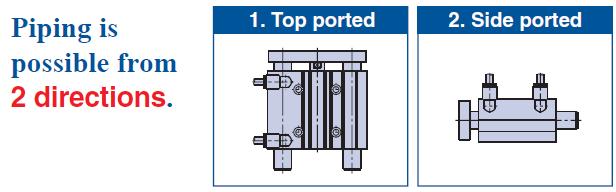
15 11-2. Cushion (With air cushion) 1. Do not open the cushion valve excessively. Air leakage will occur if operated after opening by 4 rotations or more. Furthermore, a stopper mechanism is provided for the cushion valve, and it should not be forced open beyond that position. Be aware that the cushion valve may jump up from the cover when the air is supplied. 1. Be sure to use the cylinder after the air cushion has been adjusted appropriately. First, fully close the cushion valve. Start the operation at the cylinder speed to be used with the load applied, and then open the cushion valve gradually to make the adjustment. The optimal adjustment is that the piston reaches its stroke end and the collision sound is minimized. If the cushion valve is used without adjusting the air cushion appropriately, this may cause damage to the retaining ring or piston. Bore size (mm) Applicable tool 16,20,25,32,40 JIS B4648 hexagon wrench key ,63,80,100 JIS B4648 hexagon wrench key 3 2. Be sure to operate a cylinder equipped with air cushion to the end of the stroke. If it is not operated to the end of the stroke, the effect of the air cushion will not be fully exhibited. Consequently, in cases where the stroke is regulated by an external stopper etc., caution must be exercised, as the air cushion may become completely ineffective. 12. Piping This cylinder can do it by changing the position of the plug as the bottom figure from 2 directions of the top pipe and the side pipe Attention in piping Top piping Side piping 1) Use clean air. If compressed air includes chemicals, synthetic oils containing organic solvents, salt or corrosive gases, etc., it can cause damage or malfunction. 1) Depending on the operating conditions, piping port positions can be changed using a plug. 1M5 After tightening by hand, tighten additional 1/6 to 1/4 rotation with a tightening tool 2Tapered thread for Rc port (MGP) and NPT port (MGP TN) Use the correct tightening torques listed below. 14
, use the stipulated figures as a guide and confirm the air leakage before operation.")
16 Before tightening the plug, wrap pipe tape around it. Also, with regard to the sunk dimension of a plug (dimension a in the drawing), use the stipulated figures as a guide and confirm the air leakage before operation. *If tightening plugs on the top mounting port with more than the proper tightening torque, plugs will be screwed much deeply and air passage will be squeezed. Consequently, the cylinder speed will be restricted. 3Parallel pipe thread for G port (MGP TF) Screw in the plug to the surface of the body (dimension a in the drawing) by checking visually instead of using the tightening torque shown in the table. 2) Secure dry air. If moisture enters cylinder, grease inside the cylinder is washed away and air leak and malfunction may occur due to deterioration of lubrication. Install air cleaning equipment such as air dryer and drain catch to secure dry air. Refer to the catalogue, SMC Air Cleaning Equipment. 3) Supply air filtered and regulated down to the specific pressure. 4) Lubrication isn t necessary because it is a lubrication-less type. The cylinder is lubricated at the factory and can be used without any further lubrication. However, in the event that it will be lubricated, use class 1 turbine oil (with no additives) ISO VG32. Stopping lubrication later may lead to malfunction due to the loss of the original lubricant. Therefore, lubrication must be continued once it has been started. 5) Shorten piping. Since too long cylinder piping makes volume inside the cylinder volume inside the tubing, mist from adiabatic expansion is not exhausted to the air and remains in tubing. It accumulates due to repeated operation and then from water drops. As grease inside the cylinder is washed away, lubrication deteriorates and air leak and malfunction may occur. Take the following measures to prevent them. 1Make tubing between solenoid valve and cylinder as short as possible so that generated mist is surely exhausted into atmosphere. Standard length is: Conversion value for volume inside the cylinder under atmospheric pressure 0.7 Volume inside the tubing 2Send exhaust pressure directly into atmosphere by attaching speed controller or quick exhaust valve to cylinder. 3Set piping port downwards so that moisture inside the piping does not go back to cylinder easily. 15
17 12-3.About the flushing 1) Get rid of trash in the pipe. Do flushing or washing fully before the piping, and get rid of cutting chips in side the pipe, cutting oil, trash, and soon because cutting chips left in the pipe, and cutting oil cause air leak and malfunction when they get into the inside of the cylinder. 1)Prevent tape material from getting in to the pipe. Prevent cutting chips of the pipe screw and tape material from getting in to the pipe inside when you thrust a pipe and fittings, etc., because tape material causes air leak and malfunction when you get into it in the cylinder from the thing in the pipe when you lay a pipe. Also, when pipe tape is used, leave 1.5 to 2 thread ridges exposed at the end of the pipe. 13. Operating Environment 1) Do not use in environments where there is a danger of corrosion. Refer to the construction drawings regarding cylinder materials. 2) In dirty areas, such as dusty locations or where water, oil, etc. splash on the equipment, take suitable measures to protect the entire actuator. Use water resistant cylinders in areas where liquids are scattered. 1) Use the cylinder within specified temperature range. This compact cylinder is applicable within the range from 10 to 60 C. Make sure to keep it during operation. In case of immoderate use over the range, extreme wearing due to hardening of packing may result in air leak and lubrication failure as lubrication grease cannot perform fully. 14. Speed Control 1) When speed controller is used for speed adjustment, throttle air supplied to cylinder or exhausted from cylinder. With the former, cylinder operation may become unstable. Normally, double acting cylinder is adjusted in the latter way. 16
18 15. Troubleshooting Nonconformit y No smooth operation Causes Countermeasures Remarks Lower operating speed than the limit High load factor Meter-in speed controller Consider providing low speed specification. Increase Pressure. Use larger cylinder. Change it to meter-out. High ambient temperature Low ambient temperature Soiled cylinder Water from exhaust air of valve Use heat resistant cylinder. (Type M only) Use cold resistant cylinder. (Available as a special.) Put a cover over cylinder. Shorten piping. Air leak Malfunction Parts breakage Parts deformation Vibration Splashes of water/coolant Excessive eccentric load Excessive lateral load Dust Impact force from high speed operation Excessive eccentric load Excessive lateral load Review where to install the cylinder so as not to receive external force. Put a cover over cylinder. Use cylinder improved in water resistant. Check vertical mounting of model selection with catalogue. Check horizontal mounting of model selection with catalogue. Set a cover over cylinder. Use cylinder with scraper. Check allowable kinetic energy. Adjust cushion (with air cushion) Lower speed. Reduce load Check vertical mounting of model selection with catalogue. Check horizontal mounting of model selection with catalogue. 17
19 16. How to exchange seals Disassemble and assemble the cylinder in clean condition. Wipe it with clean waste How to disassemble Tools : Snap ring plier for hole, Spanner, Socket wrench (or Air impact wrench) 1) Fix the spanner flat of piston rod with a spanner. Loosen the plate set bolt with the socket wrench to remove the guide rod assembly. Or, loosen the plate set bolt with air impact wrench to remove the slide assembly. 2) Remove snap ring with snap ring plier to pull out the collar, the piston rod Assembly. Table.1 Bore size (mm) Snap ring size 16-2.How to remove seals 1) Rod seal Tools:Precision screw driver etc. Insert the fine driver to the collar front to pull out the seal like Fig Plate set bolt tightening torque (N m) 12 RTW RTW RTW RTW RTW RTW RTW RTW RTW RTW Fig. 1 How to remove rod seal 18
20 2) Piston seal First, wipe off the grease around the piston seal. This helps remove of this seal. As piston seal groove is deep, push the seal holding both sides like Fig.2, and pull out the seal risen from the piston surface. 3) Gasket Use precision screw driver etc. Fig. 2 How to remove piston seal 4) Cushion seal (With air cushion) See Fig. 3. Pull out the cushion seal inserting the precision screw driver from the back of the seal and the head cover. Attention should be taken not to hurt the seal groove. Fig. 3 How to remove cushion seal 16-3.How to apply grease Use the grease pack:gr-s or lithium soap radical grease JIS2 corresponding. 1) Rod seal Apply grease slightly to outer circumference of new seal for replace. This helps the seal to accustom to the collar. For the grove, fill it with grease. This is necessary for operation. Groove grease Fig. 4 2) Piston seal Apply grease to outer/inner circumference of seal slightly and evenly to make mounting this to the piston easier. 3) Gasket Apply grease slightly. Provide better sealing and stop falling. 19
21 16-4.How to assemble 1) Mount seals 1 Rod seal Mind the seal direction. Apply grease all over the seal and inner surface of the bush as Fig.5. You may use a precision screw driver to apply grease when small bore diameter. Grease Fig. 5 Rod seal 2Piston seal Apply grease rubbing to seal groove and outer circumference. Grease Fig. 6 Piston seal 3Gasket Mount to the collar groove and the body groove. 4Gasket (With air cushion) Mount to the groove of the collar and the head cover. Mount the gasket of 32 or more to the groove of the head cover and groove inside of the body. The gasket size on the body is larger. Do not mount the gasket to the air passage (groove having through hole) as in Fig. 7. Gasket Grease Rod seal Collar Cushion seal Gasket Rip parts Rip parts Rod side Head side Fig. 7 Gasket position (collar) 20
22 5Cushion seal (With air cushion) Mind the packing direction. Apply grease to inner circumference of the seal has some play, it is normal. Gasket Cushion seal Head cover Gasket Rip parts Rod side Head side Fig. 8 Cushion seal position (Head cover) 2) Assemble cylinder Mount parts with reversed order of disassembling. Assemble order: Piston rod assembly Collar Snap ring Head cover Snap ring Guide rod assembly Apply locking glue to the plate set bolt when mounting the guide rod assembly. And tighten the bolt with tightening torque in table 1. Ensure if the cylinder move smoothly with a hand. Check the air leakage. 21

23 17. Construction Basic type MGPM12 to 25 MGPM32 to
24 MGPL12 to 25 MGPL32 to 100 MGPA12 to 25 MGPA32 to

25 17-2. Air cushion type MGPM 24
26 MGPL MGPA 18. Auto Switch 18-1.Applicable auto switches 25

27 26
 and Its mounting")
28 18-2. Auto switch proper mounting position (detection at stroke end) and Its mounting height 27


29 18-3. Minimum mountable stroke for a cylinder with auto switch(es) Auto switch operating range Part number of auto switch mounting bracket 28
30 Revision history Initial release : 2012/5/21 Revision 1 : 2014/1/30 Add the air cushion , Sotokanda, Chiyoda-ku, Tokyo JAPAN Tel: Fax: URL Note: Specifications are subject to change without prior notice and any obligation on the part of the manufacturer SMC Corporation All Rights Reserved 29
Low Torque Metal Seal Type Rotary Joint. MQR Series
 Doc. No MQR****-OML0002-A. PRODUCT NAME Low Torque Metal Seal Type Rotary Joint MODEL / Series / Product Number MQR Series Contents 1. Contents P1 2. Model / Specifications P2~5 3. Safety Instructions
Doc. no.ck1*-om0066p. PRODUCT NAME Clamp Cylinder. MODEL / Series / Product Number
 Doc. no.ck1*-om0066p PRODUCT NAME Clamp Cylinder MODEL / Series / Product Number CK1*40&63-**Z CKG1*40&63-**Z-** CKP1*40&63-**Z-** Contents Safety Instructions P2 1. Specifications P4 1-1. Specifications
Pressure Relief 3 Port Valve With Locking Holes
 Doc. No. VH*-OMQ0023-B PRODUCT NAME Pressure Relief 3 Port Valve With Locking Holes MODEL / Series / Product Number VHS20-(F,N)01~02A,B(-B,S)(-K,R,Z) VHS30-(F,N)02~03A,B(-B,S)(-K,R,Z) VHS40-(F,N)02~04A,B(-B,S)(-K,R,Z)
No.EX -OME0016-A PRODUCT NAME. SI unit. MODEL / Series / Product Number EX140-SDN1
 No.EX -OME0016-A PRODUCT NAME SI unit MODEL / Series / Product Number EX140-SDN1 Table of Contents 1. Safety instructions 2 2. Specifications 7 2-1. General specifications 7 2-2. Electrical ant network
Doc. no.cm2*-om0064p. PRODUCT NAME Air cylinder. MODEL / Series / Product Number
 Doc. no.cm2*-om0064p PRODUCT NAME Air cylinder MODEL / Series / Product Number C*M2**-*Z C*M2**-*Z-XC85 C*M2**-*Z-X446 Contents Safety Instructions P2 1. Specifications P4 1-1. Specifications 2. Installation
Doc. no.mx*-omp0038-d PRODUCT NAME AIR SLIDE TABLE. MODEL / Series / Product Number
 Doc. no.mx*-omp0038-d PRODUCT NAME AIR SLIDE TABLE MODEL / Series / Product Number MXQ6(A,B)-**Z* MXQ8(A,B,C)-**Z* MXQ12(A,B,C)-**Z* MXQ16(A,B)-**Z* MXQ20(A,B)-**Z* MXQ25(A)-**Z* Contents 1. Pr oduc t
High Vacuum Solenoid Valve PRODUCT NAME. XSA Series MODEL/ Series
 Doc. No. High Vacuum Solenoid Valve PRODUCT NAME XSA Series MODEL/ Series Thank you for purchasing this SMC product. Be sure to read this Operation Manual carefully and understand its contents before operating
Doc. no.vn -OMA0002-D. Process valve PRODUCT NAME. VNA Series MODEL / Series / Product Number
 Doc. no. Process valve PRODUCT NAME VNA Series MODEL / Series / Product Number Contents Safety Instructions ---------------------------------------------------------------------------------- 2,3 Design
This filter enables direct exhaust of air in a clean room! (Cleanliness class 4*: ISO ) (* Based on SMC s measuring conditions.
 (* Based on SMC s measuring conditions.") Clean Exhaust Filter This filter enables direct exhaust of air in a clean room! (Cleanliness class 4*: ISO14644-1) (* Based on SMC s measuring conditions.) Air can be directly exhausted in a clean room
Clean Exhaust Filter This filter enables direct exhaust of air in a clean room! (Cleanliness class 4*: ISO14644-1) (* Based on SMC s measuring conditions.) Air can be directly exhausted in a clean room
AS Series. 4.0 g. Weight: Approx. 27% lighter. Flow Rate Reproducibility. Larger Knob. Easy Identification of Product Type. 5.5 g.
 Speed Controller with One-touch Fittings In-line In-line Type y Easo t use RoHS Brass Stainless steel Reduces flow setting time! Push-lock type Knob O.D.: Almost doubled! Easy to lock ø9.4 Unlock ø5 Lock
69% 30.5 mm 16 mm. Compact Guide Cylinder. Compact. lighter 0.32 kga0.1 kg (Compared with the current MGP-Z series, ø16, 10 mm stroke) Weight
 Weight") Compact Guide Cylinder ø12, ø16, ø20, ø25, ø32, ø40, ø50, ø63, ø80, ø100 RoHS Compact Overall length shortened New s ø80, ø100 added. Port thread types NPT, G added. Height shortened JMGP ø32 25 mm stroke
Compact Guide Cylinder ø12, ø16, ø20, ø25, ø32, ø40, ø50, ø63, ø80, ø100 RoHS Compact Overall length shortened New s ø80, ø100 added. Port thread types NPT, G added. Height shortened JMGP ø32 25 mm stroke
HEAVY DUTY STOPPER CYLINDER
 Doc. no. RS2H-OM0012P- B PRODUCT NAME HEAVY DUTY STOPPER CYLINDER MODEL / Series / Product Number RS2H Series (φ50 to φ80) Contents Safety Instructions P.2 1. Specifications P.4 1-1. Cylinder specifications
49.5 mm Overall. 30 mm MXZ ø20. Compact. Compact Cylinder with Linear Guide. MXZ Series CAT.ES20-236A. ø12, ø16, ø20, ø25. MXZ ø20, 10 mm stroke.
 Compact Cylinder with Linear Guide ø12, ø16, ø20, ø25 RoHS Compact 49.5 mm Overall length MXZ ø20, 10 mm stroke 30 mm MXZ ø20 Width Design and assembly time is reduced due to integration of a linear guide
Doc. no.vn-omm0001-c. Coolant valve PRODUCT NAME. VNC/VNH Series MODEL / Series / Product Number
 Doc. no. Coolant valve PRODUCT NAME VNC/VNH Series MODEL / Series / Product Number Contents Safety Instructions ---------------------------------------------------------------------------------- 2,3 Precautions
High Vacuum Solenoid Valve PRODUCT NAME. XSA Series MODEL/ Series
 Doc. No. High Vacuum Solenoid Valve PRODUCT NAME XSA Series MODEL/ Series Thank you for purchasing this SMC product. Be sure to read this Operation Manual carefully and understand its contents before operating
1.8 w Port Solenoid Valve Direct Operated Poppet Type. New. Series VT307 CAT.ES11-107A. Power consumption
 Port Solenoid Valve Direct Operated Poppet Type Power consumption Vacuum applications New [Option] RoHS 4 Standard wtype (Existing product: 4.8 W) 0. kpa Energy-saving type.8 w (Existing product: W) A
Lock unit MWB*32&100-UT-* MWB*32&100TN-UT-* MWB*32&100TF-UT-*
 Doc. no.mwb*-om0078q PRODUCT NAME Lock unit MODEL / Series / Product Number MWB*32&100-UT-* MWB*32&100TN-UT-* MWB*32&100TF-UT-* Contents Safety Instructions P. 3 1. Product Specifications P. 5 1-1. Lock
Solid State Auto Switch D-M9#A#
 PRODUCT NAME Solid State Auto Switch MODEL / Series / Product Number D-M9#A# Contents Safety Instructions 2 Model Indication and How to Order 8 Summary of Product parts 10 Summary of Product parts 10 Definition
Magnetic Field Resistant 2-color Indication Type Solid State Auto Switch
 PRODUCT NAME Magnetic Field Resistant 2-color Indication Type Solid State Auto Switch MODEL / Series / Product Number D-P3DW(A) * Series Contents Safety Instructions 2 Model Indication Method 8 Names and
Coolant valve. SGC/SGH Series
 Doc. no. PRODUCT NAME Coolant valve MODEL / Series / Product Number SGC/SGH Series Contents Safety Instructions ------------------------------------------------------------------------------------- 2,3
Doc. No.VT307 -OMH0001-C. 3 Port Direct Operated Solenoid Valve PRODUCT NAME. VT307 Series MODEL/ Series
 Doc. No. 3 Port Direct Operated Solenoid Valve PRODUCT NAME VT307 Series MODEL/ Series Contents Safety Instructions ------------------------------------------------------------------------------- 2,3 Precautions
Speed Controller with Indicator
 Speed Controller with Indicator Numerical indication of handle rotation for flow rate reduces flow setting time and setting errors! Indicator window Body size Body size or larger Indicator window Number
High Vacuum L Type Valve
 Doc. no. PRODUCT NAME High Vacuum L Type Valve MODEL / Series / Product Number XLFV-2 Series Contents Safety Instructions - - - - - - - - - - - - - - - - - - - - - - - - - - - - 2 1. Product Specific Precautions
RJ M8 size absorption time. Energy (J) RJ-L type. With cap. Short stroke type
 RJ-L type. With cap. Short stroke type") Shock Absorber Soft type Stops transported objects softly % reduced absorption time Unique mechanism to achieve a variable sectional area of the fluid channel proportional to the stroke (compared with
Shock Absorber Soft type Stops transported objects softly % reduced absorption time Unique mechanism to achieve a variable sectional area of the fluid channel proportional to the stroke (compared with
Doc. No.VQ1000V-OMM0002-B. Solenoid Valve PRODUCT NAME. VQ1000/2000 Series (PILOT VALVE : V100) MODEL/ Series
 MODEL/ Series") Doc. Solenoid Valve PRODUCT NAME VQ1000/2000 Series (PILOT VALVE : V100) MODEL/ Series Contents Safety Instructions ---------------------------------------------------------------------------- 2,3 Precautions
Doc. Solenoid Valve PRODUCT NAME VQ1000/2000 Series (PILOT VALVE : V100) MODEL/ Series Contents Safety Instructions ---------------------------------------------------------------------------- 2,3 Precautions
Rotary Actuators Precautions 1 Be sure to read this before handling.
 Precautions 1 1. Confirm the specifications. Products represented in this catalog are designed only for use in compressed air systems (including vacuum). Do not operate at pressures or temperatures, etc.,
0.1 mm. Actuator Position Sensor. D-MP Series. Actuator stroke position is output with an analog signal. Repeatability IP67.
 Actuator Position Sensor Actuator stroke position is output with an analog signal. IP67 Repeatability 0.1 mm (Varies depending on the operating conditions.) Analog output 4 measurement ment ranges Voltage
ø20, ø32 ø50, ø63, ø80 How to Order Piping direction Flange side Nil Cylinder stroke 15mm 15 (RSH20) 20mm 20 (RSH32) 30 D L Cylinder stroke
 20mm 20 (RSH32) 30 D L Cylinder stroke") Heavy Duty Stopper Cylinder Series RSH/RS1H ø, ø32 ø, ø63, ø How to Order Piping direction Flange side Nil Positional relationship of lever and port RSH Port Direction of transfer 32mm Bore size only 32
Heavy Duty Stopper Cylinder Series RSH/RS1H ø, ø32 ø, ø63, ø How to Order Piping direction Flange side Nil Positional relationship of lever and port RSH Port Direction of transfer 32mm Bore size only 32
Doc. No.VG300 -OMH0002-B. 3 Port Solenoid Valve PRODUCT NAME. VG342 Series MODEL/ Series
 Doc. No. 3 Port Solenoid Valve PRODUCT NAME VG342 Series MODEL/ Series Contents Safety Instructions ---------------------------------------------------------------------------- 2,3 Precautions on Design
Doc. No.VQ4000V-OMV0001. Solenoid Valve PRODUCT NAME. VQ4000/5000 (Pilot Valve V100) MODEL/ Series
 MODEL/ Series") Doc. No. Solenoid Valve PRODUCT NAME VQ4000/5000 (Pilot Valve V100) MODEL/ Series Contents Safety Instructions ---------------------------------------------------------------------------- 2,3 Precautions
Doc. No. Solenoid Valve PRODUCT NAME VQ4000/5000 (Pilot Valve V100) MODEL/ Series Contents Safety Instructions ---------------------------------------------------------------------------- 2,3 Precautions
Digital Flow Switch (Remote type sensor unit)
") PRODUCT NAME Digital Flow Switch (Remote type sensor unit) MODEL / Series / Product Number PFM5## Table of Contents Safety Instructions 2 Model Indication and How to Order 10 Summary of Product parts 13
PRODUCT NAME Digital Flow Switch (Remote type sensor unit) MODEL / Series / Product Number PFM5## Table of Contents Safety Instructions 2 Model Indication and How to Order 10 Summary of Product parts 13
Regulator Valve. VEX1 Series
 Doc. no. PRODUCT NAME Regulator Valve MODEL / Series / Product Number VEX1 Series Contents Safety Instructions ---------------------------------------------------------------------------------- 2,3 Precautions
ROD SLIDERS INDEX ACTUATORS GENERAL CATALOG. Characteristics 779. Handling Instructions, and Precautions 783
 Presenting our CAD drawing data catalog ACTUATORS GENERAL CATALOG ROD SLIDERS INDEX Characteristics 779 Handling Instructions, and Precautions 783 Standard Cylinders Specifications 785 Order 78 Dimensions
Direct Operated 3-port solenoid valve
 Doc. No. PRODUCT NAME Direct Operated 3-port solenoid valve MODEL/ Series Series: VT315 Contents Safety Instructions --------------------------------------------------------------------------- 2,3 Precautions
Digital Gap Checker. ISA3 series
 PRODUCT NAME Digital Gap Checker MODEL / Series / Product Number ISA3 series Table of Contents 1 Before Use Safety Instructions 2 2 About this product Features 7 Model Indication and How to Order 8 Summary
45% 6.5 mm. 6 mm. 4 mm. Compact Cylinder. Compact. lighter. JCQ Series CAT.ES20-239C. Weight. ø12, ø16, ø20, ø25, ø32, ø40, ø50, ø63, ø80, ø100
 Compact Cylinder ø12, ø16, ø20, ø25, ø32, ø40, ø50, ø63, ø80, ø100 RoHS Compact Both ends tapped mounting added. New s ø80, ø100 added. Port thread types NPT, G added. Overall length shortened 10 mm stroke
Pressure Sensor for General Fluids PSE570/573/574
 PRODUCT NAME Pressure Sensor for General Fluids MODEL / Series / Product Number PSE570/573/574 Table of Contents Safety Instructions 2 Model Identification and How to Order 8 Names of Parts of Product
Two Hand Control Valve
 Two Hand Control Valve Series n output is available through synchronized, twohanded operation (within 0.5 s)! Conforming to EN574 RoHS (Interchangeable with XT92-67 ) Example of a basic circuit diagram
Digital Gap Checker. ISA3 series
 PRODUCT NAME Digital Gap Checker MODEL / Series / Product Number ISA3 series Table of Contents 1 Before Use Safety Instructions 2 2 About this product Features 7 Model Indication and How to Order 8 Summary
SI unit for AS-Interface EX250-SAS#
 PRODUCT NAME SI unitfor AS-Interface MODEL / Series / Product Number EX250-SAS# Table of Contents Safety Instructions 2 Product Outline 8 Model Indication and How to Order 9 Summary of Product elements
MULTI SLIDERS CONTENTS
 CAD drawing data catalog is available. ACTUATORS GENERAL CATALOG CONTENTS Features 923 Handling Instructions and Precautions 925 Specifications 929 Order Codes 930 Inner Construction 931 Dimensions 932
Solid State Auto Switch
 PRODUCT NAME Solid State Auto Switch MODEL / Series / Product Number D-M9## D-M9#W# Contents Safety Instructions 2 Model Indication and How to Order 9 Summary of Product parts 10 Definition and terminology
SLIDE TABLES CONTENTS
 CAD drawing data catalog is available. ACTUATORS GENERAL CATALOG SLIDE TALES CONTENTS Features 979 Safety Precautions, Handling Instructions and Precautions 981 Specifications 985 Order Codes 986 Inner
Free position locking flat and compact cylinder UFCD Series
 Space-saving cylinder ensures safety during work in power failures or accidents. Free position locking flat and compact cylinder UFCD Series Free position locking flat and compact cylinder UFCD Series
Electro-pneumatic proportional valve
 Doc. no. PRODUCT NAME Electro-pneumatic proportional valve MODEL / Series / Product Number VEP/VEF/VEA/VER Series Contents Safety Instructions ----------------------------------------------------------------------------------
Operation Manual. Model name. MRHQ Rotary Gripper. Part number / Series MRHQ10,16,20,25
 Doc. no. MRHQ-OM00002-C Operation Manual Model name MRHQ Rotary Gripper Part number / Series MRHQ10,16,20,25 - Install and operate the product only after reading the Operation Manual carefully and understanding
Wide Type Parallel Style Air Gripper
 Wide Type Parallel Style ir Gripper ø, ø6, ø2, ø25 Weight Max. % reduction 585 g 525 g ø6, Opening/Closing stroke: 3 mm RoHS Weight reduced by the change of the body shape and internal construction M Dust
3 Port 3 Position Valve
 Port Position Valve Pilot Solenoid ir Operated ohs Intermediate stopping of cylinders * up to ø15 is possible. Pilot solenoid Manifold ir operated * For VEX 4, 00 mm/s, horizontal movement Power consumption:
Digital Flow Switch (Remote type monitor unit)
") PRODUCT NAME Digital Flow Switch (Remote type monitor unit) MODEL / Series / Product Number PF2A3## PF2W3## PF2D3## Table of Contents Safety Instructions 2 Model Indication and How to Order 9 Summary of
PRODUCT NAME Digital Flow Switch (Remote type monitor unit) MODEL / Series / Product Number PF2A3## PF2W3## PF2D3## Table of Contents Safety Instructions 2 Model Indication and How to Order 9 Summary of
Disassembly / Reassembly Procedure
 08-T059 Disassembly / Reassembly Procedure HEAVY DUTY TYPE PNEUMATIC CYLINDER 10A-3 SERIES Failure to observe the instructions given in this manual could cause this equipment
58.5 mm. 54% lighter. Air Cylinder ø20, ø25, ø32, ø40. Approx. 1/3 97 mm. 63% reduction. 38% reduction. JCM Series CAT.ES20-237C.
 Air Cylinder ø20, ø25, ø32, ø40 RoS Overall length shortened Approx. 1/3 97 mm 50 mm stroke JCM ø40 Female thread 63% reduction 50 mm stroke 58.5 mm JCM ø40 Male thread 38% reduction 50 mm stroke New Shortened
22mm Space required between the bottom of the cylinder body and your equipment is reduced.
 Compact Guide Cylinder ø2,,, ø2,,, ø0, ø63,, ø0 With air cushion Water resistant cylinder are now available. New Up to 7% Weight reduced! New Weight reduced by up to 7% with a shorter guide rod and thinner
Exhaust Throttle (Needle) Valve ET
 Valve ET") http://www.pisco.co.jp CONTROLLER VALVE TUBE MAKE-TO-ORDER PRODUCTS Exhaust Throttle (Needle) Valve Exhaust Throttle (Needle) Valve ET 494 Exhaust Throttle (Needle) Valve with Silencer. Directly Connectable
http://www.pisco.co.jp CONTROLLER VALVE TUBE MAKE-TO-ORDER PRODUCTS Exhaust Throttle (Needle) Valve Exhaust Throttle (Needle) Valve ET 494 Exhaust Throttle (Needle) Valve with Silencer. Directly Connectable
Compact Guide Cylinder Series MGQ
 Compact Guide Cylinder Series ø, ø, ø, ø, ø, ø, ø, ø, ø, ø0 ir cylinder with guide integrated that has achieved anti-lateral load and high non-rotating accuracy. Space-saving cylinder. Suitable as stoppers
Compact Guide Cylinder Series MGP
 Compact Guide Cylinder Series MGP ø2, ø, ø, ø, ø, ø, ø, ø,, ø0 MGJ MGP MGQ MGG MGC MGF MGZ MGT Series Variations Series Bearing type Cushion 2 0 Page Standard type MGP With air cushion MGP With end lock
Precision Cylinder. MTS Series. ø8, ø12, ø16, ø20, ø25, ø32, ø40 MXH MXS MXQ MXQ MXF MXW MXJ MXP MXY MTS D- -X. Series Variations MTS8
 Precision Cylinder Series, ø, ø6, ø, ø, ø, ø MXS Series Variations Model 8 Standard stroke (mm) 7 7 Rod end configuration Cushion Rubber bumper End lock Made to Order Rod Variable stroke/ through-hole
High Vacuum Solenoid Valve. 25% reduction. Max. Weight. 18% * lighter. Max. * XSA2-2 AC 100 V, 200 V, 110 V, 220 V, 240 V, 48 V, 24 V, 230 V DC
 Normal lose High Vacuum Solenoid Valve Minimum operating pressure * 1x10 6 Pa(abs) * OUT side Leakage Internal 1.3 x10 9 Pa m3/s Note) Note) Except grommet/ RoHS External 1.3 x10 11 Pa m3/s 2 types of
Digital Flow Switch (Integrated display type)
") PRODUCT NAME Digital Flow Switch (Integrated display type) MODEL / Series / Product Number PF2A7## Table of Contents Safety Instructions 2 Model Indication and How to Order 10 Summary of Product parts
PRODUCT NAME Digital Flow Switch (Integrated display type) MODEL / Series / Product Number PF2A7## Table of Contents Safety Instructions 2 Model Indication and How to Order 10 Summary of Product parts
Multi-Circuit Rotary Block
 http://www.pisco.co.jp FITTING CONTROLLER VALVE TUBE MAKE-TO-ORDER PRODUCTS Multi-Circuit Block for Rotating Applications Multi-Circuit Rotary Block 302 Make to Order Suitable for Low-Speed Rotating Applications
How to Order. Nozzle. Nil Connection size N02 N03 F02 F H06 H08 H10 H07 H09 H11
 Blow Gun RoHS How to Order VMG W Blow gun Standard type Series Resin body lever type W BU Piping entry Bottom Top Body color White ark blue Symbol Nil 3 4 3 3 4 3 3 33 34 Male High efficiency Low noise
Series AV2000/3000/4000/5000
 Soft Start-up Valve Series AV/3/4/5 Series introduced! A start-up valve that gradually increases supply pressure during start up and rapidly exhausts system air when the supply air is shut off AC AV AU
Air Catch Sensor ISA2
 No.PS##-OMF0007-C PRODUCT NAME Air Catch Sensor MODEL / Series / Product Number ISA2 Table of Contents Safety Instructions 2 Model Indication and How to Order 11 Summary of Product parts 13 Definition
10 million cycles. Improved durability. Shock Absorber/Soft type. RJ Series. Maximum operating cycles M6, M8, M10, M14, M20, M27
 Shock Absorber/Soft type Series M, M, M, M, M, M Improved durability RoS Long-term continuous operation has been realized by employing the pre-load mechanism, newly-developed oil seals. Maximum operating
Soft Start-up Valve. AV2000/3000/4000/5000 Series
 Soft Start-up Valve V000/000/000/000 Series [Option] C- R- W- C R - W - Start-up valve for low speed air supply to gradually raise initial pressure in an air system and for quick exhaust by cutting off
22mm. Compact Guide Cylinder (Basic type) New. Up to. Series MGP. Weight reduced!
 New. Up to. Series MGP. Weight reduced!") 1-161 Compact Guide Cylinder (Basic type) ø12, ø16, ø20, ø25, ø32, ø40, ø50, ø63, ø80, ø100 Up to 17% Weight reduced! New Weight reduced by up to 17% with a shorter guide rod and thinner plate Guide rod
1-161 Compact Guide Cylinder (Basic type) ø12, ø16, ø20, ø25, ø32, ø40, ø50, ø63, ø80, ø100 Up to 17% Weight reduced! New Weight reduced by up to 17% with a shorter guide rod and thinner plate Guide rod
SI unit for Ethernet POWERLINK
 PRODUCT NAME SI unit for Ethernet POWERLINK MODEL / Series / Product Number EX260 Series Table of Contents Safety Instructions 2 Model Indication and How to Order 8 Summary of Product elements 9 Installation
Digital Flow Switch (Integrated display type)
") PRODUCT NAME Digital Flow Switch (Integrated display type) MODEL / Series / Product Number PF2A7##H Table of Contents Safety Instructions 2 Model Indication and How to Order 10 Summary of Product parts
PRODUCT NAME Digital Flow Switch (Integrated display type) MODEL / Series / Product Number PF2A7##H Table of Contents Safety Instructions 2 Model Indication and How to Order 10 Summary of Product parts
Speed Controller with Uni One-touch Fitting Push-lock type. New-stand male threads for piping that reduces the screw-in time by 1/3. Model.
 Speed Controller with Uni One-touch Fitting Push-lock type Series Elbow Universal Brass New-stand male threads for piping that reduces the screw-in time by 1/3. Gasket Female thread Rc, G NP, NPF Shape
SI unit for EtherCAT. EX260 Series
 PRODUCT NAME SI unit for EtherCAT MODEL / Series / Product Number EX260 Series Contents Safety Instructions 2 How to Order 7 Summary of Product elements 8 Installation and Cabling 9 Installation 9 Connecting
Series CYP. Clean rodless cylinder ø15, ø32. How to Order
 Series Clean rodless cylinder ø15, ø32 How to Order ir cylinder Clean rodless cylinder ore size (mm) 15 32 15 Cylinder bore size 15 15mm 32 32mm TN TF Port type M5 x 0.8 15 c NPT Standard stroke Standard
Speed Controller High Flow
 http://www.pisco.co.jp CONTROLLER VALVE TUBE MAKE-TO-ORDER PRODUCTS Speed Control Valve for High Speed Cylinder High Flow Speed Control Valve for Actuator. High Flow Type with Same Size as. Suitable for
Compact Slide. Series MXH ø6, ø10, ø16, ø20
 Compact Slide Series ø, ø, ø, ø The use of an endless track linear guide produces a table cylinder having excellent rigidity, linearity and non-rotating accuracy. Endless track linear guide Series Variations
Compact Guide Cylinder
 Compact Guide Cylinder Series ø2, ø, ø, ø2, ø, ø, ø, ø, ø, ø0 Series standard type and series high precision ball bushing bearing type (except with end lock) products have been remodeled for a lightweight
Low Torque Rotary Joint
 Low Torque Rotary Joint Series MQR Metal Seal Type K Long service life billion rotations MQR : billion rotations MQR : 0. billion rotations MQR : 0. billion rotations MQR8 : 0. billion rotations MQR: 0.
Guide Table. ø40, ø63, ø100
 Guide Table Series MGF ø, ø, ø Low-profile compact cylinder utilizes a large concentric guiding sleeve to provide excellent eccentric load resistance. Mounting height greatly reduced Low-profile cylinder
Speed Controller with One-touch Fitting
 Speed Controller with One-touch Fitting Series Elbow Type Reduces labor time! Elbow Brass Stainless steel Electroless nickel plated Stainless steel 33 RoHS TMH y Easo t e us Push-lock type Larger handle
Throttle (Needle) Valve PP Series
 Valve PP Series") http://www.pisco.co.jp CONTROLLER VALVE TUBE MAKE-TO-ORDER PRODUCTS Push-In Fitting Type Flow Control Valve for Clean Environment Throttle (Needle) Valve 466 Copper alloy free material Nongrease Clean-room
http://www.pisco.co.jp CONTROLLER VALVE TUBE MAKE-TO-ORDER PRODUCTS Push-In Fitting Type Flow Control Valve for Clean Environment Throttle (Needle) Valve 466 Copper alloy free material Nongrease Clean-room
Guide Table. MGF Series
 Guide Table MGF Series ø, ø, ø0 Low-profile compact cylinder utilizes a large concentric guiding sleeve to provide excellent eccentric load resistance. Mounting height greatly reduced Low-profile cylinder
MONOSASHI-KUN. CE1* Series
 Doc. no.ce*-omd0004-e PRODUCT NAME MONOSASHI-KUN MODEL / Series / Product Number CE1* Series Contents 1. Safety Instructions 1~6 2. Product Summary 2-1. System Configuration 7 2-2. How to Order 7~8 2-2-1.
Compact Guide Cylinder
 Compact Guide Cylinder Series ø, ø, ø, ø, ø, ø, ø, ø, ø, ø ir cylinder with guide integrated that has achieved anti-lateral load and high non-rotating accuracy. Space-saving cylinder. Suitable as stoppers
Trimmer Auto Switch D-F7K/D-Y7K D-RNK/D-RPK
 PRODUCT NAME Trimmer Auto Switch MODEL / Series / Product Number D-F7K/D-Y7K D-RNK/D-RPK Table of Contents Safety Instructions 2 Model Indication and How to Order 9 Summary of Product parts 10 Definition
EX##-OMN0011-A. SI unit for EtherCAT PRODUCT NAME. EX260 Series MODEL/ Series
 EX##-OMN0011-A SI unit for EtherCAT PRODUCT NAME EX260 Series MODEL/ Series Contents Safety Instructions 2 How to Order 7 Summary of Product elements 8 Installation and Cabling 9 General instructions on
AV2000-A/3000-A/4000-A/5000-A
 Soft Start-up Valve Start-up valve for low speed air supply to gradually raise initial pressure in an air system and for quick exhaust by cutting off air supply Power consumption: 0.35 W * At 12/24 VDC
3/4/5-Port Solenoid Valves Precautions 1 Be sure to read this before handling products.
 Precautions 1 1. Confirm the specifications. Products represented in this catalog are designed only for use in compressed air systems (including vacuum). Do not operate at pressures, temperatures, etc.,
Series CYP. ø15, ø32 Clean Rodless Cylinder. How to Order
 ø15, ø32 Clean odless Cylinder How to Order CYP 15 200 Y59 Clean rodless cylinder Cylinder bore size 15 15 mm 32 32 mm Standard stroke ore size (mm) Standard stroke (mm) 100, 150, 200, 250, 300, 350 15/32
Added 100 mm and 150 mm lengths. Actuators 10% Air leakage 20% Air blow 70% Current model
 Blow Gun Series 20% reduction in power consumption with the SMC Blow gun + S coupler + Coil tube 10% reduction with the Blow gun () only RoHS With cover Extension nozzle Added mm and 150 mm lengths Pressure
CO 3-WAY PNEUMATIC VALVE INSTRUCTION MANUAL 2080
 CO 3-WAY PNEUMATIC VALVE INSTRUCTION MANUAL 2080 STI S.r.l has taken every care in collecting and verifying the documentation contained in this Instruction Manual. The information herein contained are
Miniature Guide Rod Cylinder ±0.1. Mounting from 2 directions
 Miniature Guide Rod Cylinder Series Non-rotating accuracy : Height ±0.1 Mounting from 2 directions idth Overall length Two auto switches can be mounted even for mm strokes Integral wiring/piping to one
(Actual size) 2 switches 10 switches. Push Adjust to the set-value by the or button.
 2 switches 10 switches. Push Adjust to the set-value by the or button.") Digital Pressure Switch RoHS compliant Low profile 9.8 mm (Actual size) 13.5 mm 53.4 mm Vertical mounting space reduced to approx.! 1 2 Reduced in depth! 26.1 mm Can copy to up to 1 switches simultaneously.
Digital Pressure Switch RoHS compliant Low profile 9.8 mm (Actual size) 13.5 mm 53.4 mm Vertical mounting space reduced to approx.! 1 2 Reduced in depth! 26.1 mm Can copy to up to 1 switches simultaneously.
Speed Controller with One-touch Fitting
 Speed Controller with One-touch Fitting S Series Push-lock Type Reduces labor time! Easy to use Easy to lock Unlock Push-lock type Lock Improved tube insertion/removal Max. Insertion force: 30% (8 N) reduction
Digital Pressure Switch
 PRODUCT NAME Digital Pressure Switch MODEL / Series / Product Number ZSE80(F) ISE80(H) Table of Contents Safety Instructions 2 Model Indication and How to order 9 Summary of Product parts 10 Definition
Digital pressure switch for energy-saving control ejector
 PRODUCT NAME Digital pressure switch for energy-saving control ejector MODEL / Series / Product Number ZK2-ZSV####-A Table of Contents Safety Instructions 2 Model indication and How to order 9 Summary
Free Mount Cylinder. Series. Series CU CAT.EUS20-95 B -UK. Space-saving. Auto Switch Capable P. 4, 23, 37 P. 45 P. 43
 CAT.EUS- B -UK Free Mount Cylinder A space-saving air cylinder with multiple surfaces capable of direct mounting. Offered in many variations. Space-saving The multiple surface direct mounted rectangular
Low Torque Rotary Joint
 Low Torque Rotary Joint MQR Series Metal Seal Type Long service life billion rotations MQR : billion rotations MQR : 0. billion rotations MQR : 0. billion rotations MQR8 : 0. billion rotations MQR: 0.
ACTUATORS GENERAL CATALOG
 CAD drawing data catalog is available. ACTUATORS GENERAL CATALOG ROTARY ACTUATORS VANE TYPE SERIES CONTENTS RAN (Standard Type) Basic Model and Configuration 259 Specifications 26 Order Codes 264 Dimensions
1988 Chevrolet Pickup V SUSPENSION - FRONT (4WD)' 'Front Suspension - "V" Series 1988 SUSPENSION - FRONT (4WD) Front Suspension - "V" Series
' 'Front Suspension - V Series 1988 SUSPENSION - FRONT (4WD) Front Suspension - V Series") 1988 SUSPENSION - FRONT (4WD) Front Suspension - "V" Series DESCRIPTION NOTE: Vehicle serial numbers used in this article has been abbreviated for common reference to Chevrolet and GMC models. Chevrolet
1988 SUSPENSION - FRONT (4WD) Front Suspension - "V" Series DESCRIPTION NOTE: Vehicle serial numbers used in this article has been abbreviated for common reference to Chevrolet and GMC models. Chevrolet
POWER STEERING TO INDEX POWER STEERING SYSTEM PRECAUTIONS... OPERATION CHECK... PROBLEM SYMPTOMS TABLE... VANE PUMP ASSEMBLY COMPONENTS...
 TO INDEX STEERING POWER STEERING POWER STEERING SYSTEM PRECAUTIONS.............................................. OPERATION CHECK......................................... PROBLEM SYMPTOMS TABLE.................................
Push-In Fitting Type Quick Exhaust Valve
 http://www.pisco.co.jp CONTROLLER VALVE TUBE MAKE-TO-ORDER PRODUCTS Push-In Fitting Type Valve Valve 482 Suitable for High-Speed Cylinder. Standard Valve is equipped with Silencer. Re-adjustment of exhaust
240% 19% reduced. Compact Slide. MXH Series. Improved by up to. With new high rigidity linear guide. 369g. ø6, ø10, ø16, ø g.
 Compact Slide Series ø, ø, ø, ø RoHS Allowable moment MXS Improved by up to MXQ MXQ 2% MXF MXW MXJ MXP MXY With new high rigidity linear guide MTS Allowable moment improvement illustrated below Allowable
Free Mount Cylinder. Series CU. A space-saving air cylinder with multiple surfaces capable of mounting directly. Offered in rich variations.
 Free Mount Cylinder Series CU A space-saving air cylinder with multiple surfaces capable of mounting directly. Offered in rich variations. Space-saving The multiple surface direct mounting with a square