Contents. Directional Control Valve 3 Series CV 452. Page 3-4. General Information. Page 5. Technical data. Page 6. Performance Curves.
|
|
|
- Ashlyn Moore
- 6 years ago
- Views:
Transcription
1
2


3 Contents Page 3-4 Page 5 Page 6 Page 7 Page 8 Page 9 Page 10 Page 11 Page 12 Page 13 Page 14 General Information Technical data Performance Curves Dimensions - Basics Valve Dimensions - LS Valve Secondary Valve Spools - Control characteristics Spool Controls Accessories Schematics Order Code Directional Control Valve 3
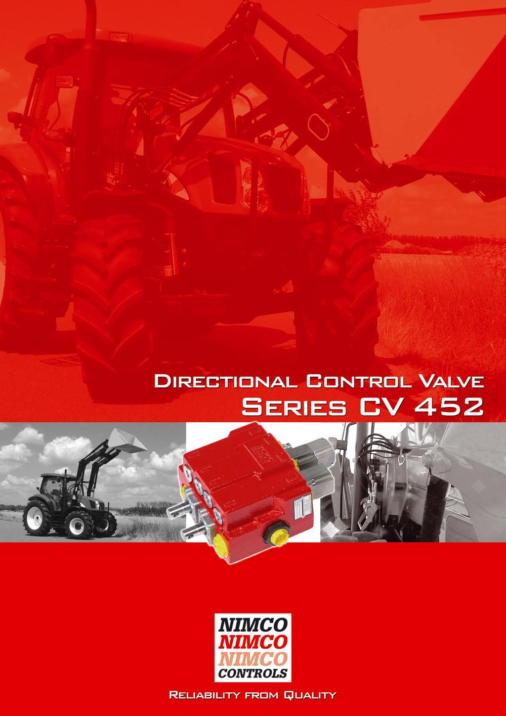
4 General Information The CV452 is a modular 2-spool monoblock valve. Produced in three model designs, open center, constant pressure and load-sensing. The open center and constant pressure designs can be serial connected to achieve additional spool functions by using a high pressure carry-over fitting. The valve is designed for a maximum working pressure of 320 bar (4600 psi) with a recommended flow from 15 to 110 l/min (4-29 USGpm). The CV452 valve offers optimized characteristics with regard to function, capacity and quality. It is designed with the machine builders high demands of cost effectiveness, function and need of exceptionally good load maneuverability in mind. Particularly suitable for use on modern agricultural, or construction, loaders and other equipment where precise load control is required. The uniquely designed valve body casting results in exceptionally low pressure drops leading to improved performance and longer life not only of the control valve but also of the other components in the hydraulic system. The CV452 is manufactured using the highest quality cast iron which in combination with NIMCO s advanced machining and control methods assures the precise accuracy of every component. Each valve is tested and the results documented prior to shipment. The CV452CP Constant Pressure is used in systems where a higher demand for parallel control of the function is desired. The CV452LS Load-sensing can be used with either a variable or a fixed pump. The extraordinary good parallel control of the functions is achieved in both versions. However, the main reason for using LSsystem, energy-saving, is lost when a fixed pump is used. Easy assembly -The NIMCO concept As the cylinder ports are all located in-line with the spools, all plumbing and controls can be done from one side. The valve has two inlet and outlet ports allowing alternative connections that allows for simplified plumbing in less space. It also allows for the use of quick couplers to be assembled directly on to the valve. Minimized spool leakage. Hard chromium plated spools and a specially developed honing method provides absolute minimum spool leakage of the valve. 4 Directional Control Valve
5 General Information Excellent load control. CV452 spools are designed to provide optimum control characteristics over the valves entire flow range. Full utilization of the spool stroke. Optimized metering grooves are integrated in each spool and the precise machining of very component allows the entire stroke of the spool to be used. This allows full control of the load whether the operator is using very little or full flow capacity. In addition the movement of any spool in any direction will give the same speed of machine function, enhancing safety and reliability. Load holding check valves are integrated in each section. Multifunctional control. Both spools can be operated at the same time even when very large differences in load are at hand due to the NIMCO s unique spool and internal valve design. Uniform and low lever forces. By combining the unique design features of the valve body and the spools an excellent balance of the dynamic forces is achieved throughout the entire pressure and flow range. This keeps spring forces at a minimum and makes the valve very easy to operate by hand lever as well as with cables up to 3500 mm (138 inch) length. Wide range of accessories. A wide range of spools and remote controls such as single or joystick cable controls, pneumatic, electrohydraulic proportional, or electrical on/off controls are available. A special Quick-connection system is available for the CV-452, allowing for easy and fast change over of a front end loader from one tractor to another without having to individually connect and disconnect each coupling. Directional Control Valve 5
6 Technical Data Max Pressure Setting Main Relief Valve Port Relief Valve Tank line Flow rates Max for the Valve Temperature Range Fluid Mineral Oil Spool Leakage 100 bar (1450 psi) and 25 mm²/s (cst) (117SSU) viscosity A and B port bar l/min 110 C -40 to +80 cm³/min psi US gpm 29 F -40 to +176 inch³/min Filtration Contamination level equal to or better then Viscosity Recommended operating Viscosity range Start viscosity up to Weight CV452 Operating force on the spool Spring centred Detent in Detent out 18/14 according to ISO 4406 mm²/s kg 12 N NAS 1638-class 10 cst lbs 26,5 kp Directional Control Valve
7 Performance Curves Pressure Drop P T Pressure Drop P A(B) Pressure Drop A(B) T Directional Control Valve 7
8 Dimensions - Basics Valve The dimensions outside the brackets are in mm and the dimensions inside are in inches. SAE 3/4-16 SAE8 3/4-16 SAE8 The dimensions outside the brackets are in mm and the dimensions inside are in inches. Port Size A, A2, B1, B2 P1, P2 T1, T2 BSP 1/2 1/2 3/4 Metric M18 x 1.5 M18 x 1.5 M22 x /16-12 SAE12 8 Directional Control Valve
9 Dimensions - LS Valve Please note that this LS valve is shown with optional cable adapters and High pressure carry-over (Power Beyond) assembled on to the valve for measurement purposes. The dimensions outside the brackets are in mm and the dimensions inside are in inches. Port Size A, A2, B1, B2 P2 T2 S BSP 1/2 1/2 3/4 1/4 Metric M18 x 1.5 M18 x 1.5 M22 x 1.5 M12 x 1.5 SAE 3/4-16 SAE8 3/4-16 SAE8 11/16-12 SAE12 7/16-20 SAE4 Directional Control Valve 9
10 Secondary Valve Main relief valve. Differential operated relief valve for the main circuit. Adjustable from 35 to 320 bar ( psi). Order code: RV+pressure setting Cylinder port mounted secondary valves. Relief valve. Differential operated port relief valve preventing pressure peaks. Fixed pressure setting from 35 to 330 bar ( psi). All cylinder port valves are mounted on the opposite side of the port used. Order code: C+pressure setting Anti-cavitation valve. Check valve used to level under pressures that can occur in the cylinder ports. Order code: A Relief anti-cavitation valve. Works as both port relief and anti-cavitation valve. Characteristics according to C and A. Order code: RV+pressure setting Graphs valid for 25 mm2/s (cst.) (117 SSU) 70 bar=1000 psi 10 Directional Control Valve
11 Spool Control Characteristics All of NIMCO s spools are designed for specific flow rates in order to achieve optimal control characteristics and to fully utilize the spools entire stroke. By optimizing the balance between spools and valve housing, spring forces are minimized and exact maneuvering is achieved. Besides the standard spools listed there are also special spools available. For further information concerning these types please contact your Nimco representative. Spool type Symbol Order code Standard spool Part No. Double acting 1R 3B Single acting 2R 3B LS-spool 1LS 4S Double acting with float position 3R 3B-4548 LS-spool with float position 3LS 4S-4752 Single acting with float position 7R 3B-4551 Directional Control Valve 11
12 Spool Controls Code Type A-side B-side Type Code Hand lever vertical. Encased. 9 Spring centered. S5 11 Spring centered. Detent in position 4. Wire control for all spools. 18 Spring centered. Detent in position 4. Regenerative stroke indication. 3W 12 Directional Control Valve

13 Accessories High pressure carry-over adaptor (Power Beyond), must be installed in the T1-port when two or more valves are used in the same circuit. T2 must then be connected to tank. For B and CP. Tank port reduction adaptor, can be installed in the T1 port when the thread size is to be reduced. Remote wire control WK-300 for spool control 3W is available as a bankable single control units as well as a joystick for dual spool control. Please refer to WK-300 s separate data sheet for detailed information. Directional Control Valve 13
14 Schematics Open Center Load Sensing 14 Directional Control Valve
15 Order Code Copy this page and use as technical order form. Set at the through flow 50 l/min (16 USGpm). Please indicate if you want the pressure to be set at other through flow. CV 452 Section 1 Section 2 Open center B Load Sensing LS Constant Pressure CP Main relief valve only open center version RV + pressure setting HPC-fitting S (Power Beyond) Reduction fitting R Pump inlet side P1 front P2 Spool type code page 10 Tank port side T1 front T2 BSP G SAE S Metric M Spool control A-side code page 11 Secondary valves B-side code page 9 Spool control B-side code page 11 Secondary valves A-side code page 9 Directional Control Valve 15
16
Contents. Directional Control Valve 2 Series CV Unibody. Page 3-4. General Information. Page 5. Technical data. Page 6. Performance Curves
 Contents Page 3-4 Page 5 Page 6 Page 7 Page 8 Page 9 Page 10 Page 11-12 Page 13 Page 14 Page 15 General Information Technical data Performance Curves Dimensions - Basic Valve Dimensions - Unibody Secondary
Contents. Directional Control Valve 2 Series CV 300
 Contents Page 3 General Information Page 4 Technical data Page 5 Dimensions Page 6 Secondary Valves Page 7 Cylinder port mounted secondary valves Page8 Spool - Control characteristics Page 9-10 Spool Controls
Directional Control Valve CV550
 www.nimco-controls.com Directional Control Valve CV550 Smart Solutions... for the Future Contents Page 5 Page 6 Page 7 Page 8 Page 9 Page 10 Page 11 Page 12 Page 13 Page 14 Page 16 Page 17 Page 18 Page
Page 3 Page 4 Page 6 Page 8 Page 9 Page 10 Page 11
 Contents Page 3 Page 4 Page 6 Page 8 Page 9 Page 10 Page 11 General Information Compact Loader Valves Medium Size Loader Valves Large Size Loader Valves 3rd, 4th and 5th Function Valves Cable Joystick
Contents. Directional Control Valve 2 Series EPCV 452. Page 3. General Information. Page 4-5. Technical data. Page 6. Performance Curves.
 Contents Page 3 Page 4-5 Page 6 Page 7 Page 8 Page 9 General Information Technical data Performance Curves Dimensions : Hydraulic Valve and Accumulator Hydraulic Schematics Order Code Directional Control
Directional Control Valve Equipment for Front End Loaders
 Directional Control Valve Equipment for Front End Loaders CONTENT nimco Page 3 General Information Page 4 Page 5 Page 7 Page 11 Page 12 Technical Data Application Example System Options Quickview Flow
NV452 Monoblock directional control valve
 NV452 Monoblock directional control valve Product Features General Specifications Order Coding Open Center Load Sense Performance Data Inlet Options Spool Positioners Spool Options Auxilary Valves Lever
Post-Compensated Proportional Valve CV2000LS
 www.nimco-controls.com Post-Compensated Proportional Valve CV2000LS Smart Solutions... for the Future Contents Page 5 Page 6 Page 7 Page 8 Page 9 Page 10 Page 11 Page 12 Page 13 Page 14 Page 15 Page 16
Commercial Shearing (Pty) Ltd THE WORLDWIDE PROGRAM OF VALVES ISO 9001
 Ltd THE WORLDWIDE PROGRAM OF VALVES ISO 9001") Commercial Shearing (Pty) Ltd THE WORLDWIDE PROGRAM OF VALVES ISO 9001 An Insight into Valve Technology CLEAN ROOM ASSEMBLY AND TEST A major investment has been made in a clean-room assembly and test environment.
Commercial Shearing (Pty) Ltd THE WORLDWIDE PROGRAM OF VALVES ISO 9001 An Insight into Valve Technology CLEAN ROOM ASSEMBLY AND TEST A major investment has been made in a clean-room assembly and test environment.
MONOBLOCK DIRECTIONAL CONTROL VALVES
 MONOBLOCK DIRECTIONAL CONTROL VALVES CONTENTS: RM0...... RM5...... RM40P...... RM80...... RMD90...... MRP70... Page 1/19&/19 /19...5/19 6/19...10/19 11/19...15/19 16/19&17/19 18/19&19/19 MONOBLOCK DIRECTIONAL
Auxiliary valves. Lever. Spool positioner Check valve Spool
 Auxiliary valves Lever Spool positioner Check valve Spool CONTENTS: Page -Technical data... 1 -Dimensions RP80... 2 -Dimensions RP60... 3 -Lever mechanism... 4 -Spools/spool control... 5 -Inlet cover/outlet
HYDRAULICS VINCKE DIRECTIONAL CONTROL VALVES
 VINCKE DIRECTIONAL CONTROL VALVES TECH-DCV200.1 index 3 link to your page / link a su página Monoblock hydraulic distributors Monoblock hydraulic distributors 35 liters 3 P35 Monoblock hydraulic directional
Monobloc and Sectional Directional Control Valves
 Monobloc and Sectional Directional Control Valves 200 P 991210 E 03 / 10.04 1/220 2 Monobloc directional control valves HDM140 Contents 2.1 General specifications 9 2.2 Dimensional data 10 2.3 Performances
Available manual, pneumatic, and hydraulic spool control kits.
 Fitted with a main pressure relief valve and a load check valve on every working section. Available with parallel circuit. Optional carry-over Variety of port valves (auxiliary valves) Available manual,
Monobloc and Sectional Directional Control Valves
 Monobloc and Sectional Directional Control Valves motion and progress 1/220 6 Monobloc directional control valves Contents 6.1 General specifications 66 6.2 Dimensional data 67 6.3 Performances curves
V050 SERIES DIRECTIONAL CONTROL VALVE
 V5 SERIES DIRECTIONAL CONTROL VALVE TAKE CONTROL Take control with Muncie Power Products V5 directional control valve. The V5 is constructed with high-grade iron castings and nickel-plated spools for use
V250 SERIES DIRECTIONAL CONTROL VALVES
 V SERIES DIRECTIONAL CONTROL VALVES TAKE CONTROL OF YOUR HYDRAULICS Take control with Muncie Power Products V directional control valve. The V is constructed with high-grade iron castings and nickel-plated
Hydraulic gear pumps and motors
 PL 01 T E DISPLACEMENTS From To Hydraulic gear pumps and motors 0.07 in 3 /rev (1.07 cm 3 /rev) 5.56 in 3 /rev (91.10 cm 3 /rev) through bore aluminum body PRESSURE Max. Continuous Max. Intermittent Max.
-Technical data... 2/14 -Circuit mode... 2/14 -Dimensions RP /14
 Auxiliary valves Document: SCV-1-June 2013 Lever Spool positioner Check valve Spool CONTENTS: Page -Technical data... 2/14 -Circuit mode... 2/14 -Dimensions... 3/14 -Dimensions... 4/14 -Lever mechanism...
Monoblock Directional Control Valve RM 230
 Monoblock Directional Control Valve RM 230 Key valve features RM 230 light is a monoblock valve, designed for max. operating pressures up to 3,000 psi (210 bar) and typ. pump flows up to 20 gpm (70 Lpm).
Monoblock Directional Control Valve PMB22TSTSAB PMB23TSTSTSLB PMB21TDLB
 Engineering & Manufacturing Solutions Specifications: FLOW RATINGS: - MB21 & MB22 10 gpm (38 lpm) - MB23 8 gpm (30 lpm) Rated up to 4000 psi (275 bar). Port Sizes: - Inlet/Outlet #8 SAE. -Work Ports #8
Monoblock directional control valves DL - Directional control valve
 Monoblock directional control valves DL - Directional control valve DL Before use, carefully read the GENERAL INSRUCIONS FOR USE OF DIRECIONAL CONROL VALVES 398SMD008I00-06-2-208 DL echnical data Nominal
Flow sharing control block in mono block / sandwich plate design M6-22
 Flow sharing control block in mono block / sandwich plate design M6-22 RE 64322 Edition: 01.2015 Replaces: 05.2012 Size 22 Series 3X Maximum operating pressure on pump side 350 bar on consumer side 420
VINCKE HYDRAULIC PUMPS
 : VNK BA10VS 21 Variable displacement axial piston pump of swashplate design for hydraulic open circuit systems. Flow is proportional to drive speed and displacement. It can be infinitely varied by adjustment
Hydraulics CONTROL VALVES
 Hydraulics CONTROL VALVES PRODUCT INDEX Series Page Series Page Series Page 90 Rotating Couplings 12 In Line Double-acting flow control 17 and shut-off control needle valves Directional Control Valves
CABLE TIPPING VALVE. Tipping valve type Order code IN TANK OUT Weight HYDRAULICS VALVES 2.2 FM-45 CE G 1/2 G 1/2 G 1/2.
 CABLE TIPPING VALVE Optional Mechanical tipping valve operated by cable controls series LINEA or LINEA BLOCK to suit light duty tipper trucks. Open centre hydraulic scheme according to CE standards. -
ORV-M45. Contents. Additional Informations
 Contents Working Conditions 3 Dimensional Data 4 Hydraulic Circuit 5 Performance Data And Curve 7 Inlet Relief Options 8 Ordering Codes 9 Spool Options 11 Spool Positioners Side of Return 14 Spool Positioners
Flow sharing control block in mono block / sandwich plate design M6-15
 Flow sharing control block in mono block / sandwich plate design M6-15 RE 64321 Edition: 01.2015 Replaces: 05.2012 Size 15 Series 3X Maximum operating pressure on pump side 350 bar on consumer side 420
Series PVP Variable Volume Piston Pumps
 Series PVP Variable Volume Piston Pumps Catalog HY28-2661-CD/US zp2 hpm12-1.p65, lw, jk 1 Notes Series PVP hpm12-1.p65, lw, jk 2 Introduction Series PVP Series Sizes 6-14 Phased Out For Reference Only
Catalog HY /NA. Catalog HY /NA. Parker Hannifin Corporation Hydraulic Pump Division Marysville, Ohio USA
 Catalog HY28-6/NA PV, PVT Series Piston Pumps Variable Volume Catalog HY28-6/NA 1 Catalog HY28-6/NA Notes Series PV 2 Catalog HY28-6/NA Introduction Series PV Quick Reference Data Chart Pump Delivery Approx.
Directional control valve / RM 270
 Directional control valve / 31-02-RM270-05 Nordhydraulic AB P.O Box 189 (Industrivägen 15) SE-872 24 KRAMFORS Sweden Solutions that power your visions Telephone: Int. +46 612 71 72 00 Telefax: Int. +46
Section 1-7. Nominal Flow 50 lpm 13 US gpm. Threads G3/8 (Standard) SAE8
 SAE8") Valve is equipped with an adjustable main relief valve, available in parallel circuit, wide range of spool options and positioners, interchangable spools Manual and remote cable Section 1 Weight 2,1 kg
Valve is equipped with an adjustable main relief valve, available in parallel circuit, wide range of spool options and positioners, interchangable spools Manual and remote cable Section 1 Weight 2,1 kg
Modular Unit 6MB HYDRANOR MODULAR UNIT 6MB GENERAL DESCRIPTION. 6MB-200-**-2C General Arrangement. Rev
 MODULAR UNIT 6MB GENERAL DESCRIPTION Figure 1 6MB-200-**-2C General Arrangement Rev. 5 5.1.1 Figure 2 General Arrangement 6MB-650-**-2C The Modular Units 6 MB is a complete unit for controlling of hydraulically
Monobloc and Sectional Directional Control Valves
 Monobloc and Sectional Directional Control Valves motion and progress 1/220 10 Sectional directional control valves HDS20 Contents 10.1 General specifications 177 10.2 Dimensional data 178 10.3 erformances
Hydro M t HYDRAULIC VALVES SN-4.
 Hydro HYDRAULI VALVES A SRONG OMMIMEN O QUALIY Our concept is to sell and deliver the best quality of hydraulic valves, that fully meet our customer s rigorous requirements! o this end, our quality control
Sectional Directional Control Valve RSQ 240
 Sectional Directional Control Valve RSQ 0 Key valve features RSQ 0 is a sectional open center valve, designed for max. operating pressures up to 50 bar and max. pump flows up to 00 l/min. It is available
HYDRAULICS VINCKE HYDRAULIC PUMPS
 VINCKE HYDRAULIC PUMPS TECH-VHP200.1 index 3 link to your page / link a su página Gear pumps Introduction 3 Group 0 3 Group 1 3 Group 2 3 Group 3 4 6 7 12 18 Variable displacement pumps 21 Hand pumps 3
Full Range Pressure Compensating Variable Flow Control
 Engineering & Manufacturing Solutions Specifications: See flow chart for capacity. Rated for 3000 psi (207 bar). Weighs 7- ¾ lbs. (3.52 kg). 30-Micron Filtration Recommended. Torque to turn side lever
MDT. Monoblock directional control valves MDT - Directional control valve
 Monoblock directional control valves - Directional control valve efore use, carefully read the GENERL INSRUCIONS FOR USE OF DIRECIONL CONROL VLVES echnical data Nominal flow 35 l/min 9. US gpm Nominal
IGP /117 ED INTERNAL GEAR PUMPS SERIES 10 OPERATING PRINCIPLE TECHNICAL SPECIFICATIONS HYDRAULIC SYMBOL
 00/7 ED IGP INTERNAL GEAR PUMPS OPERATING PRINCIPLE IGP pumps are volumetric displacement pumps with internal gears, available in five sizes, each divided into a range of different displacement. The pumps
Directional Control Valve Model Technical Information. Phased Out OUT BASE BKT CYL ROD
 BASE BKT CYL ROD OUT IN Directional Control Valve Model 1480 Technical Information History of Revisions Revisions Table of Revisions Date Page Changed Rev. May 2008 - first edition AA 2008 Sauer-Danfoss.
Control block EDD Modular Directional Valve
 Control block EDD Modular Directional Valve 2 Control block EDD Modular Directional Valve Bosch Rexroth Oil Control S.p.A. introduces the EDD size 08 directional control valve with up to 80 l/min to the
Selector Valve RV 713
 Selector Valve RV 713 Key valve features RV 713 is a 3 way selector valve designed for flows up to 42gpm (160 Lpm) and max. operating pressures up to 3,625 psi (250 bar). Spools, both 2 and 3 position,
Spreader Valves SPR-2FFL12, SPR-2FFLC12 & SPR-2FFLW86
 Spreader Valves, & SCHEMATIC MODEL PRESSURE FLOW* WEIGHT Quick Reference Page 3 Spreader Valve, Dual Flow Regulation, Compensated, Manual Dump, Gear Pump Circuit 138 bar [2000 psi] [30 US g/m] 2.62 kg
LOAD SENSE SECTIONS. Series 20. Directional Control Valves NEED NEW PIC VALVES STANDARD FEATURES SPECIFICATIONS
 Directional Control Valves LOAD SENSE SECTIONS NEED NEW PIC Series 20 STANDARD FEATURES Control and reduced Dead Band (20I) and Tie Rod Kits SPECIFICATIONS Pressure Rating Foot Mounting Maximum Operating
TPV Variable Displacement Closed Loop System Axial Piston Pump THE PRODUCTION LINE OF HANSA-TMP HT 16 / M / 851 / 0813 / E
 HYDRAULIC COMPONENTS HYDROSTATIC TRANSMISSIONS GEARBOXES - ACCESSORIES THE PRODUCTION LINE OF HANSA-TMP Variable Displacement Closed Loop System CONTENTS General Information... Order Code... Manual Control
V10 & V20 Single Vane Pump
 ENGINEERING DATA V10 & V20 Single Vane Pump Versatile Reliable High Performance Low Cost w w w. F l u i D y n e F P. c o m E m a i l : c s @ F l u i D y n e F P. c o m V10 & V20 Single Vane Pump Versatile
Hydraulics. Axial Piston Pumps Series PVP. Introduction. With thru shaft option for multiple pump options Swash plate type for open circuit
 Introduction *not included Pump with standard compensator, code: "omit" With thru shaft option for multiple pump options Swash plate type for open circuit Pump with load sensing, code: "A" Mounting style
4-Way Directional Control Valve With Hydraulic Kick Out
 Engineering & Manufacturing Solutions 4-Way Directional Control Valve With Hydraulic Kick Out Specifications: Rated for 0-18 gpm (0-68.1 lpm) Rated for 3000 psi (207 bar) Weighs 5-1/2 lbs. (2.5 kg) 30
2.4 HEAVY DUTY SERIES
 2 2.4 HEAVY DUTY SERIES CONTENTS PPV102 Ordering Code 2.4.1 Heavy Duty Series 2.4.2 Heavy Duty Series compensator 2.4.3 Standard gear pump models Technical Information 2.4.4 Specifications 2.4.5 Hydraulic
HV SERIES. Manual/ Proportional Directional Valves HV9 HV39 HV18. EPHV39 Lever Actuated with Optional Proportional Control
 INDUSTRIL FLUID OWER COMONENTS ND SYSTEMS HV SERIES Manual/ roportional Directional Valves HV39 HV9 HV8 EHV39 Lever ctuated with Optional roportional Control 334 Friendship Drive, Magnolia, TX 77355 Tel.:
Contents. Quality Hydraulic Components from the Webtec Range. Introduction. Hydraulic Flow Control Valves
 Quality Hydraulic Components from the Webtec Range Contents Description Section Webtec Products Ltd Introduction 1 Hydraulic Flow Control Valves 2 Hydraulic Directional Control Valves and Check Valves
2.3 MEDIUM HEAVY DUTY SERIES
 2 2.3 MEDIUM HEAVY DUTY SERIES CONTENTS PPV11 Ordering Code 2.3.1 Medium Heavy Duty Series 2.3.2 Torque limiter settings Technical Information 2.3.3 Specifications 2.3.4 Hydraulic fluids 2.3.5 Viscosity
Mobile Valves Proportional - Load Sensing
 Mobile Valves Proportional - Load Sensing Model CML60 325 bar 60 L/min Up to 8 sections Eaton F(x) Compliant Table of Contents General Information... 3 Model Code Valve Section... 4 Valve Assembly... 5
PLP Pump (up to 16 cm 3 /r max. 120 bar) PHV Pump (up to 32 cm 3 /r max. 250 bar) PVS Pump (up to 100 cm 3 /r max. 100 bar)
 PHV Pump (up to 32 cm 3 /r max. 250 bar) PVS Pump (up to 100 cm 3 /r max. 100 bar)") General Catalogue MODEL PLP Pump (up to 16 cm 3 /r max. 120 bar) PHV Pump (up to 32 cm 3 /r max. 250 bar) PVS Pump (up to 100 cm 3 /r max. 100 bar) PSP Pump (up to 100 cm 3 /r max. 160 bar) PSPK Pump (up
General Catalogue MODEL PLP Pump (up to 16 cm 3 /r max. 120 bar) PHV Pump (up to 32 cm 3 /r max. 250 bar) PVS Pump (up to 100 cm 3 /r max. 100 bar) PSP Pump (up to 100 cm 3 /r max. 160 bar) PSPK Pump (up
XCEL80 Steering Control Units
 XCEL80 Steering Control Units XCEL80 Steering Unit SEPECIFICATION DATA Max. System Pressure 175 bar [2537 psi] Max. Back Pressure 21 bar [305 psi] Rated Flow 75 LPM [20 GPM] Input Torque Powered 1.3-2.4
4-Way Directional Control With Pressure Compensated Flow Control PSDCF120M64LF Specifications:
 Engineering & Manufacturing Solutions With Pressure Compensated Flow Control Specifications: Rated for 0-18 gpm (0-68.1 lpm) Rated for 3000 psi (207 bar) Weighs 6-1/2 lbs. (2.9 kg) 30 Micron filtration
Vane Pumps. VMQ Series Vane Pumps For Industrial and Mobile Applications Displacements to 215 cm 3/ r (13.12 in 3 /r) Pressures to 260 bar (3800 psi)
 Pressures to 260 bar (3800 psi)") Vickers Vane Pumps VMQ Series Vane Pumps For Industrial and Mobile Applications Displacements to 215 cm 3/ r (13.12 in 3 /r) Pressures to 260 bar (3800 psi) 5008.00/EN/0596/A A.25 Introduction From the
Vickers Vane Pumps VMQ Series Vane Pumps For Industrial and Mobile Applications Displacements to 215 cm 3/ r (13.12 in 3 /r) Pressures to 260 bar (3800 psi) 5008.00/EN/0596/A A.25 Introduction From the
P2060 P2075 P2105 P2145 P3105 P3145
 Technical Information Technical Features P2 Series Compact design Low noise level Service friendly Reliable Long-lasting Flexible Easy to install High self-priming speed Technical Data P3 Series P2 Series
nimco page 03 page 04 page 06 page 07 page 08 page 11 page 12 page 14 page 15 page 16 page 18 the nimco commitment
 Performance Through Precision Control imco the commitment For our customers, it means that whether it concerns new product development or the production of a single directional control valve, remote control
SECTION A FRONT END LOADER VALVES
 NB: models, Codes and Specifications may be subject to change without notice. SECTION A FRONT END LOADER VALVES Valve Series Nominal PAGE WALVOIL FRONT-END LOADER VALVES SDM102 Series... 45L/Min... A 14
Cartridge Valves Technical Information. Spreader Valves. Spreader Valves SCHEMATIC MODEL PRESSURE FLOW* WEIGHT SPR-2FFL12 SPR-2FFLC12 SPR-2FFLW86
 SPR-2FFL12, SPR-2FFLC12 & SPR-2FFLW86 SCHEMATIC MODEL PRESSURE FLOW* WEIGHT Page 2 SPR-2FFL12 138 bar [2000 psi] [30 US g/m] 2.62 kg [5.90 lb] Spreader Valve, Dual Flow Regulation, Compensated, Manual
Proportional Directional Valve System
 roportional Directional Valve System in Sectional Design Reference: 31--9589-ENG-2 Issue: 8.215 1/2 Contents age 1 General... 3 1.1 Description... 3 1.2 pplication examples... 3 2 Technical data... 3 3
VALVES POWER TRANSMISSION T E C H N I C A L C A T A L O G
 VLVES POWER TRNSMISSION T E C H N I C L C T L O G Power transmission POCLIN HYDRULICS Methodology : This document is intended for manufacturers of machines that incorporate Poclain Hydraulics products.
HYDRAULIC VARIABLE PUMPS
 HYDRAULIC VARIABLE S EFFICIENT VARIABLE DELIVERY Checkball pump delivery is controlled by variable inlet ports in each piston pumping chamber. In these hydraulic variable models, output is regulated by
CLS180 Proportional Load Sensing Mobile Valve
 Mobile valves Proportional Load Sensing, Model CLS180 350 bar 180 L/min Up to 10 sections Eaton Pro-FX TM Ready CLS180 Proportional Load Sensing Mobile Valve Overhaul manual / Trouble shooting guide Contents
MP18/SIC & SIO Stacking Valve System Technical Information Manual
 Electric Drives and Controls Hydraulics Linear Motion and Assembly Technologies Pneumatics Service MP18/SIC & SIO Stacking Valve System Technical Information Manual The Drive & Control Company Copyright
NB: models, Codes and Specifications may be subject to change without notice. SECTION A DIRECTIONAL CONTROL VALVES MANUAL DIRECTIONAL VALVES
 NB: models, Codes and Specifications may be subject to change without notice. SECTION A DIRECTIONAL CONTROL VALVES MANUAL DIRECTIONAL VALVES Valve Series Page...... A 2 WALVOIL FRONT-END LOADER VALVES...
Monobloc and Sectional Directional Control Valves
 Monobloc and Sectional Directional Control Valves 200--991210-N-03/09.2015 03 / 10.04 1/220 11 Sectional directional control valves HDS30 Contents 11.1 General specifications 197 11.2 Dimensional data
Hydraulic Pump Series VP1 Variable Displacement
 Variable Displacement Catalog 9129 8222-02 February 1999, GB Content Page General information 3 Design 3 Specifications 4 Ordering information 4 VP1 cross section 4 Installation dimensions 5 Line dimensioning
System20 Inline Sensors & Monitors
 Inline Sensors & Monitors Effective in-line system sensors and monitors In-line 20 sensors and hand-held monitors designed to give accurate and instant fluid system readings of flow, pressure and temperature.
Truck Hydraulics. Serie VP1 Variable Displacement Pumps
 ruck Hydraulics Variable Displacement Pumps aerospace climate control electromechanical filtration fluid & gas handling hydraulics pneumatics process control sealing & shielding Contents Pump and line
Variable displacement axial piston pumps,
 ariable displacement axial piston pumps, for open circuit DISPLACEMENTS From To 2.75 in 3 /rev (45 cm 3 /rev) 5.12 in 3 /rev (84 cm 3 /rev) MAX SPEED 3000 min -1 PRESSURE Max. continuous Max. intermittent
Dual Axis Hydraulic Joystick Series JH4
 Dual Axis Hydraulic Joystick Series JH4 03.JH4-0911 Index of content: Description & technical data: Page 3 Hydraulic circuit diagrams (joysticks): Page 4 Typical hydraulic circuit diagrams (system): Page
MP18 Stacking Valve System Technical Information Manual
 Electric Drives and Controls Hydraulics Linear Motion and Assembly Technologies Pneumatics Service MP18 Stacking Valve System Technical Information Manual The Drive & Control Company Copyright 1996 Bosch
Logic elements. Differential pressure sensing elements for applications up to 350 bar (5000 psi) and 400 L/min (100 USgpm)
 and 400 L/min (100 USgpm)") Hydraulic Screw-in Cartridge Valves (SiCV) Logic elements Differential pressure sensing elements for applications up to 50 bar (5000 psi) and 400 L/min (00 USgpm) Logic elements LOGC ELEMENTS... -4 APPLCATON
Hydraulic Screw-in Cartridge Valves (SiCV) Logic elements Differential pressure sensing elements for applications up to 50 bar (5000 psi) and 400 L/min (00 USgpm) Logic elements LOGC ELEMENTS... -4 APPLCATON
Proportional Valve Group PVG 16
 MAKING MODERN LIVING POSSIBLE Technical Information Proportional Valve Group PVG 16 powersolutions.danfoss.com Revision History Table of Revisions Date Changed Rev Jan 2014 Converted to Danfoss layout
Sectional Directional Control Valve RS 220
 Sectional Directional Control Valve RS 0 RS 0 is a sectional open center valve designed for max. operating pressures up to 00 bar and max. pump flows up to 0 l/min. Technical data Pressure and flow values*
Truck Hydraulics. Series GPA, GP1, F1, F2, T1, VP1, Fixed and Variable Displacement Pumps, Motors and Accessories
 Series GPA, GP1, F1, F2, T1, VP1, Fixed and Variable Displacement Pumps, Motors and Accessories Conversion factors 1 kg... 2,20 lb 1 N... 0,225 lbf 1 Nm... 0,738 lbf ft 1 bar...14,5 psi 1 l...0,264 US
Large Electronically Adjustable Proportional Pressure Compensated Flow Control Engineering & Manufacturing Solutions
 Engineering & Manufacturing Solutions LEFC Specifications: See flow chart for capacity. Max. 3000 psi cartridge input pressure. Nominally Rated for 3000 psi (207 bar). Tank Port - #4 SAE (10 psi (0.69
MONOBLOCK DIRECTIONAL CONTROL VALVES
 MONOBLOCK VALVE INDEX MONOBLOCK DIRECTIONAL CONTROL VALVES For mobile and industrial hydraulic applications. MA6 (6 GPM) General Specifications 4 Dimensions 5 Performance Chart 6 Ordering Code 7 MAV12
PVG 100 Proportional Valve. Technical Information
 PVG 100 Proportional Valve Technical Information Contents GENERAL FUNCTION PVG 100 TECHNICAL DATA MODULES AND CODE NUMBERS General... 4 Valve system... 4 General features PVG 100... 4 PVP - Pump side module...
Eaton. Revised April, Directional Control Valves. Model 30540, 15 GPM Directional Control Valves. We Manufacture. Solutions
 s Eaton Revised April, 1996 c Directional Control Valves h i y d l ydraulics r a u u l c a i d r s Model 354, 15 GPM Directional Control Valves Solutions y We Manufacture H S o l u t i o n s Model 354
Variable displacement axial piston pump type V30D
 Variable displacement axial piston pump type V30D for open circuit Pressure p max Displacement V max = 420 bar (6000 psi) = 260 cm 3 /rev (16.16 cu in/rev) 1.2 1. General description The axial piston variable
Steering unit LAGZ. Data sheet. Series 2 x
 Steering unit LAGZ Data sheet Nominal sizes 125 620 Series 2 x Maximum flow 50 l / min HE 11868 / 09.2017 2 LAGZ HE 11868 / 09.2017 Page Content 4 4 5 6 7 8 9 10 11 12 13 14 Features Ordering details Function,
HYDRAULIC CONTROL VALVES
 HYDRAULIC VALVES SECTION 3A HYDRAULIC CONTROL VALVES MONOBLOCK DIRECTIONAL CONTROL VALVES...71 SLICE DIRECTIONAL CONTROL VALVES...73 HANDLEVERS...76 S additions for valves...76 VALVE CONTROL KITS additions
P.C. Priority Flow Control Valve Series J02D3. General Description
 CV Catalog HY15-352/US General Description Needle Type, Compensated Regulator Valve. For additional information see Tips on pages 1-4. P.C. Priority Control Valve Series J2D3 Features Good adjustment from
DSH* /117 ED LEVER OPERATED DIRECTIONAL CONTROL VALVE MOUNTING SURFACES DSH3 ISO DSH5 ISO
 41 600/117 ED DSH* LEVER OPERATED DIRECTIONAL CONTROL VALVE MOUNTING SURFACES DSH3 ISO 4401-03 DSH5 ISO 4401-05 p max (see performances table) Q nom (see performances table) OPERATING PRINCIPLE The DSH
Flow sharing control block in sandwich plate design M7-25
 Flow sharing control block in sandwich plate design M7-25 RE 64297 Edition: 07.2016 Replaces: 06.2012 Size 25 Series 3X Maximum working pressure on the pump side 380 bar on the consumer side 420 bar Maximum
TPV Variable Displacement Closed Loop System Axial Piston Pump HY-TRANS THE PRODUCTION LINE OF HANSA-TMP HT 16 / M / 501 / 1009 / E
 HYDRAULIC COMPONENTS HYDROSTATIC TRANSMISSIONS GEARBOXES - ACCESSORIES HY-TRANS THE PRODUCTION LINE OF HANSA-TMP Via M. L. King, 6-41122 MODENA (ITALY) Tel: +39 059 415 711 Fax: +39 059 415 729 / 059 415
Gear Pumps / Motors. Series PGP / PGM Fixed Displacement Pumps, Cast-Iron and Aluminium Designs
 Gear Pumps / Motors Series PGP / PGM Fixed Displacement Pumps, Cast-Iron and Aluminium Designs Table of contents Heavy-duty Pumps and Motors Series PGP, PGM Contents Page Series 500 Aluminium Table of
COMPACT CATALOGUE SECTIONAL DIRECTIONAL CONTROL VALVES
 COMAC CAALOGUE SECIONAL DIRECIONAL CONROL VALVES Features Simple, compact and heavy duty designed sectional valve from to sections for open and closed centre hydraulic systems. H Fitted with a main pressure
Series 34. Sectional Directional Control Valve Specifications: P34A Engineering & Manufacturing Solutions
 Engineering & Manufacturing Solutions Specifications: 12 gpm (45.4 lpm) Nominal Capacity (see flow chart). 3500 psi (241 bar). 400 psi (27 bar) max tank pressure. 12 sections max (consult factory for more).
PORT SIZE & TYPE HANDLE DET. RELEASE CA 1 1 A A A 0 (4) Complete handle assy.- "A" port end 2 2 B B B psi
 Complete handle assy.- A port end 2 2 B B B psi") ORDERING INFORMATION MODEL NO. # OF SPOOLS SPOOL TYPE ACTUATOR OPTIONS RELIEF VALVE(6) PORT SIZE & TYPE HANDLE DET. RELEASE CA 1 1 A A A 0 (4) Manual CD Single 4-way, 3-position, open center 3 position
ORDERING INFORMATION MODEL NO. # OF SPOOLS SPOOL TYPE ACTUATOR OPTIONS RELIEF VALVE(6) PORT SIZE & TYPE HANDLE DET. RELEASE CA 1 1 A A A 0 (4) Manual CD Single 4-way, 3-position, open center 3 position
Check valves Direct and pilot operated check valve functions for applications up to 350 bar (5000 psi) and 227 L/min (60 USgpm)
 and 227 L/min (60 USgpm)") Hydraulic Screw-in Cartridge Valves (SiCV) Check valves Direct and pilot operated check valve functions for applications up to 5 bar (5 psi) and 7 L/min (6 USgpm) Check valves CHECK VALVES... -4 FPR -
Hydraulic Screw-in Cartridge Valves (SiCV) Check valves Direct and pilot operated check valve functions for applications up to 5 bar (5 psi) and 7 L/min (6 USgpm) Check valves CHECK VALVES... -4 FPR -
Steering unit LAGC. Data sheet
 Steering unit LAGC Data sheet Nominal sizes Series Maximum flow HE 14365 / 09.2017 40 1000 1 x and 2 x 80 l / min 2 LAGC HE 14365 / 09.2017 Page Content 4 4 5 6 7 8 9 10 11 12 13 14 Features Ordering details
Monoblock Directional Control Valve HDM11S/3PQ
 Monoblock Directional Control Valve djustable priority flow to the first section (for agricultural applications) Reference: 200--991229-EN-00 Issue: 09.2015 1/24 Contents age 1 General information... 3
» Feeding mechanism of robots and manipulators» Metal working machines» Textile machines» Machines for agriculture» Food industries
 HYDRAULIC HW APPLICATION» Conveyors» Feeding mechanism of robots and manipulators» Metal working machines» Textile machines» Machines for agriculture» Food industries» Grass cutting machinery etc. CONTENTS
PUMP SIZE Flow rate at 1500 rpm lt/min Operating pressures bar
 /7 ED VPPL VARIABLE DISPLACEMENT AXIAL-PISTON PUMPS FOR INTERMEDIATE PRESSURE SERIES OPERATING PRINCIPLE The VPPL are variable displacement axial-piston pumps with variable swash plate, suitable for applications
CLS100 Proportional Load Sensing Mobile Valve
 Mobile Valves Proportional - Load Sensing Model CLS100 350 bar 100 L/min Up to 10 sections Eaton Pro-FX TM Compliant CLS100 Proportional Load Sensing Mobile Valve Overhaul manual / Trouble shooting guide