Dukane Projection System (DPS)
|
|
|
- Brett Bryant
- 6 years ago
- Views:
Transcription
1 Dukane Projection System (DPS) Installation Guidelines CEILING SCREEN CAMERA SPEAKERS VCR/DVD PC 1. Determine or measure the screen width or diagonal which corresponds to your projector to find the maximum and minimum distance. This is the distance range from the screen to the front of the projector. Assure the projector lens is about 8 from the forward edge of the ceiling tile panel assembly. Identify the ceiling tile that provides a suitable mounting distance. Cable Location 2. Since the cables are 25 feet long, the installation should be planned so the cables will reach the desired equipment. The cables need to travel from the projector above the ceiling, and down the wall conduit to the VCR, Camera and the PC. Note: Check out Dukane s Projection Distance Calculator at: to determine your throw distance or screen size. Audio Visual Products
2

3 Before You Start Read these instructions all the way through before installation. Mount only the projector recommended by Dukane for your ceiling mount model. Maximum projector weight 15lbs. Be sure that the Plenum cable installation meets with local building code. Be aware that building codes vary by county across the United States. If necessary check your local code to assure correct installation. A) Panel assembly B) Projector Plate C) 35 ft. VGA plenum cable* D) 35 ft. S-video plenum cable* E) 35 ft. composite plenum video* F) S-video adapter G) 12 Ga. panel support wire * Not Included with LC Models Package Contents Ceiling Mount assembly H) 4 Lag bolts I) Kensington Lock J) Electrical box K) Cross tee support L) Plastic wall conduit M) Outlet receptacle N) 3 Wire ties O) Power Strip P) (3) 4mm Phillips Head Screws & Lock washers Q) (4) 10/32 x 3/8 phillips head screws & lock washers R) 3/8 Flange Nuts (8 pcs) S) Plug Buttons (10 pcs) Tools Required For Installation K A Phillips Screw Driver L B Pliers Wire Cutter J M O F G N C H E D R Q I S P
.")


4 INSTALLATION The ceiling mount assembly installs directly into a suspended ceiling metal frame structure. It will replace the standard 2 X 2 ceiling tile or 2 X 4 ceiling tile with a 2 X 2 ceiling tile and a cross tee (included with kit. ). The assembly is supported by four 12 gauge support wires, (G) that attach from the corners of the panel to the permanent ceiling structure above the suspended ceiling. 1Remove two 2 x2 suspended ceiling tiles or one 2 X4 tile. Observe building ceiling structure above the suspended ceiling. From one of the two open tiles, determine how and where to attach the 12 Ga. support wires, (G) to the main building permanent ceiling structure. (see illustration below) Four lag bolts, (H) have been included for attachment to wooden beams. Attach four wires to the main ceiling structure; twist the wires tightly at least 6 times. Leave enough wire hanging through the false ceiling to get at least 6 tight turns when attached to the ceiling mounting panel. (I) Installing the Kensington Projector lock. Pass the cable through the permanent ceiling structure. Insert the lock end of the cable through the cable loop and pull the lock end down through the gromment in the ceiling plate. Lock the cable to the projector with the key provided. (see illustration below) STEEL CEILING BEAM WOOD CEILING BEAM (I) (G) Kensington Lock 2 Mount the projector mounting panel (B) to the ceiling mount assembly (A) using the four X 3/8 phillips head screws (Q) and four lock washers. Insert the 2 threaded rods into the proper holes. Place plug buttons in unused holes. Place two flange nuts (R) on the two threaded rods with the flange towards the projection plate, swing the projector plate over the threaded rods and loosely apply the two remaining flange nuts with flange towards the projector plate on the studs. This will keep the projector plate from opening when placing the assembly in the suspended ceiling. B A Four Places (Q) Flange nuts (R) on both sides of plate


 outlet and mounting points are provided with the kit. 4Attach plastic conduit, (L) from ceiling to control desk using adhesive backing.")
5 2 continued... Carefully lift the ceiling projection assembly into the suspended ceiling frame, install with the projector adjustment threaded rods with flange nuts toward the projection screen. Continue to support the panel while you attach the four support wires through holes provided at the edge of the panel. The wires should be taught when the ceiling mount is resting in the suspended ceiling structure. Twist each wire tightly a least 6 times. If a 2 X 4 ceiling tile was removed install the 2 cross T section, (K) supplied at this time by slipping tabs into slots in an suspension ceiling. NOTE: Be sure that the panel is securely fastened 3Install electrical power to panel. Have a qualified staff member assure that the electrical installation is adequate and conforms to all codes and ordinances. An electrical box, (J) outlet and mounting points are provided with the kit. 4Attach plastic conduit, (L) from ceiling to control desk using adhesive backing. Run cables through grommet hole provided in the ceiling mount panel, above the suspended ceiling over to the wall and down through the plastic wall conduit (raceway) provided in the kit. Plastic Conduit (L) 5 Remove the lower flange nuts and let the projector mounting plate swing down. Install projector using the three 4mm X 20mm screws (P) and # 8 lock washers supplied. Swing the projector mounting back into place and replace the lower flange nuts. 4mm x 20mm philips screws and #8 lock washers (three places) (P)


 that has RCA connectors.")
.")
 Lock in position using the flange nuts at the front of the projection plate.")
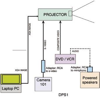
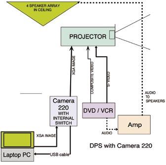
6 6Connect the cables and power source. Tie the power wire in place using wire ties provided. The cables from the projector, should be routed at the work station and connected to the equipment that is desired to produce the necessary pictures. The PC has a 15 pin VGA connector, Camera 101 has an RCA connector that plugs into the RCA side of the S-video adapter (F). The S-video cable (D) then transmits the signal to the projector. The VCR uses the composite cable (E) that has RCA connectors. For additional connection information see the projector user manual. 7Turn the projector on, focus and adjust picture size (with zoom len). Adjust the picture position and tilt using the upper adjustment flange nuts.(r) Lock in position using the flange nuts at the front of the projection plate. Flange nuts (R) 8When projector relamping and/or cleaning of the air filters is required, remove the two lower flange nuts to allow the projector plate to swing down as shown in the following picture. After servicing, swing the projector plate back up into position and replace the nuts. Note, the projector returns back to it s original position and no further adjustment is required. Finished Installation

7 Audio System Installation Currently two audio configurations are available with the projector system. One consist of two self powered speakers that can be placed in the room near the DVD/VCR player. The other option is a amplifier that drives a ceiling mounted speaker array. The audio output is provided by the DVD/VCR unit which has two RCA connectors labeled Audio Out. The cable with RCA connectors plugs into these two jacks. The other end is connected to the 2 RCA jacks on the rear of the amplifirer at the AUX connector, or to the RCA to mini phone adapter which is used to connect the cable to the powered speakers. If an amplifier and ceiling speaker array is employed a lenth of 2 conductor plenum grade speaker cable is also included. The cable connects the ampilifer output ( Com and 4 ohm) to the ceiling mounted array. Speaker array installed in a typical 2 x 2 ceiling panel 50 ft Speaker wire 2 conductor plenum cable Important! Attach speaker safety cable to ceiling grid support. This safety cable must be sufficiently anchored! Attach speaker wire to Com and 4 ohm terminals in the Output section Audio Amp, 15 Watt RCA jacks for inputs. Use AUX jack for the input from the cable. Back of amplifier Installation of the Speaker Array and the amplifier have owners manuals which explains the operation, hook-up and installation of the units.
8 Audio Visual Products Dukane Corporation Audio Visual Products Division 2900 Dukane Drive St.Charles IL, Toll Free (800) Fax (630)
PVM 220 Installation Guide
 R CONFIG SELECT AUDIO AUX INPUT VOICELIFT PAGING SENSOR SENSITIVITY PVM 0 Installation Guide The Extron PVM 0 is an enclosure for the safe mounting of PoleVault system devices in the plenum area of a suspended
PVM 220 Installation Guide
 R CONFIG SELECT AUDIO 1 3 5 2 4 AUX INPUT VOICELIFT PAGING SENSOR SENSITIVITY PVM 220 Installation Guide The Extron PVM 220 is an enclosure for the safe mounting of PoleVault system devices in the plenum
AMPLIFIER A OR B SELECTOR
 M O D E L ABA-1D ABA-1D AMPLIFIER A OR B SELECTOR NILES INSTALLATION & OPERATION GUIDE ABA-1D Speaker/Amplifier Selector S P E A K E R / A M P L I F I E R S E L E C T O R TABLE OF CONTENTS Introduction
LED Flat Panel Installation Instructions For 1 x4, 2 x2, and 2 x4 LED Flat Panels (FP Series)
") LED Flat Panel Installation Instructions For 1 x4, 2 x2, and 2 x4 LED Flat Panels (FP Series) PLEASE READ THESE INSTRUCTIONS BEFORE INSTALLATION PLEASE READ THESE INSTRUCTIONS BEFORE INSTALLATION SAFETY
LED Flat Panel Installation Instructions For 1 x4, 2 x2, and 2 x4 LED Flat Panels (FP Series) PLEASE READ THESE INSTRUCTIONS BEFORE INSTALLATION PLEASE READ THESE INSTRUCTIONS BEFORE INSTALLATION SAFETY
One Circuit Trac System TRAC SECTION, JOINERS & FEEDS T Series
 Project: Fixture Type: Location: Contact/Phone: PRODUCT DESCRIPTION DIMENSIONS Low-Profile, single-circuit trac sections for surface or pendant mounting. I-beam cross section provides added strength and
Installation Instruction
 T F W 604.549.9379 604.549.9555 fluxwerx.com Installation Instruction DRIVER ENCLOSURE Ceiling Type Version Grid Battery Pack GRID MOUNT INSTALL OPTIONS OPTION 1: Standard Vertical Grid drivers can be
ZIP LIGHT LED LUMINAIRE
 LED LUMINAIRE INSTALLATION MANUAL Note: Follow the Electrical Codes of the Country where this fixture will be installed. For Canada follow the Canadian Electrical Code (CE) and for the United States follow
NORTHSTAR 154 BATH/SPA TV. Installation Instructions
 NORTHSTAR 154 BATH/SPA TV Installation Instructions IMPORTANT SAFETY INSTRUCTIONS Must be installed by a qualified electrician Read these instructions. Keep these instructions for future use. Install in
PVM 220 Installation Guide
 R CONFIG SCT DIO X INPUT NORMA VOICIFT NORMA PAGING OR ITIVITY PVM 0 Installation Guide The xtron PVM 0 is an enclosure for the safe mounting of PoleVault system devices in the plenum area of a suspended
Two Circuit Trac System TRAC SECTION, JOINERS & FEEDS
 Project: Fixture Type: Location: Contact/Phone: PRODUCT DESCRIPTION DIMENSIONS Low profile, two-circuit trac sections for surface or pendant mounting. Provides two separate 20-amp circuits from a single
Installation Instructions Studio Makeup Station
 Installation Instructions Studio Makeup Station 30" and 36" Models 5-light 30" Studio Makeup Station 8-light 30" Studio Makeup Station 6-light 36" Studio Makeup Station 9-light 36" Studio Makeup Station
One Circuit Trac System TRAC SECTION, JOINERS & FEEDS T Series
 Project: Fixture Type: Location: Contact/Phone: PRODUCT DESCRIPTION DIMENSIONS Low-Profile, single-circuit trac sections for surface or pendant mounting. I-beam cross section provides added strength and
Assembling a Wall-Mounted CTS
 CHAPTER 3 Revised: February 4, 2010, This chapter provides you with the information you need to assemble a wall-mounted CTS-500-37 and includes the following sections:, page 3-1 Installing the External
INSTALLATION INSTRUCTIONS
 INSTALLATION INSTRUCTIONS Accessory Application Publications No. ELEMENT AII 24282 Issue Date DEC 2002 PARTS LIST 2 Screw-grommets CD Changer Attachment Kit: P/N 08B26-SCV-100 CD changer plate 2 Self-tapping
Internal Joist Mount: ACC120. extension column. Cathedral Ceiling Adapter: ACC556. Mounts to cathedral or vaulted ceilings 120 (+60 ) of adjustment
 of adjustment") Ceiling Plates Ceiling Plate: CMJ470(W), CMJ480(W), CMJ490(W) Internal Joist Mount: ACC120 Round Ceiling Plate: ACC570(S)(W), ACC571 Mounts to wood joists or structural concrete ceiling (requires concrete
Ceiling Plates Ceiling Plate: CMJ470(W), CMJ480(W), CMJ490(W) Internal Joist Mount: ACC120 Round Ceiling Plate: ACC570(S)(W), ACC571 Mounts to wood joists or structural concrete ceiling (requires concrete
Installation Instructions Table of Contents
 Installation Instructions Table of Contents Pre- Installation of Garage Storage Lift 2 Layout the Garage Storage Lift 3 Installing the strut Channels 3 Install the Drive Assembly 5 Install the Drive Shaft
INSTALLATION INSTRUCTIONS
 INSTALLATION INSTRUCTIONS Accessory Application Publications No. CD CHANGER ATTACHMENT KIT 2004 CR-V AII 26118 Issue Date SEP 2003 PARTS LIST CD Changer Attachment Kit (sold separately): P/N 08B26-S9A-100
OFFICE PARTITIONS. Data Port Openings. Use cable tie bracket to dress data cables under panels. STEP 1
 N Power Box Opening Data Port Openings Rear View Front View Remove opening blanks on raceway cover for power and data. If panel contains no electric or data and is used as a pass-thru, leave opening blanks
INSTALLATION INSTRUCTIONS
 INSTALLATION INSTRUCTIONS Universal Short Throw Projector Wall Mount Model: NORTH AMERICA 3130 East Miraloma Avenue Anaheim, CA 92806 USA USA and Canada Phone: 1-800-368-9700 Fax: 1-800-832-4888 Other
PLEASE READ THIS INSTRUCTIONS CAREFULLY, BEFORE YOU START INSTALLATION
 INSTALLATION INSTRUCTIONS PART NUMBER: L0SXC000 DESCRIPTION: 09 ASCENT TRAILER HITCH PLEASE READ THIS INSTRUCTIONS CAREFULLY, BEFORE YOU START INSTALLATION SAFETY PRECAUTION: When installing Trailer Hitch,
INSTALLATION MANUAL. Recessed In-Ceiling Motorized Projection Screen
 INSTALLATION MANUAL Recessed In-Ceiling Motorized Projection Screen IMPORTANT: BEFORE YOU BEGIN To avoid staining or scratching the screen, wash your hands and clean the work area before starting. Do not
SCION im PREMIUM AUDIO Preparation
 SCION im 2016 - PREMIUM AU Preparation Part Number: PT296-12160 (Extension Module w/ AHA) Kit Contents Item # Quantity Reqd. Description 1 1 Extension Module 2 1 BT cable 3 1 DA/Ext Harness 4 1 GPS Antenna
Installation Manual. For. Trident Boat Lifts
 Installation Manual For Trident Boat Lifts Page 2 Safety Precautions 1. Your boat lift is a heavy duty piece of equipment. It is important that all persons that may operate this unit have read and understood
Tools Needed: 7mm Socket socket wrench socket extension interior removal tool wire cutter electical tape Wrangler Raxiom Navigation
 2007-2010 Wrangler Raxiom Navigation Contents: (1) - Raxiom Head Unit (1) - Headphone Jack With Wire (A) (1) - GPS Antennae With Wire (B) (1) - Amplifier Pre-Outs Wire Harness (C) (1) - External Microphone
HID INSTALLATION ON RST1000 Futura
 HID INSTALLATION ON RST1000 Futura Disclaimer: This is a full description of what I have done to my motorcycle. I am in no way suggesting you do as I have done by following these instructions. I have not
Roller Shades CORD LOOP. Head Rail, Fascia and No Head Rail. Installation & Care Instructions
 Roller Shades CORD LOOP Head Rail, Fascia and No Head Rail Installation & Care Instructions 152038 H 5/30/2017 GETTING STARTED A few simple tools are required: - Measuring tape - Power drill, drill bits
PROJECTOR ACCESSORIES
 PROJECTOR *To order select accessories in white or silver, simply add a W for white or an S for silver to the end of the part number. CEILING PLATES CMA100 8" (203 mm) CEILING PLATE WITH ADJUSTABLE 1-1/2"
SL236 INSTALLATION INSTRUCTIONS. SMART-LIFT Electric Ceiling Lift. Instrucciones de instalación Installationsanleitung Instruções de Instalação
 INSTALLATION INSTRUCTIONS Instrucciones de instalación Installationsanleitung Instruções de Instalação Istruzioni di installazione Installatie-instructies Instructions d installation SMART-LIFT Electric
MODELS TSX AND TSX-S SINGLE DUCT ROUND AIR TERMINALS
 MODELS TSX AND TSX-S SINGLE DUCT ROUND AIR TERMINALS INSTALLATION OPERATION & MAINTENANCE New Release Form 130.13-NOM4 (908) In conjunction with the use of these instructions, obtain and refer to the construction,
Two Circuit Trac System TRAC SECTION, JOINERS & FEEDS
 Project: Fixture Type: Location: Contact/Phone: PRODUCT DESCRIPTION DIMENSIONS Low-Profile, two-circuit trac sections for surface or pendant mounting. Provides two separate 20-amp circuits from a single
SPACESAVER EC-300 A ELECTRICS
 INSTALLATION INSTRUCTIONS SPACESAVER EC-300 A ELECTRICS SECTION I TOP MOUNTED ELECTRICS SECTION II FACE PANEL MOUNTED ELECTRICS SECTION III ZFS INSTALLATION INSTRUCTIONS This symbol indicates a connection
TOYOTA im NAVIGATION UPGRADE Preparation
 Preparation Part Number: PT296-00170 PT296-12170 (Extension Module w/ AHA) Kit Contents Item # Quantity Reqd. Description 1 1 Extension Module 2 1 BT cable 3 1 DA/Ext Harness 4 1 GPS Antenna kit 5 6 Bolt
PFadvantage JD 3300/4400/6600/7700; 4420
 Ag Leader Technology Combine Installation JD 33//66/77; 2 Note: Indented items indicate parts included Quantity by Model in an assembly listed above Early Late Part Name/Description Part Number 3 3 6 6
MODELS SGX AND SSX SINGLE DUCT ROUND AIR TERMINALS
 BY JOHNSON CONTROLS INSTALLATION OPERATION & MAINTENANCE MODELS SGX AND SSX SINGLE DUCT ROUND AIR TERMINALS New Release Form ET130.13-NOM4 (908) In conjunction with the use of these instructions, obtain
MEDIA LED. Pendant Standard Mount Installation ou de montage WARNING:
 MEDIA LED Pendant Standard Mount WARNING: Disconnect main power at the source prior to installation! Thread gripper base onto 1 /4 20 stud, or with #8 screw. Depress gripper nozzle to insert aircraft cable.
INTEGRID TRACK (120V) SPECIFICATIONS
 SPECIFICATIONS") INTEGRID TRACK (120V) SPECIFICATIONS GENERAL Integrid Track shall be a combination Track and main runner for mech - anically supporting suspended ceiling systems. Integrid Track shall allow fixtures to
INTEGRID TRACK (120V) SPECIFICATIONS GENERAL Integrid Track shall be a combination Track and main runner for mech - anically supporting suspended ceiling systems. Integrid Track shall allow fixtures to
= Experienced
 I N S T A L L A T I O N G U I D E APPLICATION LENGTH MODEL YR PART # Ford F-250 / F-350 / F-450 Regular Cab * (48 ) 2002-2003, 2008-2012 75134-01A Ford F-250 / F-350 / F-450 Super Cab * (60 ) 2002-2003,
k" or #8 nut driver A pair of regular pliers can substitute for the nut drivers but will
 Page of 3 ARIES SYSTEM 300 MUSIC SYNTHESIZER Module AR-38 STEREO REVERB & OUTPUT ASSEMBLY INSTRUCTIONS The previous pages were written as a general guide to familiarize the builder with the components.
INSTALLATION INSTRUCTIONS
 INSTALLATION INSTRUCTIONS Accessory Application Publications No. 2003 ELEMENT AII 24318 Issue Date DEC 2002 PARTS LIST Trailer Hitch Kit P/N 08L92-SCV-100 4 Bolts, 12 x 35 mm Trailer hitch U-bolt 2 Nuts,
INSTALLATION INSTRUCTIONS
 INSTALLATION INSTRUCTIONS Accessory Application Publications No. AII 27367 HITCH 2005 ODYSSEY Issue Date DEC 2004 NOTE: An optional heavy-duty power steering cooler, ATF cooler and air duct are required
TOYOTA PRIUS FOG LIGHT (Halogen or LED)
") Part Number: TPR-413 / TPR-813 Kit Contents Item # Quantity Reqd. Description 1 2 Fog Lamps 2 1 Lower Grill 3 1 Switch Assembly 4 1 Fog Light Operation guide 5 1 Harness Bag Hardware Bag Contents Item
Part Number: TPR-413 / TPR-813 Kit Contents Item # Quantity Reqd. Description 1 2 Fog Lamps 2 1 Lower Grill 3 1 Switch Assembly 4 1 Fog Light Operation guide 5 1 Harness Bag Hardware Bag Contents Item
INSTALLATION INSTRUCTIONS
 INSTALLATION INSTRUCTIONS Accessory Application Publications No. BII 25830 2004 MDX Issue Date SEP 2003 PARTS LIST 2 Clips Trailer Hitch Kit: P/N 08L92-S3V-200A Receiver cover Trailer hitch Harness Kit:
ComfortPoint Programmable Lon, VAV/Unitary Controllers
 ComfortPoint Programmable Lon, VAV/Unitary Controllers Controller Model Programmable Type Universal Inputs (UI) Table 1. Controller configurations. Digital Inputs (DI) PRODUCT DESCRIPTION INSTALLATION
SAFETY INSTRUCTIONS Before installation and operation, read these instructions carefully and use this product only in the manner described by the manu
 Installation Manual RANGE HOOD MODEL: BUF-07W BUF-07P BUF-07W/P TABLE OF CONTENTS Safety Instructions... 2, 3 Name of Parts... 4 Circuit Diagram... 4 Dimensions/Accessories... 5, 6 Range Hood Location...
 INSTALLATION INSTRUCTIONS Accessory Application Publications No. AII 38133-38406 HITCH 2008 ODYSSEY Issue Date NOV 2007 NOTE: A required heavy-duty power steering cooler, ATF cooler and air duct are required
INSTALLATION MANUAL ELECTRIC DOUBLE OVEN RANGE
 ENGLISH ESPAÑOL INSTALLATION MANUAL ELECTRIC DOUBLE OVEN RANGE Please read these instructions thoroughly before installing and operating the range. LDE3019ST LDE3017ST LDE3017SB LDE3017SW LDE3015ST LDE3015SB
2015 Mustang Lightbar (All Models) CDC#
 CDC#") 2015 Mustang Lightbar (All Models) CDC# 1511-7000-01 Components: 1 CDC Lightbar Note: READ instructions before starting installation!!! CDC Part# Driver side bracket 0511-6001-05 Passenger side bracket
2015 Mustang Lightbar (All Models) CDC# 1511-7000-01 Components: 1 CDC Lightbar Note: READ instructions before starting installation!!! CDC Part# Driver side bracket 0511-6001-05 Passenger side bracket
INSTALLATION INSTRUCTIONS
 INSTALLATION INSTRUCTIONS Accessory Application Publications No. in- ENTERTAINMENT SYSTEM 2004 TSX BII 24811 Issue Date APRIL 2003 PARTS LIST Attachment Kit P/N 08B23-SDA-101A Monitor bracket harness FM
INSTALLATION INSTRUCTIONS
 INSTALLATION INSTRUCTIONS Accessory Application Publications No. AII 26042-26353 XM INTERFACE ODYSSEY EXCEPT EX-L WITH NAVI/RES Issue Date FEB 2004 PARTS LIST 8 Wire ties XM Radio Attachment P/N 08B15-S0X-100
VOH681A Drop Down Video Monitor VOH682A Drop Down TV / Video Monitor OPEN. Installation Guide
 VOH681A Drop Down Video Monitor VOH682A Drop Down TV / Video Monitor ON OFF AUTO OPEN Installation Guide Important Notice It is unlawful in most jurisdictions for a person to drive a motor vehicle which
The POWER. In PRESENTATION PRODUCTS. Instruction Book for BOARDROOM ELECTROL DA-LITE SCREEN COMPANY, INC.
 The POWER In PRESENTATION PRODUCTS Instruction Book for BOARDROOM ELECTROL DA-LITE SCREEN COMPANY, INC. 3100 North Detroit Street Post Office Box 137 Warsaw, Indiana 46581-0137 Phone: 574-267-8101 800-622-3737
INSTALLATION INSTRUCTIONS
 INSTALLATION INSTRUCTIONS Accessory HITCH Application 2009 CR-V Publications No. AII 40373 Issue Date AUG 2008 PARTS LIST Plain washer, 12 mm Trailer Hitch Kit P/N 08L92-SWA-100 Trailer hitch 6 Spring
Part Name/Description Part Number Quantity Instruction Kit Metalfor Flow Sensor
 NOTE: Indented items indicate parts included in an assembly listed above Part Name/Description Part Number Quantity Instruction Kit Metalfor 4101091 1 Flow Sensor 4001356 1 Deflector plate 2000612-1 1
INSTALLATION INSTRUCTIONS
 INSTALLATION INSTRUCTIONS Universal Short Throw Projector Wall Mount Model: UNI/UNIE NORTH AMERICA 3130 East Miraloma Avenue Anaheim, CA 92806 USA USA and Canada Phone: 1-800-368-9700 Fax: 1-800-832-4888
INSTALLATION INSTRUCTIONS
 TABLE OF CONTENTS GENERAL...2 SPECIFICATIONS...2 PACKAGE CONTENTS...2 PACKAGE CONTENTS: ACCESSORIES...3 REQUIRED TOOLS...3 ADD-ON COMPONENTS...3 CABINET MOUNTING HAND-HOLE OR VAULT...3 CABINET MOUNTING
HCB-8 AFTER BLENDING. Servoreeler vertical cradle support Registration slots in adapter bracket
 HCB-8 Hard Ceiling Box 8 Square Access Door Ceiling Box Assembly permits the installation of an SRL-8 Servoreeler above a sheetrock or other permanent ceiling structure. The HCB-8 provides service access
Digitrip Retrofit System for ITE K-3000, K-3000 S, K-4000 and K-4000 S Breakers
 Supersedes IL 33-858-4 Dated 05/02 Digitrip Retrofit System for ITE K-3000, K-3000 S, K-4000 and K-4000 S Breakers Digitrip Retrofit System for ITE K-3000, Digitrip Retrofit System for ITE K-3000, K-3000
This symbol indicates information that, if ignored, could possibly result in personal injury or even death due to incorrect handling.
 Installation Guide Safety Instructions For your safety, read all the instructions in this guide before using the mounting bracket. Incorrect handling that ignores instructions in this guide could damage
PFadvantage Metalfor Araus 1360
 Metalfor Araus 1360 Note: Indented items indicate parts included in an assembly listed above Part Name/Description Part Number Quantity Instruction Kit Metalfor Araus 2005300-14 1 Display Bracket 4000134
Replacing the Gear Drive Motor Assembly and GFCI Module for Operation with the Chain Drive Motor Assembly
 Replacing the Gear Drive Motor Assembly and GFCI Module for Operation with the Chain Drive Motor Assembly Kit Contents B00009035-3 Motor Drive Assembly (Return original to CMI) B00007698-8 GFCI Module
Lexion 570R/575R, 580R/585R, 590R/595R
 Note: Indented items indicate parts included in an assembly listed above Quantity by Model 2006+ All Years Part Name/Description Part Number 570R 575R 580R 585R Instruction Kit Lexion 570/580/590 2005500-5
INSTALLATION INSTRUCTIONS:
 INSTALLATION INSTRUCTIONS: The CA-5030 is an ultrasonic parking assist system designed for use on the rear bumper of most cars and trucks. This system detects any people or objects behind the vehicle using
In-ceiling mount NDA-FMT-DOME. en Installation manual
 In-ceiling mount NDA-FMT-DOME en Installation manual In-ceiling mount Table of Contents en 3 Table of contents 1 Safety 4 1.1 Safety message explanation 4 2 Installation Overview 5 3 Installing a Recessed
Job Sheet 1 Installing the Net Watt-Hour Meter
 Job Sheet 1 Installing the Net Watt-Hour Meter Net kwh Meter The Grid-Tie Training System optional net meter is a 100 140 V AC, single-phase, two-wire, bidirectional triple element watt-hour (Wh) meter
PRELIMINARY INSTALLATION INSTRUCTIONS. PARTS LIST Security System Kit (sold separately) P/N 08E51-EP4-101
 P/N 08E51-EP4-101") INSTALLATION INSTRUCTIONS Accessory Application Publications No. All 30510 (LX) 2006 PILOT Issue Date SEP 2005 PARTS LIST Security System Kit (sold separately) P/N 08E51-EP4-101 Security system control
INSTALLATION INSTRUCTIONS Accessory Application Publications No. All 30510 (LX) 2006 PILOT Issue Date SEP 2005 PARTS LIST Security System Kit (sold separately) P/N 08E51-EP4-101 Security system control
Jeep Wrangler 4.0 Liter TJ Jeep Wrangler 2.5 Liter TJ Installation instructions
 TM www.jeepair.com 1999 Jeep Wrangler 4.0 Liter TJ 1999-2001 Jeep Wrangler 2.5 Liter TJ Installation instructions Kit Information After 1994 every vehicle was designed for R134a refrigerant. The Jeep kit
TOYOTA VENZA 2009 TRAILER WIRE HARNESS Procedure
 Part Number: PT791-0T099 Kit Contents Item # Quantity Reqd. Description 1 1 Trailer Wire Harness Module 2 1 4-Flat Harness 3 1 Battery Power Wire Harness 4 1 Mounting Bracket, 4-Flat 5 2 Screw #10-24 6
INSTALLATION GUIDE FOR STAINLESS STEEL SPREADER CONVERSION KIT SNOWRATOR
 2017 INSTALLATION GUIDE FOR STAINLESS STEEL SPREADER CONVERSION KIT SNOWRATOR AES L. T. RICH PRODUCTS 11/15/2017 TABLE OF CONTENTS 1.0 SHIPPING CONTENTS... 2 2.0 IMPORTANT INFORMATION... 3 2.1 PURPOSE...
SUT-450-I ASSEMBLY REQUIREMENTS
 SUT-450-I Torque wrench, carpenters square, wire cutters, Phillips screwdriver, 7/16, 9/16, and 3/4 combination wrenches, ratchet, 9/16,3/4,13/16, and 7/8 sockets. ASSEMBLY REQUIREMENTS *Torque all T-bolt
Conflicts. TOYOTA Prius Foglights. Part Number: Accessory Code: LF1. Factory Fog Lights
 TOYOTA Prius 2011- Foglights Part Number: 00016-47401 Accessory Code: LF1 Conflicts Factory Fog Lights Item # Quantity Reqd. Description 1 2 Fog Lamps 2 2 Fog Lamp s bezels 3 1 Switch Assembly 4 1 Fog
INSTALLATION INSTRUCTIONS FUEL SURGE TANK KIT
 INSTALLATION INSTRUCTIONS FUEL SURGE TANK KIT BMW E46 3-Series, Excl Convertible Document: 19-0056 Support: info@radiumauto.com Relieve fuel pressure in vehicle before beginingthe installation. Disconnect
Installation Instructions
 Installation Instructions Speedcook Oven Read carefully. Keep these Instructions. INSTALLATION INSTRUCTIONS Electrical Requirements Product rating is 240/208 volts AC, 60 Hertz, 30 amps and 6.5 kilowatts.
INSTALLATION GUIDE INSTALLATION GUIDE
 INSTALLATION GUIDE INSTALLATION GUIDE Technical Specifications READ AND SAVE THESE INSTRUCTIONS Check the fan label to make sure it is the correct voltage. Operating voltage Diameter Weight Operating frequency
TBX10A INSTALLATION/OWNER'S MANUAL 10" Sealed Enclosure with Built-in Amplifier
 TBX10A INSTALLATION/OWNER'S MANUAL 10" Sealed Enclosure with Built-in Amplifier Getting Started Thank you for purchasing the Dual TBX10A 10" ported enclosure with built-in amplifier. Although Dual has
Installation Manual. For. Alumavator / Platinum Boathouse Lifts
 Installation Manual For Alumavator / Platinum Boathouse Lifts Page 2 Safety Precautions 1. Your boat lift is a heavy duty piece of equipment. It is important that all persons that may operate this unit
HP BladeSystem c7000 Carrier-Grade Options Installation Guide
 HP BladeSystem c7000 Carrier-Grade Options Installation Guide Part Number 5991-8062 September 2009 (Second Edition) Copyright 2009 Hewlett-Packard Development Company, L.P. The information contained herein
ONBOARD AIR HOOKUP KIT
 ONBOARD AIR HOOKUP KIT PART NO. 20052 (30 amp - 110PSI on, 150PSI off) PART NO. 20053 (30 amp - 85PSI on, 105 PSI off) PART NO. 20055 (30 amp - 90 PSI on, 120 PSI off) IMPORTANT: It is essential that you
Important! The subwoofer system is designed to be used only with the rear seat in the up position only.
 Important! The subwoofer system is designed to be used only with the rear seat in the up position only. CONTENTS 1EA. SUBWOOFER ASSEMBLY 2EA. BRACKET LOWER 2EA. BRACKET UPPER 1EA. OVERLAY HARNESS 2EA.
UNPACK AND IDENTIFY THE FOLLOWING PARTS.
 SUT-250-M2 ASSEMBLY REQUIREMENTS *Torque all T-bolt nuts to 35-40 foot pounds. *Check all lights before towing. *Tire pressure not to exceed recommendation on serial tag. *Re-torque wheel nuts after first
CENTRAL VACUUM SYSTEMS
 CENTRAL VACUUM SYSTEMS INSTALLATION INSTRUCTIONS Review this manual before installing the central vacuum system Dynovac Industries 1 800 226 1221 1 403 346 4877 #1, 6841 52 Avenue Red Deer, Alberta T4N
AQUASONIC POOL SPEAKER INSTALLATION GUIDE
 AQUASONIC POOL SPEAKER INSTALLATION GUIDE Clark Synthesis, Inc. 8020 Southpark Circle, Suite 600 Littleton, CO 80120 www.clarksynthesis.com 800-898-1945 ! Thank GENERAL SAFETY INSTRUCTIONS you for purchasing
COLD WEATHER START KIT Platinum Mini Split
 COLD WEATHER START KIT Platinum Mini Split Cold Weather Start Kit: To be used in conjunction with Platinum Mini Split cooling system. The Coolest Thing In Wine Storage LASS.MPS 051515 Conforms to ANSI/UL
SlamPak SLPK-CAN-SPYDER1 SKU#94491& I n s t a l l a t i o n G u i d e for the
 SlamPak I n s t a l l a t i o n G u i d e for the SLPK-CAN-SPYDER1 SKU#94491& 94490 If you choose to perform the installation yourself, it is absolutely vital that the Stealthbox be properly mounted to
Circa Ambient Interior Luminaire
 IMPORTANT SAFETY INSTRUCTIONS 1. Read carefully before installing fixture. Retain for future reference. To prevent electrical shock, turn off electricity at fuse box before proceeding. 2. Failure to follow
INSTALLATION MANUAL. Melink Corporation (513) Revision
 Revision") INSTALLATION MANUAL Revision 130711 Table of Contents Step Installation Contractor Page 1 Install System Controller Electrical 4 2 Install Variable Frequency Drive Electrical 6 3 Install Touchpad Mechanical
INSTALLATION MANUAL Revision 130711 Table of Contents Step Installation Contractor Page 1 Install System Controller Electrical 4 2 Install Variable Frequency Drive Electrical 6 3 Install Touchpad Mechanical
Jeep Wrangler TJ. Complete Air Conditioning System. Slide Control Head. Installation instructions
 WWW.JEEPAIR.COM 1996-1998 Jeep Wrangler TJ Complete Air Conditioning System Slide Control Head Installation instructions Kit Information After 1994 every vehicle was designed for R134a refrigerant. The
S/6EA CARRIAGE & ELECTRICAL INSTALLATION INSTRUCTIONS PART VI CARRIAGE ASSEMBLY ELECTRICAL WIRING PART III THE FESTOON RACKING ELECTRICAL HOOK-UPS
 S/6EA CARRIAGE & ELECTRICAL INSTALLATION INSTRUCTIONS PART I CARRIAGE ASSEMBLY PART II ELECTRICAL WIRING PART III THE FESTOON PART IV RACKING PART V ELECTRICAL HOOK-UPS PART VI MISCELLANEOUS This symbol
ELECTRICAL SYSTEM UPGRADE
 NEW CONTROLLER & ELECTRICAL SYSTEM UPGRADE FOR DAIRY TECH, INCORPORATED 10, 30 & 60G PASTEURIZERS Parts to Include 2 Wire ties (Nuts) 2 sticky wire mount pads Large Rubber Grommet (for bottom of electric
SCION xd INTERIOR LIGHTING UPGRADE Preparation
 Preparation Part Number: PTS21-52085 Light Guide Kit Contents Item # Quantity Reqd. Description 1 1 Controller Board, 4 color programmed w/ Bracket 2 1 RGB, LED Engine wire harness 3 2 14mm Light Rod,
The POWER. In PRESENTATION PRODUCTS. Instruction Book for COSMOPOLITAN ELECTROL For Sizes Up To 9'x12' DA-LITE SCREEN COMPANY, INC.
 The POWER In PRESENTATION PRODUCTS Instruction Book for COSMOPOLITAN ELECTROL For Sizes Up To 9'x12' DA-LITE SCREEN COMPANY, INC. 3100 North Detroit Street Post Office Box 137 Warsaw, Indiana 46581-0137
TOYOTA SIENNA TRAILER WIRE HARNESS Preparation
 Preparation Part Number: PT791-08150 (non-se) PT791-08102 (SE only) Kit Contents Item # Quantity Reqd. Description 1 1 Trailer Module Harness 2 1 4-Flat Harness 3 1 Battery Power Wire Harness 4 1 Mounting
Part Number: TRA-316/TRA-816
 Date: 07.29.2016 TOYOTA RAV4 2016- FOG LIGHT (Halogen/LED) Part Number: TRA-316/TRA-816 Kit Contents Item # Quantity Reqd. Description 1 2 Light Housings 2 2 Light Bezels 3 1 Wire Harness Bag* 4 1 Connector
Handyman Motor Capacitor Meter PART NO
 Handyman Motor Capacitor Meter PART NO. 2225174 To test a motor-run capacitor in the field with no capacitance meter at hand, you had to hook up the capacitor through an extension cable to a 120V wall
SR-T5 LINE ARRAY SPEAKER. WALL PAN BRACKET (optional) SR-PB5 OPERATING INSTRUCTIONS
 SR-PB5 OPERATING INSTRUCTIONS") OPERATING INSTRUCTIONS LINE ARRAY SPEAKER WALL PAN BRACKET (optional) SR-T5 SR-PB5 Thank you for purchasing TOA's Line Array. Please carefully follow the instructions in this manual to ensure long, trouble-free
OPERATING INSTRUCTIONS LINE ARRAY SPEAKER WALL PAN BRACKET (optional) SR-T5 SR-PB5 Thank you for purchasing TOA's Line Array. Please carefully follow the instructions in this manual to ensure long, trouble-free
Electrical Applications. Metal Framing & Cable Tray Superstrut Metal Framing System. Column A. Design Data: Materials: Column B
 Electrical Raceway Series 800 Surface Raceway and Lighting Systems Superstrut channel together with snap-in closure strip is listed by Underwriters Laboratories as a surface metal raceway. Other accessories
CyberDome Series. Installation Manual
 CyberDome Series Installation Manual Copyright Disclaimer Trademarks and patents Intended use FCC compliance Copyright 2006, GE Security Inc. All rights reserved. This document may not be copied or otherwise
INSTALLATION INSTRUCTIONS
 INSTALLATION INSTRUCTIONS Accessory USB ADAPTER Application 2014 INSIGHT Publications No. AII 50655 Issue Date OCT 2013 PARTS LIST USB Adapter Attachment Kit P/N 08B28-TM8-100A 6 mm Flange nut Control
SADDLEBAG LID SPEAKER KIT TMS69BL H-D. Installation & Operation. Installation assistance available at:
 Installation assistance available at: www.rockfordfosgate.com/rftech 600 South Rockford Drive Tempe, Arizona 85281 United States Direct: (480) 967-3565 Toll Free: (800) 669-9899 ROCKFORDFOSGATE.COM 1998-2013
GN-3A Polaris General SSV Works 3 Speaker Audio Kit
 GN-3A Polaris General SSV Works 3 Speaker Audio Kit pg 2 Disassembly, Wire and Amplifier Plate Installation pg 9 Glovebox Subwoofer Installation pg 17 Kick Panel Speakers Installation pg 21 MRB3 and Dash
TOYOTA VENZA 2009 TRAILER WIRE HARNESS Procedure
 Part Number: PT791-0T099 Kit Contents Item # Quantity Reqd. Description 1 1 Trailer Wire Harness Module 2 1 4-Flat Harness 3 1 Battery Power Wire Harness 4 1 Mounting Bracket, 4-Flat 5 2 Screw #10-24 6