The Reaper Owners Manual Foreword Warning!!! Never Never Stall Speed Stall Speed Chart
|
|
|
- Anthony Perry
- 6 years ago
- Views:
Transcription
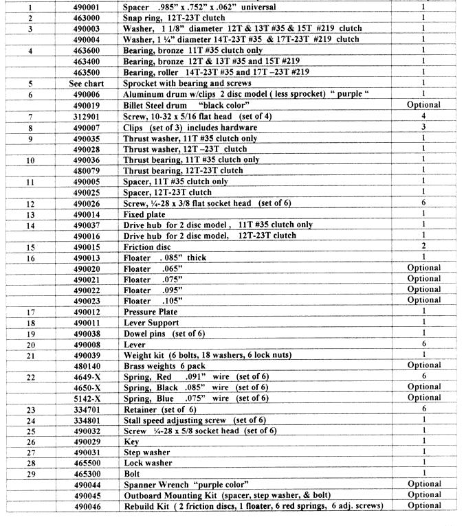
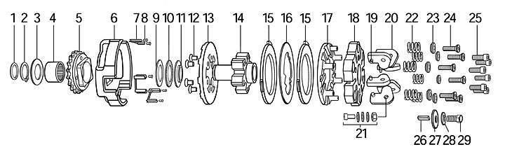
1 The Reaper Owners Manual Foreword The Reaper is a centrifugal disc clutch designed to mount on a ¾ crankshaft or jackshaft for race karts with engines up to 20hp. This manual will help you gain maximum performance as well as longevity of the components. This is a racing clutch and should not be used in any application other than kart racing. Aluminum drum is for use in stock and super stock classes. Steel drum is required on jackshaft mounting for 2 stroke racing and in limited and limited mod classes in 4 stroke racing. The Reaper clutch features Cryogenic treatment to all critical components for superior performance, cooling, and longevity. Warning!!! When engine starts the clutch and chain may spin at high speeds if brake is not applied. Never operate vehicle without proper guards in place. Never attempt to adjust, repair, or lubricate clutch with engine running. Stall Speed Stall speed is the RPM that the clutch locks up solid. For top performance it is important to adjust the clutch stall speed to match the peak torque of the engine. This allows the engine to operate within its maximum power band for quicker acceleration. Stall Speed Chart Prior to installing the clutch onto the engine it is important to install the correct weight and spring combination for the class. The chart is a guideline only as various weight/spring combinations can produce comparable results. Note: Steel Drum required on Jackshaft mounted clutch and Ltd mod and mod engines Class weight spring stall speed range initial spring height Rookie/Turquoise 3 washers WKA purple/ikf Jr1 Canadian Honda 4 washers WKA blue restrictor 3 washers WKA Gold / IKF Jr2 3 washers Stock 5hp Flat Head and OHV Briggs 3 washers Super Stock/Controlled Stock 2 washers Limited / Limited Mod Lever only cycle w/jackshaft 4 washers ,000-10, Installation When space allows it is better to mount the clutch inboard (sprocket facing engine) because spring adjustment can be accomplished without removing the clutch. Mounting the clutch outboard requires the optional spacer kit p/n for proper clearance between the levers and the side of the engine. Steps for inboard installation 1. apply a thin coat of anti-seize grease to the crankshaft 2. slide spacer (item 1) onto crankshaft the spacer provides proper clearance between the chain and the side cover of the engine 3. insert key (item 26) into keyway of clutch key must slide freely into keyway file any nicks or burrs from crankshaft or keyway in clutch if necessary. 4. slide clutch onto crankshaft be sure to align keyway in crank with key in clutch 5. install stepped washer (item 27), lock washer(item 28), and bolt(item 29) tighten to 150 in lbs optional Spanner Wrench (p/n ) is available to hold clutch in place during tightening process the Spanner Wrench also comes in handy when disassembling the clutch during maintenance 1

2 Stall Speed Adjustment Adjusting the stall speed of the clutch may be intimidating if you are a newcomer to the sport however it is quite easy. A tachometer with memory is needed to obtain accurate data. Matching your clutch stall speed to the engines torque peak to rpm above should produce the best lap time. Start testing with the stall speed on the low side of the chart in order to obtain a base time. Then make adjustments to the clutch to find the quickest lap time. Steps 1. Install the correct weight and spring for the class from the Stall Speed Chart 2. Go onto the track and observe tachometer reading as kart is accelerating. The stall speed is the reading when the clutch engages solid and the kart begins accelerating rapidly. If the stall speed is far above the range on the chart you must exit the track immediately in a safe manner and return to the pits to adjust the stall speed lower in order to prevent overheating the clutch. If the stall speed is within the range on the chart you may drive enough laps to get the engine up to proper temperature and get yourself comfortable with the track configuration. Run about five to ten clean laps to establish your base time. Return to the pits and look at the tachometer s memory to note data. Note the Max RPM, MPH, lap time and the stall speed. Adjust the stall speed and make another track test to see if lap times are improving. Keep making adjustments and track tests to determine the best stall speed for the fastest lap time. Now you know the upper limit of stall speed for your engines power. How to Raise Stall Speed There are three ways to raise the stall speed of the Reaper clutch. 1 st Spring Adjustment (clockwise) 2 nd Less Weight on levers (remove washer(s) 3 rd Use stronger springs To increase the preload on the springs for higher stall speed dial the adjusting screws (item 24) clockwise. Adjust all six springs an equal amount in order to balance the load uniformly. ½ turn will raise the stall speed about 150 rpm. Results will vary due to different power ranges. If you can t get the correct stall speed within the spring adjustment limits (Fig 1) then remove weight (item 21) from the levers or install stronger springs. How to Lower Stall Speed ( Three ways) 1st Decrease the preload of the springs by dialing the adjusting screws (item 24) equally counterclockwise. ½ turn out will lower stall speed about 150 rpm. 2nd Install optional springs (item 22) that have a smaller wire size 3rd Add weight to the levers (item 21) note: excessive weight does not improve performance and in fact is counterproductive is certain situations. Too much weight can cause chatter during acceleration. Stall Speed Adjustment Limits Warning!!! The compression springs in this clutch have a finite range of travel therefore adjustment limits (Fig.1) must be observed. Never adjust above the maximum height of.295 because the adjusting screws may back out. Never adjust below the minimum height.245 in order to prevent coil bind. Coil bind is when the spring coils are fully compressed and the spring acts like a solid object with zero movement. Coil binding of the springs therefore can prevent the pressure plate (item 17) from moving the prescribed distance to allow complete lock up of the clutch and excess heat will quickly ruin the clutch. Measure from top of retainer to top of lever support. 2


 2. Remove outer thrust washer (item 2) 3.")
 from lever support (See AA) 7. Remove lever support (item 18) to gain access to friction discs.")
3 Air Gap Air gap is the space between the clutch discs. Correct air gap will allow a neutral mode for starting the engine and allow the levers to pivot the prescribed amount for firm lock up. The air gap is preset at.032 +/-.005 and needs to be checked during feeler gauge maintenance. As friction discs wear the air gap will increase. Do not allow air gap to exceed.050 as clutch may chatter. Do not decrease air gap below.028 as clutch will not lock up aggressively. Note: optional floaters are available to adjust air gap. Measure air gap with a feeler gauge between the pressure plate and the top lining. Chatter The friction material is very aggressive therefore some chatter may occur when leaving the grid. On the race track the chatter will go away. Excessive air gap, glazed friction discs, or too much weight on the levers can contribute to chatter. Before each track session a light spray of WD-40 will reduce chatter and corrosion. Disassembly 1. Remove snap ring (item 1) 2. Remove outer thrust washer (item 2) 3. Remove drum and sprocket assembly (item 6) 4. Remove thrust washer, bearing, and spacer (item 9, 10, & 11) 5. Remove springs, retainers, & adjusting screws (item 22,23, & 24) 6. Remove bolts (item 25) from lever support (See AA) 7. Remove lever support (item 18) to gain access to friction discs. AA BB Note: Do not remove fixed plate (item 13) from drive hub (item14) (see BB) unless you are installing a new plate. Reason; they are attached and ground as a unit for precision. Maintenance A racing clutch is subject to heat, vibration, and constant stress during a race event. Cleaning and lubricating bearings is necessary after every race event for peak performance. Aluminum Drum/Sprocket (item 5&6) Important! check the four flat head screws A for tightness. If loose remove and apply blue loctite B to threads then install back into drum. Inspect the six clip screws B for tightness and retighten if needed. Inspect clips C replace when deep grooves are evident where discs make contact. Inspect teeth on sprocket and replace when worn out. A C 3
 A true pressure plate is important for top performance. Inspect the ground surface for warp or glaze.")


4 Note: Apply light heat to screw to melt loctite before removal. Drive hub (item 14) The drive hub is made to last a long time. Periodically check for wear or cracks in keyway and replace if necessary. Pressure Plate (item 17) A true pressure plate is important for top performance. Inspect the ground surface for warp or glaze. A shiny glaze appearance can be removed by sanding with medium grit sandpaper. If the pressure plate is warped it should be replaced. New pressure plates come with Cryogenic treatment to cool better, increase strength, and improve engagement over a reground pressure plate. Friction Discs (item 15) The most important component in the clutch. Factory original discs have cryogenic treatment for longer wear, better cooling, and consistent performance. Do not risk ruining your clutch with inferior knock off discs as your clutch will overheat and not lock up correctly for peak performance. Insist on genuine Horstman discs. Replace discs when worn to.120 thick. Inspect the three lugs on the perimeter of the disc and replace if excessively worn. After every 3-5 races lap the discs on a flat surface to remove glaze. Use medium 100 grit sandpaper. Lapping should be accomplished in about 30 seconds per side. Use a figure eight motion when lapping. flat surface Sandpaper Genuine Reaper/Horstman Disc 12 equally spaced grooves copper/tan color Floater (item 16) Check periodically for warp or glaze. If surface has a shiny glazed appearance the floater can be lapped. Follow instructions as per friction discs. Also note the floater is cryogenic treated and a new floater performs better than a lapped used floater. Lever Support (item 18) The lever support is made from hard coated aircraft alloy aluminum and will last a long time. Check for wear on the sides of the slots that come in contact with the levers. When slots are deeply worn replace. Levers (item 20) The levers are made from hardened alloy steel and will last a long time. It is important to apply anti-seize grease to the dowel pins to reduce friction and wear every time you maintain the clutch. After many races the pivot holes in the lever(s) will elongate from wear and replacement will be necessary. Dowel Pins (item 19) Subject to high stress and wear. Replace every twenty race events. Apply anti-seize lube to dowel pins during periodic maintenance. Springs (item 22) Horstman springs are cryogenically treated at -310 F to increase longevity up to 300%. Springs are subjected to heat and stress and must be checked every five races. When length is below.475 replace with genuine Horstman springs. Warning! Aftermarket springs are not cryogenically treated nor in most cases shot peened or made from the correct alloy. Aftermarket springs will make you clutch inconsistent as they weaken prematurely under heat and pressure. 4

 and install")


5 Assembling Clutch 1. Apply anti-seize or grease to dowel pin(s) and install into lever(s) 2. Insert levers w/pins into slots of lever support 3. Install Pressure Plate 4. Install screws ¼-28 x 5/8 socket head cap screws (item 25) 5. Place 1 st friction disc onto hub 6. Place Floater over 1st friction disc 7. Place 2 nd Friction disc over floater 5
 with holes")


 Apply a light coat of")

6 8. Set top assembly onto hub align bolts (item 25) with holes in hub 9. Thread screws into hub and tighten to 150 in lbs. Sequence Insert springs and adjust uniformly 11. Flip unit over and install spacer (item 11) Apply a light coat of grease to spacer 12. Place thrust bearing onto hub and apply a light coat of grease 13. Place thrust washer onto hub and apply a light coat of grease 6


 Apply light coat of lithium")


7 14. Slide drum onto hub align lugs in discs with drum slots. Apply grease to bearing before assembly 15. Install outer thrust washer (item 3) Apply light coat of lithium grease. 16. Install Snap Ring 17. Check end play Minimum.010 Maximum.035 Measure space between snap ring and Washer. Note: Optional Wrench p/n is handy for disassembly, assembly, and holding clutch in place when tightening clutch bolt (item 29) 7
8 8
HORSTMAN GREASED LIGHTNING CLUTCH
 HORSTMAN GREASED LIGHTNING CLUTCH Horstman s Greased Lightning (GL) clutch is designed for ultra high performance, and requires expert setup and a serious commitment to maintenance. Warning!!! 1. Clutch
Stellar 4 Clutch Manual
 INSTRUCTIONS Stellar 4 Clutch Manual Thank you for choosing Tomar products; we are proud to be your manufacturer of choice. Please read this instruction sheet carefully before beginning installation, and
Drill pattern for engine mount
 2006 A CONTENTS OF KIT Each HPV100 engine is delivered with the following components: Quantity Description 1 Sparkplug cap 1 Sparkplug (NGK BR10EG) 1 Exhaust System 2 Exhaust springs 1 Carburetion phenolic
FOR VIDEO INSTRUCTIONS GO TO P.N IRP TRIPLE GRIP CLUTCH MANUAL KTM 50cc
 P.N. 90360 IRP TRIPLE GRIP CLUTCH MANUAL KTM 50cc 009-05 INSTALLATION STEPS: Optional Clutch Cover 9039 available wider for more oil capacity no grinding required INSIDE OF STOCK KTM COVER 009- MUST BE
 DRUM BRAKE RIMS Periodic inspection of drum brake rims is necessary to determine indications of uneven or excessive wear. In general, brake rim failures other that regular wear are caused by brake linings
70001 and Clutch Rebuild Instructions
 70001 and 70010 Clutch Rebuild Instructions Brinn, Incorporated 1615 Tech Drive Bay City, MI 48706 Telephone 989.686.8920 Fax 989.686.6520 www.brinninc.com Notice Use these instructions if you only want
Clutch Installation Guide
 Clutch Installation Guide 0 STOP! READ CAREFULLY BEFORE INSTALLING CLUTCH This clutch must be installed by a qualified installer. Improper installation or failure to replace or resurface the flywheel,
Self-Adjust Clutch Installation Guide
 Self-Adjust Clutch Installation Guide 0 STOP! READ CAREFULLY BEFORE INSTALLING CLUTCH This clutch must be installed by a qualified installer. Improper installation or failure to replace or resurface the
BASE PRESSURE AND STATIC ADJUSTMENT (COUNTERCLOCKWISE TO INCREASE)
") 10 INCH 6 LEVER SPECIFICATIONS AND PARTS LIST Warning: Be sure to remove the three 1/4"-20 socket head capscrews after installing the pressure plate. These keep the pressure plate from binding when removing
10 INCH 6 LEVER SPECIFICATIONS AND PARTS LIST Warning: Be sure to remove the three 1/4"-20 socket head capscrews after installing the pressure plate. These keep the pressure plate from binding when removing
Model 4360 Teardown and Reassembly Instructions
 Clean the outside surface of the transaxle. Place the shifter in neutral position. Remove detent cover screw (item 3), detent cover (item 4), detent springs (item 5), and detent balls (item 6). Use a magnet
MANUAL TRANS OVERHAUL - BORG-WARNER - T56 6-SPEED MANUAL TRANSMISSIONS Borg-Warner T56 (MM6) 6-Speed
 6-Speed") IDENTIFICATION MANUAL TRANS OVERHAUL - BORG-WARNER - T56 6-SPEED 1998 MANUAL TRANSMISSIONS Borg-Warner T56 (MM6) 6-Speed Transmission has 2 identification labels, located on lower left side of case. One
IDENTIFICATION MANUAL TRANS OVERHAUL - BORG-WARNER - T56 6-SPEED 1998 MANUAL TRANSMISSIONS Borg-Warner T56 (MM6) 6-Speed Transmission has 2 identification labels, located on lower left side of case. One
Rekluse Motor Sports. The ProStart Clutch. H-D Sportster (2004 +)
") Rekluse Motor Sports The ProStart Clutch H-D Sportster (2004 +) Installation Guide Copyright 2006 Rekluse Motor Sports ProStart Revision 1.000 RMS687 H-D Sportster 195-687 Manual Revision: 111308 Rekluse
Rekluse Motor Sports The ProStart Clutch H-D Sportster (2004 +) Installation Guide Copyright 2006 Rekluse Motor Sports ProStart Revision 1.000 RMS687 H-D Sportster 195-687 Manual Revision: 111308 Rekluse
LIMITED SLIP DIFFERENTIAL INSTALLATION
 Installation of the limited slip gear can be done with axle out of car or with car lifted to gain access from underneath. Refer to repair manual for proper lifting instructions if car is to be lifted.
Rekluse Motor Sports. The ProStart Clutch. H-D Big Twin ( )
") Rekluse Motor Sports The ProStart Clutch H-D Big Twin (1990 1997) Installation Guide Copyright 2006 Rekluse Motor Sports ProStart Revision 1.000 RMS680 H-D Big Twin 195-680 Manual Revision: 121206 Rekluse
Rekluse Motor Sports The ProStart Clutch H-D Big Twin (1990 1997) Installation Guide Copyright 2006 Rekluse Motor Sports ProStart Revision 1.000 RMS680 H-D Big Twin 195-680 Manual Revision: 121206 Rekluse
2002 F-Super Duty /Excursion Workshop Manual
 Page 1 of 25 SECTION 307-01: Automatic Transaxle/Transmission 2002 F-Super Duty 250-550/Excursion Workshop Manual ASSEMBLY Procedure revision date: 05/23/2001 Transmission Special Tool(s) Remover, O-Ring
Installation & Maintenance Manual SPRING ENGAGED FRICTION CLUTCHES THROUGH SHAFT MOUNT - BALL BEARING PILOT REGULAR DUTY
 Installation & Maintenance Manual SPRING ENGAGED FRICTION CLUTCHES THROUGH SHAFT MOUNT - BALL BEARING PILOT REGULAR DUTY Catalog Products: E3A2R-STH E4A2R-STH E5A2R-STH E6A2G-STH And non-catalog variations
STERNDRIVE UNIT 3 A DRIVE SHAFT HOUSING
 STERNDRIVE UNIT 3 A 23262 DRIVE SHAFT HOUSING Table of Contents Page Specifications............................ 3A-1 Torque Specifications.................. 3A-1 Upper Drive Shaft Bearing Preload.......
TRANSMISSION PARTS Instructions
 TRANSMISSION PARTS Instructions Sure Cure Kit Part No. SC-4T65E GM 4T65-E Valve Body Parts Boost Valve Kit 84754-30K Patent No. 6,832,632 TCC Apply Valve Kit 84754-43K Patent No. 7,100,753 TCC Regulated
Installation Instructions
 Preparing your vehicle to install your brake system upgrade 1. Rack the vehicle. 2. If you don t have a rack, then you must take extra safety precautions. 3. Choose a firmly packed and level ground to
INSTALLATION GUIDE CRF150R Manual Revision:
 REKLUSE MOTOR SPORTS The z-start Pro Clutch INSTALLATION GUIDE CRF150R 191-810 Manual Revision: 032508 2002 Rekluse Motor Sports Rekluse Motor Sports, Inc. 110 E. 43rd Street Boise, Idaho 83714 208-426-0659
CROWERGLIDE AUTOMATIC CLUTCH Instruction Manual
 CROWERGLIDE AUTOMATIC CLUTCH Instruction Manual Crower Cams & Equipment Co., Inc 6180 Business Center Court San Diego, CA. 92154 Phone: 619.661.6477 ext. 148 Fax: 619.690.7846 www.crower.com TABLE OF CONTENTS
USER S GUIDE Manual Revision:
 REKLUSE MOTOR SPORTS The Rekluse Core EXP Clutch USER S GUIDE 193-297 Manual Revision: 051509 2009 Rekluse Motor Sports Rekluse Motor Sports, Inc. 110 E. 43rd Street Boise, Idaho 83714 208-426-0659 support@rekluse.com
Inspection and Verification, Ranger
 file://c:\tso\tsocache\vdtom_5368\svk~us~en~file=svk53a03.htm~gen~ref.htm Page 1 of 1 Section 05-03A: Wheel Hubs and Bearings, Front Wheels, 4- Wheel Drive DIAGNOSIS AND TESTING 1997 Ranger 4x4 with Dana
TRANSFER CASE Mitsubishi Montero APPLICATION DESCRIPTION TESTING 4WD INDICATOR CONTROL UNIT (MONTERO) DETECTION SWITCH
 DETECTION SWITCH") TRANSFER CASE 1993 Mitsubishi Montero 1991-94 TRANSFER CASES Mitsubishi Dodge; Ram-50 Mitsubishi; Pickup, Montero APPLICATION TRANSFER CASE APPLICATIONS TABLE Application (1) Transmission Model Dodge 1991-93
TRANSFER CASE 1993 Mitsubishi Montero 1991-94 TRANSFER CASES Mitsubishi Dodge; Ram-50 Mitsubishi; Pickup, Montero APPLICATION TRANSFER CASE APPLICATIONS TABLE Application (1) Transmission Model Dodge 1991-93
SECTION 5B MANUAL TRANSMISSION TABLE OF CONTENTS
 SECTION 5B MANUAL TRANSMISSION TABLE OF CONTENTS General Description and Operation... 5B-2 Shift Lever... 5B-2 Transmission Assembly... 5B-2 Specifications... 5B-3 Diagnostic Information and Procedures...
Rekluse Motor Sports. The z-start Clutch GAS GAS. 200, 250, and strokes. 400 and strokes
 Rekluse Motor Sports The z-start Clutch GAS GAS 200, 250, and 300 2-strokes 400 and 450 4-strokes Installation Guide Copyright 2002-2004 Rekluse Motor Sports z-start Revision 3.000 RMS100 Gas Gas z-start
REPAIR MANUAL URW SERIES. URW-6, 8, 9, 10 & 12 Series Repair Manual
 REPAIR MANUAL URW SERIES URW-6, 8, 9, 10 & 12 Series Repair Manual Contents Page 1. Tools Needed for Repair 1 2. Disassembly and Reassembly of the Cam Casing 2-4 3. Disassembly and Reassembly of the Gear
Transmission Overhaul Procedures-Bench Service
 How to Assemble the Lower Reverse Idler Gear Assembly Special Instructions In 1996 Eaton changed the reverse idler system design. In the nut design, the reverse idler bearing was lubricated through a hole
Yukon Gear & Axle D30, D44 & GM 8.5" Hardcore Locking Hub Installation Guide
 Yukon Gear & Axle D30, D44 & GM 8.5" Hardcore Locking Hub Installation Guide PLEASE READ COMPLETELY BEFORE INSTALLATION Application Guide: YHC70005 D30 & D44 30spl - YA WU-08 Spin Free - D30, 30 spline
SACHS Clutches The Intelligent Choice for the Long Haul
 SACHS Clutches The Intelligent Choice for the Long Haul Twin XTend Clutch Installation Objectives: Identification Operation Tools Installation Troubleshooting Identification 15.5 Self Adjusting Clutch
KICK STARTER/DRIVE PULLEY/ CLUTCH/DRIVEN PULLEY SERVICE INFORMATION TROUBLESHOOTING KICK STARTER DRIVE BELT...
 8 KICK STARTER/DRIVE PULLEY/ 8 SERVICE INFORMATION... 8-2 TROUBLESHOOTING... 8-2 KICK STARTER... 8-3 DRIVE BELT... 8-7 DRIVE PULLEY... 8-9 STARTER ONE-WAY CLUTCH DRIVE GEAR... 8-11... 8-14 8-0 Torque:
INSTALLATION & USER S GUIDE
 REKLUSE MOTOR SPORTS The Rekluse Core EXP Kit for Kawasaki KX80/85/100 OVERVIEW INSTALLATION & USER S GUIDE Doc ID: 191-7742A Doc Rev: 073015 This kit replaces the OEM core clutch components including
STERNDRIVE UNIT 3 B GEAR HOUSINGS MR/ALPHA ONE/ALPHA ONE SS
 STERNDRIVE UNIT 3 B 23146 GEAR HOUSINGS MR/ALPHA ONE/ALPHA ONE SS Table of Contents Page Identification........................... 3B-1 Specifications.......................... 3B-1 Torque Specifications................
Maintenance Instructions 100, 150, 200 & 400 Series Water & Waste Water Safety Element Torque Limiters with Externally Adjustable Modules
 World Leader in Modular Torque Limiters PROTECTING EQUIPMENT& MACHINERYYEARSInstallation and Maintenance Instructions 00, 50, 200 & 400 Series Water & Waste Water Safety Element Torque Limiters with Externally
DRIVE AXLE Volvo 960 DESCRIPTION & OPERATION AXLE IDENTIFICATION DRIVE AXLES Volvo Differentials & Axle Shafts
 DRIVE AXLE 1994 Volvo 960 1994 DRIVE AXLES Volvo Differentials & Axle Shafts 960 DESCRIPTION & OPERATION All 960 station wagon models use type 1041 rear axle assembly. All 960 4-door models use type 1045
Clutches for Automobiles and Light Trucks
 Clutches for Automobiles and Light Trucks What does the Clutch do? Connects the engine torque to transmission when ENGAGED Unhooks engine from transmission when DISENGAGED Where is the driver s foot when
 Page 1 of 6 Axle Shaft, Hub, Oil Seal and Outer Wheel Bearing SPECIAL SERVICE TOOL(S) REQUIRED Description Tool Number Locknut Wrench T85T-4252-AH Removal 1. Set the parking brake and loosen the eight
Installation and Maintenance Instructions JSE1-0128MAEAD Extruder Clutch. World Leader in Modular Torque Limiters
 World Leader in Modular Torque Limiters Installation and Maintenance Instructions JSE1-0128MAEAD Extruder Clutch 1304 Twin Oaks Street Wichita Falls, Texas 76302 (940) 723-7800 Fax: (940) 723-7888 E-mail:
AUTOMATIC TRANSMISSIONS Mitsubishi F3A20 Series TRANSMISSION APPLICATION TABLE
 Article Text ARTICLE BEGINNING AUTOMATIC TRANSMISSIONS Mitsubishi F3A20 Series APPLICATION TRANSMISSION APPLICATION TABLE Vehicle Application Transmission Model Colt 3-Speed (1990-94)... F3A21 Colt Vista
TRANSMISSION 6.7 GENERAL HOME. See Figure The transmission is a five-speed constantmesh type housed in an extension of the crankcase.
 TRANSMISSION 6.7 GENERAL See Figure 6-45. The transmission is a five-speed constantmesh type housed in an extension of the crankcase. Mainshaft Neutral Mainshaft st Gear b06x6x Countershaft 4 Out 5 Countershaft
SMALL BLOCK CHEVY STANDARD CAM INSTALLATION INSTRUCTIONS
 SMALL BLOCK CHEVY STANDARD CAM INSTALLATION INSTRUCTIONS P/N s 251000-0002 SBC Gear Drive 1/2 Cam Hub 251000-0003 SBC Gear Drive 5/8 Cam Hub ****DUE TO MANUFACTURING TOLERANCES OF THE CAM, CRANK AND GEAR
L&T MANUFACTURING, INC.
 100-9 Aluminum Cover Assembly 76.50 100-10 Aluminum Cover 64.75 100-11 Cover Gasket (Rubber) 2.85 100-11-1 Cover Gasket (Paper) 3.00 100-12-1 Lever Weight 1 Disc 1.60 100-12-3 Lever Weight 3 Disc 1.60
Brake System H TX, H2.0TXS [B475]; H TX [B466] Safety Precautions Maintenance and Repair
![Brake System H TX, H2.0TXS [B475]; H TX [B466] Safety Precautions Maintenance and Repair](/thumbs/86/93834005.jpg "Brake System H TX, H2.0TXS [B475]; H TX [B466] Safety Precautions Maintenance and Repair") HMM180001 Brake System H1.5-1.8TX, H2.0TXS [B475]; H2.5-3.5TX [B466] Safety Precautions Maintenance and Repair When lifting parts or assemblies, make sure all slings, chains, or cables are correctly fastened,
HMM180001 Brake System H1.5-1.8TX, H2.0TXS [B475]; H2.5-3.5TX [B466] Safety Precautions Maintenance and Repair When lifting parts or assemblies, make sure all slings, chains, or cables are correctly fastened,
INSTALLATION GUIDE. KTM 125, 144, Stroke KTM 250, Stroke KTM 250 SXF, XC, XC-W KTM 450, 505 SXF Manual Revision:
 REKLUSE MOTOR SPORTS The z-start Pro Clutch INSTALLATION GUIDE KTM 125, 144, 200 2-Stroke KTM 250, 300 2-Stroke KTM 250 SXF, XC, XC-W KTM 450, 505 SXF 191-836 Manual Revision: 050307 2002 Rekluse Motor
Rekluse Motor Sports. The z-start Clutch LTR 450. Installation Guide Copyright 2002 Rekluse Motor Sports z-start Revision 3.
 Rekluse Motor Sports The z-start Clutch LTR 450 Installation Guide Copyright 2002 Rekluse Motor Sports z-start Revision 3.000 RMS166 LTR 450 191-266 Manual Revision: 032306 Rekluse Motor Sports, inc. 110
Troubleshooting. Pull Type Clutches - Poor Release
 Troubleshooting Pull Type Clutches - Poor Release Complaint Possible Causes Corrective Action Poor Release Intermediate plate sticking on drive lugs due to cocked drive pins (AS and EP 1402 only) (see
McCULLOCH. Stroke. 30 mm (1.2 in.) 30 mm (1.2 in.) 30 mm (1.2 in.) 30 mm (1.2 in.)
 30 mm (1.2 in.) 30 mm (1.2 in.) 30 mm (1.2 in.)") SERVICE MANUAL Model Eager Beaver 2010, Mac 3210 Silver Eagle 2012 Eager Beaver 2014, Mac 3214, Silver Eagle 2014 Eager Beaver 2016, Mac 3216, Silver Eagle 2016 Bore Stroke DispL (2.1 cu. in.) (2.1CU.
SERVICE MANUAL Model Eager Beaver 2010, Mac 3210 Silver Eagle 2012 Eager Beaver 2014, Mac 3214, Silver Eagle 2014 Eager Beaver 2016, Mac 3216, Silver Eagle 2016 Bore Stroke DispL (2.1 cu. in.) (2.1CU.
Service Manual. Climate Control Inc.
 SECTION 2 Service - Clutch Servicing (Removal & Installation) - Shaft Seal Servicing (Removal & Installation) - Head & Valve Plate Servicing (Removal & Installation) - Baseplate Servicing (Removal & Installation)
INSTRUCTIONS FOR CONTINUED AIRWORTHINESS
 INSTRUCTIONS FOR CONTINUED AIRWORTHINESS for GROVE MODEL 40-108 & 40-208 MAIN WHEELS DOCUMENT 12012-12 REV IR January 16, 2012 TABLE OF CONTENTS SECTION PAGE Title Page...1 Table of Contents...2 Record
TRANSMISSION 6.7 GENERAL HOME. See Figure The transmission is a five-speed constantmesh type housed in an extension of the crankcase.
 TRANSMISSION 6.7 GENERAL See Figure 6-46. The transmission is a five-speed constantmesh type housed in an extension of the crankcase. b06x6x Neutral st Gear Mainshaft Mainshaft 4 5 4 5 Countershaft Out
CHAPTER 14 PARKING BRAKE
 1 page INDEX1 PARKING BRAKE 14-1 14-143E-05 CHAPTER 14 PARKING BRAKE 1Models FA and FB with LF05S TROUBLESHOOTING...14-2 SPECIAL TOOLS...14-3 INSPECTION AND ADJUSTMENT...14-4 PARKING BRAKE...14-7 14 PARKING
Installation and Service Instructions for Self Adjust Brakes 81,000 Series
 Spring-Set Disc Brakes P/N -07-9-00 effective 07/0/0 Installation and Service Instructions for Self Adjust Brakes,000 Series Current revision available @ www.stearns.rexnord.com Tools required for installation
Parts made by people who race and know what it is about
 RACING TRANSMISSIONS / 840 SERIES The 840 series has been one of the best options for front engine-rear wheel drive racing cars with4/6 cylinder engines since 1975; formerly, with the TC models, and at
TIMING BELT/CHAIN AND SPROCKETS
 9-82 ENGINE 4.7L DN TIMING BELT / CHAIN COVER(S) (Continued) Fig. 130 Accessory Drive Belt Tensioner 1 - TENSIONER ASSEMBLY 2 - FASTENER TENSIONER TO FRONT COVER Fig. 132 Timing Chain Cover Fasteners (4)
COYOTE ENTERPRISES, INC. 9/10 BLAST WHEEL MAINTENANCE & ASSEMBLY MANUAL
 COYOTE ENTERPRISES, INC. 9/10 BLAST WHEEL MAINTENANCE & ASSEMBLY MANUAL Parts & Machinery for the Abrasive Blast Industry 27301 East 121st Street Coweta, Oklahoma 74429 (918) 486-8411 Fax (918) 486-8412
The spacers can be made out of.750 round aluminum bar with a.3125 to.318 hole drilled in center.
 SECTION I : FRONT COVER INSTALLATION With Crankshaft, Camshaft and oil Galley plugs installed in engine, you need to verify that the front cover clears the oil galley plugs and fits on engine block. The
Installation and Maintenance Instructions JSE MAEAD Extruder Clutch. World Leader in Modular Torque Limiters
 World Leader in Modular Torque Limiters Installation and Maintenance Instructions JSE.5-0104MAEAD Extruder Clutch 1304 Twin Oaks Street Wichita Falls, Texas 76302 (940) 723-7800 Fax: (940) 723-7888 E-mail:
Rekluse Motor Sports. The z-start Clutch DRZ400 KLX400. Installation Guide Copyright 2002 Rekluse Motor Sports z-start Revision 3.
 Rekluse Motor Sports The z-start Clutch DRZ400 KLX400 Installation Guide Copyright 2002 Rekluse Motor Sports z-start Revision 3.000 RMS160 KLX400 DRZ400 z-start Clutch 191-260 Manual Revision: 103105 Rekluse
 AUTOGARD SERIES 820 TORQUE LIMITER Installation and Maintenance Manual DB0009 Issue 11 21 Feb 2017 British Autogard Ltd 2 Wilkinson Rd., Love Lane Industrial Estate, Cirencester, Glos., GL7 1YT UK Tel.
DYNATRAC V6.0. WARNING: Only perform this installation if you are experienced, fully equipped mechanic.
 DYNATRAC V6.0 1999-2004 Ford Super Duty 250/550-4x4, Front Axle, Free Spin Conversion Kit Some of the less common tools, which will be required: 6 point Spanner socket (OTC #7090-A or equivalent) OR 4
Installation and Maintenance Instructions Water & Waste Water Safety Element Torque Limiters JSE1-0228EA, LEA Series
 World Leader in Modular Torque Limiters Installation and Maintenance Instructions Water & Waste Water Safety Element Torque Limiters JSE-08EA, LEA Series Installation and Maintenance Instructions Water
INSTALLATION GUIDE Manual Revision:
 REKLUSE MOTOR SPORTS The z-start Pro Clutch INSTALLATION GUIDE KTM 125, 144, 200 2-Stroke KTM 250, 300 2-Stroke KTM 250 SXF, XC, XC-W KTM 400 XC-W KTM 450, 505 SXF, XC-F KTM 450, 530 XCR-W, EXC-R Husaberg
Maintenance Information
 16584062 Edition 3 December 2013 High Torque Reversible Angle Screwdrivers and Angle Wrenches QA1L High Torque Series Maintenance Information Save These Instructions Product Safety Information WARNING
Amarillo PUMP DRIVES (250 HP THROUGH 350 HP) INSTRUCTIONS FOR REPAIRING MODELS 250, 300, and 350
 INSTRUCTIONS FOR REPAIRING MODELS 250, 300, and 350") Amarillo PUMP DRIVES (250 HP THROUGH 350 HP) INSTRUCTIONS FOR REPAIRING MODELS 250, 300, and 350 Amarillo Right Angle Pump Drives, if properly installed and maintained, should provide years of service
Amarillo PUMP DRIVES (250 HP THROUGH 350 HP) INSTRUCTIONS FOR REPAIRING MODELS 250, 300, and 350 Amarillo Right Angle Pump Drives, if properly installed and maintained, should provide years of service
2003 E-Series Workshop Manual
 Page 1 of 20 SECTION 307-01B: Automatic Transmission 4R70W 2003 E-Series Workshop Manual ASSEMBLY Procedure revision date: 04/27/2006 Transmission Printable View (1828 KB) Special Tool(s) Dial Indicator
REMOVAL & INSTALLATION
 REMOVAL & INSTALLATION FRONT DISC BRAKE PADS 1. Raise and support front of vehicle. Remove wheels. Remove caliper bolt and brakeline bracket bolts. Pivot caliper aside. Remove pads and pad shim. Remove
1988 Chevrolet Pickup V SUSPENSION - FRONT (4WD)' 'Front Suspension - "V" Series 1988 SUSPENSION - FRONT (4WD) Front Suspension - "V" Series
' 'Front Suspension - V Series 1988 SUSPENSION - FRONT (4WD) Front Suspension - V Series") 1988 SUSPENSION - FRONT (4WD) Front Suspension - "V" Series DESCRIPTION NOTE: Vehicle serial numbers used in this article has been abbreviated for common reference to Chevrolet and GMC models. Chevrolet
1988 SUSPENSION - FRONT (4WD) Front Suspension - "V" Series DESCRIPTION NOTE: Vehicle serial numbers used in this article has been abbreviated for common reference to Chevrolet and GMC models. Chevrolet
Maintenance Instructions. World Leader in Modular Torque Limiters. JSE AEA Extruder Clutch
 World Leader in Modular Torque Limiters PROTECTING EQUIPMENT& MACHINERYYEARSInstallation and Maintenance Instructions JSE.5-0234AEA Extruder Clutch 1304 Twin Oaks Street Wichita Falls, Texas 76302 (940)
Rekluse Motor Sports. The z-start Clutch KTM LC4 ( )
") Rekluse Motor Sports The z-start Clutch KTM LC4 (1999 2005) Installation Guide Copyright 2002-2004 Rekluse Motor Sports z-start Revision 3.000 RMS630 KTM LC4 191-280 Manual Revision: 103105 Rekluse Motor
Rekluse Motor Sports The z-start Clutch KTM LC4 (1999 2005) Installation Guide Copyright 2002-2004 Rekluse Motor Sports z-start Revision 3.000 RMS630 KTM LC4 191-280 Manual Revision: 103105 Rekluse Motor
S i. wp U-i >-;t(iw> - r^r? *. - * CHAPTER 5. CHASSIS
 wp U-i >-;t(iw> - r^r? *. - * S i CHAPTER 5. CHASSIS 5-1. FRONT WHEEL 5-2 A. Removal 5-2 B. Front Axle Inspection 5-2 C. Front Wheel Inspection 5-2 D. Brake Shoe Wear Inspection 5-2 E. Brake Drum Inspection
CL - Clutch Replacement
 2003 3.2CL - Clutch Replacement Special Tools Required Pressure plate compressor 07AAE-P8EA000 Clutch alignment shaft 07AAF-P8EA000 Pressure plate compressor adapter 07AAK-P8EA000 Ring gear holder 07LAB-PV00100
TRANSMISSION AND TRANSFER CASE
 DR TRANSMISSION AND TRANSFER CASE 21-1 TRANSMISSION AND TRANSFER CASE TABLE OF CONTENTS page MANUAL TRANSMISSION- G56- SERVICE INFORMATION...1 MANUAL TRANSMISSION- GETRAG 238- SERVICEINFORMATION...69 MANUAL
INSTALLATION GUIDE. Kawasaki KLR Manual Revision:
 REKLUSE MOTOR SPORTS The z-start Pro Clutch INSTALLATION GUIDE Kawasaki KLR650 191-640 Manual Revision: 030308 2007 Rekluse Motor Sports Rekluse Motor Sports, Inc. 110 E. 43rd Street Boise, Idaho 83714
Table of Contents Visual Inspection and Neutralizing... 3 Disassembly
 1 Table of Contents Visual Inspection and Neutralizing... 3 Disassembly... 3... 4... 4 Cleaning... 4 Inspection... 4 Reconditioning of Valve Seats... 5 Lapping Procedures... 5 Lapping Blocks... 5 Lapping
INSTALLATION GUIDE. Doc ID: C Doc Rev:
 REKLUSE MOTOR SPORTS The Rekluse Core EXP Kit INSTALLATION GUIDE Doc ID: 191-7700C Doc Rev: 012213 2012 Rekluse Motor Sports Rekluse Motor Sports, Inc. 12000 W Franklin Rd Boise, Idaho 83709 208-426-0659
Installation and Maintenance Instructions JSE2-0241MAEAD Extruder Clutch. World Leader in Modular Torque Limiters
 World Leader in Modular Torque Limiters Installation and Maintenance Instructions JSE2-0241MAEAD Extruder Clutch 1304 Twin Oaks Street Wichita Falls, Texas 76302 (940) 723-7800 Fax: (940) 723-7888 E-mail:
CLUTCH 6-1 CLUTCH CONTENTS
 TJ CLUTCH 6-1 CLUTCH CONTENTS page GENERAL INFORMATION CLUTCH COMPONENTS... 1 INSTALLATION METHODS AND PARTS USAGE... 1 DESCRIPTION AND OPERATION CLUTCH OPERATION... 1 DIAGNOSIS AND TESTING DIAGNOSTIC
INSTALLATION GUIDE. Clutch Cable Actuated Models Manual Revision:
 REKLUSE MOTOR SPORTS The z-start Pro Clutch INSTALLATION GUIDE Clutch Cable Actuated Models 191-800 Manual Revision: 041513 2012 Rekluse Motor Sports Rekluse Motor Sports, Inc. 12000 W Franklin Rd. Boise,
Rekluse Motor Sports, Inc. The z-start Clutch. Husaberg ( )
") Rekluse Motor Sports, Inc. The z-start Clutch Husaberg (1989-2003) Installation Guide Copyright 2002-2004 Rekluse Motor Sports z-start Revision 3.000 RMS125 Husaberg 89-03 191-225 Manual Revision: 012805
Rekluse Motor Sports, Inc. The z-start Clutch Husaberg (1989-2003) Installation Guide Copyright 2002-2004 Rekluse Motor Sports z-start Revision 3.000 RMS125 Husaberg 89-03 191-225 Manual Revision: 012805
TROUBLESHOOTING SPECIAL TOOL ASSEMBLY AND ADJUSTMENT
 1 INDEX Models FD, FE, FF and SG REAR AXLE 10-1 10-108E-07 CHAPTER 10 REAR AXLE Models FD, FE, FF and SG TROUBLESHOOTING...10-2 10 SPECIAL TOOL...10-3 WHEEL HUB AND RELATED PARTS DISASSEMBLY...10-7 INSPECTION...10-9
OVERHAULING THE ENGINE. 85 Nm (8.5 m kg, 61 ft Ib) Order Job/Part Q ty Remarks Removing the drive sprocket
 Order Job/Part Q ty Remarks Removing the drive sprocket") INE EAS00188 INE DRIVE SPROCKET OVERHAULING THE INE 10 Nm (1.0 m kg, 7.2 ft Ib) 85 Nm (8.5 m kg, 61 ft Ib) Order Job/Part Q ty Remarks Removing the drive sprocket Remove the parts in the order listed.
INE EAS00188 INE DRIVE SPROCKET OVERHAULING THE INE 10 Nm (1.0 m kg, 7.2 ft Ib) 85 Nm (8.5 m kg, 61 ft Ib) Order Job/Part Q ty Remarks Removing the drive sprocket Remove the parts in the order listed.
Electric motor testing
 Electric motor testing MOTOR (MODELS EJ4-4001 AND EJ8-4001A) 23 GENERAL INFORMATION The vehicle is equipped with a 48-volt DC, shunt-wound, reversible traction motor. The shunt-wound motor is designed
Rekluse Motor Sports. The z-start Clutch CRF 250R. Installation Guide Copyright 2002 Rekluse Motor Sports z-start Revision RMS112 CRF 250R
 Rekluse Motor Sports The z-start Clutch CRF 250R Installation Guide Copyright 2002 Rekluse Motor Sports z-start Revision 3.000 RMS112 CRF 250R 191-212 Manual Revision: 091205 Rekluse Motor Sports, Inc.
Instructions to install the early ( ) Limited Slip Differential in the Late-model ( ) G28 Transaxle
 Limited Slip Differential in the Late-model ( ) G28 Transaxle") Instructions to install the early (1978-83) Limited Slip Differential in the Late-model (1985-1995) G28 Transaxle BACKGROUND: Most 928 owners know about the improvements to the 5- speed transaxle that
Instructions to install the early (1978-83) Limited Slip Differential in the Late-model (1985-1995) G28 Transaxle BACKGROUND: Most 928 owners know about the improvements to the 5- speed transaxle that
ABBREVIATIONS USED IN THIS
 IN10 INTRODUCTION ABBREVIATIONS USED IN THIS MANUAL ABBREVIATIONS USED IN THIS MANUAL ATF Automatic Transmission Fluid B 0 Overdrive Brake B 2 Second Brake B 3 No. 3 Brake C 0 Overdrive Direct Clutch C
MailStar Maintenance and Adjustment March 2002
 MailStar Maintenance and Adjustment March 2002 The MailStar bicycle incorporates many new features to ease maintenance and improve handling and performance. The majority of components are similar to those
Section 4 GOV. CONTROLS & GOVERNOR
 Section 4 GOV. CONTROLS & Page GENERAL INFORMATION................................................................ 1 REMOTE CONTROLS Section Contents Speed Regulation.................................................................
Rekluse Motor Sports. The z-start Clutch. Husaberg
 Rekluse Motor Sports The z-start Clutch Husaberg Installation Guide Copyright 2002-2004 Rekluse Motor Sports z-start Revision 3.000 RMS126 Husaberg 04+ 191-226 Rekluse Motor Sports, inc. 110 E. 43 rd Street
SERVICE MANUAL L130B / L4130 Series Logstacker Drive Axle With Bolt-On Stub End Retainer
 SERVICE MANUAL L130B / L4130 Series Logstacker Drive Axle With Bolt-On Stub End Retainer Page 1 Allied Form #80-930 Rev 07/2009 SERVICE MANUAL LOG STACKER DA202 DRIVE AXLE TABLE OF CONTENTS PROCEDURE FOR
NOTE: Clean and inspect all components. Replace any components which show evidence of excessive wear or scoring.
 21 - Transmission and Transfer Case/Automatic - 68RFE/Assembly ASSEMBLY Labor Operations: Click to display a list of Labor Operations associated with this procedure Special Tools: Click to display a list
SECTION C: Wheel Hubs and Bearings Full Floating Axle Dana
 SECTION 205-02C: Wheel Hubs and Bearings Full Floating Axle Dana REMOVAL AND INSTALLATION 2007 F-53 Motorhome Chassis Workshop Manual Procedure revision date: 12/04/2006 Wheel Hub Material Item Premium
Tech Note Truck 14 & 15.5 Twin Plate Cast Iron Type Installation Guidelines
 1. (14 & 15.5 ) Check condition of the flywheel. Grind to resurface or replace flywheel. Surface MUST BE machined or premature clutch failure can occur. Flywheel depth must be 2.938 (74.62mm) for 14 (350mm)
INSTALLATION & USER S GUIDE
 REKLUSE MOTOR SPORTS The Rekluse Auto-Clutch Kit for BMW F650, F700, F800 Parallel Twins INSTALLATION & USER S GUIDE Doc ID: 191-6305A Doc Rev: 082517 OVERVIEW This kit replaces the OEM clutch pack with
Transmission/Crankshaft/Crank Case
 R.Crank Case Crankshaft L.Crank Case 11-0 11. Transmission/Crankshaft/Crank Case Transmission/Crankshaft/Crank Case Service Information 11-1 Troubleshooting 11-2 Transmission 11-3 Crank Case Disassembly
This kit can not improve any gear selection condition related to worn or damaged synchromesh components.
 WEVO GateShift kit This kit includes all the parts required to install the WEVO GateShift kit. The kit will improve accuracy of gear selection and protect the internals of a 915 transmission from the extraneous
HIGH PERFORMANCE TRANSMISSION PARTS Instructions. Line Pressure Booster Kit. TCC Control Plunger Valve Kit. Line Pressure Modulator Plunger Valve Kit
 Performance Pack Ford 4R100 Part No. HP-4R100-01 Line Pressure Booster Kit Line-to-Lube Pressure Regulator Valve Line Pressure Booster Kit Valve Sleeve O-Rings (2) TCC Control Plunger Valve Kit Front Lube/Drainback
INSTALLATION GUIDE. KTM RFS Husaberg Polaris 450/525 Outlaw KTM 450/525 XC ATV Manual Revision:
 REKLUSE MOTOR SPORTS The z-start Pro Clutch INSTALLATION GUIDE KTM RFS 03-07 Husaberg Polaris 450/525 Outlaw KTM 450/525 XC ATV 191-833 Manual Revision: 010615 2002 Rekluse Motor Sports Rekluse Motor Sports,
SUZUKI SQ 416/420/625 M.Y TRANSMISSION SERVICE MANUAL - MANUAL - AUTOMATIC - TRANSFER - DIFFERENTIALS
 SUZUKI SQ 416/420/625 M.Y 1998-2005 TRANSMISSION SERVICE MANUAL - MANUAL - AUTOMATIC - TRANSFER - DIFFERENTIALS WARNING/CAUTION/NOTE IMPORTANT Please read this manual and follow its instructions carefully.
TION AND OPERATION Procedure revision date: 01/22/1999
 TION AND OPERATION Procedure revision date: 01/22/1999 Main Components and Functions AX4S Main Components http://www.fordtechservice.dealerconnection.com/pubs/content/~wsww/~mus~len/20/sww71006.htm (1
SPECIAL TOOLS Dodge Pickup 5.9L Eng R3500. Fig 1: Identifying Remover C-3985-B (Special Tool) 9/6/13 Printer Friendly View
 9/6/13 Printer Friendly View") Procedures 2003 Dodge Pickup 5.9L Eng R3500 manual transmission SPECIAL TOOLS Fig 1: Identifying Remover C-3985-B (Special Tool) www2.prodemand.com/print/index?content=tabs&module=true&tab=true&terms=true&ymms=false&classname=
Procedures 2003 Dodge Pickup 5.9L Eng R3500 manual transmission SPECIAL TOOLS Fig 1: Identifying Remover C-3985-B (Special Tool) www2.prodemand.com/print/index?content=tabs&module=true&tab=true&terms=true&ymms=false&classname=