Teile und Zubehör - Einbauanleitung
|
|
|
- Emil Johnson
- 6 years ago
- Views:
Transcription
1 Teile und Zubehör - Einbauanleitung F B Einbausatz Sound-Modul-System für BMW 3er Reihe (E36/7) Z3 roadster Linkslenker Die Einbauanleitung ist nur gültig für Fahrzeuge mit Stereovorbereitung beziehungsweise mit Stereoausstattung. Fahrzeuge mit Sonderausstattung HiFi beziehungsweise Harman Kardon benötigen eine Umrüstung auf Stereokabelbaum (siehe elektronischer Teilekatalog-Ersatzteile). Parts and Accessories - Installation Instruction Installation Kit, Sound Module System for BMW 3 Series (E36/7) Z3 roadster, LHD Pièces et accessoires - Instructions de montage Kit de montage «sound-module-system» pour BMW série 3 (E36/7) Z3 roadster direction à gauche Ricambi e accessori - Istruzioni per il montaggio Kit di montaggio Sistema Modulo Sound per BMW Serie 3 (E36/7) Z3 roadster - guida a sinistra Onderdelen en accessoires - Montagehandleiding Inbouwpakket Sound Module systeem voor BMW 3-serie (E36/7) Z3 roadster met stuur links (LDH) Peças e acessórios - Instrução de montagem Kit de montagem Sound Modul System para BMW série 3 (E36/7) Z3 roadster com volante à esquerda Piezas y accesorios - Instrucciones de montaje Juego de montaje sistema Sound-Modul para BMW Serie 3 (E36/7) Z3 roadster con volante a la izquierda Delar och tillbehör - Monteringsanvisning Monteringssats Sound-modul-system för BMW 3-serie (E36/7) Z3 roadster vänsterstyrd Best.-Nr VII/98 Printed in Germany 1
2 Installation Kit, Sound Module System for BMW 3 Series (E36/7) Z3 roadster, LHD These installation instructions only apply to vehicles with stereo provisions or with stereo equipment. Vehicles with the HiFi or Harman Kardon options will require conversion to the stereo wiring harness (refer to Electronics Parts Catalogue - spare parts). ato ensure optimum sound on vehicles with production date up to 4/97, it will be necessary to install the rear speaker supplementary kit for BMW 3 Series (E36/7) Z3 roadster. The rear speakers should be installed before installing the sound module system. Intended for use in BMW dealer organisation only. Installation time 2 hours. The installation time can vary depending on the condition and equipment of the vehicle. Knowledge of the body electrical system is required. btake particular care to ensure that cables and wires are not bent, kinked or damaged when installing in the vehicle. Jumpers, double crimp connections or parallel connections should be used if specified pin chambers are already used. Item numbers only refer to the overview or to the text below the corresponding figure.c Subject to technical modifications Required tools and other equipment Set of screwdrivers for slotted head screws Set of screwdrivers for recessed crosshead screws Side cutter 1/4 inch set of sockets Inspection lamp Multipurpose knife Angle grinder Silicon (for sealing purposes) Marking tool Crimping pliers Contents Section 1. Vehicle Preparation 2. Overview of Installation Kit (Sound Module System) 3. Installing Amplifier and Routing Adapter Lead 4. Routing Power Lead and Speaker Cables 4.1 Connecting Power Lead (Vehicles with Battery in Engine Compartment) 4.2 Connecting Power Lead (Vehicles with Battery in Luggage Compartment) 5. Installing Woofers/Mid-Range Speakers in Footwell 6. Installing Door Speakers 7. General Information 8. Encoding 9. Function 10
3 1. Vehicle Preparation Print out fault memory Disconnect battery Remove glovebox Remove trim panel behind glovebox Remove radio Remove side trim panel at front right Remove trim panel on left under instrument panel Remove side trim panel on left under instrument panel Remove side trim panel at front left Remove footwell speakers (not re-used) Remove door trim panels Remove door speakers (not re-used) 2. Overview of Installation Kit Sound Module System F B Item Description Qty. 1 Amplifier 1 2 Amplifier support bracket with chafe guard 1 3 Fillister head self-tapping screw st 3.5x9.5 for support bracket on amplifier 5 4 Fillister head self-tapping screw st 4.2x19 for support bracket on centre console 1 5 Radio/amplifier adapter lead 1 6 Power cable with fuse 1 7 Woofer/mid-range speaker 160 mm/front footwell 2 8 Seal 160/136/10 on woofer/mid-range speaker 160 mm/front foowell 2 9 Tweeter 25 mm/front door 2 10 Insulation in A-pillar 2 11 Cable tie Socket contact for power cable of adapter lead 1 11
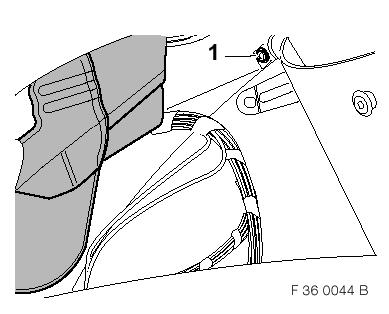
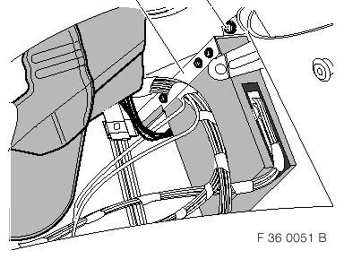
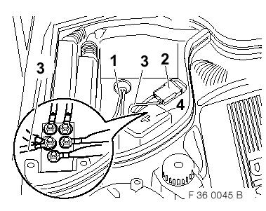
4 3. Installing Amplifier and Routing Adapter Lead F B Place amplifier support bracket (1) on amplifier (2) and firmly secure to amplifier (2) with five fillister head self-tapping screws (3) 3.5x9.5. bensure opening (4) for plug connector is in correct position.c F B Connect adapter lead (1) to amplifier as follows: Connect 25-pin plug connector (2) of adapter lead to plug-in strip (3). Using large screwdriver (4), press plug connector (2) in direction indicated by arrow until it can be heard to lock into the amplifier casing. F B Figure shows installation area at right of centre console. Unscrew hexagon screw (1). Loosen brace (2) and turn down. Hexagon screw (1) is to be re-used. F B Figure shows installation area behind centre console as viewed from driver's footwell. Unscrew recessed cross head screw (1), no longer required. Screw hole to be used later to secure amplifier. F B Figure shows installation area at right of centre console. afor this purpose the side sections of the centre console must be carefully bent towards the outside, risk of breakage! Carefully slide amplifier (1) with preassembled adapter lead from right to left behind centre console. Make sure not to damage connection cable for heating/air conditioning operating unit, cables must be routed under chafe guard (2) of amplifier support bracket (3). Route adapter lead into driver's footwell. ano cables or lines must be fitted on the top side of the amplifier (danger of being trapped when sliding radio into position). F B Fit supplied fillister head self-tapping screw (1) 4.2x19 through amplifier support bracket (2) and firmly secure in hole in centre console. F B Connect 17-pin socket housing (1) from radio wiring harness to 17-pin pin housing (2) of adapter lead (3). If necessary, plug connecting line from CD changer into 17-pin socket housing (4) of adapter lead (3). Connect 17-pin socket housing (4) of adapter lead (3) to radio. Secure adapter lead (3) with cable ties to main wiring harness. 4. Routing Power Lead and Speaker Cables Tie back fitted, original speaker cable, no longer used. Route ground lead, brown wire, with 6 mm cable eye and speaker cable, yellow/black and yellow/brown wire of adapter lead over steering column along main wiring harness to left-hand A-pillar and secure with cable ties. F B Screw ground cable (1), brown wire, with 6 mm cable eye to ground terminal point X9633. Route speaker cable (2), yellow/black and yellow/brown wire, to place of installation of speaker in left-hand A-pillar. aground cable must be firmly secured at existing ground terminal point (poor ground contact will impair operation). The ground cable must not be lengthened for safety reasons. F B Route power lead (1), red wire, and speaker cable (2), blue/black and blue/brown wire, of adapter lead along main wiring harness to right-hand A-pillar and secure with cable ties. Route power lead (1), red wire, through rubber grommet (3) in bulkhead into engine compartment. For this purpose, the rubber grommet (3) must be carefully punctured in the upper area with a marking tool. Seal power lead (1) in rubber grommet (3) with silicone. Route speaker cable (2), blue/black and blue/brown wire, to place of installation of speaker in right-hand A-pillar. F B Fold brace (1) over amplifier support bracket (2) and firmly secure with existing hexagon screw (3). 12
5 4.1 Connecting Power Lead Vehicles with Battery in Engine Compartment F B Cut power lead (1) to size. Crimp on socket contact and plug into fuse holder (2) of power cable (3). Connect power cable (3) to positive terminal of battery. Secure fuse holder (2) of power cable (3) on vehicle wiring harness with cable tie. Secure power lead (1) and power cable (3) with cable tie. 4.2 Connecting Power Lead Vehicles with Battery in Luggage Compartment F B Cut power lead (1) to size. Crimp on socket contact and plug into fuse holder (2) of power cable (3). Screw power cable (3) to power distributor of external jump start terminal point (4). Secure fuse holder (2) of power cable (3) on vehicle wiring harness with cable tie. Secure power lead (1) and power cable (3) with cable tie. 5. Installing Woofers/Mid- Range Speakers in Footwell F B binstallation is shown on the left-hand side of the vehicle. The same procedure should be followed on the right-hand side of the vehicle.c Fit insulation (1) for sealing A-pillar in speaker aperture (2) in left and right A-pillar such that the cavity of the A-pillar is perfectly sealed at the top (in U-form). atake particular care to ensure that cable guide (3) is also sealed off. F B Tie back fitted, original speaker cable, no longer used. Installation on left: Connect speaker cable (1), yellow/black and yellow/brown wire, of adapter lead to supplied woofer/mid-range speaker (2). F B Fit woofer/mid-range speaker (1) in position and firmly secure with the four fillister self-tapping screws (2) provided. F B Carefully adhere seal (1) onto woofer/mid-range speaker (2), making sure seal (1) does not make contact with the diaphragm of the woofer/midrange speaker (2) and a satisfactory seal is ensured. F B bremove insulating mat from A-pillar trim panel and re-adhere after reworking.c Grind flat protruding circular web (1) at rear of speaker grille on both A-pillar trim panels (2) with angle grinder. Remove grinding burrs with file. atake particular care when installing the A-pillar trim panel to ensure that the seal and speaker diaphragm do not make contact and are not damaged. 6. Installing Door Speakers F B binstallation is shown on the left-hand side of the vehicle. The same procedure should be followed on the right-hand side of the vehicle.c Fit tweeter (1) in speaker opening of door trim panel (2) and secure with existing self-tapping screws (3). Connect socket (4) on previously disconnected line of vehicle wiring harness and reinstall door trim panel. 7. General Information Reassemble vehicle in the reverse order of removal. Reconnect battery. Print out fault memory. Carry out function check. Installation on right: Connect speaker cable (1), blue/black and blue/brown wire, of adapter lead to supplied woofer/mid-range speaker (2). 13
6 8. Encoding This system does not require encoding. 9. Function Start up and operation are described in the enclosed customer information/operating instructions for radio and sound module systems. Note that the fader control on the radio has assumed a new function with the sound module system. It is now possible to individually adjust the sound balance between treble and bass with the fader buttons. Forward fader setting corresponds to treble boost. Rear fader setting corresponds to bass boost. 14
7
8

9

10
11
Parts and Accessories Installation Instructions
 Parts and Accessories Installation Instructions Installation kit, sound module MINI (R5) Cooper S (R53) Left-hand drive (LHD) Not suitable for vehicles with option SA 69 (navigation system with on-board
Teile und Zubehör - Einbauanleitung
 Teile und Zubehör - Einbauanleitung ;;;;;; ;;;;;;;; ;;;;;;;; ;;;;;;;;; ;; ;;;;;; ;;;;;;;; ;;;;;;;;; ;;;;;;;;; ;;;;;;;;;; F 39 66 017 für BMW 5er-Reihe, touring (E39/2) Nur zum Gebrauch in der BMW HO bestimmt.
Teile und Zubehör - Einbauanleitung
 Teile und Zubehör - Einbauanleitung F 36 54 051 Überroll-Schutzsystem für BMW Z3 roadster (E36/7) mit Subwoofer - System Harman Kardon Nicht in Kombination mit starrem/klappbarem Windschutz verbaubar.
Teile und Zubehör - Einbauanleitung
 Teile und Zubehör - Einbauanleitung F 46 0033 2W Diebstahlwarnanlage (DWA) für BMW 3er-Reihe (E 46/2/4) Linkslenker mit Funkfernbedienung ab Band (Nur zum Gebrauch in der BMW HO bestimmt.) Einbauzeit ca.
Teile und Zubehör - Einbauanleitung
 Teile und Zubehör - Einbauanleitung F 9 52 000 M Sitzheizung vorne, BMW 5er Reihe (E9) ab 9/98 Fachkenntnisse sind Voraussetzung. BMW Parts and Accessories Installation Instruction Seat heater, front,
Teile und Zubehör - Einbauanleitung
 Teile und Zubehör - Einbauanleitung F 39 0001 2W Standheizung BMW 5er-Reihe (E 39) Linkslenker mit M57 Motor (Diesel) Fachkenntnisse sind Voraussetzung. Einbauzeit ca. 3 (touring 3,5) Stunden, die je nach
Teile und Zubehör - Einbauanleitung
 Teile und Zubehör - Einbauanleitung F 9 09 EVA Park Distance Control (PDC) vorn und hinten BMW 5er-Reihe (E 9) Nur zum Gebrauch in der BMW HO bestimmt. Einbauzeit ca. 8 Stunden, die je nach Zustand und
Teile und Zubehör - Einbauanleitung
 Teile und Zubehör - Einbauanleitung F 46 0350 2W Nachrüstkabelbaum BMW Mobiltelefon (GSM) BMW 3er-Reihe Coupé, touring und Limousine (E46/2/3/4) Die Einbauanleitung ist nur gültig für Fahrzeuge ohne (SA
Teile und Zubehör - Einbauanleitung
 Teile und Zubehör - Einbauanleitung F 36 82 1040 Windschutz klappbare Ausführung Nicht in Kombination mit Überroll-Schutzsystem verbaubar. BMW Z3 roadster (E36/7) Der Einbau des Windschutzes sollte von
Teile und Zubehör - Einbauanleitung
 Teile und Zubehör - Einbauanleitung Heckstützen für den BMW Multi-Trailer BMW Parts and Accessories Installation Instruction Rear supports for the BMW Multi-Trailer Instructions de montage des pièces et
Teile und Zubehör - Einbauanleitung
 Teile und Zubehör - Einbauanleitung 0 0 0 I - TONE + RDS TP TAPE MS BMW 1 2 3 4 5 6 AM FM AUTO _ + A-TEMP C/ F UHR MEMO SET h/dat min/dat HAUPTMENÜ ZIELEINGABE ZIELFÜHRUNG STAND-BY EINSTELLUNGEN ASC R
BMW Parts and Accessories Installation Instructions
 BMW Parts and Accessories Installation Instructions 46 77 B BMW subwoofer module retrofit kit BMW 3 Series compact (E 46/5) LHD Technical and electrical knowledge required Installation time approx. 1.5-2.5
Parts and Accessories Installation Instructions
 Parts and Accessories Installation Instructions R 1 3 5 2 4 F 38 0213 B Basic retrofit kit for hands-free facility for upgrading various mobile phones BMW 7 Series (E38) LHD without telephone preparation
BMW Parts and Accessories Installation Instructions
 1 4 BMW Parts and Accessories Installation Instructions INFO 2 5 3 6 TONE SELET FM AM MODE MENU F 38 0393 B Retrofit Kit Onboard Monitor and Navigation System BMW 7 Series (E38) The installation instructions
Teile und Zubehör - Einbauanleitung
 Teile und Zubehör - inbauanleitung s2 s2 Original MW Zubehör-Seitenschweller MW 3er-Reihe Limousine ( 46/4) achkenntnisse sind Voraussetzung. MW Parts and ccessories Installation Instruction Original MW
Teile und Zubehör Einbauanleitung
 Teile und Zubehör Einbauanleitung Nachrüstung Scheinwerfer Facelift für BMW 5er-Reihe Limousine, touring (E 39, E 39/) bis 9/00 Retrofit Headlights Facelift for BMW 5 Series saloon, touring (E39, E39/)
Original BMW Accessories. Installation Instructions.
 Questo file è stato scaricato da www.bmwretrofit.it @: info@bmwretrofit.it Postmontaggi - codifiche - ricambi - a Cesena Original BMW Accessories. Installation Instructions. TV function retrofit, only
Teile und Zubehör - Einbauanleitung
 Teile und Zubehör - Einbauanleitung BMW Nachrüstsatz BMW Spracheingabesystem seriengleiche Nachrüstung BMW 3er-Reihe Coupé und Limousine (E46/2/4) Nur für Fahrzeuge mit SA 640 und Spracheingabetaste am
Teile und Zubehör - Einbauanleitung
 Teile und Zubehör - Einbauanleitung F 38 0027 EVA BMW Parts and Accessories Installation Instruction Park Distance Control (PDC), rear BMW 7 Series (E38) Best.-Nr. 01 29 0 000 791 XII/98 Printed in Germany
Teile und Zubehör - Einbauanleitung
 Teile und Zubehör - inbauanleitung s2 M MT 2532 Original MW Zubehör-Heckschürze MW 3er-Reihe Limousine ( 46/4) Fachkenntnisse sind Voraussetzung. MW Parts and ccessories Installation Instruction Original
900 Installation instructions. SCdefault
 SCdefault 900 Installation instructions SITdefault Parking assistance (SPA) MONTERINGSANVISNING INSTALLATION INSTRUCTIONS MONTAGEANLEITUNG INSTRUCTIONS DE MONTAGE Accessories Part No. Group Date Instruction
Parts and AccessoriesInstallation Instructions
 MOTOROLA Parts and AccessoriesInstallation Instructions 36 9 Z Retrofit hands-free kit for Motorola mobile phones Series V5 / V369 / V3688 BMW Z3 (E 36/7) roadster and coupé The installation time is approx.
Parts and Accessories Installation Instructions
 7 Parts and Accessories Installation Instructions 3 4 5 6 8 MINI R5 84 Z On-board computer retrofit kit MINI (R 5) The installation time is approx. hours, but this may vary depending on the condition of
Parts and Accessories Installation Instructions
 Parts and Accessories Installation Instructions F 53 7 W Retrofit auxiliary heating system BMW X5 (E 53) with M57 engine (diesel) The installation time is approx..5-4.5 hours (see important information),
CONTENTS TOOLS REQUIRED:
 CONTENTS 1EA. FIVE CHANNEL AMPLIFIER P/N MPDSP033AA 1EA. AMPLIFIER BRACKET P/N RM11JK41 1EA. POWER HARNESS P/N RH41JKP 1EA. OVERLAY HARNESS P/N RH41JK 1EA. FUSE 30 AMP P/N RFUSE30 6EA. WIRE TIE P/N RFZIP6
Parts and Accessories Installation Instructions
 SHIFT DEL Parts and Accessories Installation Instructions MENU 1 2 3 ABC DEF GHI PQRS 5 JKL 5 TUV 6 MNO 6 WXY 6 73 B Electronic Logbook BMW 3 Series Saloon (E 6/) LHD BMW 3 Series Touring (E 6/3) LHD BMW
SWRA211. T-TAP x2 10MM BOLT FUSE WIRE TIES x6 SUBWOOFER ASSEMBLY 200 WATT AMP BRACKET ASSEMBLY POWER HARNESS OVERLAY HARNESS.
 SWRA211 Designed for 2011-2014 Jeep Wrangler two door with base audio or premium audio T-TAP x2 10MM BOLT FUSE WIRE TIES x6 SUBWOOFER ASSEMBLY 200 WATT AMP BRACKET ASSEMBLY POWER HARNESS 2012 Stillwater
Teile und Zubehör - Einbauanleitung
 Teile und Zubehör - Einbauanleitung F 46 84 029 B Autotelefoneinbau (D-Netz) Handy in Mittelkonsole mit Freisprecheinrichtung für BMW 3er Reihe Limousine (E46/4) ohne Telefonvorbereitung Nur zum Gebrauch
Parts and Accessories Installation Instructions
 Parts and Accessories Installation Instructions F 46 3 EVA Headlight Cleaning System (SRA) BMW 3 Series (E 46) The installation time is approx. 3.5 hours, but this may vary depending on the condition of
Parts and Accessories. Installation Instructions.
 Parts and Accessories. Installation Instructions. Park Distance Control (PDC) retrofit kit BMW X5 (E 5) Retrofit kit No. 66 0 0 007 0 66 0 0 4 68 66 0 0 09 685 66 0 0 9 509 Installation time The installation
PWRA215. Designed for 2015 and newer Jeep Wrangler two door with base audio. T-TAP x2 10MM BOLT FUSE WIRE TIES x6 SUBWOOFER ASSEMBLY
 PWRA215 Designed for 2015 and newer Jeep Wrangler two door with base audio T-TAP x2 10MM BOLT FUSE WIRE TIES x6 SUBWOOFER ASSEMBLY 200 WATT AMP BRACKET ASSEMBLY POWER HARNESS 2015 Stillwater Designs PWRA215
Parts and Accessories Installation Instructions
 Parts and Accessories Installation Instructions 46 292 Z Facelift tail lights retrofit kit BMW 3 Series Saloon (E46/4) LHD and RHD Models up to 9/2 Installation time: approx. 2.5 hours The installation
Installation Manual W463 Trailer Hitch Receiver
 Installation Manual W463 Trailer Hitch Receiver For Mercedes-Benz USA Geländewagen W463 from 1990 to 2009 For Mercedes-Benz ROW Geländewagen W463 from 1990 up to 2013 Parts Lists W463 Trailer Hitch Receiver
CVO - with ipod Amp & Speaker Upgrade Install Instructions for Batwing Fairing
 CVO - with ipod Amp & Speaker Upgrade Install Instructions for Batwing Fairing Tools Needed: 1/2 inch Socket Wire Cutters 7/16 inch Socket Wire Strippers 5/16 inch Socket Phillips Screwdriver 1/2 inch
Original BMW Accessories. Installation Instructions.
 Original BMW Accessories. Installation Instructions. Park Distance Control (PDC) Retrofit Kit BMW 3 Series Coupé (E 9) BMW 3 Series Convertible (E 93) These installation instructions are not valid for
SCdefault. 900 Installation instructions
 SCdefault 900 Installation instructions SITdefault Airbag replacement harness MONTERINGSANVISNING INSTALLATION INSTRUCTIONS MONTAGEANLEITUNG INSTRUCTIONS DE MONTAGE Accessories Part No. Group Date Instruction
Amp & Speaker Upgrade Install Instructions for Road Glide
 Amp & Speaker Upgrade Install Instructions for Road Glide Tools Needed: 1/2 inch Socket Wire Cutters 7/16 inch Socket Wire Strippers 10 mm Socket Phillips Screwdriver 1/2 inch Ratchet Wrench T25 Torx driver
Installation instructions, accessories RTI S80
 Installation instructions, accessories Instruction No 8685714 Version 1.0 5 Part. No. RTI S80 Volvo Car Corporation RTI S80-8685714 - V1.0 Page 1 / 25 Equipment A0000161 A0000162 A0801178 D8802049 Page
Parts and Accessories. Installation Instructions.
 Retrofit CD Changer BMW 5 Series (E 60) Parts and Accessories. Installation Instructions. Retrofit kit No.: 65 12 0 301 305 65 12 0 302 342 Installation time The installation time is approx 1.75 hours
Teile und Zubehör - Einbauanleitung
 Teile und Zubehör - Einbauanleitung F 8 0007 EVA BMW Parts and Accessories Installation Instruction Park Distance Control (PDC), front and rear BMW 7 Series (E8) Best.-Nr. 09 0 000 79 II/99 Printed in
BMW Parts and Accessories Installation Instructions
 BMW Parts and Accessories Installation Instructions 6 Z Automatic air conditioning system BMW Series Compact (E 6/5) LHD and RHD with N engine Specialist knowledge required. Only for use in the BMW dealer
2006 MINI Cooper ACCESSORIES & EQUIPMENT Audio, Navigation & Anti-Theft Systems - Repair Instructions - Cooper (1.6L) R50/W10 & Cooper S
 R50/W10 & Cooper S") Fig. 1: Locating Radio Receiver Retaining Screws 2006 MINI Cooper 2002-05 ACCESSORIES & EQUIPMENT Audio, Navigation & Anti-Theft Systems - Repair Instructions - Cooper (1.6L) R50/W10 & Cooper S MONO RADIO
Fig. 1: Locating Radio Receiver Retaining Screws 2006 MINI Cooper 2002-05 ACCESSORIES & EQUIPMENT Audio, Navigation & Anti-Theft Systems - Repair Instructions - Cooper (1.6L) R50/W10 & Cooper S MONO RADIO
INSTALLATION INSTRUCTIONS
 INSTALLATION INSTRUCTIONS Accessory Application Publications No. SYSTEM 2005 ACCORD All 27511 (DX, LX) 2-AND 4-DOOR Issue Date AUG 2004 PARTS LIST Security System Attachment (LX): P/N 08E55-SDA-100A Unit
Amp & Speaker Upgrade Install Instructions for Victory Cross Country
 Amp & Speaker Upgrade Install Instructions for Victory Cross Country Tools Needed: 13mm Socket 4mm Ball Head Allen Socket 5mm Allen Wrench 10mm Wrench Wire Cutters Wire Strippers Phillips Screwdriver Pocket
GENUINE PARTS INSTALLATION INSTRUCTIONS
 GENUINE PARTS INSTALLATION INSTRUCTIONS 1. 2. 3. 4. DESCRIPTION: Accent light Kit APPLICATION: Infiniti JX (2013) PART NUMBER: 999F3 YY000 - Universal Accent Lighting Kit. KIT CONTENTS: Item QTY Description
TOOLS REQUIRED: Panel Removal Tool Phillips Screwdriver 10mm Nut Driver Ratchet 10mm Socket 7mm Wrench 7mm Nut Driver Straight Screwdriver
 CONTENTS: 1EA. FIVE CHANNEL AMPLIFIER/BRACKET ASSEMBLY P/N MPDSP039AA 1EA. OVERLAY HARNESS P/N RH41LX10 3EA. 7MM SCREWS P/N RF7MM 6EA. WIRE TIE P/N RFZIP6 1EA. 30 AMP FUSE P/N RFUSE30 1EA. INSTRUCTIONS
Original BMW Accessories. Installation Instructions.
 Original BMW Accessories. Installation Instructions. Bi-xenon light with ALC BMW Series (E 8, E 82, E 87 LCI) These installation instructions are valid only for cars with SA 502 (headlight washer system)
Parts and Accessories. Installation instructions.
 Parts and Accessories. Installation instructions. Retrofit Kit - Bi-Xenon Headlight BMW 5 Series Saloon (E 60) Installation instructions valid only for vehicles with SA 502 (headlight washer system) and
Original BMW Accessories. Installation Instructions.
 Original BMW ccessories. Installation Instructions. Trailer tow hitch retrofit (removable version) BMW X5 (E70) BMW X6 (E7) Retrofit kit No. 7 60 2 55 44 Electrical components retrofit kit (for E70 only)
BMW Parts and Accessories Installation Instructions
 BMW Parts and Accessories Installation Instructions F 53 039 EVA Additional headlights on roof BMW X5 (E 53) Installation time approx. 4 hours. Installation time can vary according to the condition and
Amp & Speaker Upgrade Install Instructions for Batwing Fairing
 Amp & Speaker Upgrade Install Instructions for Batwing Fairing Tools Needed: 1/2 inch Socket Wire Cutters 7/16 inch Socket Wire Strippers 10 mm Socket Phillips Screwdriver 1/2 inch Ratchet Wrench T25 Torx
CONTENTS TOOLS REQUIRED: *Ratchet*13mm Socket*10mm Socket*Phillips Screwdriver*Pliers*Panel Removal Tool. Subwoofer Installation
 CONTENTS 1EA. SUBWOOFER ASSEMBLY P/N 77KICK40SUBASSEMBLY 1EA. 200 WATT AMP P/N RE08BTL2000R 1EA. POWER HARNESS P/N RHWRANGLERPWR 1EA. OVERLAY HARNESS P/N RHWRANGLER 2EA. T-TAP P/N RFTTAPB 1EA. FUSE 30
Parts and Accessories Installation Instructions
 Parts and Accessories Installation Instructions Active cruise control retrofit (ACC) BMW 7 Series (E 65, E 66) LHD Important information The retrofit kit is for use within the BMW dealership organisation
TOYOTA TACOMA XM SATELLITE RADIO Preparation
 Preparation Part Number: Mounting Kit PT546-35090 Tuner Assembly 8680-0W03 NOTE: Part number of this accessory may not be the same as the part number shown. Tuner Assembly Kit Contents (8680-0W03) Item
CONTENTS: TOOLS REQUIRED:
 CONTENTS: 1EA. FIVE CHANNEL AMPLIFIER/BRACKET ASSEMBLY P/N RBI77KICK37 1EA. POWER HARNESS P/N RH41PMP 1EA. OVERLAY HARNESS P/N RH41PM 3EA. NUT P/N RFM6NUT 6EA. WIRE TIE P/N RFZIP6 1EA. FUSE 30 AMP P/N
INSTALLATION INSTRUCTIONS
 INSTALLATION INSTRUCTIONS Accessory Application Publications No. SYSTEM S2000 AII 26324 Issue Date OCT 2004 PARTS LIST Headrest Speaker System P/N 08A54-S2A-100 3 Small wire ties 2 Headrest speakers 9
GENUINE PARTS INSTALLATION INSTRUCTIONS
 GENUINE PARTS INSTALLATION INSTRUCTIONS 1. 2. 3. 4. DESCRIPTION: Security Light Kit APPLICATION: Altima Coupe and Sedan (2011+) PART NUMBER: 999F4 AX008 - Universal Security Lighting Kit. KIT CONTENTS:
Saab 900 M94-98, Saab 9-3, Saab 9000, Saab 9-5
 SCdefault 900 Monteringsanvisning SITdefault MONTERINGSANVISNING INSTALLATION INSTRUCTIONS MONTAGEANLEITUNG INSTALLATIONS DE MONTAGE Branch cable set LHD Accessories Part No. Group Date Instruction Part
Parts and Accessories Installation Instructions
 Parts and Accessories Installation Instructions 46 856 B Retrofit Kit BMW M Aerodynamics Package BMW 3 Series saloon (E46/4) BMW 3 Series touring (E46/3) Specialist knowledge required. The installation
Original BMW Accessory. Installation Instructions.
 Original MW ccessory. Installation Instructions. Xenon light retrofit with automatic headlight adjustment control MW 3 Series Saloon (E 90) MW 3 Series Touring (E 9) Retrofit kit No. 63 3 0 395 396 63
TOYOTA HIGHLANDE R REARSIGHT Part Number: Code: MC90 KIT CONTENTS ADDITIONAL ITEMS REQUIRED FOR INSTALL RECOMMENDED TOOLS
 TOYOTA HIGHLANDE R 2009- REARSIGHT Part Number: 00016-00085 Code: MC90 KIT CONTENTS ITEM QTY DESCRIPTION 1 1 MIRROR/MONITOR 2 1 REAR CAMERA ASSEMBLY 3 1 CAMERA EXTENSION HARNESS 4 1 SACK PARTS 5 1 OWNER
Saab 9-5 D223L. 900 Installation instructions MONTERINGSANVISNING INSTALLATION INSTRUCTIONS MONTAGEANLEITUNG INSTRUCTIONS DE MONTAGE.
 SCdefault 900 Installation instructions SITdefault Branch cable set LHD MONTERINGSANVISNING INSTALLATION INSTRUCTIONS MONTAGEANLEITUNG INSTRUCTIONS DE MONTAGE Accessories Part No. Group Date Instruction
INSTALLATION INSTRUCTIONS
 INSTALLATION INSTRUCTIONS Accessory Application Publications No. S 1998 CIVIC 2/3/4-DOOR All 18767 Issue Date SEP 1997 PARTS LIST Fog Light Kit: P/N 08V31-S01-100 Right fog light (marked R ) Fuse label
GENUINE PARTS INSTALLATION INSTRUCTIONS
 GENUINE PARTS INSTALLATION INSTRUCTIONS 1. 2. 3. 4. DESCRIPTION: APPLICATION: PART NUMBER: KIT CONTENTS: Accent light Kit Versa Note 999F3 4Z000 - Accent Lighting Kit. 999Q9 AY000 - Accessory Service Connector
INSTALLATION INSTRUCTIONS
 INSTALLATION INSTRUCTIONS Accessory Application CR-V Publications No. AII 32953-34081 Issue Date NOV 2006 PARTS LIST 2 Corner sensor clips Backup Sensor Attachment Kit P/N 08V67-SWA-100A Back-up sensor
INSTALLATION INSTRUCTIONS
 INSTALLATION INSTRUCTIONS Accessory Application Publications No. SYSTEM ACCORD 2-DOOR (LX/EX L4, LX V6) AII 25749 Issue Date FEB 2004 PARTS LIST Double-sided adhesive tape XM Radio Attachment Kit : P/N
SCdefault. 900 Installation instructions. Accessories Part No. Group Date Instruction Part No. Replaces :40-05 Sep
 SCdefault 900 Installation instructions SITdefault Parking assistance (SPA) MONTERINGSANVISNING INSTALLATION INSTRUCTIONS MONTAGEANLEITUNG INSTRUCTIONS DE MONTAGE Accessories Part No. Group Date Instruction
INSTALLATION INSTRUCTIONS
 9002-6513 Rear Vision System W/ Zoom Aftermarket and Factory 8.4 Touch Screen Display (Factory Display requires Chrysler/Dodge dealer to activate) 2009 2012 RAM (Part B) 2013 Current RAM (Part A) NOTE:
Conflicts. TOYOTA 4Runner REARSIGHT. Part Number: Code: MC90 KIT CONTENTS ADDITIONAL ITEMS REQUIRED FOR INSTALL RECOMMENDED TOOLS
 TOYOTA 4Runner 2010 - REARSIGHT Part Number: 00016-00085 Code: MC90 Conflicts KIT CONTENTS ITEM QTY DESCRIPTION 1 1 MIRROR/MONITOR 2 1 REAR CAMERA ASSEMBLY 3 1 CAMERA EXTENSION HARNESS 4 1 SACK PARTS 5
INSTALLATION INSTRUCTIONS
 INSTALLATION INSTRUCTIONS Accessory Application Publications No. KIT P/N 08E49-S9V-100 2003 PILOT LX AII 23629 Issue Date MAY 2002 PARTS LIST Illustration of the Security System installed on the Vehicle
4 Connecting cable 6 Central mounting screws 7 Bolts 5 Ground line
 AR68.10-P-1000GM Remove/install instrument panel 22.3.07 MODEL 463.243 /244 /245 /246 /247 /248 /249 /250 /254 /270 /271 /303 /309 /322 /323 /332 /333 /340 /341 31 Single-fuse holder for electronic ignition
GENUINE PARTS INSTALLATION INSTRUCTIONS
 GENUINE PARTS INSTALLATION INSTRUCTIONS 1. 2. 3. 4. DESCRIPTION: Accent light Kit APPLICATION: Versa (2012) PART NUMBER: 999F3 AW008 - Universal Accent Lighting Kit. KIT CONTENTS: Item QTY Description
CONTENTS TOOLS REQUIRED: *Ratchet*13mm Socket*10mm Socket*Phillips Screwdriver*Pliers*Panel Removal Tool. Subwoofer Installation
 CONTENTS 1EA. SUBWOOFER ASSEMBLY P/N 77KICK24SUBASSEMBLY 1EA. 200 WATT AMP P/N RE08BTL200R 1EA. POWER HARNESS P/N RHWRANGLERPWR 1EA. OVERLAY HARNESS P/N RHWRANGLER 2EA. T-TAP P/N RFTTAPB 1EA. FUSE 30 AMP
INSTALLATION INSTRUCTIONS
 INSTALLATION INSTRUCTIONS Accessory Application Publications No. All 12035 SYSTEM 2012 RIDGELINE Issue Date NOV 2011 PARTS LIST Security System Attachment Kit: P/N 08E55-SJC-101 Flange bolt Unit bracket
GENUINE PARTS INSTALLATION INSTRUCTIONS
 GENUINE PARTS INSTALLATION INSTRUCTIONS 1. 2. 3. 4. DESCRIPTION: Accent light Kit APPLICATION: R42H (2011) PART NUMBER: 999F3 AW000 - Universal Accent Lighting Kit. KIT CONTENTS: Item QTY Description Service
SCAMA10. Designed for Chevrolet Camaro vehicles. Subwoofer Assembly. Subwoofer Bracket Wire Ties x6 Wire Taps x2 Rubber Bumper
 SCAMA10 Designed for 2010-2015 Chevrolet Camaro vehicles Subwoofer Assembly Subwoofer Harness Subwoofer Bracket Wire Ties x6 Wire Taps x2 Rubber Bumper 2012 Stillwater Designs SCAMA10-A3-20151028 M6 Nut
Toyota Corolla Interior Light Upgrade
 TOYOTA Corolla 2010 INTERIOR LIGHT UPGRADE Toyota Corolla 2012- Interior Light Upgrade Part Part Number #: xxxxx-xxxxxx 00016-0009500095 NOTE: Part number of this accessory may If not printing be the same
Parts and Accessories. Installation Instructions.
 Parts and Accessories. Installation Instructions. Universal charger/hands-free kit retrofit BMW 3 Series Saloon (E 90) These installation instructions are only valid for cars with SA 606 (Business navigation
Installation instructions
 Service Installation instructions Audi A4/A5 (B8 series) 2008 Engine sound system For scope of delivery 8T0.071.901* Audi Genuine Accessories Service Department. Technical Information Service Contents
Original BMW Accessories. Installation Instructions.
 Original BMW Accessories. Installation Instructions. BMW Integrated Navigation. BMW Series (F20, F2) BMW 2 Series (F22, F23, F45, F46) BMW 3 Series (F30, F3, F34, F35) BMW 4 Series (F32, F33, F36) BMW
PCAMA13MY. Designed for Chevrolet Camaro vehicles with MyLink. Subwoofer Assembly. Subwoofer Bracket Wire Ties x6 Rubber Bumper
 PCAMA13MY Designed for 2013-2015 Chevrolet Camaro vehicles with MyLink Subwoofer Assembly Subwoofer Harness Adapter Harness Subwoofer Bracket Wire Ties x6 Rubber Bumper 2012 Stillwater Designs PCAMA13MY-A3-20151028
INSTALLATION INSTRUCTIONS
 Rear Vision System Aftermarket and Factory 5.0, 8.4 and 6.1 MyGig Touch Screen Display (Factory Display requires Chrysler/Dodge dealer to activate) 2009 Current* Dodge Ram (Kit part number 1009-6503) *NOTE:
INSTALLATION INSTRUCTIONS
 INSTALLATION INSTRUCTIONS Accessory Application Publications No. CD CHANGER ATTACHMENT KIT 2005 CIVIC SI AII 27936 Issue Date AUG 2004 PARTS LIST CD Changer Attachment Kit (sold separately): P/N 08B26-S5T-100
Original BMW Accessories. Installation Instructions.
 Original BMW Accessories. Installation Instructions. M Performance Alcantara Steering Wheel II with Race Display Retrofit BMW Series (F0/F) BMW Series (F/F3) BMW 3 Series (F30/F3/F34/F35) BMW 4 Series
Parts and Accessories Installation Instructions
 Parts and Accessories Installation Instructions 5 224 B Installation Kit Headlight Cleaning System Mini (R5/R53) LHD and RHD Installation time approx. 1.5-2 hours, which can vary according to the condition
INSTALLATION INSTRUCTIONS
 INSTALLATION INSTRUCTIONS FUEL SURGE TANK INSTALL KIT Honda S2000 Document# 19-0063 Support: info@radiumauto.com WARNING: DO NOT SMOKE WHILE WORKING ON FUEL SYSTEMS. KEEP SPARKS AND OPEN FLAMES AWAY FROM
INSTALLATION INSTRUCTIONS
 INSTALLATION INSTRUCTIONS FUEL SURGE TANK INSTALLATION KIT 1999-2006 BMW E46 COUPE Document# 19-0056 Support: info@radiumauto.com Note: This kit wasn t designed for a FST-R, but can be accomplished. 1.
Conflicts: Vehicles without a sunroof Vehicles with a single sunroof
 Toyota Sienna (Dual Sunroof) 2011-10.2 Overhead Video Part Number: 00016-00110 00016-00110-17 Fit Kit 00016-00120 00016-00120-17 Fit Kit Accessory Code: ED5 Conflicts: Vehicles without a sunroof Vehicles
Designed for 2005 & newer Ford Mustang (Not compatible with Convertible)
") Designed for 2005 & newer Ford Mustang (Not compatible with Convertible) SMUS05 Subwoofer Enclosure Assembly Power Harness Body Harness Input Adapter Wire Ties x6 M6 Nut 25A Fuse Wire Taps x2 SMUS05 A.2
Designed for 2005 & newer Ford Mustang (Not compatible with Convertible) SMUS05 Subwoofer Enclosure Assembly Power Harness Body Harness Input Adapter Wire Ties x6 M6 Nut 25A Fuse Wire Taps x2 SMUS05 A.2
GENUINE PARTS INSTALLATION INSTRUCTIONS
 GENUINE PARTS INSTALLATION INSTRUCTIONS 1. 2. 3. 4. DESCRIPTION: APPLICATION: PART NUMBER: KIT CONTENTS: Accent light Kit Pathfinder 999F3 XZ000 - Accent Lighting Kit. Item QTY Description Service Part
INSTALLATION INSTRUCTIONS
 INSTALLATION INSTRUCTIONS FUEL SURGE TANK INSTALLATION KIT 1999-2006 BMW E46 COUPE Document# 19-0056 Support: info@radiumauto.com Note: This kit was designed for a standard single pump Radium Engineering
HARNESS KIT F INSTALLATION INSTRUCTIONS. Vehicle: Mazda RX-8 Parts number F CFZ (ipod integration module) C9F4 V6 029 (Harness Kit F)
 C9F4 V6 029 (Harness Kit F)") GENUINE ipod INTEGRATION MODULE HARNESS KIT F INSTALLATION INSTRUCTIONS Vehicle: Mazda RX-8 Parts numberf197 79 CFZ (ipod integration module) C9F4 V6 029 (Harness Kit F) Thank you for purchasing a genuine
GENUINE ipod INTEGRATION MODULE HARNESS KIT F INSTALLATION INSTRUCTIONS Vehicle: Mazda RX-8 Parts numberf197 79 CFZ (ipod integration module) C9F4 V6 029 (Harness Kit F) Thank you for purchasing a genuine
RANGE ROVER SPORT OEM TV RETROFIT GUIDE
 RANGE ROVER SPORT OEM TV RETROFIT GUIDE 2 PARTS LIST 4 LOADSPACE TRIM REMOVAL 5 TUNER INSTALLATION 7 UPPER TRIM REMOVAL 9 AMPLIFIER INSTALLATION D PILLAR 11 HEADLINER REMOVAL 12 AMPLIFIER INSTALLATION
TOYOTA VENZA 2009 TRAILER WIRE HARNESS Procedure
 Part Number: PT791-0T099 Kit Contents Item # Quantity Reqd. Description 1 1 Trailer Wire Harness Module 2 1 4-Flat Harness 3 1 Battery Power Wire Harness 4 1 Mounting Bracket, 4-Flat 5 2 Screw #10-24 6
Installation Instructions
 Installation Instructions Electric wiring kit for towbars / 13-pin / 12 Volt / ISO 11446 For use on: MERCEDES BENZ E-Class W 210 Sedan from 05/95 to 02/02 S 210 T-model (station wagon) from 05/96 C 208
GENUINE PARTS INSTALLATION INSTRUCTIONS
 GENUINE PARTS INSTALLATION INSTRUCTIONS 1. 2. 3. 4. DESCRIPTION: APPLICATION: PART NUMBER: KIT CONTENTS: Security light Kit Maxima 999F4 AX009 - Universal Security Lighting Kit. Item QTY Description Service
INSTALLATION INSTRUCTIONS
 INSTALLATION INSTRUCTIONS Accessory Application Publications No. AII 26320 ATTACHMENT KIT 2004 S2000 Issue Date OCT 2003 PARTS LIST CD Changer Attachment Kit: P/N 08B26-S2A-100A Plain washer Template CD
INSTALLATION INSTRUCTIONS
 INSTALLATION INSTRUCTIONS Accessory Application Publications No. AII 38137-38714 Accessory HandsFreeLink 2008 ODYSSEY Issue Date JAN 2008 PARTS LIST Attachment Kit P/N 08E02-SHJ-100B trim Fuse label Fuse
CERTAIN TRANSIT VEHICLES EQUIPPED WITH A TRAILER MODULE TRAILER MODULE FUSE AND FOOTWELL DRAINAGE HOLE
 PAGE 1 OF 19 CERTAIN 2015-2017 TRANSIT VEHICLES EQUIPPED WITH A TRAILER MODULE TRAILER MODULE FUSE AND FOOTWELL DRAINAGE HOLE OVERVIEW In the affected vehicles, it may be possible for water to pool and
INSTALLATION INSTRUCTIONS TRAILER HITCH MAIN HARNESS KIT
 PART NUMBER: 0000-89-N30 GENUINE ACCESSORIES INSTALLATION INSTRUCTIONS TRAILER HITCH MAIN HARNESS KIT APPLICABLE MODELS: 2016 > CX-9 PACKAGE CONTENTS: INSTALLATION INSTRUCTIONS QTY 1 CABLE TIE MOUNT QTY