Operation and Maintenance Manual Magnetic Drive Sealless Pumps MAXP SERIES
|
|
|
- Clyde Tucker
- 6 years ago
- Views:
Transcription
1 Operation and Maintenance Manual Magnetic Drive Sealless Pumps MAXP SERIES Magnatex Pumps, Inc West 12th Street Houston, TX Toll Free: 866.MAG.PUMP Phone: Fax: MAXP IOM-R3 6/30/17
2 !WARNING! MAG-DRIVE PUMP DO NOT WORK ON THIS PUMP IF YOU ARE WEARING A MEDICAL DEVICE (DEFIBRILLATOR, PACEMAKER, ETC.) PERSONNEL WHO EXPERIENCE INTERFERENCE WITH THEIR MEDICAL DEVICE SHOULD MOVE AWAY FROM THE PUMP AND REFRAIN FROM HANDLING MAGNETIC PUMP COMPONENTS. SEEK IMMEDIATE MEDICAL ATTENTION IF YOU HAVE EXPERIENCED INTERFERENCE WITH YOUR MEDICAL DEVICE. The rare earth permanent magnets in this pump have been manufactured such that the magnetic field is directional toward each half of the magnetic coupling. For this reason, the magnetic field that exists outside of the assembled magnetic coupling is minimal. When the two halves are apart, the magnetic field is exposed, which is why we recommend that personnel wearing medical devices DO NOT HANDLE the magnetic coupling components. When the pump is assembled, the magnetic fields from the magnetic coupling components are not exposed and it is safe for wearers of medical devices to be in the general proximity of the assembled pump, whether the pump is in operation or not. 2
3 TABLE OF CONTENTS SECTION HEADING PAGE Warnings... 2 Operating Instructions... 4 Receipt of Equipment... 4 Storage Procedures... 5 Foundation... 5 Location and Piping... 5 Recommended A/F Bearing Lubricant... 6 Rotation Check and Start-Up... 6 Priming... 7 Lubrication of Pump Process Side Bearings...8 Separate Flush to the Rear Casing... 8 Operations and Maintenance... 9 Maintenance Schedule Torque Check...10 Recommended Fastener Torque Values F Size MAXP Series (Pages 12-18) Section Drawing Parts List...13 Disassembly of Wetted End...14 Disassembly of Dry End Assembly of Dry End Assembly of Wetted End M & S Size MAXP Series (Pages 19-25) Section Drawing Parts List...20 Disassembly of Wetted End Disassembly of Dry End Assembly of Dry End Assembly of Wetted End L Size MAXP Series (Pages 26-33) Section Drawing Parts List...27 Disassembly of Wetted End Disassembly of Dry End Assembly of Dry End Assembly of Wetted End Nozzle Loading Criteria Magnet Torque Table
4 WARNING: WHEN WORKING ON MAGNETICALLY DRIVEN PUMPS Strong magnetic fields may damage watches, credit cards, computers, computer tablets, cell phones and other electronic equipment when these are exposed to the magnetic fields of the exposed magnetic coupling components. People with pacemakers should be cautioned that the strong magnetic field may upset the timing or cause the pacemaker to malfunction. When working on the pumps, be aware that tools or metal parts brought within close proximity to the magnets may suddenly be attracted trapping fingers in the process. OPERATING INSTRUCTIONS MAXP ANSI PUMPS This instruction manual is intended to assist those responsible for the installation, operation and maintenance of MAGNATEX Magnetic Drive Sealless Pumps. We recommend thoroughly reading this manual and reviewing the Hydraulic Institute Standards regarding Horizontal Centrifugal Pump installation before installing and operating your pump. RECEIPT OF EQUIPMENT A. Prior to uncrating, check for physical damage to the pumping system and notify the common carrier IMMEDIATELY if any damage is found. B. Check the nameplate on the pump against receiving and purchase order documents to be sure that the correct size pump and materials of construction have been supplied. If a motor has been supplied, check for correct horsepower, speed, and voltage. C. Check to see if flange protectors are intact. If not, check for foreign objects which may have found their way into the pump casing through the flange openings. D. Check for free rotation of the pump. Remove the coupling guard and rotate the pump using the motor shaft flexible coupling. Only slight resistance should be felt. If the pump has heavy resistance, or if any noise is heard, call your MAGNATEX representative or MAGNATEX PUMPS INC. ( ). 4
5 STORAGE PROCEDURES As shipped, the pumps are suitable for short term storage only, ~3-6 months, and the pump unit should be stored indoors in a protected environment away from weather extremes. If long term storage is necessary before the pump will be put into operation, contact your local representative or MAGNATEX PUMPS, INC. for long term storage recommendations. For maximum protection cover the pump with plastic or some other protective material. Motors should be greased and rotated by hand every three (3) months. Maintain pump nozzle flange covers in place until ready to install the pump. Before start-up, refer to the section titled "Rotation Check and Start-Up" (page 6). PUMP AND MOTOR ALIGNMENT MAXP flexible coupled pumps have been pre-aligned with the customer's motor (where applicable) prior to shipment. Because pumps frequently receive rough treatment during shipment, they can become misaligned. To prevent inadvertent operation of a misaligned pump, the spacer coupling has been removed and packed separately with your shipment. The sleeve will need to be reinstalled and the coupling alignment checked prior to starting the pump. The spacer coupling is not designed to compensate for misalignment. Improper alignment will cause vibration and premature bearing failure. FOUNDATION The foundation should be firm and heavy to reduce vibration and prevent flexing which can result in misalignment. A concrete foundation with a solid baseplate is recommended. Foundation bolts of the correct size should be located by reference to certified drawings if the baseplate is supplied by MAGNATEX. A final alignment check should be made after the baseplate has been grouted and set, and the foundation bolts have been tightened. LOCATION & PIPING A. Locate the pump as close as practical to the source of liquid supply. B. The suction line should be as short and straight as possible and contain a minimum number of elbows. Any elbows should be the large radius type. Elbows and fittings should be no closer than pipe diameters to the pump suction to allow undisturbed flow to the pump impeller. The higher the velocity the greater the distance of straight pipe is needed. C. Generally, suction piping should be one or two sizes larger than the pump suction to keep friction loses to a minimum. This becomes more important as the distance between the pump and the liquid supply increases or similarly if piping fittings/connections are located closer than pipe diameters to the pump's suction; see B above. D. The suction piping should have no high spots where air pockets can collect. All joints in the suction line should be tight to prevent air from entering into the system and creating the possibility of vapor locking. This is especially important when suction pressure is lower than the atmospheric pressure. A compound 5
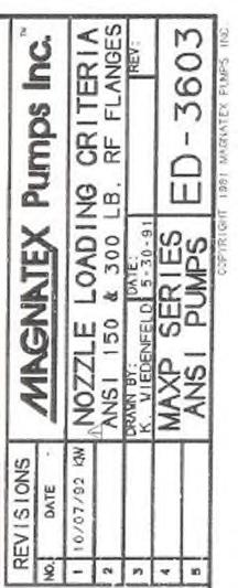
6 pressure gauge should be installed in the suction line as close as possible to the suction flange. E. An air vent should be installed at the initial high point in the pump discharge line. A check valve and shut-off valve should be installed as close as possible to the pump discharge nozzle. The check valve is installed to protect the pump from excessive back pressure, including reverse flow / rotation, and back flow during shut down or driver failure. The discharge valve is located at the pump discharge to regulate flow and isolate the pump for servicing. A pressure gauge should also be installed on the discharge side of the pump as close as possible to the discharge nozzle between the pump and discharge valve. F. Prior to starting the pump it is important to flush the piping to insure the system is free of foreign matter and particles such as pipe scale, welding beads and dirt from system fabrication. Large particles can block the bearing lubrication ports in the pump causing serious damage. In addition, metallic particles can magnetically attach to the inner magnet also resulting in damage. If possible, a temporary startup strainer with a 40x40 US mesh screen should be installed in the pump s suction line. BE VERY CAREFUL not to allow the temporary strainer to be plugged to the point of starving the pump of liquid, resulting in cavitation and the possibility of running the pump dry. Since running the pump dry can destroy the pump s bearings, it is recommended to install a compound pressure gauge between the strainer and pump suction to monitor partial plugging of the strainer. The discharge pressure should also be closely monitored. Any drop in discharge pressure without discharge valve throttling could indicate partial strainer plugging (assuming constant demand to the system). G. Magnatex pumps, although very rugged, are not designed to handle excessive pipe stress. The resulting forces and moments on the pump can result in misalignment and possible damage to the pump. Piping must be anchored as close to, but independent from the pump. Pump and pipe flanges must be positioned together with gaskets (supplied by others) before attempting to tighten flange bolts. See Nozzle Loading Criteria, drawing ED-3603 on Page 34. H. The pump MUST NOT RUN DRY. To assure that adequate liquid is available to the pump suction, a flow sensor and /or power monitor should be installed to shut the pump down in the event of dry run. MAGNATEX provides an optional electronic power monitor offered at time of pump quotation to prevent dry run operation when properly installed and set according to the normal operating parameters of the pump. RECOMMENDED A/F BEARING LUBRICANT, ROTATION CHECK, AND START-UP A. Prior to starting the pump the bearing housing should be filled to the middle of the red dot on the oil gauge (item 90) with high quality turbine oil without additives from a major oil manufacturer of ISO Grade 68 lubrication oil (or equivalent). Synthetic oil of the same viscosity grade may be used if desired. Cooling fluid to the bearing frame taps is recommended for process pumping 6
7 temperature in excess of 350 F to extend service life. During normal operation maintain bearing oil temperature between 125 F and 150 F. B. Removal of air from the pump system is critical for proper system and component performance. Trapped air/vapor voids in the system piping can cause reduced discharge pressure readings and choked system flow. Safely vent all air/vapor from the system following best operational procedures. Before the pump is placed in service check the direction of motor shaft rotation prior to connecting the pump and motor coupling halves with the removable flexible element and spacer flanges. Rotation should match the cast-in arrow or label and the direction of the casing scroll noted under the discharge flange. If the direction of rotation is incorrect, switch two of the three-phase power leads to the motor. If the flexible element is installed and there is liquid in the system, then proceed as follows: A. Open the suction and discharge valve and allow the pump to be filled with liquid.!warning! NEVER RUN THE PUMP DRY B. Remove the coupling guard for visual inspection of motor shaft rotation. B. Bump the motor by quickly pushing the motor start/stop buttons. Rotation should be clockwise as seen from motor end. If the direction of rotation is incorrect, reverse two of the three-phase power leads to the motor. C. After confirming proper rotation open the motor electrical disconnect and install the coupling flexible spacer element. D. Align the pump and motor to within (</=) in all planes. E. Replace the coupling guard. PRIMING A. Open the suction and discharge valves and allow the pump to fill with liquid. If the direction of rotation has not been checked, this must be done as detailed above under Rotation Check and Start-up before proceeding.!warning! NEVER RUN THE PUMP DRY B. Close the discharge valve to 1/4 open. C. Start the motor and immediately check the discharge pressure gauge. The pressure should rise quickly and hold steady. If the pressure rises and then falls back, there is air or vapor in the system. STOP THE PUMP IMMEDIATELY. Wait 15 to 20 seconds before restarting the pump. D. If after repeating Step C several times, the pressure gauge does not hold steady or does not yield the expected pressure (from performance curve), contact your Magnatex representative, or MAGNATEX PUMPS INC. ( ) for assistance. Do not continue to operate the pump under these conditions. 7
8 E. Once the pump is fully primed and the discharge pressure is steady, slowly open the discharge valve until the desired operating point is reached as referenced by discharge pressure reading and /or flow meter indication. The flow and head should match the design performance curve for the pump as ordered. LUBRICATION OF PUMP PROCESS SIDE BEARINGS MAXP pumps have Silicon Carbide (SiC) hydrodynamic bearings on the process side of the pump that are internally lubricated by the pumped liquid. The pump must have liquid in it during operation to avoid damage and breakage of these product lubricated bearings. An optional material of SiC-X is available for enhanced resistance to lubrication and system upset conditions. Contact your Magnatex representative or MAGNATEX PUMPS INC. ( ) for more information. SEPARATE FLUSH TO THE REAR CASING When the pump has been modified for a separate flush, the internal passage lubrication ports are plugged and the separate flush connection must supply liquid to the rear casing prior to starting the pump. OPERATING THE PUMP WITHOUT LIQUID SUPPLY TO THE REAR CASING CAN CAUSE IMMEDIATE SERIOUS DAMAGE. Connect the separate flush piping to the ½ NPT flush connection located 90 to the right on the rear casing flange, as viewed from the pump suction end. A. Allow the rear casing to vent by removing the vent plug or opening the vent valve (if installed) located at the top left side of the rear casing flange, as viewed from the suction end. WARNING - The rear casing vent should be hard piped when handling toxic or hazardous liquids. B. Initiate flow to the rear casing through the separate flush piping. Allow the rear casing to fully vent. Turn the pump shaft by hand to expel any trapped air. C. Close the rear casing vent and maintain separate flush flow to the rear casing. Verify separate flush pressure is adequate by comparing the field reading to the minimum pressure specified by MAGNATEX on Diagram ED-3602 (Page 9). D. After the pressure check is satisfactory, open the suction and discharge valves to prime the pump as outlined in PRIMING (page 7). E. If possible, when the pump is operating, verify the separate flush flow rate is at or above the minimum flow specified by MAGNATEX (Diagram ED-3602). Record pressure readings and flow rates for future reference. To drain the rear casing when using a separate flush, open the vent and remove the drain plug located at the bottom of the rear casing flange. The front casing may be drained through the plug at the bottom of the casing. 8
9 OPERATIONS AND MAINTENANCE A. Operators should make frequent visual inspections to insure the pump is running smoothly without noise or vibration, and that the discharge pressure is holding steady without fluctuation. Any excessive heating of the pump or motor bearings is cause for alarm. The unit should be shut down immediately, an investigation made to determine the cause, and corrective action taken. B. Follow the motor manufacturer's recommendations and keep the motor bearings lubricated properly. WARNING! Never throttle the pump by closing the valve on the suction side of the pump. Throttling the suction side can cause serious damage to the pump. Throttle only from the discharge valve. WARNING! Never operate the pump against a closed discharge valve for more than a few seconds. Low flow operation can cause rapid heating of the pumped liquid with possible vaporization and the pump bearings running dry, resulting in serious damage to the pump. 9
10 MAINTENANCE SCHEDULE Part to be Inspected Inspection Value Frequency Bearing Housing Fill with appropriate oil to the middle Monthly of the sight gauge as needed Change Oil in Bearing Drain old oil and fill with new fresh 3000 Hours Housing oil consider oil analysis program Inner Magnet Dismantle and check Thrust Rings, Every 2 to 3 Years Sub-Assembly Sleeves, and Silicon Carbide Bushings for wear. Use new gaskets and O-rings upon reassembly. Motor As directed in the motor operations As directed in manual motor manual TORQUE CHECK To determine the static breakaway torque of the magnet coupling, place a torque wrench on the impeller nut and hold the outer pump shaft with a wrench. Use an initial torque wrench setting below the minimum torque value listed in the table on Page 1. Slowly turn the torque wrench counter-clockwise (CCW as seen from motor end) until the torque setting is reached or the magnets turn over (decouple). Increase the torque wrench setting repeating in successive trials until the minimum torque value is reached or the magnets decouple. If the magnets decouple before the minimum value is reached, the inner magnet and possibly the outer magnet must be replaced. The preferred method for checking the static torque value when the minimum magnet torque value is less than the impeller nut torque value is to leave the casing attached to the pump, then insert the torque wrench through the suction nozzle and turn the impeller nut in the CW direction (seen from the impeller side of the pump) with the shaft blocked against rotation. An alternate method is to remove the pump from the casing exposing the impeller for securing against rotation and turning the outer pump shaft at the coupling end to accomplish the torque check. In doing so a support should be placed under the frame adapter to brace the pump and the pump feet should be bolted or clamped against movement. GENERAL NOTES A. All inner magnets are marked "FRONT" to assist in correct position for reassembly. This marked end of the magnet must face the impeller of the pump. 10
11 B. All casing covers and rear casings are marked "UP" on outer flange surface and utilize a rocker pin to assist in proper positioning. C. When accomplishing maintenance tasks and during reassembly, all threaded fasteners must be torqued in accordance with the torque table below. RECOMMENDED TORQUE VALUES FOR INTERNAL BOLTS AND SCREWS ALL MAXP SERIES (ANSI) PUMPS MODEL 6 Impeller Nut (ft.lbs.) 11 Impeller Nut Set Screw (in. lbs.) 7 Sleeve Bolt (ft. lbs.) 12 Sleeve Bolt Set Screw (in.lbs.) 8 Hex Socket Head Bolt (in.lbs.) AA6-F AA8-F AB6-F A10-6-S A50-8-S A60-8-S A70-8-S A05-10-S A50-10-S A60-8-M A70-8-M A05-10-M A50-10-M A60-10-M A70-10-M A20-13-M A30-13-M A50-10-L A60-10-L A70-10-L A75-10-L A85-10-L A40-13-L A80-13-L

12 DISASSEMBLY AND REASSEMBLY F SIZE F25, F40, F65, F80 12
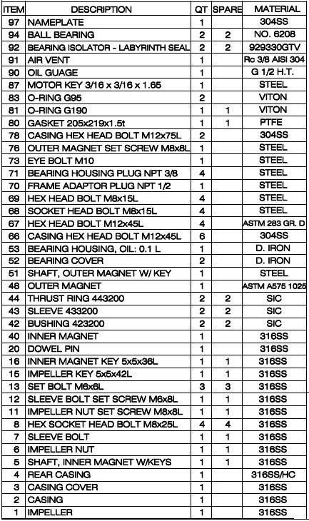
13 13
14 DISASSEMBLY OF WETTED END - F SIZE MAXP SERIES 1. Remove the coupling guard and motor coupling. 2. Remove the casing drain plug (Item 14) and empty the pump of any remaining liquid. If the pump is being operated with a separate flush, remove the rear casing drain plug (Item 18) and rear casing vent (see page 8, SEPARATE FLUSH TO THE REAR CASING) to drain the pump. 3. Remove the 4 hex head bolts (Item 67) which holds the rear casing (Item 4) to the bearing housing. 4. Remove the 8 casing hex head bolts (Items 66 & 78) and the bolts attaching the bearing housing (Item 53) to the baseplate. The pump may now be removed leaving the casing attached to both the baseplate and piping. 5. Set the bearing housing so the motor shaft end is down. Brace the pump by positioning the shaft between supports for direct support to the bearing housing [Fig. 1]. Remove the gasket (Item 80). 6. Loosen the impeller nut set screw (Item 11) and remove the impeller nut (Item 6), the impeller (Item 1), and the impeller key (Item 15). An impact tool may be used for removal (only) of the impeller nut. 7. Place two M16 bolts (spaced at 180 ) into the threaded ears of the bearing housing to jack the rear casing away from the bearing housing [Fig. 2]. Jack evenly to avoid binding between the rear casing and outer magnets. 8. After jacking is complete, pull the rear casing from the bearing housing. During this procedure remember that strong forces are working to keep the inner and outer magnets together. BE CAREFUL TO AVOID TRAPPING YOUR FINGERS BETWEEN THE REAR CASING AND BEARING HOUSING. 9. Remove the 8 hex socket head bolts (Item 8) on the rear casing cover (Item 3). Place the rear casing on its side for horizontal removal of the casing cover [Fig. 3]. 10.Carefully lift off the casing cover (Item 3) as in Figure 3. Both the bushing (Item 42) and the sleeve (Item 43) are now loose and may come out with the casing cover. Since both parts may be damaged if dropped, be prepared to hold them as the casing cover clears the shaft. 14 Figure 1 Figure 2
 that may come out with the assembly. Figure 3 13.")
15 11.Remove the bushing, sleeve, and thrust ring (Item 44). 12.Place the rear casing on its flat bottom and vertically lift out the shaft (Item 5) and inner magnet (Item 40). Be careful of the loose bushing located at the bottom of the rear casing (opposite shaft end) that may come out with the assembly. Figure 3 13.Loosen the sleeve bolt set screw (Item 12) and remove the sleeve bolt (Item 7) [Fig. 4]. Remove the sleeve, the thrust ring, the inner magnet, and the inner magnet key (Item 16). 14.Remove the sleeve bolt by holding the inner magnet with the hand. DO NOT USE CHANNEL LOCKS OR A VISE ON THE INNER MAGNET to avoid damage. Figure 4 DISASSEMBLY OF DRY END - F SIZE MAXP SERIES There are two methods for removing the dry end from the wetted end: shop removal and field removal. Shop removal is outlined on Page 14, DISASSEMBLY OF WETTED END F SIZE MAXP SERIES, procedures 1 through 8. Field removal is outlined below. This procedure is for dry end removal without wet end removal. 1. Remove the coupling guard and motor coupling. 2. Remove the 4 hex head bolts (Item 67) which anchor the bearing housing (Item 53) to the rear casing (Item 4), and the bolts which secure the bearing housing to the baseplate. 3. Place two M16 bolts (spaced at 180 degrees) into the threaded ears of the bearing housing to jack the rear casing away from the bearing housing. Jack evenly to avoid binding between the rear casing and outer magnet. 4. Pull the dry assembly away from the wetted assembly in one swift and steady motion. During this procedure remember that strong forces are working to keep 15
16 the inner and outer magnets together. BE CAREFUL TO AVOID TRAPPING YOUR FINGERS BETWEEN THE REAR CASING AND BEARING HOUSING. 5. When the dry end is separated from the wet end remove the outer magnet set screw (Item 76). 6. Remove the plug located on the right side (centerline) of the bearing housing, as seen from the motor end. 7. Rotate the outer magnet (Item 48) to align the hole in the outer magnet with the bearing housing hole. Place a rod through the bearing housing hole and the outer magnet hole to secure the outer magnet against turning. Turn the outer magnet shaft (Item 51) counter-clockwise from the motor end to unscrew the outer magnet and remove it from the housing. 8. Remove the 4 hex head bolts (Item 69) which secure the bearing cover (Item 52) on the motor side to the bearing housing. Remove the oil seal (Item 92) and the O-ring (Item 83). 9. Remove the 4 socket head bolts (Item 68) which secure the bearing cover on the pump side to the bearing housing. Remove the oil seal (Item 93) and the O-ring (Item 83). 10.Slide the outer magnet shaft (Item 51) and ball bearings (Item 94) out of the bearing housing from the motor end. Press off the two sets of ball bearings from the shaft. ASSEMBLY OF DRY END - F SIZE MAXP SERIES 1. Place a set of ball bearings (Item 94) on each side of the outer magnet shaft (Item 51) and press the bearings to meet the larger radius portion of the shaft. Slide the shaft and bearing assembly into the bearing housing (Item 53) so the keyed end faces the motor. 2. Insert the oil seal (Item 93) and the O-ring (Item 83) into a bearing cover (Item 52) and place it onto the pump side of the magnet shaft. Slide toward the bearing housing and bolt in place with the 4 socket head bolts (Item 68). Insert the oil seal (Item 92) and O-ring (Item 83) into the remaining bearing cover and slide it onto the motor side of the magnet shaft. Bolt in place with the 4 hex head bolts (Item 69). 3. Thread the outer magnet into the outer magnet shaft. To tighten, remove the plug located on the right side (centerline) of the pump, as seen from the motor end. Insert a rod through the hole and through the corresponding hole on the outer magnet. Turn the shaft clockwise (from motor end) to tighten. 4. Secure the outer magnet in place with the outer magnet set screw (Item 76). 5. Thread two M16 bolts into the threaded ears of the bearing housing. Place the O- ring (Item 81) into the bearing housing. 16
17 FIELD ASSEMBLY When the wetted end remains attached to the process piping, the following procedure should be used for assembling the dry end to the wetted end: A. Slide the dry end assembly over the rear casing until the two M16 bolts contact the rear casing flange. During this procedure remember that strong forces are working to pull the inner and outer magnets together. BE CAREFUL TO AVOID TRAPPING YOUR FINGERS BETWEEN THE REAR CASING AND BEARING HOUSING. B. Remove the two M16 bolts evenly to avoid binding between the rear casing and outer magnet. Bolt the bearing housing to the rear casing with the 4 hex head bolts. C. Add oil to the bearing housing through the air vent (Item 91) until the oil is to the center of the oil gauge (Item 90). SHOP ASSEMBLY A. Place the bearing housing in a vertical position with supports under the bearing housing. Do not stand the dry assembly on its outer magnet shaft. B. Lower the rotating assembly into the bearing housing until it rests on the two M16 bolts. Orientate the rotating assembly so the two internal flush holes (behind impeller) are aligned in a vertical position. During this procedure remember that strong forces are working to pull the inner and outer magnets together. BE CAREFUL TO AVOID TRAPPING YOUR FINGERS BETWEEN THE REAR CASING AND BEARING HOUSING. The assembly may be mechanically lowered by removing the impeller nut and threading on a M8 eye bolt. C. Remove the two M16 bolts evenly to avoid binding between the rear casing and outer magnet. Bolt the bearing housing to the rear casing with the 4 hex head bolts. D. Add oil to the bearing housing through the air vent (Item 91) until the oil is to the center of the oil gauge (Item 90). ASSEMBLY OF WETTED END - F SIZE MAXP SERIES 1. Place the inner magnet key (Item 16) onto the inner magnet shaft (Item 5). Slide the inner magnet (Item 40) onto the shaft from the sleeve bolt end (opposite end impeller). The embossed numbers on the magnet's end should face the motor (rear) side of the pump. 2. Slide the thrust ring (Item 44) onto the inner magnet shaft from the sleeve bolt end. The hole in the thrust ring should face the inner magnet and the notch should engage the inner magnet key. 3. Slide a sleeve (Item 43) over the inner magnet shaft and engage the remaining portion of the inner magnet key with the notch on the sleeve end. 17
 into the rear bearing holder and engage the set bolt with the notch on the bottom of the bushing. 6.")
18 4. Thread the sleeve bolt (Item 7) onto the inner magnet shaft. Tighten and secure with the sleeve bolt set screw (Item 12). 5. Thread a set bolt (Item 13) into the rear bearing holder. Carefully slide a bushing (Item 42) into the rear bearing holder and engage the set bolt with the notch on the bottom of the bushing. 6. Thread a set bolt (Item 13) into the shaft flange from the impeller end and tighten. Lift the inner magnet assembly by the shaft and slowly slide it into the rear casing [Fig. 5]. Be careful of the tight tolerances between the rear bushing and sleeve. This should only be done when the outer magnet is removed. 7. Slide a thrust ring onto the shaft so the hole engages the set bolt. Slide a sleeve onto the shaft so the notch is opposite the thrust ring. 8. Place the rear casing on its side for horizontal Figure 5 installation of the casing cover. Align the keyed portion of the inner magnet shaft with the notch in the sleeve. Insert the impeller key (Item 15) onto the shaft and engage the sleeve notch with the rounded end of the key. 9. Insert a set bolt (Item 13) into the front bearing holder on the casing cover (Item 3). Slide the other bushing into the bearing holder and engage the set bolt with the groove in the bushing. 10.Align the two flush holes vertically on the casing cover so the pin located on the VERTICAL POSITION of the rear casing flange engages the hole in the casing cover. Hold the loose bushing while sliding the casing cover over the shaft [Fig. 6]. Be careful of the tight tolerances between the bushing and sleeve. 11.Bolt the casing cover to the rear casing using the 8 hex socket head bolts (Item 8). Tighten evenly to avoid binding. Check for free rotation of the assembly. Figure 6 12.Slide the impeller onto the shaft and thread on the impeller nut. Tighten and secure with the impeller nut set screw (Item 11) (This completes the rotating assembly). 13.Place the gasket (Item 80) onto the rotating assembly and bolt the rotating assembly to the casing (Item 2) with the 8 casing hex head bolts (Items 66 & 78). Tighten the bolts evenly to avoid binding. 14.Make a final inspection by turning the pump shaft and checking for free rotation and listening for noise. If resistance or scraping is felt, or if noises are heard (scraping, etc.), inspect the pump to determine the cause, and take corrective action. 18

19 DISASSEMBLY AND REASSEMBLY M & S SIZE S25, S40, S65, S80 M65, M80, M120 19

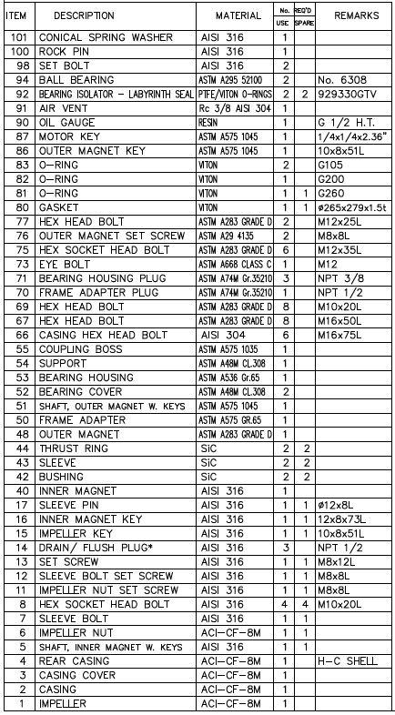
20 * REFER TO DRAWING ED-3602 ON PAGE 9 OF THIS IOM MANUAL 20
21 DISASSEMBLY OF WETTED END M & S SIZE MAXP SERIES 1. Remove the coupling guard and motor coupling. 2. Remove the casing drain plug (Item 14) and empty the pump of any remaining liquid. If the pump is being operated with a separate flush, remove the rear casing drain plug (Item 18) and rear casing vent (see page 4, SEPARATE FLUSH TO THE REAR CASING). 3. Remove the 8 casing hex head bolts (Items 66 & 78) and the bolts attaching the bearing housing (Item 53) to the baseplate. The pump may now be removed leaving the casing attached to both the baseplate and piping. 4. Set the pump so the motor shaft end is down. Brace the assembly by positioning the shaft between supports for direct support to the bearing housing [Fig. 7]. Remove the gasket (Item 80). 5. Loosen the impeller nut set screw (Item 11) and remove the impeller nut (Item 6), the impeller (Item 1), and the impeller key (Item 15). 6. Remove the 4 hex head bolts (Item 67) which holds the frame adapter (Item 50) to the rear casing (Item 4). 7. Place two M20 bolts (spaced at 180 degrees) into the threaded ears of the frame adapter to jack the rear casing away from the frame adapter [Fig. 8]. Jack evenly to avoid binding between the rear casing and outer magnets. 8. After jacking is complete, pull the rear casing from the outer magnet. During this procedure remember that strong forces are working to keep the inner and outer magnets together. It may be helpful to thread a M8 eye bolt into the end of the inner magnet shaft and mechanically lift the rear casing from the outer magnet. BE CAREFUL TO AVOID TRAPPING YOUR FINGERS BETWEEN THE REAR CASING AND BEARING HOUSING. 9. Remove the 8 hex socket head bolts (Item 8) on the rear casing cover (Item 3). Place the rear casing on its side for horizontal removal of the casing cover. Figure 7 Figure 8 21
. Figure 9 Figure 10 12.")
 and remove the sleeve bolt (Item 7) [Fig. 10]. Remove the sleeve, the thrust ring, the inner magnet, and the inner magnet key (Item 16).")
22 10.Carefully slide off the casing cover (Item 3). Both the bushing (Item 42) and the sleeve (Item 43) are now loose and may come out with the casing cover. Since both parts may be damaged if dropped, be prepared to hold them as the casing cover clears the shaft [Fig. 9]. 11.Remove the bushing, sleeve, and thrust ring (Item 44). Figure 9 Figure Place the rear casing on its flat bottom and vertically lift out the shaft (Item 5) and inner magnet (Item 40). Be careful of the loose bushing located at the rear casing support (opposite shaft end). 13.Loosen the sleeve bolt set screw (Item 12) and remove the sleeve bolt (Item 7) [Fig. 10]. Remove the sleeve, the thrust ring, the inner magnet, and the inner magnet key (Item 16). DISASSEMBLY OF DRY END M & S SIZE MAXP SERIES There are two methods for removing the dry end from the wetted end; Shop removal and field removal. For shop removal see page 22, DISASSEMBLY OF WETTED END M&S SIZE MAXP SERIES, procedures 1 through 8. Field removal is outlined below. This procedure is for dry end removal without wet end removal. Remove the coupling guard and motor coupling. 1. Remove the 4 hex head bolts (Item 67) which anchor the frame adapter (Item 50) to the rear casing (Item 4). Remove the bolts which secure the bearing housing (Item 53) to the baseplate. 2. Place two M20 bolts (spaced at 180 degrees) into the threaded ears of the frame adapter to jack the rear casing away from the frame adapter. Jack evenly to avoid binding between the rear casing and outer magnet. 3. Pull the dry assembly away from the wetted assembly. During this procedure remember that strong forces are working to keep the inner and outer magnets together. 4. BE CAREFUL TO AVOID TRAPPING YOUR FINGERS BETWEEN THE REAR CASING AND FRAME ADAPTER. 5. Remove the 4 hex head bolts (Item 67) which attach the frame adapter to the bearing housing. Remove the frame adapter and O-ring (Item 82). 22
23 6. Loosen the two outer magnet set screws (Item 76) and slide off the outer magnet (Item 48). A mechanical pulling device may be helpful in removing the outer magnet. 7. Remove the 4 hex head bolts (Item 69) which secure the bearing cover (Item 52) on the motor end to the bearing housing. Remove the oil seal (Item 92) and the O-ring (Item 83). 8. Remove the 4 hex head bolts which secure the bearing cover on the pump end to the bearing housing. Remove the oil seal (Item 93) and the O-ring. 9. Slide the outer magnet shaft (Item 51) and ball bearings (Item 94) out of the bearing housing from the motor end. Press off the two sets of ball bearings. ASSEMBLY OF DRY END M & S SIZE MAXP SERIES 1. Place a set of ball bearings (Item 94) on each side of the outer magnet shaft (Item 51) and press the bearings to meet the larger radius portion of the shaft. Slide the shaft and bearing assembly into the bearing housing (Item 53) so the smaller keyed end faces the motor. 2. Insert the oil seal (Item 93) and the O-ring (Item 83) into a bearing cover (Item 52) and place it onto the pump side of the magnet shaft. Slide toward the bearing housing and bolt in place with the 4 hex head bolts (Item 69). Insert the oil seal (Item 92) and O-ring (Item 83) into the remaining bearing cover and slide it onto the motor side of the magnet shaft. Bolt in place with the remaining 4 hex head bolts (Item 69). 3. Place the outer magnet key (Item 86) onto the outer magnet shaft and press on the outer magnet (Item 48). Secure the outer magnet with the two outer magnet set screws (Item 76). 4. Place the O-ring (Item 82) onto the frame adapter (Item 50) and slide the frame adapter over the outer magnet. Bolt the frame adapter to the bearing housing with the 4 hex head bolts (Item 67). 5. Bolt the support (Item 54) to the bearing housing. 6. Thread two M20 bolts into the threaded ears of the frame adapter. Place the O- ring (Item 81) onto the frame adapter. FIELD ASSEMBLY When the wetted end remains attached to the process piping, the following procedure should be used for assembling the dry end to the wetted end: A. Slide the dry end assembly over the rear casing until the two M20 bolts contact the rear casing flange. During this procedure remember that strong forces are working to pull the inner and outer magnets together. BE CAREFUL TO AVOID TRAPPING YOUR FINGERS BETWEEN THE REAR CASING AND FRAME ADAPTER. 23
24 B. Remove the two M20 bolts evenly to avoid binding between the rear casing and outer magnet. Bolt the frame adapter to the rear casing with the 4 hex head bolts (Item 67). C. Add oil to the air vent (Item 91) until the oil is to the center of the oil gauge (Item 90). SHOP ASSEMBLY A. Place the frame adapter in a vertical position with supports under the bearing housing. Do not stand the dry assembly on its outer magnet shaft. B. Lower the rotating assembly into the frame adapter until it rests on the two M20 bolts. Orientate the rotating assembly so the two internal flush holes (behind impeller) are aligned in a vertical position. During this procedure remember that strong forces are working to pull the inner and outer magnets together. BE CAREFUL TO AVOID TRAPPING YOUR FINGERS BETWEEN THE REAR CASING AND FRAME ADAPTER. The assembly may be mechanically lowered by removing the impeller nut and threading on a M8 eye bolt. C. Remove the two M20 bolts evenly to avoid binding between the rear casing and outer magnet. Bolt the frame adapter to the rear casing with the 4 hex head bolts (Item 67). D. Add oil through the air vent port (Item 91) until the oil is to the center of the red dot oil gauge (Item 90). ASSEMBLY OF WETTED END M & S SIZE MAXP SERIES 1. Place the inner magnet key (Item 16) onto the inner magnet shaft (Item 5). Slide the inner magnet (Item 40) onto the shaft from the sleeve bolt end (opposite end impeller). The embossed numbers on the magnet's end should face the motor (rear) side of the pump. 2. Slide a thrust ring (Item 44) over the inner magnet shaft from the sleeve bolt end. The hole in the thrust ring should face the inner magnet and the notch should engage the exposed portion of the inner magnet key. 3. Slide a sleeve (Item 43) over the inner magnet shaft and engage the remaining portion of the inner magnet key with the notch on the sleeve end. 4. Thread the sleeve bolt (Item 7) into the inner magnet shaft. Tighten and secure with the sleeve bolt set screw (Item 12). 5. Thread a set bolt (Item 13) into the rear bearing holder. Carefully slide a bushing (Item 42) into the rear bearing holder and engage the set bolt with the notch on the bottom of the bushing. 24
![6. Thread a set bolt (Item 13) into the shaft flange from the impeller end and tighten. Lift the inner magnet assembly by the shaft and slowly slide it into the rear casing [Fig. 11].](/docs-images/77/74983870/images/25-1.jpg "Be careful of the tight tolerances between the rear bushing and sleeve. This should only be done when the outer magnet is removed. 7.")
25 6. Thread a set bolt (Item 13) into the shaft flange from the impeller end and tighten. Lift the inner magnet assembly by the shaft and slowly slide it into the rear casing [Fig. 11]. Be careful of the tight tolerances between the rear bushing and sleeve. This should only be done when the outer magnet is removed. 7. Slide a thrust ring onto the shaft so the hole engages the set bolt. Slide a sleeve onto the shaft so the notch is opposite the thrust ring. 8. Place the rear casing on its side for horizontal installation of the casing cover. Align the keyed portion of the inner magnet shaft with the notch in the sleeve. Insert the impeller key (Item 15) onto the shaft and engage the sleeve notch with the rounded end of the key. Figure 12 Figure Insert a set bolt (Item 13) into the front bearing holder on the casing cover (Item 3). Slide the other bushing into the bearing holder and engage the set bolt with the notch on the bushing end. 10.Align the two flush holes vertically on the casing cover so the pin located on the VERTICAL POSITION of the rear casing flange engages the hole in the casing cover. Hold the loose bushing in place while sliding the casing cover over the shaft. [Fig. 12]. 11.Be careful of the tight tolerances between the bushing and sleeve. 12.Bolt the casing cover to the rear casing using the 8 hex socket head bolts (Item 8). Tighten evenly to avoid binding. Check for free rotation of the assembly 13.Slide the impeller onto the shaft and thread on the impeller nut. Tighten and secure with the impeller nut set screw (Item 11). (This completes the rotating assembly.) 14.Place the gasket (Item 80) onto the rotating assembly and bolt the rotating assembly to the casing (Item 2) with the 8 casing hex head bolts (Items 66 & 78). Tighten the bolts evenly to avoid binding. 15.Make a final inspection by turning the pump shaft and checking for free rotation and listening for noise. If resistance or scraping is felt, or if noises are heard (scraping, etc.), inspect the pump to determine the cause, and take corrective action. 25

26 DISASSEMBLY AND REASSEMBLY L SIZE L80, L120, L160 26
27 27
 and rear casing vent (see page 4, SEPARATE FLUSH TO THE REAR CASING). 3.")

28 DISASSEMBLY OF WETTED END - L SIZE MAXP SERIES 1. Remove the coupling guard and motor coupling. 2. Remove the casing drain plug (Item 14) and empty the pump of any remaining liquid. If the pump is being operated with a separate flush, remove the rear casing drain plug (Item 18) and rear casing vent (see page 4, SEPARATE FLUSH TO THE REAR CASING). 3. Remove the 12 casing hex head bolts (Item 66 & 78) and the bolts attaching the bearing housing (Item 53) to the baseplate. The pump may now be removed leaving the casing attached to both the baseplate and piping. 4. Set the pump so the motor shaft end is down. Brace the assembly by positioning the shaft between supports for direct support to the bearing housing [Fig. 13]. Remove the gasket. 5. Loosen the impeller nut set screw (Item 11) and remove the impeller nut (Item 6), the impeller (Item 1), and the impeller key (Item 15). 6. Remove the 4 hex head bolts (Item 67) which holds the frame adapter (Item 50) to the rear casing (Item 4). Figure Place two M20 bolts (spaced at 180 degrees) into the threaded ears of the frame adapter to jack the rear casing away from the frame adapter [Fig. 14]. Jack evenly to avoid binding between the rear casing and outer magnets. Figure 14 28
![8. Thread a M10 eye bolt into the end of the inner magnet shaft and mechanically lift the rear casing away from the frame adapter [Fig. 15].](/docs-images/77/74983870/images/29-0.jpg "During this procedure remember that strong forces are working to keep the inner and outer magnets together. BE CAREFUL TO AVOID TRAPPING YOUR FINGERS BETWEEN THE REAR CASING AND FRAME ADAPTER. 9.")
 is loose it may come out with the casing cover. Be prepared to hold the sleeve as the casing cover clears the shaft [Fig. 16]. Figure 16 11.")
29 8. Thread a M10 eye bolt into the end of the inner magnet shaft and mechanically lift the rear casing away from the frame adapter [Fig. 15]. During this procedure remember that strong forces are working to keep the inner and outer magnets together. BE CAREFUL TO AVOID TRAPPING YOUR FINGERS BETWEEN THE REAR CASING AND FRAME ADAPTER. 9. Remove the 12 hex socket head bolts on the rear casing cover (Item 3). Place the rear casing on its side for horizontal removal of the casing cover. 10.Carefully slide off the casing cover. Since the sleeve (Item 43) is loose it may come out with the casing cover. Be prepared to hold the sleeve as the casing cover clears the shaft [Fig. 16]. Figure Slide off the sleeve and thrust ring (Item 44). Remove the bushing set bolt (Item 19) and slide out the bushing (Item 42) and thrust washer (Item 22). The sleeve pin (Item 17) may also be removed if being replaced. 12.Place the rear casing on its flat bottom and thread the impeller nut onto the shaft. Carefully lift out the shaft and inner magnet assembly. You may wish to thread a M10 eye bolt into the shaft (instead of impeller nut) and mechanically lift out the shaft and inner magnet assembly. 13.Loosen the sleeve bolt set screw (Item 12) and remove the sleeve bolt (Item 7) [Fig. 23]. Remove the sleeve, the thrust ring, the inner magnet, and the inner magnet key (Item 16). Remove the bushing set bolt (Item 19) and slide out the remaining bushing. 14.Remove the sleeve bolt by holding the inner magnet with the hand [Fig. 17]. DO NOT USE CHANNEL LOCKS OR A VISE ON THE INNER MAGNET. 15.Remove the sleeve bolt by holding the inner magnet with the hand. DO NOT USE CHANNEL LOCKS OR A VISE ON THE INNER MAGNET. Figure 15 Figure 17 29
30 DISASSEMBLY OF DRY END - L SIZE MAXP SERIES There are two methods for removing the dry end from the wetted end: shop removal and field removal: Shop removal is outlined under "DISASSEMBLY OF WETTED END L SIZE MAXP SERIES", procedures 1 through 8. Field removal is outlined below. This procedure is for dry end removal without wet end removal. 1. Remove the coupling guard and motor coupling. 2. Remove the 4 hex head bolts (Item 67) which anchor the frame adapter (Item 50) to the rear casing (Item 4). Remove the bolts which secure the bearing housing (Item 53) to the baseplate. 3. Place two M20 bolts (spaced at 180 degrees) into the threaded ears of the frame adapter to jack the rear casing away from the frame adapter. Jack evenly to avoid binding between the rear casing and outer magnets. 4. Pull the dry assembly away from the wetted assembly. During this procedure remember that strong forces are working to keep the inner and outer magnets together. BE CAREFUL TO AVOID TRAPPING YOUR FINGERS BETWEEN THE REAR CASING AND FRAME ADAPTER. 5. Remove the 4 hex head bolts (Item 67) which attach the frame adapter to the bearing housing. Remove the frame adapter and O-ring (Item 82). 6. Remove the six hex head bolts (Item 75) which secure the outer magnet (Item 48) to the coupling boss (Item 55). Slide off the outer magnet. 7. Loosen the two outer magnet set screws (Item 76) and slide off the coupling boss. A mechanical pulling device may be helpful. Remove the outer magnet key (Item 86). 8. Remove the 4 hex head bolts (Item 69) which secure the bearing cover (Item 52) on the motor end to the bearing housing. Remove the oil seal (Item 92) and the O-ring (Item 83). 9. Remove the 4 hex head bolts which secure the bearing cover on the pump end to the bearing housing. Remove the oil seal (Item 93) and the O-ring. 10.Slide the outer magnet shaft (Item 51) and ball bearings (Item 94) out of the bearing housing from the motor end. Press off the two sets of ball bearings. 30
31 ASSEMBLY OF DRY END - L SIZE MAXP SERIES 1. Place a set of ball bearings (Item 94) on each side of the outer magnet shaft (Item 51) and press the bearings to meet the larger radius portion of the shaft. Slide the shaft and bearing assembly into the bearing housing (Item 53) so the smaller keyed end faces the motor. 2. Insert the oil seal (Item 93) and the O-ring (Item 83) into a bearing cover (Item 52) and place it onto the pump side of the magnet shaft. Slide toward the bearing housing and bolt in place with the 4 hex head bolts (Item 69). 3. Insert the oil seal (Item 92) and O-ring (Item 83) into the remaining bearing cover and slide it onto the motor side of the magnet shaft. Bolt in place with the 4 hex head bolts. 4. Place the outer magnet key (Item 86) onto the outer magnet shaft and press on the coupling boss (Item 55). Secure the coupling boss with the two outer magnet set screws (Item 76). 5. Slide the outer magnet (Item 48) onto the coupling boss. Bolt the outer magnet to the coupling boss with the 6 hex head bolts (Item 75). 6. Place the O-ring (Item 82) onto the frame adapter and slide the frame adapter over the outer magnet. Bolt the frame adapter to the bearing housing with the 4 hex head bolts (Item 67). 7. Bolt the support (Item 54) to the bearing housing. 8. Thread two M20 bolts into the threaded ears of the frame adapter. Place the O- ring (Item 81) onto the frame adapter. FIELD ASSEMBLY When the wetted end remains attached to the process piping the following procedure should be used for assembling the dry end to the wetted end: A. Slide the dry end assembly over the rear casing until the two M20 bolts contact the rear casing flange. During this procedure remember that strong forces are working to pull the inner and outer magnets together. BE CAREFUL TO AVOID TRAPPING YOUR FINGERS BETWEEN THE REAR CASING AND FRAME ADAPTER. B. Remove the two M20 bolts evenly to avoid binding between the rear casing and outer magnet. Bolt the frame adapter to the rear casing with the 4 hex head bolts (Item 67). C. Add oil to the air vent (Item 91) until the oil is to the center of the oil gauge (Item 90). SHOP ASSEMBLY D. Place the frame adapter in a vertical position with supports under the bearing housing. Do not stand the dry assembly on its outer magnet shaft. 31
 are aligned vertically. Be careful of the strong magnetic forces which will pull the two assemblies together. F.")
32 E. Remove the impeller nut and thread an M8 eye bolt into the shaft end. Mechanically lower the rotating assembly (wetted end) into the frame adapter until it rests on the two M20 bolts. Orientate the rotating assembly so the two internal flush holes (behind impeller) are aligned vertically. Be careful of the strong magnetic forces which will pull the two assemblies together. F. Remove the two M20 bolts evenly to avoid binding. Bolt the frame adapter to the rear casing with the 4 hex head bolts (Item 67). G. Add oil to the air vent (Item 91) until the oil is to the center of the oil gauge (Item 90). ASSEMBLY OF WETTED END - L SIZE MAXP SERIES 1. Place the inner magnet key (Item 16) onto the inner magnet shaft (Item 5). Slide the inner magnet (Item 40) onto the shaft from the sleeve bolt end (opposite end impeller). The embossed numbers on the magnet's end should face the motor (rear) side of the pump. 2. Slide a thrust ring (Item 44) over the inner magnet shaft from the sleeve bolt end. The hole in the thrust ring should face the inner magnet and the notch should engage the exposed portion of the inner magnet key. 3. Slide a sleeve over the inner magnet shaft and engage the remaining portion of the inner magnet key with the notch on the sleeve end. 4. Thread the sleeve bolt (Item 7) onto the inner magnet shaft. Tighten and secure with the sleeve bolt set screw (Item 12). 5. Carefully slide a bushing (Item 42) into the rear bearing holder. Align the notch on the bushing side with the hole in the bearing holder. Thread a set bolt (Item 19) into the bearing holder and engage the notch in the bushing. 6. Thread a set bolt (Item 13) into the shaft flange from the impeller end and tighten. Place the sleeve pin (Item 17) onto the shaft. Figure 18 32
![7. Thread on the impeller nut (Item 6). Lift the inner magnet assembly by the impeller nut and slowly slide it into the rear casing [Fig. 19].](/docs-images/77/74983870/images/33-0.jpg "You may wish to thread a M10 eye bolt into the shaft (instead of impeller nut) and mechanically lower the inner magnet assembly into the rear casing.")
33 7. Thread on the impeller nut (Item 6). Lift the inner magnet assembly by the impeller nut and slowly slide it into the rear casing [Fig. 19]. You may wish to thread a M10 eye bolt into the shaft (instead of impeller nut) and mechanically lower the inner magnet assembly into the rear casing. Be careful of the tight tolerances between the rear bushing and sleeve. This should only be done when the outer magnet is removed. 8. Remove the impeller nut (or M10 eye bolt) and slide a thrust ring onto the shaft so the hole engages the set bolt. Slide a sleeve onto the shaft so the notch on the sleeve end engages the sleeve pin. Figure Place the thrust washer (Item 22) into the bearing holder on the casing cover (Item 3) and slide the other bushing into the bearing holder. Align the notch on the bushing side with the hole in the bearing holder. Thread a set bolt (Item 19) into the bearing holder and engage the notch in the bushing. 10.Place the rear casing on its side for horizontal installation of the casing cover. Align the two flush holes vertically on the casing cover so the pin located on the VERTICAL position of the rear casing flange engages the hole in the rear casing cover. Be careful of the tight tolerances between the bushing and sleeve. 11.Bolt the casing cover to the rear casing using the 12 hex socket head bolts (Item 8). Tighten evenly to avoid binding. Check for free rotation of the assembly. 12.Place the impeller key (Item 15) onto the shaft so the flat end of the key faces the impeller nut. Slide the impeller (Item 1) onto the shaft and thread on the impeller nut. Tighten and secure with the impeller nut set screw (Item 11). (This completes the rotating assembly.) 13.Place the gasket (Item 80) onto the rotating assembly and bolt the rotating assembly to the casing (Item 2) with the 12 casing hex head bolts (Items 66 & 78). Tighten the bolts evenly to avoid binding. 14.Make a final inspection by turning the pump shaft by hand and checking for free rotation and listening for noise. If resistance or scraping is felt, or if noises are heard (scraping, etc.), inspect the pump to determine the cause, and take corrective action. 33
34 34
SERIES PC INSTRUCTION AND OPERATION MANUAL
 MEGGA SERIES PC INSTRUCTION AND OPERATION MANUAL Models PCT and PCF Close-coupled and frame-mounted single-stage horizontal end-suction pumps. WARNING: Read this manual before installing or operating this
Service Manual #67. Installation and Service Instructions 6000, 7000 & 8000 Series Magnetically Coupled Pumps
 Service Manual #67 Installation and Service Instructions 6000, 7000 & 8000 Series Magnetically Coupled Pumps Table of Contents Section Description Page 1 General Description 4 2 The Pumping Principle 5
Series Base mounted pump. Installation and operating instructions
 Series 4030 Installation and File No: 40.80 Date: june 25, 2015 Supersedes: 40.80 Date: october 10, 2009 contents General 4 Inspection 4 Installation - Series 4030 base mounted Pump 4 1.0 Location 4 2.0
Fisher 657 Diaphragm Actuator Sizes and 87
 Instruction Manual 657 Actuator (30-70 and 87) Fisher 657 Diaphragm Actuator Sizes 30 70 and 87 Contents Introduction... 1 Scope of Manual... 1 Description... 2 Specifications... 2 Installation... 3 Mounting
PROMAG SR SERIES SEAL-LESS CENTRIFUGAL PUMPS
 PROMAG SR SERIES SEAL-LESS CENTRIFUGAL PUMPS INSTALLATION, OPERATION, AND MAINTENANCE INSTRUCTIONS TO OBTAIN THE BEST PERFORMANCE FROM YOUR PROMAG SR PUMP, PLEASE READ THE MANUAL CAREFULLY. Failure to
Series Base mounted pump. Installation and operating instructions
 Series 4030 Installation and File No: 40.80 Date: december 12, 2016 Supersedes: 40.80 Date: july 27, 2016 contents General 4 Inspection 4 Installation - Series 4030 base mounted Pump 4 1.0 Location 4
KP-C Series. Close Coupled End Suction Centrifugal Pumps. Installation, Operation and Maintenance
 KP-C Series Close Coupled End Suction Centrifugal Pumps Installation, Operation and Maintenance PUMP MODEL NOMENCLATURE KP - 8 x 6 x 16 - E C - AI - BCM Pump Series Suction Pipe Size (in) Discharge Pipe
PROJ. NO SECTION HYDRONIC PUMPS
 SECTION 23 21 23 HYDRONIC PUMPS PART 1 - GENERAL 1.1 RELATED DOCUMENTS A. Drawings and general provisions of the Contract, including General and Supplementary Conditions and Division 01 Specification Sections,
This manual presents installation, servicing, troubleshooting, and maintenance for M PUMPS CM MAG-M SERIES Information that may be required regarding
 Installation, Operating, Maintenance & Safety Instruction for M PUMPS CM MAG-M SERIES Centrifugal light Mag-Drive pumps (CM MAG-M06/1/2/3/4) This manual presents installation, servicing, troubleshooting,
Type 1051 and 1052 Size 33 Diaphragm Rotary Actuator
 Instruction Manual Type 1051 and 1052 Size 33 Diaphragm Rotary Actuator 1051 & 1052 Actuator Contents Introduction............................. 1 Scope of Manual........................... 1 Description................................
ROOTS Meters Series B3 Meter Models 8C175-56M175
 ROOTS Meters Series B3 Meter Models 8C175-56M175 Refer to IOM-B3 for Complete Instructions IS:B3 3.03 RECEIVING, HANDLING AND STORAGE ROOTS rotary positive displacement gas meters are precision measurement
PO Box 645, Stockton, Missouri, FAX superiorgearbox.com
 I000-7000-D0447-A 4/7/05 1 SAFETY PRECAUTIONS CAUTION Please read this entire document prior to operating the gear drive. Gear drive failure and / or injury to operators may be caused by improper installation,
NOTE: Visit our website at for video repair procedures, under the Tools section.
 Repair Instructions Hypro Repair Tools: Tool Box No. 3010-0168 1/4" Allen Wrench No. 3020-0008 Support Bars (2) No. 3010-0064 Port Brush No. 3010-0066 1/16" Allen Wrench No. 3020-0009 Brush Holder No.
K81 Guardian Fire Hydrants. Operation & Maintenance Guide
 Kennedy Valve K81 Guardian Fire Hydrants Operation & Maintenance Guide Installation 1. When hydrants are received from manufacturer they should be handled carefully to avoid breakage and damage to flanges.
NECO Pumping Systems
 INSTALLATION OPERATION & MAINTENANCE INSTRUCTIONS For Your NECO Pumping Systems PACKAGED CIRCULATING SYSTEM THIS COMPLETELY ASSEMBLED, TESTED, PACKAGED CIRCULATING SYSTEM IS OF THE HIGHEST QUALITY AND
CSO / CP PUMPS Vertical Spindle Type Installation, Operation and Maintenance Manual
 CSO / CP PUMPS Vertical Spindle Type Installation, Operation and Maintenance Manual www.sameng.co.za (011) 823 4250 Proud Manufacturers of SAMCO Pumps Contents INTRODUCTION 3 LOCATION OF UNIT 3 INSTALLATION
SERIES FE MAGNETIC COUPLED PUMPS
 SERIES FE MAGNETIC COUPLED PUMPS Refer to Bulletin P-518 O-2804 TABLE OF CONTENTS Description Page Number Important Information...3 Chemical Reaction Disclaimer...3 Safety Precautions...3 Installation/Operation
INSTALLATION, OPERATION AND MAINTENANCE MANUAL (IOM)
") INSTALLATION, OPERATION AND MAINTENANCE MANUAL (IOM) IOM-1088 03-16 Model 1088 Vacu-Gard Blanketing Valve ISO Registered Company SECTION I I. DESCRIPTION AND SCOPE The Model 1088 Vacu-Gard is a tank blanketing
INSTALLATION, OPERATION AND MAINTENANCE MANUAL (IOM) IOM-1088 03-16 Model 1088 Vacu-Gard Blanketing Valve ISO Registered Company SECTION I I. DESCRIPTION AND SCOPE The Model 1088 Vacu-Gard is a tank blanketing
Pressure Relief Valve Maintenance Manual
 Technical Manual 1098T Pressure Relief Valve Maintenance Manual Farris Engineering Division of Curtiss-Wright Flow Control Corporation TABLE OF CONTENTS - Manual Revision 0 Introduction & Safety Tips...
NORTHWESTERN UNIVERSITY PROJECT NAME JOB # ISSUED: 03/29/2017
 SECTION 23 2123 - PUMPS PART 1 - GENERAL 1.1 RELATED DOCUMENTS A. Drawings and general provisions of the Contract, including General and Supplementary Conditions and Division 01 Specification Sections,
1. Wiring Diagrams: Power, signal, and control wiring.
 Page 232123-1 SECTION 232123 - PART 1 - GENERAL 1.1 RELATED DOCUMENTS A. Drawings and general provisions of the Contract, including General and Supplementary Conditions and Division 01 Specification Sections,
Operating & Maintenance Manual For Steam Conditioning Valve
 For Steam Conditioning Valve 1 Table of Contents 1.0 Introduction 3 2.0 Product description 3 3.0 Safety Instruction 4 4.0 Installation and Commissioning 5 5.0 Valve Disassembly 6 6.0 Maintenance 6 7.0
WMTA6 LN SERIES SEAL-LESS MAG-DRIVE MULTI-STAGE TURBINE PUMPS
 WMTA6 LN SERIES SEAL-LESS MAG-DRIVE MULTI-STAGE TURBINE PUMPS INSTALLATION, OPERATION, AND MAINTENANCE INSTRUCTIONS TO OBTAIN THE BEST PERFORMANCE FROM YOUR WARRENDER WMTA6 LN PUMP, PLEASE READ THIS MANUAL
Ideal Installation. I & M Mark 67 (1/2 6 ) Control Line. Installation & Maintenance Instructions for Mark 67 Pressure Regulators
 Control Line. Installation & Maintenance Instructions for Mark 67 Pressure Regulators") I & M Mark (/ ) 0 Wasson Road Cincinnati, OH 0 USA Phone --00 Fax -8-00 info@richardsind.com www.jordanvalve.com Installation & Maintenance Instructions for Mark Pressure Regulators Warning: Jordan Valve
I & M Mark (/ ) 0 Wasson Road Cincinnati, OH 0 USA Phone --00 Fax -8-00 info@richardsind.com www.jordanvalve.com Installation & Maintenance Instructions for Mark Pressure Regulators Warning: Jordan Valve
S3 General Installation
 Wilfley Drylock Assembly General Installation Operating & General Servicing Clearance Settings Safety Precautions Spare Parts Ordering Assembly Instructions Model S3 General Installation Inspection upon
Fisher 2052 Diaphragm Rotary Actuator
 Instruction Manual 2052 Actuator Fisher 2052 Diaphragm Rotary Actuator Contents Introduction... 1 Scope of Manual... 1 Description... 1 Specifications... 4 Installation... 4 Actuator Mounting and Changing
Installation and Maintenance Instructions JSE2-0241MAEAD Extruder Clutch. World Leader in Modular Torque Limiters
 World Leader in Modular Torque Limiters Installation and Maintenance Instructions JSE2-0241MAEAD Extruder Clutch 1304 Twin Oaks Street Wichita Falls, Texas 76302 (940) 723-7800 Fax: (940) 723-7888 E-mail:
PO Box 645, Stockton, Missouri, FAX superiorgearbox.com W D0446-A 4/1/05 1
 W000-7000-D0446-A 4/1/05 1 SAFETY PRECAUTIONS CAUTION Please read this entire document prior to operating the gear drive. Gear drive failure and / or injury to operators may be caused by improper installation,
HYDRAULICS. TX420 & & lower. Hydraulic Tandem Pump Removal. 4. Remove the LH side panel (Fig. 0388).
.") TX420 & 425 240000299 & lower 4. Remove the LH side panel (Fig. 0388). Hydraulic Tandem Pump Removal Note: Cleanliness is a key factor in a successful repair of any hydraulic system. Thoroughly clean all
TX420 & 425 240000299 & lower 4. Remove the LH side panel (Fig. 0388). Hydraulic Tandem Pump Removal Note: Cleanliness is a key factor in a successful repair of any hydraulic system. Thoroughly clean all
COYOTE ENTERPRISES, INC. 9/10 BLAST WHEEL MAINTENANCE & ASSEMBLY MANUAL
 COYOTE ENTERPRISES, INC. 9/10 BLAST WHEEL MAINTENANCE & ASSEMBLY MANUAL Parts & Machinery for the Abrasive Blast Industry 27301 East 121st Street Coweta, Oklahoma 74429 (918) 486-8411 Fax (918) 486-8412
INSTRUCTION MANUAL INTERNAL GEAR PUMP TITAN G-4124A SERIES=> FLANGED TITAN G-124A SERIES => FLANGED MODELS:
 INSTRUCTION MANUAL INTERNAL GEAR PUMP TITAN G-4124A SERIES=> FLANGED TITAN G-124A SERIES => FLANGED MODELS: G-H, G-HL, G-K, G-KK, G-L, G-LQ, G-LL, GLS, G-Q, G-QS 1 Contents Maintenance Thrust bearing adjustment
INSTALLATION INSTRUCTIONS
 INSTALLATION INSTRUCTIONS REAR DISC CONVERSION KIT A128-4 1997-2004 JEEP WRANGLER (TJ) WITH DANA 44 AXLES (non-abs) Thank you for choosing STAINLESS STEEL BRAKES for your braking needs. Pleases take the
END SUCTION CENTRIFUGAL PUMPS
 OWNERS GUIDE TO INSTALLATION AND OPERATION FW000 009 Supersedes 07 END SUCTION CENTRIFUGAL PUMPS READ THESE INSTRUCTIONS CAREFULLY Read these installation instructions in detail before installing your
METERING VALVE 2" STEM GUIDED
 2" STEM GUIDED All Rights Reserved. All contents of this publication including illustrations are believed to be reliable. And while efforts have been made to ensure their accuracy, they are not to be construed
INSTALLATION & MAINTENANCE MANUAL
 INSTALLATION & MAINTENANCE MANUAL 3-WAY/4-WAY/5-WAY MULTI-PORT BALL VALVES T TEFLON PARTS - 1. Seat x 5 pcs. 2. Joint Gasket x 5 pcs. 3. Retainer Seal x 5 pcs. 4. Thrust Washer x 1 pc. 5. O-Ring x 1 pc
5000/6000 SERIES BALL VALVES INSTALLATION - MAINTENANCE MANUAL
 Date: August 2011 / Page 1 of 6 5000/6000 SERIES BALL VALVES INSTALLATION - MAINTENANCE MANUAL DESIGN The design features three piece construction and a free floating ball allowing ease of maintenance
INSTALLATION/OPERATION/MAINTENANCE INSTRUCTIONS FOR ARCHON MODELS WD2010L, WD2010, WD2010H WASHDOWN STATIONS. ARCHON Industries, Inc.
 ARCHON Industries, Inc. Washdown Stations Models WD2010L, WD2010, WD2010H Installation / Operation / Maintenance Instructions 1 This manual has been prepared as an aid and guide for personnel involved
Instructions for Installation, Operation, Care and Maintenance
 Bulletin 407 Rev. T Model E Alarm Check Valve Bulletin 407 Rev. T Instructions for Installation, Operation, Care and Maintenance 4 (100 mm), 6 (150 mm), 8 (200 mm) Sizes With Model E3 Trim Listed by Underwriters
Installation and Maintenance Instructions JSE MAEAD Extruder Clutch. World Leader in Modular Torque Limiters
 World Leader in Modular Torque Limiters Installation and Maintenance Instructions JSE.5-0104MAEAD Extruder Clutch 1304 Twin Oaks Street Wichita Falls, Texas 76302 (940) 723-7800 Fax: (940) 723-7888 E-mail:
Medium and high pressure pumps
 Screw pumps Medium and high pressure pumps Installation and Start-up Instruction This instruction is valid for all standard high pressure pumps: E4, D4 and D6 Contents Page Pump identification 2 Installation
INSTALLATION, OPERATION AND MAINTENANCE INSTRUCTIONS
 Setting Innovative Standards M PUMPS SRL Via dell artigianato, 120 45015 Corbola (RO) Italia Tel. +39 0426 346304 Fax + 39 0426 349126 1 info@mpumps.it MAGNETIC DRIVE PUMPS Centrifugal, peripheral, mag-drive
COMMERCIAL. BV & BVM Series Installation Instructions 06/29/15
 COMMERCIAL Bray Controls Commercial Division 13788 West Road, Suite 00A Houston, Texas 77041 BCDSales@Bray.com Phone: 1-888-41-79 Fax: 1-888-41-70 www.braycommercialdivision.com BV & BVM Series Installation
INSTALLATION AND MAINTENANCE OF TOP LOADING ARM
 INSTALLATION AND MAINTENANCE OF TOP LOADING ARM D TABLE OF CONTENTS 1. INTRODUCTION 04 2. SPECIFICATION OF THE REDLANDS LOADING ARM 04 3. INSTALLING THE LOADING ARM 3.1. Installation Procedures 05 4.
SERIES G3DB/AG3DB ELEVATOR
 TM INSTRUCTIONS AND PARTS LIST SERIES G3DB/AG3DB ELEVATOR WARNING This manual, and GENERAL INSTRUCTIONS MANUAL, CA-1, should be read thoroughly prior to pump installation, operation or maintenance. SRM00059
Maintenance Instructions
 General Note These instructions contain information common to more than one model of Bevel Gear Drive. To simplify reading, similar models have been grouped as follows: GROUP 1 Models 11, 0, 1,, (illustrated),,
EN. 850 Filtrate Pumps. Technical Specification Pages
 850 17.01.EN 850 Filtrate Pumps Technical Specification Pages 850 Series Filtrate Pump 850 17.01.EN This page left intentionally blank. 1.0 Overview. The 850 is Carver s filtrate pump line designed for
Fisher 1051 and 1052 Style H and J Sizes 40, 60 and 70 Rotary Actuators
 Instruction Manual 1051 and 1052 H & J Actuators Fisher 1051 and 1052 Style H and J Sizes 40, 60 and 70 Rotary Actuators Contents Introduction... 1 Scope of Manual... 1 Description... 2 Specifications...
70 Series 8700 End Mount Three Phase Brake Instructions IP56 (NEMA 4) Housing
 Housing") Bulletin No. BK4773-3 (08/2016) 70 Series 8700 End Mount Three Phase Brake Instructions IP56 (NEMA 4) Housing Read carefully before attempting to assemble, install, operate or maintain the product described.
Bulletin No. BK4773-3 (08/2016) 70 Series 8700 End Mount Three Phase Brake Instructions IP56 (NEMA 4) Housing Read carefully before attempting to assemble, install, operate or maintain the product described.
Model DFR 070/156/220 Rotary Actuator
 Figure 1 DFR 156 TABLE OF CONTENTS General 2 Actuator Assembly 18 Scope 2 Bushing / Yoke Assembly 18 Principles of Operation 2 Spring Barrel Assembly 18 Safety Caution 2 Diaphragm Plate Assembly 20 Specifications
INSTRUCTION MANUAL AND PARTS LIST FOR SERIES 8L-630J AND 630M WARNING
 INSTRUCTION MANUAL AND PARTS LIST FOR SERIES 8L-630J AND 630M WARNING READ CA-l AND TIDS INSTRUCTION MANUAL PRIOR TO INSTALLATION, OPERATION OR MAINTENANCE WARNING This Instruction Manual and General Instructions
Installation and Maintenance Instructions JSE1-0128MAEAD Extruder Clutch. World Leader in Modular Torque Limiters
 World Leader in Modular Torque Limiters Installation and Maintenance Instructions JSE1-0128MAEAD Extruder Clutch 1304 Twin Oaks Street Wichita Falls, Texas 76302 (940) 723-7800 Fax: (940) 723-7888 E-mail:
CONTENTS. VIKING PUMP, INC. A Unit of IDEX Corporation Cedar Falls, IA USA SECTION TSM 710.1
 TECHNICAL SERVICE MANUAL industrial heavy duty motor speed pumps SERIES 4076 AND 4176 SIZES hle, ate and ale SECTION TSM 710.1 PAGE 1 of 8 ISSUE B CONTENTS Introduction....................... 1 Safety
Model 8329 Table of Contents
 SERVICE & OPERATING MANUAL Original Instructions Instructions Sheet: 670991 Model 8329 Table of Contents Engineering Data and Temperature Limitations... 1 Performance Curve... 2 Dimensions... 3 Metric
Sachs 48mm Closed Cartridge fork Service Manual
 Sachs 48mm Closed Cartridge fork Service Manual 1 Fork seal driver 2 Special soft jaws 3 Fork cap wrench 4 Rebound rod holding tool 5 Compression assembly holding tool 6 Retaining clip tool Special Tools
PROCESS PUMPS (INDIA) PVT LTD
 PVT LTD") VERTICAL CANTILEVER SHAFT SUMP PUMP (PPCS)_ METALLIC INSTALLATION, OPERATION AND MAINTENANCE MANUAL PROCESS PUMPS (INDIA) PVT LTD Plot No.86, III Phase, Peenya Industrial Area, Bangalore 560058 Phone:
VERTICAL CANTILEVER SHAFT SUMP PUMP (PPCS)_ METALLIC INSTALLATION, OPERATION AND MAINTENANCE MANUAL PROCESS PUMPS (INDIA) PVT LTD Plot No.86, III Phase, Peenya Industrial Area, Bangalore 560058 Phone:
Model 3051 Sensor Module Replacement
 Model 3051 Sensor Module Replacement 00809-0400-4001 English Rev. BA SAFETY MESSAGES Procedures and instructions in this manual may require special precautions to ensure the safety of the personnel performing
PV4 - Compact Shut Off Style Pig Valve IOM - Installation, Operation & Maintenance
 ACECO Valve P.O. Box 9 Mounds, Oklahoma 74047 PV4 - Compact Shut Off Style Pig Valve IOM - Installation, Operation & Maintenance Doc. No.: IOM-PV4-.0 Date: 6/0-00 Revision: A Contents: Installation Operation
855 Filtrate Pump, Close Coupled and Overhead Mounted Pumps
 855 Filtrate Pump, Close Coupled and Overhead Mounted Pumps Technical Specification Pages This page left intentionally blank. 1.0 Overview. The 855 Series is Carver s offering specifically designed to
Operation and Maintenance Instructions
 Operation and Maintenance Instructions One Research Drive Stratford, CT 06615 (203) 375-0063 www.sonicmixing.com 1 Installation and Start-up Do not perform following adjustments without disconnecting power
Installation & Operating Manual
 Installation & Operating Manual 25INV-M 1/17 Edition NV Series Vertical Booster Stainless Steel Multistage Centrifugal Pump Congratulations On Your Choice In Purchasing This Webtrol Pump Its Quality is
INSTALLATION, OPERATION AND MAINTENANCE INSTRUCTIONS
 INSTALLATION, OPERATION AND MAINTENANCE INSTRUCTIONS Contents Section 1. General Observations... 2 2. Operation... 4 3. Control During Operation... 5 4. Trouble Shooting... 6 5. Maintenance... 7 Please
Crispin Valves Operating Guide. Crispin
 Crispin Valves Operating Guide Crispin Since 1905 Crispin Multiplex Manufacturing Co. 600 Fowler Avenue Berwick, PA 18603 1-800-AIR-VALV T: (570) 752-4524 F: (570) 752-4962 www.crispinvalve.com sales@crispinvalve.com
TECHNICAL SERVICE MANUAL
 Electronic copies of the most current TSM issue can be found on the Viking Pump website at www.vikingpump.com TECHNICAL SERVICE MANUAL HEAVY-DUTY Stainless steel BRACKET MOUNTED PUMPS SERIES 127 AND 4127
Maintenance Information
 16572679 Edition 2 May 2014 Air Drill QP Series Maintenance Information Save These Instructions Product Safety Information WARNING Failure to observe the following warnings, and to avoid these potentially
Type 657 Diaphragm Actuator Sizes and 87
 Instruction Manual Form 1900 January 2000 Type 657-70 & 87 Type 657 Diaphragm Actuator Sizes 30-70 and 87 Contents Introduction............................... 1 Scope of Manual.............................
4000SS. For other repair kits and service parts, send for Ames Repair Parts Price List, PL-A-RP-BPD.
 Series 4000SS RP/IS-A-4000SS 4000SS Reduced Pressure Zone Assemblies Sizes: 8" 10" (200 250mm) Installation Service Repair Kits Maintenance For other repair kits and service parts, send for Ames Repair
I & M 8000 Series. Ideal Installation Schematic. Preferred Installation. Trouble Shooting
 I & M 8000 Series 3170 Wasson Road Cincinnati, OH 45209 USA Phone 513-533-5600 Fax 513-871-0105 lowflow@richardsind.com www.lowflowvalve.com Installation & Maintenance Instructions for 8000 Series Low
Valtek Auxiliary Handwheels and Limit Stops
 Valtek Auxiliary s and Limit Stops Table of Contents Page 1 General information 2 Installation 2 Side-mounted handwheels, size 25 and 50 (linear actuators) 3 Side-mounted handwheels, size 100 and 200 (linear
INSTRUCTION MANUAL IM-422 For HTC/COUPLING ASSEMBLY HC-8088
 No Revision 2/22/18 INSTRUCTION MANUAL IM-422 HTC/COUPLING ASSEMBLY The Riverhawk Company reserves the right to make changes updating this document without dissemination or notice. The latest revision
1/2" AIR DRIVEN DIAPHRAGM PUMP
 1/2" DRIVEN DIAPHRAGM PUMP OPERATION AND SERVICE GUIDE O-1225D NOV. 2008 Page 1 of 6 Refer to Bulletin P-605, Parts List P-9151 DRIVEN, DOUBLE DIAPHRAGM PUMP MANUAL Congratulations on purchasing one of
Maintenance Information
 16573370 Edition 2 February 2014 Air Grinder 99V Series Maintenance Information Save These Instructions Product Safety Information WARNING Failure to observe the following warnings, and to avoid these
CAUTION. Fuel Injection Pump, In-Line, Spill Port Timing
 Page 4 of 22 Rotate the crankshaft counterclockwise, as viewed from the front of the engine, to approximately 40 degrees before TDC. Both the RQV and RQV-K governor require the shutdown lever to be in
Geareducer model 2700 and 3000
 USER MANUAL Geareducer model 2700 and 3000 INSTALLATION - OPERATION - MAINTENANCE M02-128C ISSUED 04/2013 READ AND UNDERSTAND THIS MANUAL PRIOR TO OPERATING OR SERVICING THIS PRODUCT. maintenance schedule
SECTION PUMPS GENERAL PUMPS PART RELATED DOCUMENTS
 SECTION 15160 - PUMPS PART 1 - GENERAL 1.01 RELATED DOCUMENTS A. Basic Requirements: Provisions of Section 15010, BASIC MECHANICAL REQUIREMENTS and Section 15030, ELECTRICAL REQUIREMENTS FOR MECHANICAL
Artesian Owners Manual
 Artesian Owners Manual Energy-Efficient, Self Priming Centrifugal Pumps Discharge Inlet Important Safety Instructions Please read all instructions completely before you install or operate your new pump.
DRIVE AXLE Volvo 960 DESCRIPTION & OPERATION AXLE IDENTIFICATION DRIVE AXLES Volvo Differentials & Axle Shafts
 DRIVE AXLE 1994 Volvo 960 1994 DRIVE AXLES Volvo Differentials & Axle Shafts 960 DESCRIPTION & OPERATION All 960 station wagon models use type 1041 rear axle assembly. All 960 4-door models use type 1045
AVK SAUDI VALVES MANUFACTURING COMPANY
 AVK SAUDI VALVES MANUFACTURING COMPANY AVK SERIES 24 - HIGH PRESSURE, WET BARREL HYDRANT FIELD MAINTENANCE AND INSTRUCTION MANUAL TABLE OF CONTENTS EXPLODED ASSEMBLY / PARTS LIST INTRODUCTION / DESCRIPTION
70 Series 8700 Coupler 2-pc Hub & Shaft Three Phase Brake Instructions IP43 & IP56 (NEMA 2 & 4) Housing
 Housing") Bulletin No. BK4775-3 (08/2016) 70 Series 8700 Coupler 2-pc Hub & Shaft Three Phase Brake Instructions IP43 & IP56 (NEMA 2 & 4) Housing Read carefully before attempting to assemble, install, operate or
Bulletin No. BK4775-3 (08/2016) 70 Series 8700 Coupler 2-pc Hub & Shaft Three Phase Brake Instructions IP43 & IP56 (NEMA 2 & 4) Housing Read carefully before attempting to assemble, install, operate or
SUMMIT PUMP Horizontal End Suction Pump Close Coupled and Frame Mounted
 SUMMIT PUMP Horizontal End Suction Pump Close Coupled and Frame Mounted Installation, Operation, and Maintenance Manual 2014 by Summit Pump, Inc. All rights reserved. WARRANTY Pumping units assembled
Operation & Maintenance Manual 4900 Series Pipeline Injection Pumps Bulletin 150
 340 West Benson Avenue Grantsburg, WI 54840 1-800-366-1410 715-463-5177 www.northern-pump.com Table of Contents Introduction... 3 Rotation... 4 Hydraulic Balance... 5 Cautionary Statements... 6 Pump Installation...
NC State University Design and Construction Guidelines Division 23 Hydronic Pumps
 1.0 Purpose A. The following guidelines apply to the selection of pumps primarily for circulating water. It is the goal of NC State to purchase pumps that are selected to provide a long service life, minimal
Instructions for INSTALLATION -- OPERATION -- MAINTENANCE of the SELAS AIR/GAS BLENDER VALVE. (for PROPANE/AIR, BUTANE/AIR AND OTHER BLENDS)
") DESCRIPTION The SELAS Blender Valve is a three-port, adjustable area valve which accurately mixes any two of a wide variety of gases. Air and Gas ports in a movable piston are matched to complimentary
DESCRIPTION The SELAS Blender Valve is a three-port, adjustable area valve which accurately mixes any two of a wide variety of gases. Air and Gas ports in a movable piston are matched to complimentary
70 Series 8700 End Mount Three Phase Brake Instructions IP43 (NEMA 2) Housing
 Housing") Bulletin No. BK4772S-3 (6/2017) 70 Series 8700 End Mount Three Phase Brake Instructions IP43 (NEMA 2) Housing Read carefully before attempting to assemble, install, operate or maintain the product described.
Bulletin No. BK4772S-3 (6/2017) 70 Series 8700 End Mount Three Phase Brake Instructions IP43 (NEMA 2) Housing Read carefully before attempting to assemble, install, operate or maintain the product described.
Transmission Overhaul Procedures-Bench Service
 How to Assemble the Lower Reverse Idler Gear Assembly Special Instructions In 1996 Eaton changed the reverse idler system design. In the nut design, the reverse idler bearing was lubricated through a hole
CAB TILT HYDRAULIC SYSTEM
 OPERATION, MAINTENANCE and SERVICE INSTRUCTIONS CAB TILT HYDRAULIC SYSTEM WITH POWER-PACKER PUMP, CYLINDERS and LATCHES A division of Actuant Corporation 1-800-745-4142 1 www.powerpackerus.com Notice The
GT SERIES WET PRIME PUMPS SERVICE MANUAL
 SERVICE MANUAL BEFORE GETTING STARTED This manual is intended as a guide to disassembly and reassembly of a Pioneer Pump. It is to be used only by trained and experienced service technicians who are familiar
IMPORTANT SAFETY NOTICE
 IMPORTANT SAFETY NOTICE To: Our Valued Customers User safety is a major focus in the design of our products. Following the precautions outlined in this manual will minimize your risk of injury. ITT Goulds
Fluid-O-Tech ROTOFLOW ROTARY VANE PUMP REBUILD MANUAL
 Fluid-O-Tech PUMP TECHNOLOGY AT ITS BEST WWW.FLUID-O-TECH.COM Office: 161 Atwater St., Plantsville, CT 06479 Phone: (860) 276-9270 Fax: (860) 620-0193 ROTOFLOW ROTARY VANE PUMP REBUILD MANUAL 08/09 Ed.,
MAINTENANCE MANUAL FOR THERMOSTATIC TEMPERATURE REGULATING VALVE TRAC STYLE P
 MANUAL NUMBER P-EFS-1 MAINTENANCE MANUAL FOR THERMOSTATIC TEMPERATURE REGULATING VALVE TRAC STYLE P TRAC Regulator Company Inc. 160 South Terrace Avenue Mount Vernon, New York USA 10550-2408 Phone: (914)
BOILER FEED SYSTEM OPERATION AND MAINTENANCE MANUAL
 BOILER FEED SYSTEM OPERATION AND MAINTENANCE MANUAL IMPORTANT These instructions are intended as a guide for the Installing Contractor and as a reference for the Operator, Owner and Serviceman. RETAIN
PRIME 4 Service. Smith Meter Rotary Vane Meters. Contents
 Smith Meter Rotary Vane Meters PRIME 4 Service Issue/Rev. 0.4 (7/11) Bulletin MN01041 Contents Trouble Shooting... Page 2 Genuine Smith Meter Parts... Page 2 Special Tools and Fixtures... Page 2 Disassembly
INSTRUCTION, INSTALLATION, MAINTENANCE AND REPAIR MANUAL MODEL 3310
 SECTION 6 ITEM 3310 DATED JUNE 1, 2007 INSTRUCTION, INSTALLATION, MAINTENANCE AND REPAIR MANUAL 6 MODEL 3310 IMPORTANT NOTE TO INSTALLER: This manual contains important information about the installation,
Maintenance Instructions. World Leader in Modular Torque Limiters. JSE AEA Extruder Clutch
 World Leader in Modular Torque Limiters PROTECTING EQUIPMENT& MACHINERYYEARSInstallation and Maintenance Instructions JSE.5-0234AEA Extruder Clutch 1304 Twin Oaks Street Wichita Falls, Texas 76302 (940)
Installation Vertical Pump: Installation 'CM' and 'CDM' Style: Operation:
 Installation Vertical Pump: Gusher vertical end suction pumps with integral shaft is easily installed and put into service. With the one piece shaft design there is no couplings to align, no shims or no
INSTRUCTION MANUAL. for BUTTERFLY VALVES
 STD-BFV-MGA Revision 0 11/21/03 INSTRUCTION MANUAL for BUTTERFLY VALVES Flowserve U.S. Inc Flow Control Division 1900 South Saunders Street P.O. Box 1961 Raleigh, NC 27603 Phone: (919) 832-0525 FAX: (919)
 Page 1 of 15 Transmission, Model S5-42 ZF Model S5-42 ZF Disassembly NOTE: For 4x4 and F-Super Duty vehicles, skip to Step 5. 1. Attach the transmission to the Bench Mounted Holding Fixture T57L-500-B
TECHNICAL SERVICE MANUAL
 Electronic copies of the most current TSM issue can be found on the Viking Pump website at www.vikingpump.com TECHNICAL SERVICE MANUAL industrial heavy duty motor speed pumps SERIES 4076 AND 4176 SIZES
POMPE AUTOADESCANTI SELF-PRIMING ELECTRO PUMP ACM DISASSEMBLY AND ASSEMBLY INSTRUCTIONS FOR MULTISTAGE SELF-PRIMING PUMPS
 POMPE AUTOADESCANTI SELF-PRIMING ELECTRO PUMP ACM DISASSEMBLY AND ASSEMBLY INSTRUCTIONS FOR MULTISTAGE SELF-PRIMING PUMPS Ed. 02/2011 5 WARNING These instructions are for the maintenance personnel for
TILLOTSON LTD., CLASH INDUSTRIAL ESTATE, TRALEE, CO. KERRY, IRELAND PHONE: FAX:
 TILLOTSON LTD., CLASH INDUSTRIAL ESTATE, TRALEE, CO. KERRY, IRELAND PHONE: +353 66 7121911 FAX: +353 66 7124503 e-mail: sales@tillotson.ie SERIES SERVICE MANUAL INTRODUCTION The gasoline engine industry
6200 Series. Specifications. Fluid End Power End Models 6211, 6212, 6221, & 6222 Models 6241 & 6242 Part Material Part Material Part Material
 5.2018.12.i 6200 Series Specifications The Flomore 6200 Series Pump line consists of a series of basic pump options all developed from a modular power unit. All units are pneumatically driven positive