U S A INSTALLATION GUIDE EP400 / E8-B
|
|
|
- Rosaline Bates
- 6 years ago
- Views:
Transcription

1 U S A INSTALLATION GUIDE EP400 / E8-B
2
3 Before Beginning the Installation 1. Wire Connection Guides Please read this entire installation guide before beginning the installation. The installation of this push button remote start system requires interfacing with many of the vehicle s systems. Many new vehicles use low-voltage or multiplexed systems that can be damaged by low resistance testing devices, such as test lights and logic probes (computer safe test lights). Test all circuits with a high quality digital multi-meter before making connections. Do not disconnect the battery if the vehicle has an anti-theft-coded radio. If equipped with an air bag, avoid disconnecting the battery if possible. Many airbag systems display a diagnostic code through their warning lights after they lose power. Disconnecting the battery requires this code to be erased, which can require a trip to the dealer. Roll down a window to avoid being locked out of the car. Heavy Gauge, 10-pin Connector (CN1) There are 6 heavy gauge wires coming from the large 6-pin connector. They are used to energize the ignition circuits in the vehicle. It is crucial to ensure that these connections are capable of handling the current demands. For this reason, Scotch- Locks, T-taps and other such connectors are strongly discouraged. CN1/1 YELLOW STARTER OUTPUT After cutting the starter wire, connect the YELLOW wire to the ignition switch wire. This wire supplies power to the starter motor output. CN1/2 WHITE (+) IGNITION 2 This wire is the polarity feed for the ignition 2. (+) 12V with the key ON and 0V in the START position. This wire supplies power to subsidiary accessories such as car audio, lights and to climate control such as air conditioner and heater. If the vehicle is not equipped with this wire, do not connect it. CN1/3 GREEN (+) IGNITION 1 INPUT/OUTPUT Search for a 0 volt wire with the key in the ACC position, (+) 12V wire with the key on the ON position, and (+) 12V wire with the key on the START position. CN1/4 RED/WHITE (+) MAIN POWER 2 Connect to constant (+) 12V source, minimum 30A capacity. CN1/5 BLUE (+) ACC Search for a wire that is 0V with the key in the OFF position, (+) 12V with the key on the ACC & ON position, and 0V with the key on the START position. CN1/6 RED (+) MAIN POWER 1 Connect to constant (+) 12V source, minimum 30A capacity. 4 INSTALLATION GUIDE INSTALLATION GUIDE 5
4 Door Lock Harness, 6-pin Connector (CN2) Positive Door Lock System CN2/1 BLACK (-) GROUND CN2/ 6 PIN PLUG AFTER MARKET DOOR LOCK SYSTEM Installation Essentiality Matters Door Connection (CN2) CN2/ 3 PIN PLUG OEM DOOR LOCK SYSTEM For the Vehicle with OEM Power Door Lock System For the Vehicle with After Market Power Door Lock System Reverse Polarity System Primary Harness (CN3) CN3/1 YELLOW DOOR UNLOCK OUTPUT CN3/2 GREEN DOOR LOCK OUTPUT Negative Door Lock System Vacuum Door Lock System 6 INSTALLATION GUIDE INSTALLATION GUIDE 7
5 Negative One-Way System CN3/5 BROWN (+) TRUNK RELEASE OUTPUT When the system receives the code controlling trunk release output for longer than 1.5 seconds, the BROWN wire supplies an output as long as the transmission continues. This is typically used to operate a trunk/hatch release or other relay-driven function. CN3/6 WHITE (+) SIREN OUTPUT Connect this to the BROWN (+) wire of the siren. Positive One-Way System CN3/7 ORANGE (-250mA) KEY TRIGGER OUTPUT For vehicles with an auto escort light, please proceed with the following. 1) With the key out from the key box, find the (+) 12V wire and cut the wire. 2) Directly connect the (-) side of the cut wire to the CN3/7 wire. CN3/8 BLUE (-) PARKING LIGHT OUTPUT This wire should be connected to the parking light (-) wire in the vehicle. CN3/3 VIOLET (+) PARKING LIGHT OUTPUT This wire should be connected to the parking light (+) wire in the vehicle. CN3/4 GRAY (+) KEY TRIGGER OUTPUT For vehicles with an auto escort light, please proceed with the following. 1) With the key out from the key box, find the (+) 12V wire and cut the wire. 2) Directly connect the (+) side of the cut wire to the CN3/4 wire. CN3/9 VIOLET/WHITE (-250mA) STATUS/BYPASS CN3/10 BLACK (-) GROUND 8 INSTALLATION GUIDE INSTALLATION GUIDE 9

6 Additional Harness (CN4) CN4/1 GREEN (+) TACHOMETER INPUT WIRE This input provides the module with information about the engine s revolutions per minute (RPMs). It can be connected to the uncommon colored wire of the fuel injector, the crankshaft position sensor, the camshaft position sensor or the negative side of the coil in vehicles with conventional coils. In multi-coil and high energy ignition systems locating a proper signal may be more difficult. It will shows lower than 5V without engine running (with the key ON), 7V-14V with engine running. (This wire can be utilized as a tach sensing wire. Please confirm the dip switch on the main unit is in correct position.) CN4/2 BROWN (+) PARKING LIGHT INPUT Connect this wire to parking light (+). This wire is connected to prevent the vehicle from discharging. When the parking light or headlight is ON during the arming stage, it sends warning signal to the transmitter. (Pager model ONLY) CN4/5 RED/BLACK (-) DOOR TRIGGER Most vehicles use negative door trigger circuits. Connect the RED/BLACK wire to a wire that shows ground when any door is opened. In vehicles with factory delays on the dome light circuit, there is usually a wire that is unaffected by the delay circuitry. CN4/6 WHITE (-) PARKING BRAKE/NEUTRAL SAFETY INPUT (Automatic transmission) Connect this wire to a ground source when the gear is in the Parking position or Emergency brake is applied. (Manual transmission) Connect this wire to a ground source when the Emergency brake is applied. This input MUST rest at ground in order for the remote start system to operate. IMPORTANT! Always verify that the vehicle cannot be started in ANY drive gear and that the override switch is functioning properly. CN4/3 YELLOW (+) FOOT BRAKE (BRAKE SHUTDOWN WIRE) This wire MUST be connected to the vehicle s brake light wire. This is the wire that shows (+) 12V when the brake pedal is depressed. The remote start is disabled or shuts down any time the brake pedal is depressed. CN4/7 BLUE (+) SYSTEM TURN ON Connect this wire to the (+) 12V. This is Push Button Start key signal wire. CN4/8 ORANGE/BLACK (-) DIESEL WAIT TO START INPUT Connect this wire to the wire in the vehicle that sends the signal to turn on the Wait- To-Start bulb in the dashboard. In most diesels the wire is negative (ground turns on the bulb) and the ORANGE/BLACK wire can be directly connected to the wire in the vehicle. If the vehicle uses a positive wire (12V to turn on the bulb) a relay must be used to change the polarity. CN4/4 RED (+) DOOR TRIGGER This wire is used in vehicles that have a positive (+) switched dome light circuit. Connect the RED wire to a wire that shows (+) 12V when any door is opened, and ground when the door is closed. CN4/9 VIOLET/BLACK (-) TRUNK TRIGGER INPUT This input responds with an instant (-) trunk trigger. 10 INSTALLATION GUIDE INSTALLATION GUIDE 11
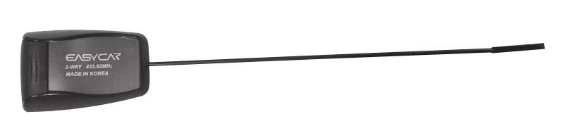
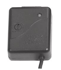
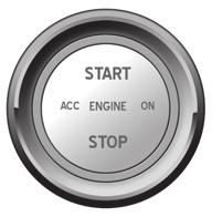
7 Easy Door Lock Sensor, LED Light Connector (CN5) Easy Door Lock Sensor Doors can be locked (armed) or unlocked (disarmed) without the remote or car keys with this function. Simply input the 4 digit pass-code by knocking on the Easy Door Lock Sensor on the front windshield. ** On the pager model (E8-B), knocking twice on the sensor will send a call signal to the pager remote. However, it will not operate when the vehicle is on the ON position nor when the engine is running. LED Light The 10 digit blue LED displays various functions such as arming, disarming, valet mode and emergency status (panic, shock, and theft). Start Button (CN8) 1. Push button ON/OFF 1-1) Engine ON To start your vehicle, press the brake and press the Push-to-Start button. The STOP will illuminate to red. Once the parking brake (automatic transmission) or the emergency brake (manual transmission) is released, the <Ignition On> <Ignition Off> red illumination will disappear. Once the red "STOP" illumination disappears, you will not be able to stop the engine. Dual Shock Sensor (CN6) Install the sensor in a central location and adjust its sensitivity after opening the door in accordance with different shocks and status of LEDs on the shock sensor. It senses shocks by two steps (strong and weak shock). Antenna Module (CN7) 1-2) Engine OFF To turn your engine off, press the brake and press the Push-to-Start button. Once the parking brake (automatic transmission) or the emergency brake (manual transmission) is engaged, the green illumination will appear on START. 2. OFF ACC ON OFF 2-1) ACC To enable the vehicle in the ACC mode, press the Push-to-Start button once without pressing on the brake Mount the antenna horizontally at the top left or right corner of the front windshield. The transmitting distance may decrease if the vehicle has a UV protective coating on the windshield. 2-2) ON To enable the vehicle in the Ignition ON mode, press the Push-to-Start button twice without pressing on the brake. <ACC> <ON> 12 INSTALLATION GUIDE INSTALLATION GUIDE 13
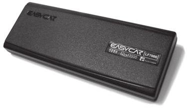
8 Auxiliary Harness (CN9) CN9/1 YELLOW (-250mA) AUX 1 OUTPUT This wire provides (-) 250mA programmable output whenever the transmitter button(s) controlling Aux 1 is pressed. CN9/2 YELLOW/BLACK (-250mA) AUX 2 OUTPUT This wire provides (-) 250mA programmable output whenever the transmitter button(s) controlling Aux 2 is pressed. CN9/3 VIOLET (-250mA) STARTER KILL This wire supplies a (-) 250mA ground as long as the system is armed. CN9/4 BLANK N/A CN9/5 GREY/BLACK (-250mA) AUTO LIGHT CONTROL OUTPUT Utilize this option to stop the auto light function in remote start, reservation start, and turbo start modes. Autolight control (gray/black) Door trigger pin in driver seat LF Module - Smart Door (CN10) For two switch vehicles: Please connect it with folding Switch wire as below Mount the LF module on the front windshield (if the LF module is mounted under the dash, it decreases the transmitting distance). When the Smart Remote is within the communication range (6-8 feet) of the LF module, it will unlock the vehicle. When the Smart Remote is not detected in the communication range (6-8 feet), the vehicle will lock within 12~15 seconds. 14 INSTALLATION GUIDE INSTALLATION GUIDE 15 Note The Smart Door function mode can be activated from the remote. Simply hold the unlock button for 3 seconds to activate the Smart Door mode.
9 Temperature Sensor (CN11): E8-B ONLY This sensor senses the interior temperature of the vehicle. Do not mount the sensor on the floor or the body of the vehicle. 2. Selection For Automatic and Manual Transmission The Jumper wire inside the cover of the main unit is used for Manual transmission vehicles. If the unit is installed on an Automatic transmission vehicle, simply cut the Jumper wire. WARNING! 3. Alternator Sensor 1. Dip Switch Do not reconnect the Jumper wire once it has been cut. It will void all warranty and it is very unsafe. 2. Noise Sensing LED The LED on the cover of the main controller unit is lit when the engine is running and the light is turned off when the engine is off. 4. Programming Noisy Sensing LED IMPORTANT! LED These steps must be completed in order for the product to operate properly. A. Remote Control Registration 1) Press the Start button (OFF ACC ON) 4 times; ON light should be displayed. (Parking light flash once, ready to program the remotes) 2) Press the I or button on the 1st remote. 3) Then press the I or button on the 2nd remote. (When the lock button is pressed on the remote, paking light flash once) 4) Remote programming is now complete. 16 INSTALLATION GUIDE INSTALLATION GUIDE 17
10 B. Easy Door Lock Program (Push button will not operate until Easy Door Lock is programmed) 1) Decide on a passcode, a 4 digit number. (i.e. 1234) 2) Step into the vehicle. 3) Open the driver side door. 4) Press the Start button so that it is on the Ignition ON position. 5) Step out of the vehicle. 6) Knock on the Easy Door Lock a few times until you see all the LED lights flash. 7) LED light will now move from 1 to 0. (Each number will be lit for 2 seconds) 8) Knock on the pad when the number to your passcode is lit. (Each time a number is entered, the LED light will restart from the 1 position) i.e.) On a passcode for a. Tap when the LED light is lit on the 1. b. LED light will restart from the 1 position and move onto 2. c. Tap when the LED light is lit on the 2. d. LED light will restart from the 1 position and move onto 2 and 3. e. Tap when the LED light is lit on the 3. f. LED light will restart from the 1 position and move onto 2, 3 and 4. g. Tap when the LED light is lit on the 4. 9) Once all 4 number passcodes are entered, the siren will beep once and the parking light will flash once. 10) Easy Door Lock programming is now complete. C. Smart Door Lock Registration 1) Open the driver side door. 2) Make sure the Push-to-Start button is set to the OFF position. ( START light should be lit) 3) Press the II or button for 2 seconds on the 1st remote. (Siren will beep twice) 4) Press the II or button for 2 seconds on the 2nd remote. (Siren will beep twice) 5) Smart Door programming is now complete. 5. Remote/Push Button Start Diagnostics When the remote start function is activated and the vehicle emits an error tone (3 chirps); you have the ability to see what the cause of the no-start situation is by counting the amount of flashes of the parking lights from the vehicle. Number of parking lights flashes Cause of Error 1 Engine is on 2 Ignition is to the ON position Door is open (Door wire is active) or Knock Sensor is not 3 programmed 4 Trunk is open (Trunk wire is active) 5 Brake is being pressed (Brake wire is active) 6 CN4/7 wire is not connected 7 Manual transmission mode is enabled and not initialized Parking brake / Emergency brake is off 8 Neutral safety wire has no ground or the neutral safety switch is off 18 INSTALLATION GUIDE INSTALLATION GUIDE 19
11 6. How to Program the Options 4) Within 3 seconds, the vehicle s parking lights will flash as well as chirp; corresponding to the first button pressed followed by chirp(s) and flashes matching the second button pressed. i.e.) Sound Select option vehicle chirps once with one flash (since the I ( ) button was pressed), followed by 4 chirps and 4 flashes (since the IV button was pressed). 5) To end programming mode, press I + IV ( + ) for 2 seconds. It will also end programming with 30 seconds of inactivity. The vehicle s parking lights will flash once and chirp once, stating that it is now out of the programming mode. B. Incorrect Programming Vehicle will chirp once to warn you that the programming was not properly programmed. Please begin the programming once again. C. Factory Setting Reset 1) Press the I + IV ( + ) button simultaneously for 2 seconds to begin the programming mode. The vehicle s parking lights will flash once and chirp once, stating that it is now in programming mode. A. To Program 1) Review the options above and remember the button sequence required for that specific option. 2) Press the I + IV ( + ) button simultaneously for 2 seconds to begin the programming mode. The vehicle s parking lights will flash once and chirp once, stating that it is now in programming mode. 3) Immediately press the two corresponding buttons (one after another). i.e.) Sound Select option press I ( ), then IV ( ). 2) Immediately press IV ( ) twice. Within 3 seconds, the vehicle s parking lights will flash as well as chirp four times, followed by four chirps and flashes. 3) To end programming mode, press I + IV ( + ) for 2 seconds. It will also end programming with 30 seconds of inactivity. The vehicle s parking lights will flash once and chirp once, stating that it is now out of the programming mode. Tech Support available on Monday thru Saturday, 9am ~ 5pm (PST) (562) INSTALLATION GUIDE INSTALLATION GUIDE 21
12 Select Market Trading, Inc. Limited One Year Warranty M/E/M/O This limited warranty is given to the end-user or the retail purchaser (referred to this warranty as "Original Purchaser") that it will be free from defects in material and workmanship for a period of 1 year from the date of the purchase of the new product (excluding accessory items such as harness, keypad, antenna, remote control and pager). A copy of the original proof of purchase and this warranty card with RMA number given by Select Market Trading, Inc. is required to receive warranty service. In the unlikely event that the new product should fail due to defect in material or workmanship, Select Market Trading, Inc. will repair or replace the entire product, where each party will be responsible for one-way shipping. This limited warranty does not cover any physical damage to this product, damage caused by improper installation; improper use; misuse; neglect; repair of cracked, scratched, broken or modified cosmetics; or parts that have been altered or removed; damages done by another device used with this product resulting from use of non Easycar TM - brand parts. This warranty is VOID if you purchased this product as used, floor model sample, or refurbished; if the product has been altered or modified in any way (including but not limited to attempted repair without authorization from Easycar TM - Select Market Trading, Inc. and/or alteration/removal of the serial number). This limited warranty does not cover the vehicle of any damages or liabilities in which this product is installed or being installed. This product does not guarantee avoidance of vehicle collision or accident. If you think your product is eligible for warranty service, please to info@easycar-usa.com to receive an RMA Number with further instructions. Model Number: Serial Number: Date of Purchase: Purchased Store Name: RMA Number: Reason: U S A Name: Address: City: State: Zip: Tel: Important: An RMA (Return Material Authorization) is REQUIRED to receive warranty on defective products, along with proof of purchase and this warranty card.

13
U S A 1 WAY. User's Guide E P
 1 WAY User's Guide E P 400 www.easycar-usa.com We Promise to offer you the highest quality products. We sincerely appreciate you purchasing our Push Button Start System. Our Push Button Start System is
Vehicle Security System
 Installation Instructions Vehicle Security System PROFESSIONAL INSTALLATION STRONGLY RECOMMENDED Installation Precautions: Roll down window to avoid locking keys in vehicle during installation Avoid mounting
2 WAY REMOTE STARTER & ALARM SYSTEM INSTALLATION GUIDE FCC ID NOTICE
 REV. ARS. WAY REMOTE STARTER & ALARM SYSTEM INSTALLATION GUIDE FCC ID NOTICE This device complies with Part 5 of the FCC rules. Operation is subject to the following conditions:. This device may not cause
Installation Manual By Firstech LLC, Version: 1.1
 Installation Manual By Firstech LLC, Version: 1.1 Applicable to the following remote start system: CM800-S Auto Only Starter Control Module This device complies with Part 15 of the FCC rules. Operation
INSTALLATION GUIDE Table of Contents
 CT-3100 Automatic transmission remote engine starter systems. What s included..2 INSTALLATION GUIDE Table of Contents Door lock toggle mode..... 4 Notice...2 Installation points to remember. 2 Features..2
INSTALLATION GUIDE. FCC ID NOTICE
 REV.5 RS. ADVANCED REMOTE STARTER INSTALLATION GUIDE www.security.soundstream.com FCC ID NOTICE This device complies with Part 5 of the FCC rules. Operation is subject to the following conditions:. This
DLKEK3HN INSTALLATION INSTRUCTIONS
 DLKEK3HN INDEX: INSTALLATION INSTRUCTIONS WIRING INSTRUCTIONS... PG 2-5 LED STATUS INDICATOR... PG 6 VALET/OVERRIDE BUTTON... PG 6 SHOCK SENSOR... PG 7 PROGRAMMABLE JUMPER-PINS... PG 7 PROGRAMMING REMOTE
Installation Manual By Firstech LLC, Version: 1.1
 Installation Manual By Firstech LLC, Version: 1.1 Applicable to the following remote start system: CS600-S This device complies with Part 15 of the FCC rules. Operation is subject to the following conditions;
Red #22 Power. Red #14. Brown #18. Ign/Acc/Start. White#14. Tachometer Foot-Brake Door Pin Pos Trunk/Hatch (open) (-) while running Lock Arm
 (-) while running Lock Arm") E400 RFK1004 WIRING / CONNECTION GUIDE AUTOMATIC & MANUAL TRANSMISSION REMOTE STARTER & ALARM QUICK INSTALLATION GUIDE GUIDE # 69151 Power (utility) Red #22 OUTPUT INPUT Power Red #14 1 Yellow #14 Starter
E400 RFK1004 WIRING / CONNECTION GUIDE AUTOMATIC & MANUAL TRANSMISSION REMOTE STARTER & ALARM QUICK INSTALLATION GUIDE GUIDE # 69151 Power (utility) Red #22 OUTPUT INPUT Power Red #14 1 Yellow #14 Starter
CM4200 and CM1000S Starter Control Module Installation Manual
 Version Final - VF CM4200 and CM1000S Starter Control Module Installation Manual This manual is for authorized CompuStar dealers. Please thoroughly review this manual before beginning installation. If
INSTALLATION MANUAL. Model: PLUS For Technical Assistance, please call (800) , or visit
 , or visit") R Vehicle Security INSTALLATION MANUAL Model: PLUS-4700 This device complies with part 15 of the FCC rules. Operation is subject to the following two conditions: (1) This device may not cause harmful interference;
R Vehicle Security INSTALLATION MANUAL Model: PLUS-4700 This device complies with part 15 of the FCC rules. Operation is subject to the following two conditions: (1) This device may not cause harmful interference;
INSTALLATION MANUAL. Remote Mobile Security System. Model: PL30
 Remote Mobile Security System INSTALLATION MANUAL Model: PL30 Copyright 1998 Magnadyne Corporation For Technical Assistance (800) 638-3600 For Fax on Demand Technical Assistance (800) 994-9977 (Must be
INSTALLATION MANUAL. Remote Mobile Security System. Model: PL50
 Remote Mobile Security System INSTALLATION MANUAL Model: PL50 Copyright 2000 Magnadyne Corporation For Technical Assistance (800) 638-3600 For Fax on Demand Technical Assistance (800) 994-9977 (Must be
INSTALLATION MANUAL. Model: PLUS Vehicle Security
 R Vehicle Security INSTALLATION MANUAL Model: PLUS-5000 Copyright 1999 Magnadyne Corporation For Technical Assistance (800) 638-3600 For Fax on Demand Technical Assistance (800) 994-9977 (Must be a Registered
Automatic / Manual Transmission Remote Start with Keyless Entry Installation Guide for models: ca5153 ca5153sst
 PROFESSIONAL SERIES Automatic / Manual Transmission Remote Start with Keyless Entry Installation Guide for models: ca5153 ca5153sst 2012 Audiovox Electronics Corporation. All rights reserved. 1 Table of
Vehicle Security System
 Installation Instructions Vehicle Security System PROFESSIONAL INSTALLATION STRONGLY RECOMMENDED Installation Precautions: Roll down window to avoid locking keys in vehicle during installation Avoid mounting
Remote Start with Keyless Entry Installation Guide ca5054
 PROFESSIONAL SERIES Remote Start with Keyless Entry Installation Guide ca5054 2014 Voxx Electronics Corporation. All rights reserved. 1 Table of Contents Before You Begin...3 Wire Connection Guide...4
FOR AUTOMATIC TRANSMISSION AND DIESEL ENGINE VEHICLES
 #STARTC2003-TW TWO-WAY FM/FM REMOTE CONTROL VEHICLE STARTER & ALARM SYSTEM INSTALLATION GUIDE FOR AUTOMATIC TRANSMISSION AND DIESEL ENGINE VEHICLES THIS UNIT MUST BE INSTALLED BY AN AUTHORIZED MICRO ALARM
MEGA 462 REMOTE CONTROL AUTO ALARM SYSTEM INSTALLATION & OPERATION INSTRUCTIONS WIRING DIAGRAM. White. H1 5 Pin White. H6 2 Pin White.
 MEGA 462 REMOTE CONTROL AUTO ALARM SYSTEM INSTALLATION & OPERATION INSTRUCTIONS WIRING DIAGRAM H7/1 Green : (-) 200mA Pulse H7 3 Pin H7/3 Blue : (-) 200mA Unlock White LED Indicator Valet Switch H6 2 Pin
Remote Start with Keyless Entry Installation Guide CA 5051
 PROFESSIONAL SERIES Remote Start with Keyless Entry Installation Guide CA 5051 2010 Audiovox Electronics Corporation. All rights reserved. 1 Table of Contents Before You Begin... 3 Wire Connection Guide...
OCT/21/02 MEGA 670L DELUXE 4-CHANNEL CAR ALARM SECURITY SYSTEM. Installation And Operation Manual MEGATRONIX CALIFORNIA, U.S.A.
 OCT/21/02 MEGA 670L DELUXE 4-CHANNEL CAR ALARM SECURITY SYSTEM Installation And Operation Manual MEGATRONIX CALIFORNIA, U.S.A. MEGA 670 1 MEGA 670 2 OCT/21/02 OCT/21/02 WIRING DIAGRAM H7: 10 Pin White
Automatic / Manual Transmission Remote Start with Keyless Entry Installation Guide. ca 5152
 PROFESSIONAL SERIES Automatic / Manual Transmission Remote Start with Keyless Entry Installation Guide ca 5152 1 Table of Contents Before You Begin... 3 Wire Connection Guide... 4 11 Pin Main Harness...
Vehicle Security System
 Installation Instructions Vehicle Security System PROFESSIONAL INSTALLATION STRONGLY RECOMMENDED Installation Precautions: Roll down window to avoid locking keys in vehicle during installation Avoid mounting
WIRING / CONNECTION GUIDE (20-PIN) SECONDARY CONNECTOR
 SECONDARY CONNECTOR") EVO-ONE WIRING / CONNECTION GUIDE (20-PIN) SECONDARY CONNECT (6-PIN) BYPASS RELAY (+) Foot Brake Black IN 750mA (-) Parking lights Pink OUT 750mA (-) Trunk Release/AUX Yellow/Black OUT (-) Hand Brake Brown/
EVO-ONE WIRING / CONNECTION GUIDE (20-PIN) SECONDARY CONNECT (6-PIN) BYPASS RELAY (+) Foot Brake Black IN 750mA (-) Parking lights Pink OUT 750mA (-) Trunk Release/AUX Yellow/Black OUT (-) Hand Brake Brown/
MM1 Installation Instructions
 MM1 Installation Instructions PROFESSIONAL INSTALLATION STRONGLY RECOMMENDED Installation Precautions: Roll down window to avoid locking keys in vehicle during installation Avoid mounting components or
AS-4000 OPERATING INSTRUCTIONS (PS-5000)
") AS-4000 OPERATING INSTRUCTIONS (PS-5000) BASIC OPERATIONS This unit is a state-of-the-art combination of a vehicle alarm and remote starter system. Start by familiarizing yourself with the alarm functions
AS-4000 OPERATING INSTRUCTIONS (PS-5000) BASIC OPERATIONS This unit is a state-of-the-art combination of a vehicle alarm and remote starter system. Start by familiarizing yourself with the alarm functions
Owner s Guide CARS & CA4B5
 PROFESSIONAL SERIES Owner s Guide For Model: CARS & CA4B5 Deluxe Vehicle Remote Start and Keyless Entry System IMPORTANT NOTE: The operation of the Security and Convenience System as described in this
Lt.Blue/Black. White. Orange. LED Blue LED Yellow LED Red
 EVO-ONE RFK1004 WIRING / CONNECTION GUIDE (20-PIN) SECONDARY CONNECT (6-PIN) BYPASS RELAY (+) Foot Brake Black IN 750mA (-) Parking lights Pink OUT 750mA (-) Trunk Release/AUX Yellow/Black OUT (-) Hand
Covers All 430, 440, 441 and CJ Series Advanced Security Systems.
 INSTALL GUIDE Covers All 430, 440, 441 and CJ Series Advanced Security Systems www.ultrastarters.com Technical Support: 866-698-5872 ext 0 support@ultrastarters.com FCC/ID Notice This device complies with
12V PROGRAMMABLE POWER OUT
 Page 1 ACCESSORIES STARTER IGNITION BATTERY WIRES SIDE VIEW BLUE RED YELLOW 30 A 10 A BLUE / WHITE YELLOW WHITE / BLUE WHITE / DOOR TRIGGER See opt. 16 DOOR TRIGGER (input positive) See opt. 16 PARKING
EXTENDED INSTALL GUIDE Revision /2015 FW 51+
 AUTOMATIC/MANUAL TRANSMISSION REMOTE STARTER EXTENDED INSTALL GUIDE Revision 4.02-08/2015 FW 51+ 12V CONSTANT IN RED 1 ( + ) 500mA 12V TO STARTER PURPLE 2 ( + ) 500mA 12V TO IGNITION PINK 3 SYSTEM GROUND
Remote Start Installation Guide ca 4552
 PROFESSIONAL SERIES Remote Start Installation Guide ca 4552 ca4552. 2011 Audiovox Electronics Corporation. All rights reserved. 1 Before You Begin... 3 Wire Connection Guide... 4 4 Pin Main Harness...
FM SECURITY AND REMOTE START SYSTEM
 FM SECURITY AND REMOTE START SYSTEM INSTALLATION MANUAL BEFORE INSTALLING THIS PRODUCT PLEASE READ THIS INSTALLATION MANUAL THOROUGHLY!! This system is intended for installation on vehicles equipped with
MEGA WAY LCD PAGER ALARM WITH REMOTE ENGINE STARTER. Operation Manual MEGATRONIX CHATSWORTH, CA U.S.A. MEGA 2700 OPERATE 1
 MEGA 2700 2-WAY LCD PAGER ALARM WITH REMOTE ENGINE STARTER Operation Manual MEGATRONIX CHATSWORTH, CA U.S.A. MEGA 2700 OPERATE 1 2 WARNINGS: As with any product that performs automatic functions, there
CS-865RKE Series II REMOTE KEYLESS ENTRY SYSTEM
 INTRODUCTION: CS-865RKE Series II REMOTE KEYLESS ENTRY SYSTEM INSTALLATION & OPERATING INSTRUCTIONS CONGRATULATIONS on your choice of a Remote Keyless Entry System by Crimestopper Security Products Inc.
AK-105B. ADVANCED KEYS Smart Keyless Entry + Push Start Ignition System USER MANUAL. Product Features:
 AK-105B REV: A05-15-0901 ADVANCED KEYS Smart Keyless Entry + Push Start Ignition System USER MANUAL Product Features: Smart Keyless Locking/Unlocking Compact Sized Smart Keys Dual-Antenna Setup Bypass
Security and Remote Start Installation Guide for models: ca6554
 PROFESSIONAL SERIES Security and Remote Start Installation Guide for models: ca6554 2014 Voxx Electronics Corporation. All rights reserved. 1 Table of Contents Before You Begin...4 Wire Connection Guide...5
CA 650 Owner's Manual
 Remote Vehicle Control System CA 650 Owner's Manual Vehicle Security and Remote Start System with Two Way Confirming LCD Remote Control IMPORTANT NOTE: The operation of the Security and Convenience System
Installation Manual By Firstech LLC, Version: 1.0
 Installation Manual By Firstech LLC, Version: 1.0 Applicable to the following control modules: - CM4200-DX (remote start) - CM5200 (DT remote start with Blade) - CM4000 (alarm and remote start) - CM5000
Responder LE Model 5701 Security and Remote Start. Installation Guide
 Responder LE Model 5701 Security and Remote Start Installation Guide Note: This product is intended for installation by a professional installer only! Any attempt to install this product by any person
Security and Remote Start Installation Guide for models: ca 6552 ca 6552 SST
 PROFESSIONAL SERIES Security and Remote Start Installation Guide for models: ca 6552 ca 6552 SST ca6552/6552sst. 2011 Audiovox Electronics Corporation. All rights reserved. 1 Table of Contents Before You
Owner s Guide. ca5354
 PROFESSIONAL SERIES Owner s Guide for models: ca5354 Deluxe Vehicle Remote Start System with 900Mhz 2 Way Confirming LED Remote Control IMPORTANT NOTE: The operation of the Security and Convenience System
TWO-WAY LED AUTOMATIC TRANSMISSION REMOTE STARTER. User Guide WARNING
 TWO-WAY LED AUTOMATIC TRANSMISSION REMOTE STARTER User Guide WARNING It is the responsibility of the vehicle operator to ensure their vehicle is parked in a safe and responsible manner. 1. When leaving
2 Way Security and Keyless Entry Installation Guide ca 1553
 PROFESSIONAL SERIES 2 Way Security and Keyless Entry Installation Guide ca 1553 2012 Audiovox Electronics Corporation. All rights reserved. 1 Table of Contents Before You Begin... 3 Wire Connection Guide...
CS-2001 REMOTE CONTROL ALARM SYSTEM INSTALLATION & OPERATING INSTRUCTIONS INTRODUCTION
 CS-2001 REMOTE CONTROL ALARM SYSTEM INSTALLATION & OPERATING INSTRUCTIONS INTRODUCTION CONGRATULATIONS on your choice of a Gargoyle Remote Alarm System by Crimestopper Security Products Inc. This booklet
Security and Remote Start Installation Guide for models: ca6553 ca6553sst
 PROFESSIONAL SERIES Security and Remote Start Installation Guide for models: ca6553 ca6553sst 2012 Audiovox Electronics Corporation. All rights reserved. 1 Table of Contents Before You Begin... 4 Wire
VEHICLE SECURITY SYSTEM INSTALLATION MANUAL
 VEHICLE SECURITY SYSTEM WITH REMOTE START & NETWORK INTERFACE INSTALLATION MANUAL BEFORE INSTALLING THIS PRODUCT PLEASE READ THIS INSTALLATION MANUAL THOROUGHLY!! Before You Begin This system is intended
Remote Start Keyless Entry Model 5101 Installation Guide
 Remote Start Keyless Entry Model 5101 Installation Guide This product is intended for installation by a professional installer only! Attempts to install this product by a person other than a trained professional
High Quality Starter and Alarm Systems
 High Quality Starter and Alarm Systems We sincerely appreciate you purchasing our vehicle starter and alarm systems. Our starter and alarm systems are produced with strict quality control and international
6R / 5-BUTTON SERIES VEHICLE SECURITY SYSTEM
 6R / 5-BUTTON SERIES VEHICLE SECURITY SYSTEM Button 1 Button 2 Button 5 Button 3 Button 4 Standard Features: Two 5-Button Remote Transmitters Status indicator (LED) Valet / override switch Multi-tone siren
CA 6550 Owner s Guide
 PROFESSIONAL SERIES CA 6550 Owner s Guide 2 Way LCD Vehicle Security and Remote Start System IMPORTANT NOTE: The operation of the Security and Convenience System as described in this manual is applicable
Owner s Guide CARS & CA2LCD5
 PROFESSIONAL SERIES Owner s Guide For Models: CARS & CA2LCD5 Deluxe Vehicle Remote Start and Keyless Entry System IMPORTANT NOTE: The operation of the Security and Convenience System as described in this
MEGA WAY LCD 4-CHANNEL CAR ALARM SECURITY SYSTEM. Installation Manual MEGATRONIX CALIFORNIA, USA MEGA 2500 INSTALL 1
 MEGA 2500 2-WAY LCD 4-CHANNEL CAR ALARM SECURITY SYSTEM Installation Manual MEGATRONI CALIFORNIA, USA MEGA 2500 INSTALL 1 MEGA 2500 INSTALL 2 INSTALLATION DIAGRAM H8: 10 Pin White Mini Connector H8 10
TWO-WAY LED MANUAL / AUTOMATIC TRANSMISSION REMOTE STARTER. User Guide WARNING
 TWO-WAY LED MANUAL / AUTOMATIC TRANSMISSION REMOTE STARTER User Guide WARNING It is the responsibility of the vehicle operator to ensure their vehicle is parked in a safe and responsible manner. 1. a)
KE 680 DELUXE 4-CHANNEL KEYLESS ENTRY SYSTEM DOOR LOCK RELAYS ON-BOARD. Installation And Operation Manual MEGATRONIX CALIFORNIA, U.S.A.
 KE 680 DELUE 4-CHANNEL KEYLESS ENTRY SYSTEM DOOR LOCK RELAYS ON-BOARD Installation And Operation Manual MEGATRONI CALIFORNIA, U.S.A. KE 680 1 INSTALLATION DIAGRAM H8: 10 Pin White Mini Connector H8 10
Owner s Guide. ca6154
 PROFESSIONAL SERIES Owner s Guide For Models: ca6154 Deluxe Vehicle Security and Remote Start System IMPORTANT NOTE: The operation of the Security and Convenience System as described in this manual is
Model Installation Guide
 Model 4400 Installation Guide NOTE: This product is intended for installation by a professional installer only! Any attempt to install this product by any person other than a trained professional may result
Master Install Guide CM3 Series - CM4200 CM1000A
 By: Master Install Guide CM3 Series - CM4200 CM1000A FOR DISTRIBUTION TO AUTHORIZED COMPUSTAR DEALERS ONLY 04/27/06-1 - - 2 - TABLE OF CONTENTS Install Checklist...Page 4 Remote Programming Procedure 1WAM4R,
Owner s Guide. ca5154
 PROFESSIONAL SERIES Owner s Guide for models: ca5154 Automatic / Manual Transmission Remote Start and Keyless Entry System IMPORTANT NOTE: The operation of the Security and Convenience System as described
FEB.20, 2003 COMMANDO MODEL FM-870 REMOTE ENGINE STARTER WITH ALARM SYSTEM INSTALLATION MANUAL RST872 1
 COMMANDO MODEL FM-0 REMOTE ENGINE STARTER WITH ALARM SYSTEM INSTALLATION MANUAL RST2 1 HJKL TABLE OF CONTENTS: INSTALLATION DIAGRAM..... 4 H1: 6 PIN HEAVY GAUGE WIRING CONNECTION.... 6 H1/1 Violet Wire
PROFESSIONAL INSTALLATION STRONGLY RECOMMENDED
 Installation Instructions CPL Master Module PROFESSIONAL INSTALLATION STRONGLY RECOMMENDED Installation Precautions: Roll down window to avoid locking keys in vehicle during installation Avoid mounting
TWO-WAY LCD AUTOMATIC TRANSMISSION REMOTE STARTER. User Guide
 TWO-WAY LCD AUTOMATIC TRANSMISSION REMOTE STARTER User Guide A note concerning the battery inside the transmitter: Depending on your usage of the transmitter, the battery can last anywhere between 3 to
Matrix RSIII Installation Guide
 Matrix RSIII Installation Guide 2003 Directed Electronics, Inc. Vista, CA N909554 2-03 The Bitwriter (p/n 998T) requires chip version 1.4 or newer to program this unit. www.directechs.com DirectFax 800-999-1329
User Guide TWO-WAY LED AUTOMATIC/MANUAL TRANSMISSION REMOTE STARTER WITH FULL ALARM SYSTEM
 TWO-WAY LED AUTOMATIC/MANUAL TRANSMISSION REMOTE STARTER WITH FULL ALARM SYSTEM User Guide WARNING It is the responsibility of the vehicle operator to ensure their vehicle is parked in a safe and responsible
ADVANCED KEYLESS ENTRY SYSTEM INSTALL GUIDE.
 REV.2009.04.10 KE-6 ADVANCED KEYLESS ENTRY SYSTEM TM INSTALL GUIDE www.ultrastarters.com FCC ID NOTICE This device complies with Part 15 of the FCC rules. Operation is subject to the following conditions:
Advanced Remote Vehicle Starting System
 INSTALLATION GUIDE 1600 Advanced Remote Vehicle Starting System 1600M AUTOMATIC AND MANUAL TRANSMISSION MODELS WWW.ULTRASTARTERS.COM See website for a full size printable version of this manual. WARNING!!
AS-1535 SH User Guide
 A U T O M A T I C T R A N S M I S S I O N M U L T I C H A N N E L R E M O T E S T A R T E R S Y S T E M AS-1535 SH User Guide Transmitter Part Number and Module Serial Number... 2 Introduction... 2 Basic
RF-425LCD PROFESSIONAL VEHICLE SECURITY SYSTEM INSTALLATION MANUAL (FOR AUTHORIZED DEALERS ONLY)
") RF-425LCD PROFESSIONAL VEHICLE SECURITY SYSTEM INSTALLATION MANUAL (FOR AUTHORIZED DEALERS ONLY) THIS PRODUCT IS DESIGNED FOR PROFESSIONAL INSTALLATION ONLY 1 BLUE...TRUNK/HOOD TRIGGER (-) INPUT BLACK/BLUE...4TH
RF-425LCD PROFESSIONAL VEHICLE SECURITY SYSTEM INSTALLATION MANUAL (FOR AUTHORIZED DEALERS ONLY) THIS PRODUCT IS DESIGNED FOR PROFESSIONAL INSTALLATION ONLY 1 BLUE...TRUNK/HOOD TRIGGER (-) INPUT BLACK/BLUE...4TH
INSTALLATION MANUAL. This unit is designed for professional installation only and must be installed by an authorized Silencer dealer.
 INSTALLATION MANUAL SL- 3 3-Channel Security with Keyless Entry System This unit is designed for professional installation only and must be installed by an authorized Silencer dealer. For Warranty information:
TWO-WAY LED MANUAL TRANSMISSION REMOTE STARTER. User Guide WARNING
 TWO-WAY LED MANUAL TRANSMISSION REMOTE STARTER User Guide WARNING It is the responsibility of the vehicle operator to ensure their vehicle is parked in a safe and responsible manner. 1. When leaving the
Model 5103 Installation Guide
 Model 5103 Installation Guide This product is intended for installation by a professional installer only! Attempts to install this product by a person other than a trained professional may result in severe
User Manual. Applicable to the following remote(s) 600R / 700R FCC ID : VA5JR260A433. Toll Free : th Ave S Kent, WA 98032
 600R / 700R FCC ID : VA5JR260A433. Toll Free : th Ave S Kent, WA 98032") 8102REUSL000200/ FT-600R V1 By Firstech LLC Version 2.0 (C-04) www.firstechonline.com www.compustar.com User Manual Applicable to the following remote(s) 600R / 700R Toll Free : 888-820-3690 21903 68th
8102REUSL000200/ FT-600R V1 By Firstech LLC Version 2.0 (C-04) www.firstechonline.com www.compustar.com User Manual Applicable to the following remote(s) 600R / 700R Toll Free : 888-820-3690 21903 68th
"WE'VE GOT THE EDGE ON SECURITY" INSTALLATION MANUAL AL-700 ATV / AL-900 ATV / AL-1000 ATV
 "WE'VE GOT THE EDGE ON SECURITY" INSTALLATION MANUAL AL-700 ATV / AL-900 ATV / AL-1000 ATV COPYRIGHT: OMEGA RESEARCH & DEVELOPMENT INC. 1997 Contents 5 WIRE HARNESS CONNECTIONS Black Wire (Chassis Ground)...
RS-351-EDP. Installation Guide
 RS-351-EDP Keyless Entry & Remote Start Installation Guide June 25, 2013 Temporary cover. Color cover is in a separate file. Table Of Contents Installation Considerations... 3 6 Pin Main Wire Harness...
INSTALLATION INSTRUCTIONS
 Total System Reset The 30 features, including the Selectable Coded Override, may be easily returned to the default settings. To perform this Total System Reset, follow these steps: Step 1 - Locate the
INTRODUCTION ALARM WIRING DESCRITION
 6PIN CONNECTION RED BLUE YELLOW BROWN PINK INTRODUCTION The newest technological are integrated in our Two Way Alarm and Remote Engine Start alarm system. They are fully programmable for your customers
Model APS-101N Installation Manual
 Programmable Features Model APS-101N Installation Manual Select By Operating Transmitter Press Lock Button Press Unlock Button Siren Indications 1 Chirp 2 Chirps Factory Default 1) Arming Method Passive
Remote Start Installation Guide CA 4051
 PROFESSIONAL SERIES Remote Start Installation Guide CA 4051 2010 Audiovox Electronics Corporation. All rights reserved. 1 Before You Begin... 3 Wire Connection Guide... 4 4 Pin Main Harness... 5 3 Pin
ADD-ON REMOTE STARTER TO AFTERMARKET SYSTEM
 MEGATRONIX RS 110 ADD-ON REMOTE STARTER TO AFTERMARKET SYSTEM Installation and Operation Manual MEGATRONIX CHATSWORTH, CA U.S.A. RS110 ADD-ON REMOTE CAR STARTER For Vehicles Equipped With Automatic Transmission
User Manual. Applicable to the following remote(s) 600R (1Way 4Button Remote) FCC ID : VA5JR260A433
 600R (1Way 4Button Remote) FCC ID : VA5JR260A433") 8102REUSL000200/ FT-600R V1 By Firstech LLC Version 1.0 www.firstechonline.com www.compustar.com User Manual Applicable to the following remote(s) 600R (1Way 4Button Remote) Toll Free : 888-820-3690 21911
8102REUSL000200/ FT-600R V1 By Firstech LLC Version 1.0 www.firstechonline.com www.compustar.com User Manual Applicable to the following remote(s) 600R (1Way 4Button Remote) Toll Free : 888-820-3690 21911
COMMANDO REMOTE CONTROL ENGINE STARTER. Limited Warranty Statement MADE IN THE U.S.A. IMPORTANT KEEP YOUR INVOICE WITH THIS WARRANTY STATEMENT!
 Limited Warranty Statement GNU COMMANDO LINE WARRANTY STATEMENT GNU warrants this product to be free from defects in material and workmanship for a period of one (1) year from the date of sale to the original
AviStart 6500 Installation Manual
 Table of Contents Important Information... 1 Recommended Installation Tools... 1 Recommended Procedures... 1 Main Wiring Diagrams.... 2 Pin Connectors... 5 Installation Procedures...7 Control Unit... 7
VS 655 DELUXE 4-CHANNEL CAR ALARM SECURITY SYSTEM. Installation And Operation Manual MEGATRONIX CALIFORNIA, U.S.A. VS 655 1
 VS 655 DELUXE 4-CHANNEL CAR ALARM SECURITY SYSTEM Installation And Operation Manual MEGATRONIX CALIFORNIA, U.S.A. VS 655 1 VS 655 2 INSTALLATION DIAGRAM H8: 10 Pin White Mini Connector H8 10 Pin White
CSI-300 Installation Instructions
 CSI-300 Installation Instructions Kit Contents Installation Precautions: Roll down window to avoid locking keys in vehicle during installation Avoid mounting components or routing wires near hot surfaces
VIPER. Model Installation Guide
 VIPER Model 7900 Installation Guide NOTE: This product is intended for installation by a professional installer only! Any attempt to install this product by any person other than a trained professional
CA 170 Owner's Manual
 Remote Vehicle Control System CA 170 Owner's Manual Vehicle Security System with Two Way Confirming LCD Remote Control IMPORTANT NOTE: The operation of the Security and Convenience System as described
ALARM UPGRADE FOR FACTORY REMOTE KEYLESS ENTRY SYSTEM INSTALLATION PRECAUTIONS & WARNINGS
 CS-882 OEM ALARM UPGRADE FOR FACTORY REMOTE KEYLESS ENTRY SYSTEM INSTALLATI PRECAUTIS & WARNINGS NOTE: This system does not improve or affect the range of the factory remote keyless entry transmitters.
Owner s Guide PROCOMP
 professional series Owner s Guide PROCOMP Deluxe Vehicle Security and Remote Start System with 900 Mhz 2 Way Confirming OLED Remote Control IMPORTANT NOTE: The operation of the Security and Convenience
Model 2100 Installation Guide
 Model 2100 Installation Guide 2001 Directed Electronics, Inc. Vista, CA N2100 4-01 Rev. N/C 1.1 table of contents What Is Included..................... 2 Wiring Quick Reference Guide............ 3 Primary
User Guide 1 WAY FM MANUAL TRANSMISSION REMOTE STARTER. Table of Contents. Introduction
 1 WAY FM MANUAL TRANSMISSION REMOTE STARTER User Guide Table of Contents... 1 Introduction... 1 Using the Remote Control... 2 Multi-Level Features (default state)... 2 Remote-Starting Your Vehicle... 3
Owner s Guide CA 5055
 PROFESSIONAL SERIES Owner s Guide For Model: CA 5055 Vehicle Remote Start and Keyless Entry System IMPORTANT NOTE: The operation of the Security and Convenience System as described in this manual is applicable
AUTOMATIC AND MANUAL TRANSMISSION MODELS* *MUST USE M SERIES REMOTE STARTER!
 REV.2011.7.22 80 SERIES Advanced Remote Starters & Vehicle Security Systems AUTOMATIC AND MANUAL TRANSMISSION MODELS* *MUST USE M SERIES REMOTE STARTER! WARING: NEVER USE AN AUTOMATIC TRANSMISSION STARTER
Owner s Guide PR1BZ PR1BZLR
 Owner s Guide For Models: PR1BZ PR1BZLR PRORS RF Upgrade Kit IMPORTANT NOTE: The operation of the Security and Convenience System as described in this manual is applicable to most vehicles. However, due
AS-1535 SH. Installation Guide
 AUTOMATIC TRANSMISSION REMOTE STARTER SYSTEM AS-1535 SH Installation Guide Notice The manufacturer will accept no responsibility for any electrical damage resulting from improper installation of the product,
ONE-WAY DELUXE SECURITY SYSTEM
 ONE-WAY DELUXE SECURITY SYSTEM CONGRATULATIONS on your choice of a CrimeStopper Remote Security System. This booklet contains all the necessary information for using, and installing your security system.
Button 1 Button 2. Button 3 Button 4. Programmed Remote Transmitter. Button Function Condition
 WWW.STELLAR.COM Button Function Condition 1 a. Arm and lock doors b. Car finder with sound c. Temporary stop alarm from sounding d. Remote lock doors 1 for 2 sec. Panic Anytime a. Alarm is disarmed b.
MEGA WAY LCD 4-CHANNEL CAR ALARM SECURITY SYSTEM. Operation Manual MEGATRONIX CALIFORNIA, USA MEGA 2500 OPERATE 1
 MEGA 2500 2-WAY LCD 4-CHANNEL CAR ALARM SECURITY SYSTEM Operation Manual MEGATRONIX CALIFORNIA, USA MEGA 2500 OPERATE 1 MEGA 2500 OPERATE 2 OPERATION: A. TRANSMITTER OPERATION: Transmitter Button System
ca 5550SST Owner s Guide
 PROFESSIONAL SERIES ca 5550SST Owner s Guide Deluxe Vehicle Remote Start System with 900Mhz 2 Way Confirming LCD Remote Control IMPORTANT NOTE: The operation of the Security and Convenience System as described
PROFESSIONAL INSTALLATION STRONGLY RECOMMENDED
 100755-2 Installation Instructions PC 4200 PROFESSIONAL INSTALLATION STRONGLY RECOMMENDED Installation Precautions: Roll down window to avoid locking keys in vehicle during installation Avoid mounting
Car Alarm System PCI0768/A
 Car Alarm System Code hopping PCI0768/A Contents User's Manual Important notice --------------------------------------- Key features --------------------------------------------- Technical specifications