NOTE: The glazing material provided in both sidelites and sliding panels of all SLM sliding doors comply with the requirements in the Performance
|
|
|
- Juliana Hines
- 6 years ago
- Views:
Transcription
1
2 NOTE: The glazing material provided in both sidelites and sliding panels of all SLM sliding doors comply with the requirements in the Performance Specifications and Methods of Test for Safety Glazing Materials Used in Buildings. (Ansi Z97.1). It is imperative that the glass installed in all SLM sliding panels and sidelites also comform to the Performance Specifications and Methods of Test for Safety Glazing Materials Used in Buildings (Ansi Z97.1).


3 1. INTRODUCTION 1.1 General This manual is for the Gildor SLM sliding door drive unit: -Supplies instructions for the assembly, commissioning, maintenance and troubleshooting. -Is only to be used only by trained personnel in the automatic door trade familiar with the assembly and construction of automatic doors. -Explains basic instructions for assembly and turn in as well as various instructions for optional equipment. -The instructions for optional equipment are included in the packaging of the optional kits. Referring to the basic instruction, they describe the assembly and commissioning of the respective option. -Uses the following signs in order to point out certain dangers and important remarks: Warning: Involving danger to life and limb. Caution: A situation where material could be damaged or the function impaired. Note: Hints that help out with the work. -An additional manual is available for the customer, owner or end user. -To be installed in accordance to ANSI standards and all local building and safety codes.
4 1.2 Specification and limits to applications: Door Package Type Standard Door Package Size OFW X OFW Net Clear Opening Width Estimated weight of Active Leaf for Standard Package Maximum Weight Per Sliding Leaf Single Slide One moving leaf Right/Left Opening 6'0" X 77 7/8" 7'0" X 77 7/8" 8'0" X 77 7/8" 8'6" X 77 7/8" 29 1/4" 35 1/4" 41 1/4" 44 1/4" 98 Pounds 110 Pounds 122 Pounds 128 Pounds 330 Pounds Bi Parting Two Moving Leaf 12'0" X 77 7/8" 14'0" X 77 7/8" 16'0" X 77 7/8" 60" 72" 84" 100 Pounds 112 Pounds 124 Pounds 220 Pounds Bi Parting Two Moving Leaf Two Motor Call for Information on Packages Sizes 330 Pounds Single Slide Telescopic Two Moving Leaf Right/Left Opening 7'0" X 77 7/8" 8'0" X 77 7/8" 9'0" X 77 7/8 10'0" X 77 7/8 11'0" X 77 7/8 12'0" X 77 7/8 50 1/2" 58 1/2" 66 1/2" 74 1/2" 82 1/2" 90 1/2" 86 Pounds 95 Pounds 103 Pounds 112 Pounds 120 Pounds 129 Pounds 220 Pounds Bi Parting Telescopic Four Moving Leafs 12'0" X 77 7/8" 14'0" X 77 7/8" 16'0" X 77 7/8" 18'0" X 77 7/8" 20'0" x 77 7/8" 85 1/2" 101 1/2" 117 1/2" 133 1/2" 149 1/2" 79 Pounds 87 Pounds 96 Pounds 105 Pounds 113 Pounds 132 Pounds Bi Parting Telescopic Four Moving Leaf Two Motor Call For Information on Packages Sizes 220 Pounds Technical data -Electrical connection is supplied 110 V, 50/60 by others, all cable connection are Hz, 10A supplies with package -Power consumption 200 W -Max. Driving power (static) 150 N -In the event of a power failure, the battery backup (if installed) guarantees full operation for at least 30 min. -Operating temperature range + 5 F to F 15 C to 75 C- The package may only be used in Max. Relative Dry rooms humidity 65% The application limits of the SLM drive unit for sliding doors are defined for a long life of the door package, any applications beyond these limits are not advisable.
. The different configurations and options are supplied in accordance with the order. 1. Main Profile 7. Connection Box 2.")
 A=Net Outside Frame 4. Front Cover 11. Battery Backup (Optional) Width 5. Bottom Angle 12. Drive Belt 6.")
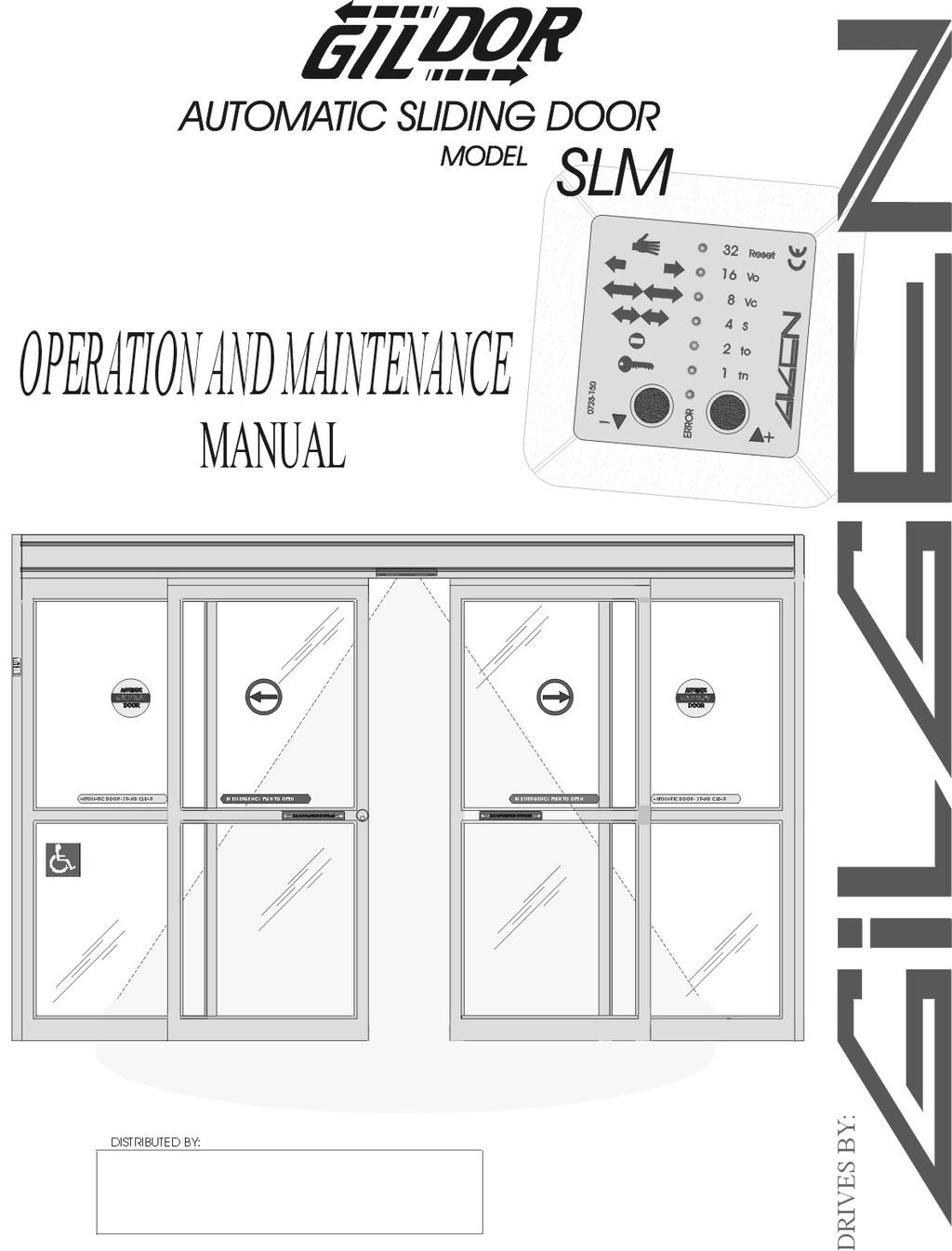
5 1.3 Product Description The SLM drive unit is a modular design with DC motor, microprocessor control unit and electronic control panel with patented bus-system (two-wire line). The different configurations and options are supplied in accordance with the order. 1. Main Profile 7. Connection Box 2. Trolley Assembly 8. Motor Assembly 3a. Header Back (Slimline) 9. Control Box 3b. Header Back (Supporting 10. Electric Solenoid Lock (Optional) A=Net Outside Frame 4. Front Cover 11. Battery Backup (Optional) Width 5. Bottom Angle 12. Drive Belt 6. Carrier 13. End Pulley LW=Net Clear Passage Width
6 1.4 SLM GENERAL INFORMATION FIG. 1 shows the different configuration of door packages available from Gildor for the sliding door systems. Operators can be right or left handed single sliding or Bi parting. Packages can be either fixed sidelite (sidelites to the interior of the building) or full breakout (sidelites to the exterior of the building). All the SLM door packages are ready for installation when delivered to you from Gildor. All material is completely prepped and all hardware is installed. If options are ordered they are completely installed and wired prior to shipping. Before attempting to install door package check to see that all equipment has been properly sent and installed. Check to see that the door package is prepped right and that the package overall size is correct.
7 2. ASSEMBLY 2.1 INSTALLATION OF SLM HEADER Open all packages and inspect for proper shipping per order, completeness, and damage. This should be done at the time the equipment is received at your facility from the factory, to allow ample time to reorder any missing or damage material. Upon arrival at the installation site, first measure all openings in both width and height, to assure proper clearances for door packages. The openings must be plumb and square and the floor height can not vary more than 1/4 from the highest point to the lowest point. It is also necessary to determine the high point area in the floor before the door header is installed as the height of the door package is determined from the high point of the finished floor. If the floor height varies more than 3/8 then leveling of the floor is necessary, before the door package can be installed. It is suggested that the rough opening be 1/2 wider than the door package frame dimension and 1/2 higher than the door header measured from the high point of the floor. If the door package has a transom the rough opening height is not as important as the Gildor transom package is very easy to modify at the installation site. Rough openings can vary with different mounting surfaces.

8 Note: The SLM header requires a minimum of 3/8 clearance above the header in order for the hinged cover to open and close properly. If the proper clearance is not given above the header the cover will not be able to completely open making it difficult for future service. When sealing top of header make sure that the sealant does not interfear with the acess cover opening. Back of header can be sealed flush
.")

9 2.2 Jamb Tube Preparation and Installation The Gildor jamb tubes are handed, making it important to install each jamb on the correct side of the header. The header mounting holes in the jamb tube are offset slightly. The mounting holes closest to the edge of the jamb tube always face the access cover of the Gildor header. (See Fig. 1). This is to assure the door leafs line up with the jamb tube. If the jambs extend past the top of the header for a transom installation, the access cover can open fully and will not be restricted by transom metal mounted on top of the Gildor header. If a transom package is used from Gildor, a two piece Top Can is supplied. The base portion of this Top Can assembly is installed first. This top can base is cut to the rough opening width and installed center lined on center-line of jamb tubes or glass line. Next cut both jamb tubes 1/2 short of the inside web of the this top can base. This allows for leveling of the header, once door header is stood up and inserted inside of can. (See Fig. 2). Bottom Can may also be used in the Gildor transom. This is a 3 piece aluminum storefront system and works the same way as the Top Can. The maximum width of transom metal that can be used and mounted directly on top of the header is 4 1/2. If wider metal is used, than a 3/8 gap must be made between the header and transom metal. Fig 1 Fig 2 Once both jambs are installed, then the entire header, with jambs installed, can be stood up and set into opening. Use a 4 foot level to level both jamb tubes and header, making sure to shim the header height from the high point of the floor. To correctly determine the header height you must measure across the floor to the bottom of the header every 24, when you have an uneven floor. Your header height then is set from the highest point measured by installing shims under jamb tubes and leveling header. It is then necessary to anchor the jamb tubes to the perimeter framing, walls or steel. It is suggested to anchor both jamb tubes at 3 below the header, at 24 from the floor and one every 24 between the first two installed. If a transom is part of the package, then an anchor should be installed at 3 above the header and every 30 to the top of transom. A minimum 1/4 anchor should be used in all areas. Proper shimming between mounting surface and jamb tubes is necessary for a strong secure installation.
10 2.3 SIDELITE INSTALLATION FIXED SIDELITE DOOR PACKAGE (O SX or SX O and O SX SX O) After header and jamb tubes are in place, plumb, square and anchored, open the access cover and lock open. Now the bottom floor track must be anchored. First, measure in from the interior of the 1 3/4 x 4 1/2 jamb tube 3/16 on left and right jamb. Using a chalk line, snap a line on these marks the entire width of the door package. Place each bottom track on this line, with the open face of bottom track facing the exterior and 1/4 from the inside face of the jamb tube. Anchor in through the top of the track using 1/4 cement anchors and #10 x 1 1/2 phillips flat head sheet metal screws. Be sure to tighten screws fully into the counter sink so as not to interfere with the door bottom guide wheels. Now remove the top 1/4 x 20 x 1 1/2 screws from the top of the fixed door panel. Also remove the breakout switch assembly from the upper outside face lead style, pull all the holding beam wires through this hole also. This is done so the wires will not be pinched and can easily be run up into the header once the fixed panel is in place and anchored. Pick the fixed panel up and place it over the bottom guide track, making sure it sits fully over the bottom track, tilt the panel up under the header. While doing this, check to see that the top mounting brackets line up with the holes under the header. (Note that the 1/4 gap left at the bottom track against the jamb was left to give the bottom rear edge of the panel the room to fit between the track and the jamb.) Once the panel is fit under the header make sure the panel is fit tightly to the jamb tube. Now install the 1/4 x 20 x 1 1/2 screws down through the holes in the bottom angle of the header inserting into top mounting bracketsin top web of side panel and tighten. The wires and breakout switch can now be reinstalled. Feed all wires up through the hole in the bottom angle. Pull all wires through leaving enough wires in the door panel for future service of the holding beams. Run all wires in the race provided in the bottom of the header angle and use the snap plastic clips provided to keep all wires in place. Hook up all holding beam wires and breakout switch wires.

11 2.4 SIDELITE INSTALLATION FULL BREAKOUT DOOR PACKAGE (SO SX or SX SO and SO SX SX SO) RECESSED IN CONCRETE TYPE After header and jamb tubes are in place, plumb, square and anchored, open the access cover and lock open. Next the bottom floor track must be installed. First measure in from the interior face of the 1 3/4 x 4 1/2 jamb tube 5/8 to exterior face on left and right jamb. Using a chalk line snap a line on these measurements the entire width of the door package. If is recommended notching the concrete to recess the bottom guide track. The door package jamb tubes come standard for a recessed floor track. Notching the concrete can be easily done with a 4 electric grinder, with a concrete dry cutting blade. Lay the track on the snapped chalk line, lining the inside edge of the track on the line and butt the track to the jamb. Mark around the track with a pencil. This is all the needs to be cut out. The cut out must be a 1/2 deep, level and flat. It may be easier to cut the notch deeper and fill it smooth with wet pur rock or quick set concrete. No notching of the concrete is necessary if a 1/2 surface threshold is used. Only 1/4 deep recess is need if a 1/4 threshold is used. However the threshold must be notched to receive the bottom track. The threshold must be run jamb to jamb. The track is handed and is to be installed with the offset towards the exterior. Anchor in through the top of the track using 1/4 cement anchors and #10 x 1 1/2 phillips flat head sheet metal screws. Be sure to tighten screws fully into the counter sink so as not to interfere with the door bottom guide pin.

12 2.5 SIDELITE INSTALLATION FULL BREAKOUT DOOR PACKAGE (SO SX or SX SO and SO SX SX SO) SURFACE APPLIED After header and jamb tubes are in place, plumb, square and anchored, open the access cover and lock open. Next the bottom floor track must be installed. Hold a chalk line on the exterior face of 1 3/4 x 4 1/2 jamb tube on left and right jamb. Snap line the entire width of door package. Set the surface track down butting the track to each jamb and lining the flat edge of the track on the line facing the exterior. The ramp faces interior. This 1/2 surface track only installs under for swing out sidelite and does not go into the door opening. Anchor in through the top of the track using 1/4 cement anchors and #10 x 1 1/2 phillips flat head sheet metal screws. Level the track so the active leaf slides in the track and guide pin does not move up and down as the active leaf slides open and closed.
13 Next, loosen the set screw that sets the bottom pivot pin from turning. Turn the bottom pivot pin all the way down before attempting to install the sidelite door leaf. Remove the top pivot bolt from the top pivot receiver on the sidelite door leaf, Run the holding beam wires out through the top pivot hole of the panel and let hang until panel is stood up. Lift the sidelite door panel up and set it on the bottom sidelite pivot pin. Tilt the panel in place and at the same time run the holding beam wires up through the pivot hole in the bottom angle of the header. Next run the holding beam wires through the top pivot bolt, so that the top pivot bolt threads are facing down. Tilt the panel the rest of the way up, under the header and feed the holding beam wires into the bottom header angle pivot hole, being careful not to pinch the holding beam wires. Once the panel is under the header and the holding beam wires are pulled completely through the top pivot hole, the top pivot bolt can now be installed down through the header bottom angle, and into the panel top pivot receiver and tightened. Do not over tighten this bolt. The panel should align to the jamb tube when closed, with approximately 1/8 between the rear of the panel and the jamb tube. Adjustments can be made by removing the panel and adjusting the top and bottom pivot receivers. Once the panel is installed and aligned against the jamb tube, the panel catch can be installed and adjusted. Install the breakout catch using the 1/4 x 20 x 1 1/2 bolts and nuts. The catch can be adjusted inside to out for proper alignment. Make sure the catch seats fully into the receiver. The catch can also be adjusted to breakout harder or easier. This is done with a small straight blade screwdriver down through the brass ball itself. Clockwise is easier counterclockwise is harder. If is also necessary to put beeswax on the ball itself to lubricate if properly. Pull all wires through leaving enough wires in the door panel for future service of the holding beams. Run all wires in the space provided in the bottom of the header angle and use the snap plastic clips provided to keep all wires in place. Hook up all holding beam wires and breakout switch wires per diagram page.
14 2.6 ACTIVE LEAF INSTALLATION ALL PACKAGES Remove breakout adjustment bracket (#4 Fig.3) from top Breakout Pivot Arm (B.P.A.). Loosen all 3/8 set screws in B.P.A., back out so that none of the set screws protrude from the top of the B.P.A. Slide the door carriers all the way to closed position. Swing the B.P.A. arm 90 degrees to the door leaf. If this is a fixed sidelite door package, pick up the door leaf and slide the bottom guide wheels, into the outside rear bottom corner of the bottom guide. After the guide is in the track, slide the active leaf towards the center of the opening and insert the B.P.A. arm into the rear of the carrier. The front of the door should line up with the front edge of the carrier plastic end cap. Snug the 3/8 set screw closest to the pivot point first (#1 Fig.3) this will keep the door B.P.A. from sliding in the carrier. Next swing the leaf open past 130 degrees and notice the B.P.A. arm raises in the carrier. Slip the breakout adjustment bracket (#4 Fig.3) into place, lining the set screw up with the indentation in the B.P.A. arm. Now, swing active leaf towards the closed position and adjust the breakout bracket (#2 Fig.3) to pick the leaf up lining up with the ball catch. It is important that the top lead edge of the door is perfectly lined up with the edge of the carrier lead edge plastic end cap. Once the height adjustment is made and the door closes evenly with the ball catch, tighten all set screws in the B.P.A. arm. (#3 Fig.3). FIG.3
15 2.7 BEFORE COMMISSIONING Ajustments to the trolley must be made before commissioning the drive unit to assure proper set up. The ajustments are to be made as follows: 1. Loosen 2 10mm bolt #2 and move antiderail wheel until it meets with bottom of main profile track. Do not over torque this wheel as it will cause unnecessary binding. This antiderail wheel must just touch the bottom of the main profile track just so the antiderail roller rolls with the movement of the trolley. 2. Lossen 8mm nut #3 and move up. Loosen 2 10mm bolts #5. Attach door wing to trolley at 2 14mm bolts. 3. Raise or lower door mounting by turning #8mm nut #4 clockwise to raise and counter clockwise to lower. 4. Tighten bolts #5 first then turn nut #3 back down and tighten Trolleys must be adjusted so that lead door stops #3 attached to the trolleys #4 hit each other in the closed position creating a positive stop closed, do not have door wings create positive stop. Also the full open position must be adjusted so that the trolleys #4 stop at both the R.H stop and the L.H. stop at the same time creating the full open position perminent stop.
16 3. Commissioning 3.1 Requirements -any additional control and safety elements have been mounted and connected. Important: If there are no holding beams with door package, a jumper wire link must be inserted across 14 and 17 and 14 and 18 on the control box. -Door roller assemblies, belt brackets and permanent door stops must be tighten securely, anti riser rollers must be touching bottom of roller track and roll with door wings and tightened securely. Do not over tighten. -The sliding wings must move freely without restriction. The location of the remote control panel (BEDIS) is determined by the project management or store manager and mounted and wired. 3.2 Preliminary electrical settings No preliminary settings (door speeds, time delays, partial opening) can be made prior to commissioning (the stops must be set as described in the instructions prior to this page). The travel distance as well as the maximum admissible speed and force are set automatically by the drive unit during setup (reset). Setting-up procedure: The setting-up procedure is carried out when the drive unit is placed into operation for the first time, or after a RESET by means of the BEDIS. -During the first commissioning, all the values on the second level are reset to standard. -If a RESET is made after the door has already been in operation all 2nd level adjustments remain as previously set. Functional performance: 1. Test of all the Hardware elements of the Control unit. 2. All the connected elements are checked (BEDIS, Electric Solenoid Lock, Battery Backup). 3. The door closes as far as the SHUT position with a set-up speed of 0,075m/s.
17 4. With a Solenoid Lock installed and the program switch (BEDIS) in the NIGHT or Exit Only position, the door wings are locked from sliding and remains in this position until a valid opening command (KEY impulse or INTERIOR impulse is made. In all other positions of the program switch the Solenoid lock is unlocked and all impulses open the doors. 5. The door opens with a set-up speed of 0,075m/s as far as the OPEN-position stop. During the opening the locking is checked (first 1 1/2 ) and a means value of friction is determined. 6. The mass is measured with a short acceleration of the wing. This mass also determines the maximum speed. Chart. 1 Total wing weight in lbs. Maximum opening speed Foot/seconds 55 up to up to exceeding The closing speed corresponds to 40% of the maximum opening speed. 3.3 Procedure -Bring the sliding wings into the center position. -Plug in the power plug. -On control Box, LEDs 5V/24V and Power are lit. -On the BEDIS, LED 32 (Reset) starts flashing approx. 5 seconds after plug-in. The installation sets itself up and remains open. LED 32 operating function manual is lit. If another LED is lit along with the flashing LED 32, then the corresponding operation function is set Interferences -The setting-up procedure can be affected by the following interferences: -BEDIS is on a locked operation position (Night/Exit): -Door breakout switch held open or shorted
18 The door closes and remains closed. LED 32 flashes and LED 1 NIGHT or LED 2 EXIT is lit. The setting-up procedure can be completed only after a valid opening command (KEY) or after selecting another operating function, e.g. AUTOMATIC. -The door opens first during set-up:..check the assembly position of the belt coupling as per drawing, to assure that the belt brackets are on the correct side of the belt. Reversed belt brackets will make doors open when they should close and close when they should open. -The sliding wings do not move:..no Holding beams connected or no jumper wire/diode installed across #14 to #17 and /or #14 to #18 on Control Box. -Red LED Error flashes along with the green LED: -See malfunction (Error Codes) indication (Level 4 Section)
19 4. Control unit and remote control Panel BEDIS 4.1 General The SLM drive unit can be operated and set as follows -Without the BEDIS remote control panel -The following program positions can be selected Via inputs 21 and 22 NIGHT/EXIT/AUTOMATIC (full Open). Reset via terminal 25 and 26 (shorting a wire between #25 and #26 will reset doors) See diagram on Control Box -The BEDIS can be used as a temporary programming unit for the setting the 2nd and 3rd level functions (3rd level functions are not described in this manual..consult factory).. After BEDIS has been connected or removed, a cold start (reset by shorting terminals 25 and 26 momentarally) must be made during which the programmed values are preserved. -With BEDIS remote control panel -Via inputs 25 and 26 (patented 2-wire bus) -The operation can be locked as follows: Using a switch (key, momentary contact, etc...) Connected to BEDIS terminals 3and 4. Note: if no switch is connected to terminals 3 and 4 on the bedis a jumper wire must be installed.-by connecting a terminal or a personal computer (e.g. management system) terminal block J5 (terminals 1-4) this requires special software, consult factory. 4.2 BEDIS remote control panel All the function can be identified and set via the BEDIS remote control panel. The numbering of the LED s on the plate corresponds to their binary value. The softswitch numbers and the error numbers are obtained by adding the numbers next to the LED s which are lit. Example: LED s 16/4/1 are lit =21...softswitch number or error number. 21. Communications with the Control Box unit are fail-safe and tamper-proof via a modern bus system (patiented two-wire line). The BEDIS operates at 4 different levels: 1st level = Operation functions (User level) 2nd level = Setting functions (Must be set and left to ANSI Standards) 3rd level = Programing functions At this level, settings can only be made by expert personnel (Gildor after-sales service or an authorized Gildor Distributor..consult factory) 4th level = Malfunction indication Error
20 4.2.1 Operation functions (1st level) The function of the program switch positions correspond to the established Gildor standard. -The functions are symbolically represented on the left-hand side of the BEDIS, next to the LED s. -The function currently selected is indicated by the permanently lit LED next to it. -The buttons + or - are used to select the required program switch position. The corresponding LED lights up. The new setting is accepted after approx. 2 seconds. MANUAL OPERATION Top LED no #32 The installation is at a standstill. The door wings are release and can be moved by hand. Standard installations should use this position after hours to lock doors unless a Solenoid lock is installed. HOLD OPEN LED 16 The installation opens and remains in the open position. TWO WAY AUTOMATIC LED 8 The installation is not locked if there is a Solenoid lock installed. All the sensing devices and impulses are active. TWO WAY AUTOMATIC LED 4 with PARTIAL OPENING The same functions (OPEN/EXIT/NIGHT) as described above, but with reduced opening (See below for setting). EXIT ONLY LED 2 One-way traffic. The installation is locked (if a Solenoid lock installed). The sensing device on the interior remains active. The sensing device on the exterior is deactivated and operates only as a secondary switching element (outside opening command only operative if the door is not yet closed). NIGHT LED 1 The installation is locked. Only the key-operated switch (KEY) is accepted as valid opening element. All sensing devices are deactivated. To be used after hours when Solenoid Lock is installed. Setting and using the REDUCED OPENING The PARTIAL OPENING function can be used in four levels if desired, the HOLD OPEN the AUTOMATIC the EXIT ONLY and the NIGHT (for reduced opening after hours and use of a KEY impulse. To set the partial openings:
21 -First select AUTOMATIC with REDUCED OPENING (LED 4). After a waiting time of 2 seconds, the required function can be set. - HOLD OPEN (LED 16) - AUTOMATIC (LED 4) - EXIT ONLY (LED 2) - NIGHT (LED 1) -The full opening width is restored by selecting the AUTOMATIC (LED 8) Function. Further possibilities for selecting the program positions. (SPECIAL FUNCTIONS). The inputs 21 and 22 (with BEDIS connected) result in an override of the current setting of the BEDIS position with the functions AUTOMATIC-REDUCED/EXIT ONLY/NIGHT (e.g. timer...or building management computer). NIGHT has the highest priority, followed by EXIT ONLY and AUTOMATIC. In addition, the newly selected function appears on the display showing two LED s at one time. Special Function Wiring with Bedis
22 Special Function Wiring without Bedis
23 Standard wiring Diagram for Sensors and Holding Beams. Note that a jumper must be added to either terminal 14 and 17 or 14 and 18. These terminals must be closed either by a sensing device or by a jumper to allow the door to close.
24 4.2.2 Setting functions (2nd level) The abbreviations of the setting functions are represented on the right-hand side of BEDIS. The required function is selected with the + or - key. Level 2 is accessed by pressing both keys simultaneously (+ and -), the corresponding display flashes. The flashing rate provides information on the set value (high rate = high speed/short holdopen time...low rate=low speed/long hold open time). The + or - key is also used to modify the set value (+ corresponds to faster or longer) (-corresponds to slower or shorter) Level 1 is reached again by pressing both keys simultaneously or is no furthers operations are carried out on the BEDIS for 1 minute. RESET LED 32 The installation is again started and set up (see setup proceedure). Reset If a RESET is entered during the battery-powered operation (110 volt loss), the drive unit stops and the control unit is switched off. 16 Vo OPENING SPEED % LED 16 Standard setting 100 % 8 Vc CLOSING SPEED 25-40% LED 8 Standard setting 40% REDUCED OPENING WIDTH 40-90% LED 4 4 S Standard setting 65% 2 to HOLD-OPEN TIME STANDARD 0-10s LED 2 Standard setting 2 seconds This Hold Open Time corresponds to the inside and outside opening contacts and the Holding Beams LS1 LS2, and is independent of the NIGHT Hold Open Time. DOOR HOLD-OPEN TIME NIGHT 0-30s LED 1 Standard setting 7 seconds 1 tn This Hold Open Time is corresponds to the KEY/WAKE-UP and is independent of all other selected program switch (BEDIS) positions. Standard settings are validated upon the First commissioning of the door.
25 4.2.3 Malfunction indication (4th Level) In the event of a fault, the normal program position display is interrupted every 4 seconds for a duration of 1 second to display a red error code (LED ERROR lights up together with error number...led 1 /2/4/8/16). the error number is obtained by adding the numbers next to the red LED s which are lit. Example: 3 sec... LED 8 is lit = program AUTOMATIC 1 sec... Red LED ERROR lights up together with LED 8/4 (red) error no. 12 Error no. Fault Alarm Motor no. 1 circuit shutdown /defective circuit card/defective motor Incorrectly connected plug on connection X4 Obstruction during learning path smaller than 9 inches Overshot during learning path samller than 386 inches Excessive friction travel resistance too great Motor no. 2 circuit shutdown /defective circuit card/defective motor Obstructed during learning path smaller than 9 inches Overshot during learning path greater than 386 inches Excessive friction travel resistance Control Box defective too great Short-circuit on 24v external connection on Control Box Electric Lock fault path smaller than 1 1/2"/lock monitor Lock monitoring fault (door position or lock bolt position) Error Holding Beams connection or holding beams Power interrupt, battery mode Battery is not operative CLOSED position error Closing hindrance special * The 24v power supply is switched off. E This error is only identified durint the setting up proceedure, it activates the alarm output Yes* Yes* E* E* E* Yes* E* E* E* Yes* Yes* Yes* Yes Yes No Yes No Yes
26 Errors Nos Error No. 11 Error No. 12 Error No. 13 Error No. 14 Error No. 15 Error No. 16 Error No. 17 Error No. 31 Are of fundamental nature (fatal errors) and result in a system shut down Motor unable to work properly. May be bound by locked door wings or doors forced open. Causes a system shutdown during the adjustment process. If this process has already taken place, the power supply will be periodically switched off for 10 seconds and then switched back on for 6 seconds in order to check the voltage. Without internal monitoring of the door and lock position (special option kit added to the solenoid lock to monitor if the solenoid lock is locked or unlocked and if door is open or closed): after a third attempt at RESET a system shutdown will occur. With the monitoring of the lock position kit installed: after detection of the error, immediate system shutdown. Error can only be detected with the door position monitor and lock bolt monitor kit installed and in a locked position of the program switch (BEDIS). Is detected in the open position prior to the closing motion. In the program switch (BEDIS) position NIGHT, a slow closing motion is possible after a waiting time of approx. 8 seconds, even if this error is pending. With battery backup installed, displayed during the emergency power operation (battery in use), as long as the exhaustive discharge limit has not been reached (exception: program position NIGHT). Defective connection, defective battery cable or battery is defective. Indicates that the door is being pushed out of the closed position, (e.g. by the center weatherseal or door forced open), Check the adjustment of the top carriage wheel bumpers, door stops must touch carriers, in the center, and fully close. Only if Level 3 softswitch #31 is set to ON, can be canceled by breaking doors out into panic breakaway, RESET BEDIS, putting BEDIS into PARTIAL OPEN or by a KEY command. If there are several errors, the error first detected is the one displayed. The ALARM refers to the alarm output (terminal 24 SS# 2 on) and is activated according to the Error table (YES). The LEDs on the Control Box PCB s indicates additional status and error displays which complement the information supplies via BEDIS: Supply voltages internal electronics 5V (ON) external voltage 24V (ON) Motor power supply POWER (ON) Photoelectric cell test LS1/LS2 (ON) EMERGENCY STOP Battery charge The status displayed between brackets indicates if the control unit is operative. STOP (OFF) CHARGED (ON) blinking
27 4.3 Safety elements and functions Photoelectric cells LS1 and LS2 -If the beam of a holding beam is cut, the drive unit is reversed. In the open position the hold open time. (standard) is reset. -If the door is not closed, LS1 activates the gong, if used, (impulse duration 1 second). -Prior to a closing motion, the LS are tested. -If only one LS is connected (terminals 14 and 17), a jumper must be inserted on the second input, (14 and 18). Reversing and stopping mechanism -Limits the static force to max. 90 N. -REVERSING for the closing movement and STOPPING for the opening movement, with subsequent fixed delay time of 3 seconds. After the next impulse, the movement is continued at slow speed in the same sense of travel (v = 0.19 m/s). 4.4 The main outputs and inputs Outputs All the outputs (with the exception of BATT CHECK) are electronic outputs (not potential free) with a maximum load of 24V/300mA. these outputs are to be used for an external application via a relay (potential free). -Power supply 24 VDC O V terminal = 2/5/6/8/16/20 24 V terminal = 1/7/13/15/19 This power supply is short-circuit-proof and designed for a maximum load of 2A. -Terminals 29, 30 and 31 (X12) output BATT CHECK This output is used for indicating the battery status; it is the only relay output and has a max. Load capacity of 24 VDC/ 1A. -Connector X15 output locking The locking is bistable, i.e. prior to an opening the locking mechanism is shortly actuated in order to shift the locking hook to the unlocked position. After the wings have reached to CLOSED position, the are again locked. Power consumption of the locking: unlock 1,3A lock 0,4A
28 Inputs PS position AUTOMATIC with BEDIS -Terminal 21 (X8) EXIT ONLY -Terminal 22 (X8) NIGHT -Terminals 21 and 22 (X8) simultaneously switched to O V via two diodes AUTOMATIC-REDUCED. PS pos. NIGHT without BEDIS -Terminal 21 (X8) EXIT ONLY -Terminal 22 (X8) AUTOMATIC -Terminals 21 and 22 (X8) simultaneously switched to O V via two diodes AUTOMATIC-REDUCED. -Terminal 25 and 26 RESET key (optional or installed by customers) By short-circuiting the BEDIS connections for 2 seconds (terminals 25 and 26), a RESET can be carried out with or without BEDIS. -Terminal 27 (X12) Stop (Emergency Stop 1) If this input is interrupted. - the motor speed is immediately reduced - the 5 V and 24 V supply is switched off...the installation is stopped! If this input is closed - the sliding door closes slowly and LED 32 (RESET) on the BEDIS flashes. - after the door has reached the CLOSED position, it continues to function normally according to the program switch position.
29
30 4.5 Interlock Operation This description refers to the standard interlock, i.e. two completely separate, SLM sliding doors are used. The two drive units are to be connected as follows via the terminals: Drive unit 1 Drive unit 2 Interlock signal 23(X8) 23(X8) OV (GND) 20(X8) 20(X8) Note: This requires programming in the 3rd level and must be done by experienced Gildor representitives. Principles: - Both installations must be wired into the same power supply. - Interlock function in program switch position NIGHT (#2) and EXIT (#1). - In order to guarantee the interlock function, both program switches must be in the same position. - However, the communication via the interlock connection functions in any position of the program switch. This means that doors which are not in a locked program switch position, are capable of blocking other doors which are in a locked program switch position. Conversely, the pending signal is not taken into account. - Set the SS No. 3 to ON for both doors (interlock) and, by means of softswitch No. 4, attribute the MASTER function to one door. - Opening commands are memorized. - Memorization of the opening impulses can be suppressed by softswitch No The EMERGENCY OPEN or EMERGENCY CLOSE function has priority. - If a door remains hooked in the locking mechanism, the other door is released after a short delay time has expired. - Double openings are prevented by a special timing, even if two opening commands exist at the same time. Procedure: Both doors are closed. The MASTER supplies a signal which must be answered by the SLAVE, otherwise the signal is repeated by the MASTER. If in the reverse case the MASTER fails to respond, the SLAVE will repeat the request. If one of the doors is not CLOSED, it transmits a O signal to its interlock output. After a RESET or a mains failure the synchronization is always made by the MASTER. This ensures that the setting-up procedure is carried out in accordance with the requirements of the interlock. - The interlock can also be combined with other Gildor products such as the FDC swing door or the FFM Bi-folding door and the Gildor circular sliding door2.
31 Examples of the interlock layout and wiring are as follows: Safety interlock -Four opening elements (e.g. push plates) are required. - After an opening element (A1) or (B1) has been actuated, the respective door is opened and closed again after the holdopen time has expired. In order to open the second door, another opening element (A2) or (B2) must be operated within the interlock.
32 Clean room interlock - Only two opening elements are required. - Softswitch no. 16 must be positioned to Off - After an opening element (A) of (B) has been actuated, the respective door is opened and closed again after the hold open time has expired: then the second door is opened without any actuation of an opening element. - For safety reasons at least one opening element (c) must installed within the interlock.
33 4.6 Particular instructions for the customers Holding Beam fault If the doors are held open when the premises closes, because the holding beam is interrupted, the sliding door will close nonetheless at slow speed when the system is switched to the NIGHT operating position, in spite of the fault. Battery Wake-up The emergency battery set allows unrestricted operation for approx minutes. Exception: In the NIGHT operating state the control unit is switched off completely, in order to protect the battery (all the LED s are off). During this stand-by function a residual current of approxamatly 4mA always flows from the battery. With the Key control element one can trigger an opening (Wake-up), for this the control element (e.g. key-operated switch terminal 11) must be actuated for approx. 3 seconds. At the end of the NIGHT hold-open time, the door shuts and the control system is switched back off again. Normal operation is only possible after the mains supply is switched back on.
34 5. Maintenance and troubleshooting 5.1 Security and warranty Regular maintenance and checking at least once a year are essential in order to guarantee a reliable and safe operation of the SLM sliding door installation. Maintenance must be carried out by specifically trained personnel, according to the maintenance chart that follows. If the maintenance is neglected or carried out by unauthorized personnel, the manufacturer respectively the distributor cannot be held responsible for any damages that might occur and their consequences. Any subsequent intervention or modification of the SLM sliding door installation shall only be carryout by specially trained personnel. Warning: Before cleaning or working on live elements, always pull out the power plug Caution: Avoid using running water for cleaning the drive case. Do not use any corrosive cleaning products
35
36 5.3 Troubleshooting: Warning: Before cleaning or working on live elements, always pull out the power plug. Malfunction Visual Checkin g Cause/Reaso n Corrective/measure s Reset light wont stop flashing agter reset Door is blocked in any position Emergency breakout wires shorted Bedis No LED lights on control box Defective connection on breakout circuit or doors broke out in panic Bedis in Manual Mode No Power or Fuse blown Fix wires, Reset door align B.O. switch Bedis on Automatic panel or Check power, Replace fuse Door is blocked in the open position Bedis Hold Beams, terminals 14 and 17, 14 and 18 Bedis on Hold open or Manual Hold beams cut or defective or wrong connections Bedis on Automatic Check terminals 14 and 17, 14 and 18 for slosed command. Opening sensors Sensors defective Replace sensors Door remains closed Bedis Emergency breakout Bedis on Night, Exit or Manual Emergency breakout Activated Bedis on Automatic Check B.O. circuit term. 8 and 12 Door ceaselessly repeats short opening and closing movements. Door movement B.O. circuit activated. is being Check the mechanical parts (Roller carriages, track, and door wings) Check B.O.circuit Defective control box Replace control box During the closing motion, the door suddenly reopens automatically. Door movement Reversing mechanis m has been triggered Check the mechanical parts (Roller carriages, track,and door wings)for excessive friction. Defective control box Replace control box If solenoid lock is installed The Locking is not energized in the Bedis position NIGHT Door attempts to open but remains locked Defective magnet solenoid lock Defective lock PC board Check the connection Measure the magnet Replace lock PC board Defective control box Replace control box
37 GILDOR QUICK REFERENCE TO YOUR BEDIS CONTROL PAD POSITION YOU SHOULD HAVE DOOR IN AT NIGHT TO LOCK MANUAL MODE. THIS IS THE HOLD OPEN POSITION IN THIS MODE THE DOORS WILL REMAIN OPEN UNTIL YOU CHANGE POSITION. THIS IS THE MODE FOR NORMAL TWO WAY TRAFFIC. IN THIS POSITION DOORS ARE ACTIVATED FROM THE EXTERIOR AND THE INTERIOR. IN THIS MODE DOORS ONLY OPEN TO A PRESET PARTIAL OPEN POSITION. THIS IS USED IN LIGHT TRAFFIC OR FOR ENERGY SAVINGS FROM AIR CONDITION OR HEAT LOSS. THIS IS EXIT ONLY MODE. THIS MAY REQUIRE SPECIAL WIRING AND IS ONLY USED IF DOORS ARE TO BE USED FOR EXIT ONLY OR ENTRANCE ONLY. THIS IS USED IF THERE IS AN ELECTRIC LOCK INSTALLED IN THE AUTOMATIC DOOR. IN THIS POSITION DOORS WILL CLOSE AND THE ELECTRIC LOCK WILL ENGAGE. WHEN THE RED LIGHT IS FLASHING THIS INDICATE THERE IS A PROBLEM WITH YOUR AUTOMATIC DOOR. IF THE ERROR DOES NOT CLEAR ITSELF CALL YOUR LOCAL SERVICE COMPANY


38 DAILY SAFETY CHECKLIST FOR YOUR AUTOMATIC SLIDING DOOR Overhead Sensor Activated Doors FIGURE 1 1. Walk Test: approach automatic sliding doors from exterior of the opening, doors should start opening approximately 5 feet from doors. Doors should open smoothly and stop fully open without slamming or banging. Step out of the detection zone the doors should start closing no sooner than 1 1/2 seconds after getting out of the zone. Doors should close at a rate not greater than 1 foot per second. Doors should close smoothly without slamming or banging. Repeat the procedure from the interior, walking outward testing the interior sensing pattern. Door traffic should be routed so that doors are approached straight on. If this is not possible, the sensors must be adjusted to activated the doors from traffic walking to the door from a side angle. This fest walk should be done by walking parallel about 2 feet from face of doors. Doors should start opening before getting to the back of the moving leaf. 2. Threshold Test: stand in the threshold area directly under the automatic door header. Stand for approximately 15 seconds. Doors must stay open without door movement while standing in the threshold area. FIGURE 2 If your automatic door equipment has holding beams installed, with the doors in open position cover the beam with your hand. Doors must remain open the entire time you cover the beam. Remove your hand from the beam, doors should start closing after the time delay expires. Make this test on both lower and upper set of holding beams. Floor Mat activated Doors Walk Test: Step on all activating mats one at a time. Doors should open smoothly slowly and stop without slamming or banging. Slowly step on very part of each mat. Doors should remain open without trying to close. Step off the mat, door should start to close no sooner than 3 seconds after getting off mats. Check to see that all mat molding and thresholds are securely anchored with no missing or loose screws and that no edges are sticking up causing a trip hazard. FIGURE 3 Decals ANSI Standards: Each moving leaf of your automatic door equipment must incorporate 2 decals. CAUTION-AUTOMATIC DOOR mounted at eye level, IN EMER- GENCY PUSH TO OPEN mounted on interior on a center mullion bar or on glass indicating direction of egress. The non sliding leaf must incorporate 1 decal, CAUTION-AUTOMATIC DOOR STAND CLEAR mounted at eye level. ANSI standards require these decals be displayed. Locking Check for ease of locking and unlocking your automatic doors. Check that the bolt in center of the door locks securely to the other door (or door jamb is door is single slide). Check that the lock rod extends into the top carrier securely. Lock the doors and then try and pull them apart, doors should remain tightly secured. Do not wail until closing time or before a holiday to check for proper security. Waiting could cost you an expensive EMERGENCY SERVICE CALL. General Assure that all bottom guides and tracks are free from dirt and debris. Make sure there isn t any excessive war on guides or tracks. Visually check top rollers to see that doors are sliding freely and smoothly. Doors should not lump or jerk open or close Check that your entrance is free of slipping or tripping hazards. Also that there are no displays, floor mats or other objects that may impair door travel or may attract customers to the area where they may be hit or startled by the doors. Check for broken or loose door panels at corners, broken or cracked glass, missing or loose glass stop that holds glass in.. IF THERE ARE ANY PROBLEMS LISTED ABOVE THAT CANNOT BE CORRECTED, IMMEDIATELY TURN OFF AUTOMATIC DOOR EQUIPMENT AND CALL YOUR LOCAL SERVICE COMPANY GILDOR AUTOMATIC DOORS
Series 2003T. Belt Drive Telescoping Slide Door INSTALLATION INSTRUCTIONS. To be used with H210 C2150 Ver.10 Control Setup Instructions
 Series 2003T Belt Drive Telescoping Slide Door INSTALLATION INSTRUCTIONS To be used with H210 C2150 Ver.10 Control Setup Instructions DIRECTION OF DOOR OPENING G230T, JUNE 2009 A U T O M A T I C S G230T.1
INSTALLATION INSTRUCTIONS
 Series 2001 Belt Drive Slide Door & RapidSlide INSTALLATION INSTRUCTIONS To be used with H202 C2150 Ver.2 Control Setup Instructions G2001, FEB 2004 CONTENTS 1. Instructions to installer... G2001.1 2.
Setup and Programming Manual
 Microprocessor and Handy Terminal Setup and Programming Manual Versions U04 to U19 for Sliding Door Systems P/N 159000 Rev 7-2-07 The manufacturer, NABCO Entrances, Inc. suggests that this manual be given
JEEVES. JEEVES Installation Manual. Installation Manual The Easiest Do-It-Yourself Dumbwaiter on the Market
 1 888-323-8755 www.nwlifts.com JEEVES Installation Manual The Easiest Do-It-Yourself Dumbwaiter on the Market This manual will cover the installation procedure step-by-step. The installation of this dumbwaiter
Automatic Sliding Door Retrofit Drive Assembly. Installation Manual DoorControlsUSA.com
 Automatic Sliding Door Retrofit Drive Assembly Installation Manual 800-437-3667 DoorControlsUSA.com TABLE OF CONTENTS pg. 1. COMPONENTS 2 2. HEADER PREPARATION 2 3. DOOR PREPARATION 2 4. MOTOR AND CONTROLLER
GATES-ELECTRIC AND MECHANICAL SELF CLOSING 2000 SERIES
 2014 GATES-ELECTRIC AND MECHANICAL SELF CLOSING TURNSTILE SECURITY SYSTEMS Inc. THIS CATALOGUE IS MEANT AS REFERENCE MATERIAL FOR TURNSTILE SECURITY SYSTEMS Inc. FOR THE SOLE PURPOSE OF INFORMING POTENTIAL
LIPPERTCOMPONENTS, INC.
 LIPPERTCOMPONENTS, INC. SCHWINTEK INWALL SLIDEOUT SYSTEM OPERATION AND SERVICE MANUAL Contents I. Controls 1-1 System components 1 1-1A versions C1 & C2 2 1-2 Motor wiring harness connections 3 1-3 Extend
Model 2300DL Installation Guide
 Model 2300DL Installation Guide POWER ACCESS CORPORATION 4 HERSHEY DRIVE, DOCK 4 ANSONIA, CT 06401 800-344-0088 WEBSITE: www.power-access.com EMAIL: salesinfo@power-access.com 1 STANDARD PARTS MODEL 2300DL
KEANE MONROE a member of the record group
 SERIES 3000 / 3100 MICROPROCESSOR CONTROL REGULAR ARM SLIDE ARM / SLIDE ARM W/PANIC BREAKAWAY SERIES 3000 / 3100 Page 1. INDEX and OPERATOR HANDING The KM Series 3000/3100 operators have been carefully
DC Series Installation Manual (# )
") DC Series Installation Manual (# 101630) Page 1 of 33 In this booklet you will find: TOWER INSTALLATION... 3 U-Bolt Style mount... 4 Side Frame Style mount... 4 PIVOT INSTALLATION... 5 External Pivot Installation:
DC Series Installation Manual (# 101630) Page 1 of 33 In this booklet you will find: TOWER INSTALLATION... 3 U-Bolt Style mount... 4 Side Frame Style mount... 4 PIVOT INSTALLATION... 5 External Pivot Installation:
NOTE. Installation and Service Manual Dual Planetary Gearmotor Slim Rack Slide Out System
 Installation & Service Manual Slim Rack In-Wall Slide Out System Control Box Part Number 1510000199 Content Copyright LCI/Power Gear Issued: December 2014 #3010002588, Rev. 0E Installation and Service
Carey Automatic Door, LLC OSX ALL AIR (EXPLOSION PROOF) OPERATOR PACKAGES
 OPERATOR PACKAGES") OSX ALL AIR (EXPLOSION PROOF) OPERATOR PACKAGES 100% PNEUMATIC (ALL AIR) & EXPLOSION PROOF OPERATORS 100% Pneumatic (ALL AIR) Door Systems: pneumatically operated with no electronics. Explosion Proof Door
OSX ALL AIR (EXPLOSION PROOF) OPERATOR PACKAGES 100% PNEUMATIC (ALL AIR) & EXPLOSION PROOF OPERATORS 100% Pneumatic (ALL AIR) Door Systems: pneumatically operated with no electronics. Explosion Proof Door
SUNROOF - SERVICE INFORMATION ADJUSTMENTS
 SUNROOF - SERVICE INFORMATION DESCRIPTION OPERATION DIAGNOSIS AND TESTING POWER TOP - SUNROOF SUNROOF ASSEMBLY-MODULE REMOVAL INSTALLATION CHANNEL-DRAIN REMOVAL INSTALLATION COVER-GUIDE MECHANISM REMOVAL
Model 2300JL Installation Guide
 Model 2300JL Installation Guide POWER ACCESS CORPORATION 4 HERSHEY DRIVE, DOCK 4 ANSONIA, CT 06401 800-344-0088 WEBSITE: www.power-access.com EMAIL: salesinfo@power-access.com 1 STANDARD PARTS MODEL 2300JL
Commander 15i Container and Pallet Loader. Property of American Airlines
 Commander 15i Container and Pallet Loader Section 2. Operation BEFORE ATTEMPTING TO OPERATE OR MAINTAIN THE VEHICLE, COMPLETELY READ AND UNDERSTAND THE OPERATION AND MAINTENANCE MANUAL, INCLUDING ALL DANGER,,
SECTION G2: CABLE PROCESSOR MODULE MAINTENANCE
 SECTION G2: CABLE PROCESSOR MODULE MAINTENANCE Cable Processor Module overview WARNING! When tipping the Cable Processor Module back, (after removing the toggle arm pin), use extreme caution not to drop
ESA-400 Fine Frame. Installation Instructions. 1 Rev. 8/06. Toll-Free: Lake Bluff, IL 60044
 Interior View 0 Installation Instructions 1 Tools Required: Screwdrivers Small Straight (Flat Blade) - for Terminal Block wiring #2 Phillips (Crosspoint) - for various #8, #10, and #14 screws Wrenches
INSTALLATION M ANUAL
 INSTALLATION MANUAL Table of Contents UL Listings Installing the Warning Sign / Precautions Methods of Installation / Compact Installation Mounting the Secondary Entrapment / Welding Gate Arn Mounting
SENIOR SWING UNIQUE FEATURES
 SENIOR UNIQUE FEATURES Digital Control Suite Provides exceptionally precise control of a large range of built-in functions combined with superior durability and performance. Visual indications and digital
AUTOMATIC ENTRANCES SLIDING GILDOR, INC. SECTION [08460] MODEL SLM SERIES TYPE COM
![AUTOMATIC ENTRANCES SLIDING GILDOR, INC. SECTION [08460] MODEL SLM SERIES TYPE COM](/thumbs/78/78203711.jpg "AUTOMATIC ENTRANCES SLIDING GILDOR, INC. SECTION [08460] MODEL SLM SERIES TYPE COM") PART 1 - GENERAL 1.01 SUMMARY A. This Section includes the following types of automatic entrance doors: 1. Exterior and interior, bi-parting, sliding automatic entrance doors. B. Related Sections: 1. Section
PART 1 - GENERAL 1.01 SUMMARY A. This Section includes the following types of automatic entrance doors: 1. Exterior and interior, bi-parting, sliding automatic entrance doors. B. Related Sections: 1. Section
ASSA ABLOY Series Power Operator Installation and Instruction ASSA Manual ABLOY ASSA ABLOY
 00 Series Power Operator Installation and Instruction ASSA Manual ABLOY Item No. Description Motor (00M) Cover (00COV) Control Inverter (00IN) Power Supply VDC (00PS) Track Assembly (0-) / Replacement
The POWER. In PRESENTATION PRODUCTS. Instruction Book for BOARDROOM ELECTROL DA-LITE SCREEN COMPANY, INC.
 The POWER In PRESENTATION PRODUCTS Instruction Book for BOARDROOM ELECTROL DA-LITE SCREEN COMPANY, INC. 3100 North Detroit Street Post Office Box 137 Warsaw, Indiana 46581-0137 Phone: 574-267-8101 800-622-3737
BLAZER 9000 LUBE LIFT OPERATOR AND PARTS MANUAL
 BLAZER 9000 LUBE LIFT OPERATOR AND PARTS MANUAL Blazer 9000 Lube Lift Operator s Manual Note: Instructions must be read thoroughly before installing, operating, or maintaining the lift. Devon Lube Center
Senior Swing Control Box. Table of Contents
 *740100* 740100 2800 Overhead Consealed Series 9500 Surface Applied Series Senior Swing Control Box Installation Instructions important These instructions are presented in step-by-step sequence. It is
AUTOMATIC CONTROL ROLLING DOOR OPENER
 AUTOMATIC CONTROL ROLLING DOOR OPENER INSTALLATION INSTRUCTION AUTOMATIC OBSTRUCT PHOTOELECTRIC BEAM ROLLING CODE SYSTEM AUTO CLOSE DOOR ANTI-THEFT SYSTEM INSTALLATION INSTRUCTION AND RDO OWNERS MANUAL
Dor-O-Matic. Series Slide Control. Installation Instructions
 Dor-O-Matic Series 96000 Slide Control Installation Instructions DOR - O MATIC 7350 W. Wilson Ave. Harwood Heights, IL 60706 Toll Free: 1-800-543-4635 In Illinois: 708-867-7400 Sales FAX: 708-867-0291
The Chameleon Trac II Patent Pending M-Series User s Manual
 The Chameleon Trac II Patent Pending M-Series User s Manual YOU MAY ALSO VIEW OUR GENERAL OPERATION VIDEO ONLINE AT: www.marionbrush.com Please read entire manual prior to using this system. Page 1 The
A B C D E F. Tools Required (supplied by others)
") Page 1 of 17 Parts List Below Deck Automatic Retractable Security Cover Kit (1) Tube End Bearing Plate (A) (1) Rope Reel and Cover Drum Motor Assembly (B) (1) Cover Drum (1) Pulley Support Channel (2)
Page 1 of 17 Parts List Below Deck Automatic Retractable Security Cover Kit (1) Tube End Bearing Plate (A) (1) Rope Reel and Cover Drum Motor Assembly (B) (1) Cover Drum (1) Pulley Support Channel (2)
Sliding Door Operator Besam SL500 T. Installation and Service Manual Original instructions, NA
 Sliding Door Operator Besam SL500 T Installation and Service Manual Original instructions, NA ASSA ABLOY, the global leader in door opening solutions All rights in and to this material are the sole property
APOLLO Gate Operators, Inc.
 APOLLO Gate Operators, Inc. Model BA12 12 VOLT DC BARRIER ARM OPERATOR INSTALLATION MANUAL 0707 CONTENTS IMPORTANT SAFETY INSTRUCTIONS... 3 Applications... 4 Pre-Installation Checklist... 5 Operator Installation...
Adjustable Angled Incline Conveyor Owners Manual with Operating Instructions
 Adjustable Angled Incline Conveyor Owners Manual with Operating Instructions Revision 012211 Table of Contents Basic Conveyor Features 3 Getting Started 4 Setting Up the Incline Conveyor 5 Belt Removal
TRITON ERROR CODES ERROR CODE MODEL SERIES DESCRIPTION RESOLUTION
 0 8100, 9100, 9600, 9610, 9615, 9640, No errors 9650, 9700, 9710, 9705, 9750, RL5000 (SDD),RL5000 (TDM), RT2000, 9800, MAKO, SuperScrip 1 9615 Unsolicited note channel 1 2 9615 Unsolicited note channel
Inteli-Lift GEN II DUMBWAITER
 1 877-345-4387 530-295-4900 www.eilifts.com Inteli-Lift GEN II DUMBWAITER The Easiest Dumbwaiter system on the Market Fully UL Certified Dumbwaiter Systems UL File # SA32120 This manual will cover the
Electro-Mechanical Swing Operator. Table of Contents
 *640072* 640072 Electro-Mechanical Swing Operator Models 8230 & 8240 Installation Instructions Table of Contents General...1 Replacement Parts & System Components...1 1 Pre-Installation Site & Product
TS93 EMF T/PT/TDE. Surface applied door closer
 TS9 EMF T/PT/TDE Surface applied door closer Installation instructions: Pull side track mount door closer (no smoke detector) (EMF T) Push side track mount closer (no smoke detector) (EMF PT) Double egress
Installation & Programming Manual. Quick Reference
 Installation & Programming Manual Getting Started Prepare door, per additional instructions (included) before installing unit. IMPORTANT: Read instructions completely before beginning installation. Refer
Owner s Manual Dual Planetary Gearmotor Auto Programming Slim Rack Slide Out System
 Owner s Manual Slim Rack In Wall Slide Out System With Control Box 1510000236 or 1510000276 Content Copyright LCI/PowerGear Issued: December 2014 #3010002814, Rev. 0F Owner s Manual Dual Planetary Gearmotor
Roll Up Door Operator
 INSTRUCTIONS & OWNERS MANUAL Roll Up Door Operator 2 INDEX Preparation before installation 4. Terms and definitions 5. Pictures & names of parts 6. Mounting the weight bar 7. Installing the operator 7.
INSTALLATION / OPERATING INSTRUCTIONS Reese Elite Series FIFTH WHEEL SLIDER HITCH
 INSTALLATION / OPERATING INSTRUCTIONS Reese Elite Series FIFTH WHEEL SLIDER HITCH DEALER/INSTALLER: (1) Provide this Manual to end user. (2) Physically demonstrate hitching and unhitching procedures in
DKC400Y AC Sliding Gate Installation Manual. Sliding Gate Opener. Model: DKC400Y. Installation Manual WARNING
 Sliding Gate Opener Model: DKC400Y Installation Manual WARNING Read and thoroughly understand all instructions before installing or operating this automatic gate opener. Failure to do so may cause serious
Triple Play Ramp Door OEM INSTALLATION MANUAL
 Triple Play Ramp Door OEM INSTLLTION MNUL TLE OF CONTENTS Introduction 2 Safety Information 3 Resources Required 3 Installation 4 Doorjamb 4 Hidden Hinge Installation 7 Door Cable System 8 Electrical Connections
Sofa Slideout Assembly OWNER'S MANUAL. Rev: Page 1 Sofa Slideout Owners Manual
 Sofa Slideout Assembly OWNER'S MANUAL Rev: 06.14.2016 Page 1 Sofa Slideout Owners Manual TABLE OF CONTENTS Warning, Safety, and System Requirement Information 3 Product Information 3 Prior to Operation
Installation Operation Parts
 OWNER S MANUAL BATTERY BACKUP SUMP Installation Operation Parts For further operating, installation or maintenance assistance, Call 98-8-05 PRINTED IN U.S.A. M-8 (/9) RULES FOR SAFE INSTALLATION AND OPERATION
On-A-Roll Lifter Instruction Manual for Standard Models Read Before Use!
 On-A-Roll Lifter Instruction Manual for Standard Models Read Before Use! Important instructional, safety and precautionary information! It is the user s responsibility to exercise good judgment, common
GENSET CONTROL MODULE A121A / A241A
 Technical Data Sheet GENSET CONTROL MODULE A121A / A241A Features: Models for both 12V and 24V systems. One model for both spark ignition and diesel engines. 4-alarm light outputs with lamp-test provisions.
Alliance Towel Dispensing System. Operation Manual
 Alliance Towel Dispensing System Operation Manual Alliance Towel Dispensing System Table of Contents Safety Information... page 2 Mounting Instructions... page 3 Towel Loading Instructions... page 7 Settings...
ACSI MODEL 1406BB-04-AO POWER SUPPLY INSTALLATION INSTRUCTIONS
 II 1400-10 ACSI MODEL 1406BB-04-AO POWER SUPPLY INSTALLATION INSTRUCTIONS Features: Up to 1.95 Amps Load Capacity Class 2 Rated Outputs Overload, Over Voltage, and Short Circuit Protection Standby Battery
INSTALLATION INSTRUCTIONS
 0711016 Page 1 INSTALLATION INSTRUCTIONS ELECTRONIC DEADBOLT WITH KEYPAD latch 2-3/8 Your latch is now set 2-3/8 (60mm) backset latch 2-3/4 2-3/4" (70mm) 2-3/8" (60mm) Cylindrical cover Extension plate
Owner s Manual Dual Planetary Gearmotor Auto Programming Slim Rack Slide Out System
 Owner s Manual Slim Rack In Wall Slide Out System With Control Box 1510000236 or 1510000276 Content Copyright LCI/PowerGear Issued: December 2014 #3010002814, Rev. 0F Owner s Manual Dual Planetary Gearmotor
OPERATOR TROUBLESHOOTING GUIDE
 OPERATOR TROUBLESHOOTING GUIDE ABOUT THE TROUBLESHOOTING GUIDE This document is provided for the use of qualified operator installers. The installer should familiarize themselves with this guide Options
HYPPOETL HYPPO DUALETL 12 VOLT DC Swing Gate Operator
 HYPPOETL HYPPO DUALETL 12 VOLT DC Swing Gate Operator Manufactured by NICE SpA INSTALLATION MANUAL 08/10 CONTENTS IMPORTANT SAFETY INSTRUCTIONS... 3 Applications...... 4 Pre-Installation Checklist... 5
BOLT-ON AND WELD-ON FLUSH FLOOR SLIDEOUT SYSTEMS OPERATION AND SERVICE MANUAL
 BOLT-ON AND WELD-ON FLUSH FLOOR SLIDEOUT SYSTEMS OPERATION AND SERVICE MANUAL TABLE OF CONTENTS SYSTEM...... Warning........ Description...... Prior to Operation OPERATION... Main Components... Mechanical...
Automatic Sliding Door Owner s Manual
 A Member of AAADM American Association of Automatic Door Manufacturers Automatic Sliding Door Owner s Manual Series 96000 Slide Distributed by: DOR - O - MATIC 7350 W. Wilson Ave. Harwood Heights, IL 60706
METROLOGIC INSTRUMENTS, INC. MX001 Industrial Control Interface Installation and User s Guide
 METROLOGIC INSTRUMENTS, INC. MX001 Industrial Control Interface Installation and User s Guide Copyright 2007 by Metrologic Instruments, Inc. All rights reserved. No part of this work may be reproduced,
Hunter Automatics HA-8. Installation Manual
 Hunter Automatics HA-8 Installation Manual WARNING TO REDUCE RISK OF INJURY 1. READ AND FOLLOW ALL INSTALLATION INSTRUCTIONS CAREFULLY. FAILURE TO DO SO MAY RESULT IN PERSONAL INJURY OR PROPERTY DAMAGE
Installation and Service Manual
 RESIDENTIAL PLATFORM LIFTS RPL400 / RPL600 Installation and Service Manual WARNING! STRICT ADHERENCE TO THESE INSTALLATION INSTRUCTIONS IS REQUIRED to promote the safety of those installing this product,
HIGH SPEED SLIDING GATE OPENER
 HIGH SPEED SLIDING GATE OPENER Model: is1200 + Elsema s Eclipse Control Card with GDS Operator USER MANUAL CONTENTS Section No: Page No: 1 Safety Precautions 3 2 Wiring Requirements 4 3 Installation details
APOLLO Gate Operators, Inc.
 APOLLO Gate Operators, Inc. Model 3500ETL/3600ETL Commercial Swing Gate Operator INSTALLATION MANUAL 01/08 CONTENTS IMPORTANT SAFETY INSTRUCTIONS. 3 Applications... 4 Pre-Installation Checklist... 5 Parts
5 Removal and replacement
 5 Removal and replacement This chapter describes the removal and replacement of field-replaceable units (FRUs) only. Removal and replacement strategy User-replaceable parts Covers Internal assemblies ENWW
SECEUROGLIDE ROLLER GARAGE DOORS, SECEUROSHIELD, SECEUROSCREEN & SECEUROVISION ROLLER SHUTTERS CONTENTS
 Operating & Maintenance Instructions SECEUROGLIDE ROLLER GARAGE DOORS, July 2007 Issue 4 SECEUROSHIELD, SECEUROSCREEN & SECEUROVISION ROLLER SHUTTERS CONTENTS Page 1. General Instructions 2 2. Operating
S-SERIES PUBLIC USE OPERATING INSTRUCTIONS
 -PRINT- II. T S-SERIES PUBLIC USE OPERATING INSTRUCTIONS -TABLE OF CONTENTS- his chapter contains safety precautions, daily safety check instructions, control and indicator descriptions and operating instructions
B100S - Super Swing. Instruction Manual. Document number: B100S-C Release: V4.0 Date: May 08,2009
 B00S - Super Swing Instruction Manual Document number: B00S-C Release: V4.0 Date: May 08,009 ! WARNING This control must be adjusted/serviced by a qualified person. The service technician must be familiar
CONTENTS. GENERAL PRESENTATION 2 SAFETY INSTRUCTIONS 2 Caution 2 Safety instructions 2
 CONTTS GERAL PRESTATION 2 SAFETY INSTRUCTIONS 2 Caution 2 Safety instructions 2 PRODUCT DESCRIPTION 2 Product components 2 Area of application 2 POINTS TO CHECK PRIOR TO INSTALLATION 3 Preliminary checks
GENERAL SAFETY... 3 PARTS LIST...
 Rev 17a 1 GENERAL SAFETY... 3 PARTS LIST... 4 GTR100... 4 GTR058... 5 TECHNICAL SPECIFICATIONS... 6 FEATURES:... 6 QUICK INSTALLATION GUIDE... 7 GATE ARM INSTALLATION... 8 BEFORE YOU START... 8 INSTALLATION
GENSET CONTROL MODULE LEVEL 1 A121CM / A241CM. Special logic to re-establish cranking following a false start.
 Technical Data Sheet GENSET CONTROL MODULE LEVEL 1 A121CM / A241CM Features: Models for both 12V and 24V systems. One model for both spark ignition and diesel engines. 5-alarm light outputs with lamp-test
RR Concepts. The StationMaster can control DC trains or DCC equipped trains set to linear mode.
 Jan, 0 S RR Concepts M tation aster - 5 Train Controller - V software This manual contains detailed hookup and programming instructions for the StationMaster train controller available in a AMP or 0AMP
HP21 SERVICE SUPPLEMENT UNIT INFORMATION. TSC6 Two-Speed Control
 SERVICE UNIT INFORMATION SUPPLEMENT HP21 Corp. 9426 L10 Litho U.S.A. All HP21-4 and -5 units (single and three phase) are equipped with a TSC6 two-speed control. The TSC6 (A14) two-speed control contains
1.0 Features and Description
 1.0 Features and Description The is an intelligent actuator designed for precise control of quarter turn valves and dampers. Using stepper motor technology, the SmartStep proportionally positions valves
COOKSON OWNER S MANUAL
 COOKSON OWNER S MANUAL ELECTRIC CLUTCH RELEASE FOR TUBULAR MOTOR 3117(1) ECN 0951 BY RG 10/28/10 1 PATENT NO. 6,155,324 SPECIFICATIONS ELECTRICAL SPECIFICATIONS TUBULAR MOTOR FOR TUBULAR MOTOR ELECTRICAL
Photo 1. Shift pattern gate plate
 Installation Instructions MAGNUM GRIP STREET BANDIT SHIFTER Fits: GM, Chrysler, and Ford Automatic Transmissions See Application Guide for Specific Vehicles Catalog # 81050 WORK SAFELY! For maximum safety,
Troubleshooting Guide
 Troubleshooting Guide diesel - gasoline - LPG P/N 0172021 June 1999 P.O. Box 1160 St. Joseph, MO 64502-1160 1-800-255-0317 Fax: 816-360-9379 www.snorkelusa.com GENERAL INFORMATION This manual contains
Tooling Assistance Center
 Safeguards are designed into this application equipment to protect operators and maintenance personnel from most hazards during equipment operation. However, certain safety precautions must be taken by
A B C D E F. b.tools Required (supplied by others) 3/16" Drill Bit 3/8" Wrench Phillips Head Screwdriver
 3/16 Drill Bit 3/8 Wrench Phillips Head Screwdriver") Page 1 of 13 5E.1 Parts List a. Below Deck Automatic Retractable Security Cover Kit (1) Tube End Bearing Plate (A) (1) Rope Reel with Motor Attached (B) (1) Rope Reel Cover (C) (1) Cover Drum (1) Cover
Page 1 of 13 5E.1 Parts List a. Below Deck Automatic Retractable Security Cover Kit (1) Tube End Bearing Plate (A) (1) Rope Reel with Motor Attached (B) (1) Rope Reel Cover (C) (1) Cover Drum (1) Cover
INSTALLATION INSTRUCTIONS VERSAFLEX
 INSTALLATION INSTRUCTIONS VERSAFLEX BI-PARTING DOOR SHOWN-SINGLE DOOR SIMILAR JAMISON DOOR COMPANY P.O. BOX 70 HAGERSTOWN, MARYLAND 21740 1-800-532-3667 301-733-3100 INTERNET: http://www.jamisondoor.com
CONTENTS. Product Features and Specifications Installation Requirement Installation Exploded View Operation Instruction...
 1 CONTENTS Product Features and Specifications... 3 Installation Requirement... 5 Installation... 6 Exploded View... 20 Test... 22 Operation Instruction... 25 Maintenance... 26 Trouble Shooting... 27 Parts
LCN AUTOMATIC OPERATORS
 LCN AUTOMATIC OPERATORS SENIOR 9530 SENIOR 9540 SENIOR 9550 SENIOR 9560 8310 ACCESSORIES LCN ELECTROMECHANICAL POWERED SYSTEMS ELECTROMECHANICAL AUTOMATIC OPERATORS LCN s electromechanical products are
INSTALLATION AND OPERATING INSTRUCTIONS
 ASTRO ENVELOPE FEEDER AMC-2000-5 FOR RYOBI 3302 / ITEK 3985 (2 COLOR) INSTALLATION AND OPERATING INSTRUCTIONS INTRODUCTION Thank you for purchasing the Astro Envelope Feeder. It is fast, efficient, reliable,
BR230 MOTORIZED VIP. OPERATION and MAINTENANCE MANUAL
 BR230 MOTORIZED VIP OPERATION and MAINTENANCE MANUAL 1 TABLE OF CONTENTS TURNSTILE SAFETY INSTRUCTIONS 3 TURNSTILE USER INSTRUCTIONS 3 BR230 MOTORIZED VIP TURNSTILE TECHNICAL SPECIFICATIONS 4 BR230 MOTORIZED
Power drill Center punch Wire stripper
 Pull Side Applications with Slide Track (7110SZ, 7150SZ) (see page 7 for template) 7100SZ Series SafeZone Installation and Instruction Manual Patent Pending 3 1 Push Side Applications with Double Lever
The Da-Lite Difference.
 The Da-Lite Difference. Instruction Book for Boardroom Electrol DA-LITE SCREEN COMPANY, INC. 3100 North Detroit Street Post Office Box 137 Warsaw, Indiana 46581-0137 Phone: 574-267-8101 800-622-3737 Fax:
Installation Manual TWM Performance Short Shifter Cobalt SS/SC, SS/TC, HHR SS, Ion Redline and Saab 9-3
 Page 1 Installation Manual TWM Performance Short Shifter Cobalt SS/SC, SS/TC, HHR SS, Ion Redline and Saab 9-3 Please Note: It is preferable to park on a flat surface, as you will have to engage and disengage
SKC400U SLIDING GATE OPENER OWNER S MANUAL
 SKC400U SLIDING GATE OPENER OWNER S MANUAL IMPORTANT SAFTEY INFORMATION Installing the SKC400U Gate Opener requires wiring of standard 110V electrical lines. This should only be performed by a trained
Owner s Manual Dual Planetary Gearmotor Slim Rack Slide Out System
 Owner s Manual Slim Rack In Wall Slide Out System Control Box Part Number 1510000199 Content Copyright LCI/PowerGear Issued: December 2014 #3010002679, Rev. 0C Owner s Manual Dual Planetary Gearmotor Slim
ASSA ABLOY Series Power Operator Installation and Instruction ASSA Manual ABLOY ASSA ABLOY
 0 Series Power Operator Installation and Instruction ASSA Manual ABLOY Item No. Description Motor (00M) Cover (00COV) Control Inverter (00IN) Power Supply VDC (00PS) / Replacement Motor Key (00KEY) Rod
Property of American Airlines
 Section 2: Operation 1. GENERAL INFORMATION Safety First! is the motto at Tesco; therefore, the first part of the Operation section begins with safety features and procedures. Operation of the Tesco CL80-20
Allegion LCN Benchmark AU9100 Series
 Allegion LCN Benchmark AU9100 Series Low Energy Operators Installation Manual LCN Low Energy Operators should be installed in accordance with the current Allegion LCN installation instructions. Commissioning
USERS GUIDE LO-21U LOCKOUT RELAY
 USERS GUIDE LO-21U LOCKOUT RELAY PRODUCT DESCRIPTION The LO-21U (PN: 10LO21U) is a micro-processed lock out module designed to operate on swing door applications with BEA s Bodyguard or DK-12 overhead
7100SZ Series SafeZone Installation and Instruction Manual
 7100SZ Series SafeZone Installation and Instruction Manual Patent Pending 80-9371-0081-00 (10-10) Pull Side Applications with Slide Track (7110SZ, 7150SZ) (see page 5 for template) 3 1 Push Side Applications
K-SERIES PUBLIC USE LIFT OPERATING INSTRUCTIONS
 -PRINT- II. T K-SERIES PUBLIC USE LIFT OPERATING INSTRUCTIONS -TABLE OF CONTENTS- his chapter contains safety precautions, daily safety check instructions, control and indicator descriptions, and operating
Installation Instructions
 Installation Instructions SELECTRONIC PROXIMITY TOILET CONCEALED FLUSH VALVE. &. GPF Certified to comply with ASME A..M 00 AS America, Inc. Concealed Flushometer for -/" Top or Back Spud Bowls MODEL NUMBERS
DORMA INTERIOR. DORMA PURE FAMELESS SLIDING Glass Wall Systems
 TABLE OF CONTENTS Overview Intended use Structure requirements and fittings Requirements for glass panel Safety instructions Symbols used - safety/ installation Maintenance, care, repair Disposal 3 Overall
SERIES 1100 ULTRA GLIDE SLIDER ( with ZII Control )
") 1100 SERIES SLIDING DOOR INSTALLATION INSTRUICTIONS AND TROUBLESHOOTING GUIDE SERIES 1100 ULTRA GLIDE SLIDER ( with ZII Control ) SERIES 1100 PAGE 1. PRODUCT INFORMATION The KM Systems 1100 slider has
1100 SERIES SLIDING DOOR INSTALLATION INSTRUICTIONS AND TROUBLESHOOTING GUIDE SERIES 1100 ULTRA GLIDE SLIDER ( with ZII Control ) SERIES 1100 PAGE 1. PRODUCT INFORMATION The KM Systems 1100 slider has
Troubleshooting Guide
 Troubleshooting Guide P/N 0153180 July 1999 P.O. Box 1160 St. Joseph, MO 64502-1160 1-800-255-0317 Fax: 816-360-9379 www.snorkelusa.com GENERAL INFORMATION This manual contains procedures for locating
Solenoid interlock AZM 200 The non-contact interlock.
 Solenoid interlock AZM 200 The non-contact interlock. Solenoid interlock AZM 200 The non-contact Solenoid interlocks demand accurate alignment of actuator and device. This requirement is met on new machinery.
ARCHITECTURAL CONTROL SYSTEMS, INCORPORATED ST. LOUIS, MISSOURI
 II 1400-6 ARCHITECTURAL CONTROL SYSTEMS, INCORPORATED ST. LOUIS, MISSOURI ACSI 1426-04-AO ELECTRIC LATCH RETRACTION CONTROLLER INSTALLATION INSTRUCTIONS I.D. 1092, REV. C INSTALLATION For C-UL Listed applications,
CAUTION -TABLE OF CONTENTS- II. OPERATING INSTRUCTIONS
 -PRINT- -TABLE OF CONTENTS- II. OPERATING INSTRUCTIONS his chapter contains safety precautions, daily safety check instructions, control and indicator descriptions, and operating instructions that apply
Digitrip Retrofit System for ITE K-3000, K-3000 S, K-4000 and K-4000 S Breakers
 Supersedes IL 33-858-4 Dated 05/02 Digitrip Retrofit System for ITE K-3000, K-3000 S, K-4000 and K-4000 S Breakers Digitrip Retrofit System for ITE K-3000, Digitrip Retrofit System for ITE K-3000, K-3000
Important. Contents. Contact us:
 Operator's Manual Third Edition Third Printing Important Read, understand and obey these safety rules and operating instructions before operating this machine. Only trained and authorized personnel shall
MD10. Engine Controller. Installation and User Manual for the MD10 Engine Controller. Full Version
 MD10 Engine Controller Installation and User Manual for the MD10 Engine Controller. Full Version File: MartinMD10rev1.4.doc May 16, 2002 2 READ MANUAL BEFORE INSTALLING UNIT Receipt of shipment and warranty
Instruction Manual for the. E-SL 450 Series
 Instruction Manual for the E-SL 450 Series Estate Slide Summary of Functions The Estate Slide is only to be used for vehicular Slide gates in a Class I setting. Class I: A vehicular gate opener (or system)