P/N Polaris RZR XP 1000 AEM Infinity Plug and Play Harness STOP!
|
|
|
- Brendan Nash
- 6 years ago
- Views:
Transcription

 IT IS THE RESPONSIBILITY OF THE INSTALLER AND/OR USER OF THIS PRODUCT TO ENSURE THAT IT IS USED IN COMPLIANCE WITH ALL APPLICABLE LAWS AND REGULATIONS.")
1 Instruction Manual P/N Polaris RZR XP 000 AEM Infinity Plug and Play Harness STOP! THIS PRODUCT HAS LEGAL RESTRICTIONS. READ THIS BEFORE INSTALLING/USING! THIS PRODUCT MAY BE USED SOLELY ON VEHICLES USED IN SANCTIONED COMPETITION WHICH MAY NEVER BE USED UPON A PUBLIC ROAD OR HIGHWAY, UNLESS PERMITTED BY SPECIFIC REGULATORY EXEMPTION. (VISIT THE EMISSIONS PAGE AT FOR STATE BY STATE DETAILS.) IT IS THE RESPONSIBILITY OF THE INSTALLER AND/OR USER OF THIS PRODUCT TO ENSURE THAT IT IS USED IN COMPLIANCE WITH ALL APPLICABLE LAWS AND REGULATIONS. IF THIS PRODUCT WAS PURCHASED IN ERROR, DO NOT INSTALL AND/OR USE IT. THE PURCHASER MUST ARRANGE TO RETURN THE PRODUCT FOR A FULL REFUND. THIS POLICY ONLY APPLIES TO INSTALLERS AND/OR USERS WHO ARE LOCATED IN THE UNITED STATES; HOWEVER CUSTOMERS WHO RESIDE IN OTHER COUNTRIES SHOULD ACT IN ACCORDANCE WITH THEIR LOCAL LAWS AND REGULATIONS. WARNING: This installation is not for the tuning novice! Use this system with EXTREME caution! The AEM Infinity Programmable EMS allows for total flexibility in engine tuning. Misuse or improper tuning of this product can destroy your engine! If you are not well versed in engine dynamics and the tuning of engine management systems DO NOT attempt the installation. Refer the installation to an AEM-trained tuning shop or call for technical assistance. NOTE: All supplied AEM calibrations, Wizards and other tuning information are offered as potential starting points only. IT IS THE RESPONSIBILITY OF THE ENGINE TUNER TO ULTIMATELY CONFIRM IF THE CALIBRATION IS SAFE FOR ITS INTENDED USE. AEM holds no responsibility for any engine damage that results from the misuse or mistuning of this product! AEM Performance Electronics AEM Performance Electronics, th Street Unit A, Hawthorne, CA Phone: (30) Fax: (30) Instruction Part Number: 0-38 Document Build 0/27/205

2 2 P/N OVERVIEW The AEM Infinity PnP Harness was designed to run the * Polaris RZR XP 000. This is a true standalone system that eliminates the use of the Polaris ECU. The use of this harness makes the kit plug and play so no cutting or splicing wires is necessary. The base configuration files available for the Infinity EMS are starting points only and will need to be modified for every specific application. * 205 models have ECU-controlled brake lights that can be controlled by the Infinity ECU, with minor additional wiring required. The appropriate Infinity ECU part number for this adapter kit is: INFINITY-8H, POWERSPORTS Please read this document in its entirety before attempting to start or run an engine. GETTING STARTED Refer to the for EMS Infinity Quick Start Guide for additional information on getting the engine started with the Infinity EMS. The Polaris RZR XP 000 base session is located in C:\Documents\AEM \Infinity Tuner\Sessions\Base Sessions. DOWNLOADABLE FILES Files can be downloaded from An experienced tuner must be available to configure and manipulate the data before driving can commence. The Quick Start Guide and Full Manual describe the steps for logging in and registering at These documents are available for download here: w w.aemelectronics.com/products/support Kit Contents Diagram AEM P/N A B C D E F G H I J K L Description AEM Infinity PnP Harness Ignitor, 3-Channel with Thermal Paste Bosch LSU 4.2 Wideband UEGO Sensor 3.5 Bar MAP Sensor /8 NPT to -4 Male Adapter /8 NPT to 3/6" Barb Adapter Socket, Aux Connector Screw, Self-Tapping #8 x 5/8" Screw, Self-Tapping #8 x 3/4" Zip Tie, 4" Vacuum Hose, 3/6" Cushion Clamp, 7/8" Instruction Sheet, Qty " 2
3 Kit Contents 3 Important Application Notes The AEM Infinity PnP Harness allows for a "plug and play" installation of an AEM Infinity-8H Powersports ECU to a * Polaris RZR XP 000. This kit completely replaces the stock ECU and offers full control of sequential fuel injection, ignition timing advance, and drive by wire (DBW) electronic throttle control. The Infinity ECU also supports the factory Polaris dash display functions, as well as the AWD Hub Control. * 205 models have ECU-controlled brake lights that can be controlled by the Infinity ECU, with minor additional wiring required. Fuel Injectors The OEM Polaris RZR XP 000 fuel injectors flow 330 cc/min. These injectors have been characterized by AEM and are available for selection through the Setup Wizard. The Setup Wizard also includes injector data for many popular aftermarket fuel injectors. The Infinity-8H Powersports ECU will drive up to 8 high impedance injectors. Low impedance or "peak and hold" type injectors are not supported. If aftermarket injectors are utilized, they must be of the high impedance or "saturated" type. Ignition Coils The OEM Polaris two-wire ignition coils are controlled by the AEM Infinity ECU, but they are not driven directly. This kit includes the AEM 3-Channel Coil Driver required to drive these coils integrated into the PnP harness. Drive by Wire (DBW) Throttle Control The base session provided by AEM is configured to work with the OEM Polaris electronic throttle body and accelerator pedal position sensor. When the system is installed for the first time, the DBW Tuning section of the Setup Wizard should be run to "Calibrate Sensor Data Only". This will calibrate the ECU to your specific vehicle's sensors. Speed Density Fueling The AEM Infinity ECU will run the engine with a speed density fueling calculation. The OEM Polaris Air Intake Temperature (AIT) sensor is located inside of the Manifold Air Quality Sensor (MAQS). This AIT sensor has been characterized by AEM and is pre-selected in the Setup Wizard of the base session. The AEM 3.5 Bar MAP sensor (included in this kit) needs to be plumbed to a vacuum source that samples from both intake runners. The pressure sensor inside of the MAQS samples from only one runner only and is not suitable for use in the speed density fuel calculation. The factory Coolant Temperature (CLT) sensor has been characterized by AEM and is also pre-selected in the Setup Wizard of the base session. UEGO Wideband Oxygen Sensor The AEM Infinity ECU includes on board control for one UEGO wideband oxygen sensor. The Bosch LSU 4.2 sensor (included in this kit) plugs in directly to the AEM Infinity PnP Harness. An oxygen sensor bung (available separately) should be welded into the exhaust system after the merge collector (so that both cylinders are sampled). If an aftermarket turbo kit is installed, the oxygen sensor bung should be installed in to the downpipe, post-turbo. Oxygen sensor bungs and replacement sensors are available from AEM O2 Sensor Bung, Mild Steel O2 Sensor Bung, Tall Stainless Steel Bosch LSU 4.2 Wideband UEGO Replacement Sensor


4 4 P/N INFINITY ADAPTER HARNESS The core of the AEM Infinity PnP Harness Kit is the main harness that connects between the Polaris engine harness (replacing the OEM ECU) and the AEM Infinity ECU. The harness connections for the various power, sensors, and auxiliary options are described here. Connections Lambda - This 6-way terminated connector plugs directly into the included wideband oxygen UEGO sensor, AEM P/N Refer to 'UEGO Sensor' section for mounting requirements. AUX - This 2-way connector is used to adapt many common ancillary inputs and outputs easily. Included in this kit are a 2way mating connector, 2 terminals, and a connector wedgelock. These components will need to be terminated by the installer with 6-22ga wire. Note: the pin numbering is molded into the wire side of the connector. See 'Pinouts' section for details of this connector's pins.


5 INFINITY ADAPTER HARNESS 5 Coil - This connector should be plugged into the 3-Channel Ignitor, provided in this kit. See '3-Channel Coil Driver' section for mounting requirements. Flash - This 2-way connector is used for secondary hardware flashing. This connector is normally protected with a dust cap. The included shunt connector jumps the two wires together when required. Once initially flashed, the EMS is normally upgraded in the software, not requiring this connector. Signal - This is a sealed, self-contained signal conditioner. This plug will come preterminated and should be secured out of the way of hot or moving parts. MAP - This 3-way connector plugs into the 3.5bar MAP sensor, included in this kit. The MAP sensor should be plumbed to a common vacuum source that samples from both intake runners. BATTERY (+) - The red flying lead ring terminal should be connected to the battery positive terminal. This provides permanent power to the ECU. The fuse holder contains a 5A fuse. Always replace with a fuse of the same rating. ECU C - This 80-way connector should be plugged directly into the AEM Infinity ECU.


6 6 P/N INCLUDED HARDWARE 3-Channel Coil Driver It is critical that this driver module be mounted to a flat metallic surface and that the supplied thermally conductive grease is applied between the module and its mounting surface. This is required to allow the heat generated to be conducted away. Failure to mount the driver in this manner will cause a premature failure and will void the warranty. UEGO Sensor An M8x.5 oxygen sensor boss needs to be welded into the exhaust system for installation. This sensor should be mounted in the exhaust collector where it will sample from both engine cylinders. On turbocharged engines the UEGO sensor must be installed after the turbocharger, if not, the pressure differential will greatly affect the accuracy of the sensor. To prevent collection of liquids between the sensor housing and sensor element during the cold start phase, the installation angle should be inclined at least 0 from horizontal with the electrical connection upwards, see diagram MAP Sensor Two adapters are included with the 3.5bar MAP sensor- a 3/6" hose barb and a -4 AN male fitting. The desired fitting should be installed to the MAP sensor's /8NPT thread with Teflon thread sealing paste. The MAP sensor should be securely mounted with a cushioned clamp and plumbed to a good vacuum source. The vacuum source should pull from a volume common to both engine cylinders, a manifold vacuum reference from a single intake runner is not suitable.
 to gain access to the ECU compartment. Remove the access cover.")

7 INSTALLATION INSTALLATION ) Remove the driver's side seat (rear seat in "XP 4" four-seater models) to gain access to the ECU compartment. Remove the access cover. 2) Remove the two screws securing the ECU to the body panel. Pull the ECU out to gain access to the connectors. Unlatch the connectors and remove the ECU from the vehicle. 7
.")

8 8 P/N ) Connect the two ECU connectors to the AEM adapter harness inside the ECU compartment. Route the UEGO sensor connector through the hole, along the path of the OEM wire harness. The sensor will need to be installed in an M8x.5 threaded bung (AEM p/n , sold separately). This bung is normally included in the downpipe of an aftermarket turbo kit, but may be welded into the stock exhaust pipe in a naturally aspirated application. Mark and trim the plastic access cover to the pass the AEM harness through the bottom. 4) Replace the plastic access cover and route the AEM harness down towards the fuse box, below the seat bracket. Secure the harness to the plastic body panel using the supplied cushion clamp and #8 x 5/8" self-tapping screw.
 and secure in place with four of the")

9 INSTALLATION 5) Find the storage bin located below the seat. Place the AEM Infinity ECU against the front wall of the compartment (opposite the fuse box) and secure in place with four of the supplied #8 x 5/8" self-tapping screws. Note the orientation of the ECU in the photo- the large blue connector should be toward the bottom of the compartment, with the two USB connectors near the top. 6) Mount the AEM 3-Channel Coil Driver to the driver's side of the same compartment with the two supplied (longer) #8 x 3/4" self-taping screws. 9


10 0 P/N ) Install the barbed hose fitting to the AEM 3.5bar MAP sensor. Use Teflon tape or thread sealing paste on the threads. Mount the MAP sensor to the plastic panel adjacent to the fuse box using the supplied cushion clamp and #8 x 5/8" self-tapping screw. Connect the 3/6" vacuum hose on to the barb fitting and secure with a zip tie. NOTE: The second sensor shown in this picture is part of an unrelated boost gauge install, and was tee'd into the MAP sensor's vacuum line. This second sensor is not part of the AEM Infinity installation. 8) Route the vacuum hose around the fuse box and under the seat mounting bracket. Ensure the hose is not able to be pinched when the seat is reinstalled. Pass the hose through the hole in the plastic body panel located beneath the seat bracket. The hose will come out on the outside of the body, adjacent to the OEM voltage regulator. Route the vacuum hose along the wire harness up the clutch cover towards the intake manifold. Secure with supplied zip ties.

 for an airbox pressure reference. 0) Connect the ring terminal of the fused power lead on the AEM Infinity harness to the positive terminal of the battery.")
11 INSTALLATION 9) It is important to connect the vacuum hose to a manifold pressure source located in a plenum that reference BOTH cylinders. A vacuum/boost nipple on a single intake runner after the throttle blade is NOT suitable. This is often located on a custom fabricated plenum included with an aftermarket turbo kit. For naturally aspirated engines, it is acceptable to either leave the sensor open to atmosphere for a barometric pressure reference or install a nipple on the intake tract (after the air filter element) for an airbox pressure reference. 0) Connect the ring terminal of the fused power lead on the AEM Infinity harness to the positive terminal of the battery. Route the ring terminal through the neck of the terminal boot or trim the boot as necessary to ensure it can be placed back in position and protect the positive terminal from shorting to ground.

12 2 P/N ) Plug in the harness connectors to the MAP sensor, UEGO sensor, coil driver, and ECU. Refer to the images in the previous section to identify the connectors. The wire-exit end of the Infinity ECU 80-way connector should face toward the outside of the vehicle. 205 Model Brake Light Control For the 205 model year, Polaris revised the vehicle's brake light system such that the lights are now controlled directly by the ECU. The AEM Infinity ECU is configured to control the brake lights, but early production of the AEM plug and play adapter harness did not include provisions for this feature. If this harness is installed on a 205 model year vehicle, the ECU brake light control may be enabled with minor additional wiring. Pin C-58 (Highside_0) will directly power the brake lights located at positions C2-3 & C2-50. A harness retrofit kit is available from AEM.
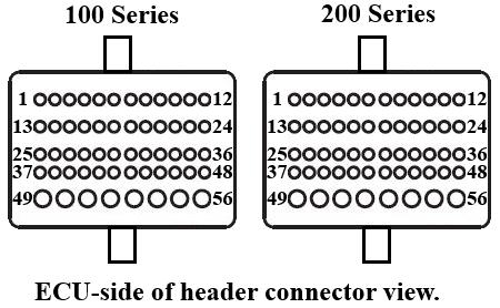
13 205 Model Brake Light Control 3 PINOUTS Infinity-8H Powersports, P/N Infinity Pin Hardware Reference Polaris RZR XP Function Polaris RZR XP Pin Destination Hardware Specification Notes C- LowsideSwitch_4 AWD Hub Control C2-246 Lowside switch,.7a max, NO internal f ly back diode. 2v pullup. C-2 LowsideSwitch_5 Chassis Relay Control C2-40 Lowside switch, 6A max with internal f ly back diode. Inductiv e load should Conf igured in Base Session f or chassis relay control. Not user adjustable. NOT hav e f ull time power. 2v pullup. C-3 Injector 7 For use with high impedance (05ohms) injectors only,.7a max. Av ailable. C-4 Injector 8 For use with high impedance (05ohms) injectors only,.7a max. Av ailable. C-5 UEGO Heat UEGO Heat C5-4 C-6 UEGO IA UEGO IA C5-6 C-7 UEGO IP UEGO IP C5- Bosch UEGO controller Terminated at 6-pin Lambda connector f or connecting a UEGO wideband Bosch LSU4.2 sensor (AEM ). C-8 UEGO UN UEGO UN C5-2 C-9 UEGO VM UEGO VM C5-5 Permanent Power Fly ing Lead Dedicated power management CPU Full time battery power. MUST be powered bef ore the ignition switch input is triggered. C- Coil 4 25 ma max source current C-2 Coil 3 25 ma max source current C-3 Coil 2 Coil 2 C ma max source current 0-5V Falling edge fire. DO NOT connect directly to coil primary. Connects to included AEM 3-Channel Ignitior. C-4 Coil Coil C ma max source current 0-5V Falling edge fire. DO NOT connect directly to coil primary. Connects to included AEM 3-Channel Ignitior. C-5 Coil 6 25 ma max source current Not used 25 ma max source current Not used Dif f erential Variable Reluctance Zero Cross Detection See Setup Wizard page 'Cam/Crank' for options. Dif f erential Variable Reluctance Zero Cross Detection Lowside switch,.7a max, NO internal f ly back diode. No pullup. May be adjusted under Coolant Fan options in Setup Wizard. C-0 Batt Perm Power C-6 Coil 5 Crank Position Sensor VR+ Crank Position Sensor VR+ C2-23 Crank Position C-8 Sensor VR- Crank Position Sensor VR- C2-20 C-7 C-9 Cam Position Sensor VR- C-20 Cam Position Sensor VR+ C-2 LowsideSwitch_2 Cooling Fan Relay C2-4 C-22 LowsideSwitch_3 SY NC Signal C-26 Conf igured in Base Session f or AWD Hub control. Not user adjustable. Lowside switch, 6A max with internal f ly back diode. Inductiv e load should ECU-generated SY NC signal. See "Sequential" section of Setup Wizard f or details. NOT hav e f ull time power. No pullup. C-23 AGND Sensor Ground C3-A, C2-04, Dedicated analog ground C2-05, C2-06 Sensor ground f or 0-5v analog inputs. C-24 AGND Sensor Ground C2-03, C2-204, Dedicated analog ground C7- Sensor ground f or 0-5v analog inputs. C-25 Crank Position Sensor Hall 0K pullup to 2V. Will work with ground or f loating switches. Frequency input only.
14 4 P/N SY NC Input C-22 0K pullup to 2V. Will work with ground or f loating switches. Frequency input only. See Setup Wizard Cam/Crank page f or options. C-27 Digital_In_2 AWD Request Signal C2-20 0K pullup to 2V. Will work with ground or f loating switches. Frequency input only. Conf igured in Base Session f or AWD Request Signal. Not user adjustable. C-28 Digital_In_3 Spare Frequency Input C7-4 0K pullup to 2V. Will work with ground or f loating switches. Frequency input only. Av ailable f requency input. Can be used f or Flex Fuel, Turbo Speed, or other. See Setup Wizard to conf igure input. C-29 Digital_In_4 Vehicle Speed Input C K pullup to 2V. Will work with ground or f loating switches. Frequency input only. Conf igured in Base Session f or v ehicle speed.may be adjusted under Vehicle Speed Input options in Setup Wizard. C-30 Digital_In_5 Brake Switch C2-35 0K pullup to 2V. Will work with ground or f loating switches. Switch input only. Conf igured in base session f or Brake Switch input. C-3 Coil 7 25 ma max source current C-32 Coil 8 25 ma max source current Ground C2-247 Power ground Power ground. Four pin DTM connector in AEM adapter harness. Contact AEM f or additional inf ormation. C-26 Cam Position Sensor Hall C-33 Power Ground C-34 CAN A- AEMNet CAN- Dedicated high speed CAN transceiv er C-35 CAN A+ AEMNet CAN + Dedicated high speed CAN transceiv er Four pin DTM connector in AEM adapter harness. Contact AEM f or additional inf ormation. C-36 CAN B- Chassis CAN- C2-44 Dedicated high speed CAN transceiv er Conf igured f or OEM dash display. Not user adjustable. C-37 CAN B+ Chassis CAN+ C2-32 Dedicated high speed CAN transceiv er Conf igured f or OEM dash display. Not user adjustable. C-38 Temp Coolant Temp Sensor C k pullup to 5v See Setup Wizard Coolant Temperature page f or options. C-39 Temp 2 Air Temp Sensor C k pullup to 5v See Setup Wizard Air Temperature page f or options. C-40 Temp 3 Spare Temp Input C k pullup to 5v Av ailable temperature input. Can be used f or Oil Temperature input or other. See Setup Wizard Input Function Assignments. C-4 LowsideSwitch_0 Fuel Pump C2-42 C-42 LowsideSwitch_ Spare Lowside Output C7- Ground C2-54 C-44 Knock Sensor C-45 Knock Sensor 2 C-43 Power Ground C-46 Power Ground Lowside switch, 4A max with internal Base session conf igured to driv e boost control solenoid. f ly back diode. Inductiv e load should May be reassigned in Setup Wizard Output Function NOT hav e f ull time power. No Assignments. pullup. Power ground Power ground. Dedicated knock signal processor Av ailable. See Setup Wizard Knock Setup page f or options. Dedicated knock signal processor Av ailable. See Setup Wizard Knock Setup page f or options. C2-53, C7-2 Power ground Power ground. Ground out to main relay C A max ground sink f or external relay control Will activ ate at key on and at key of f according to the conf iguration settings. Ignition Switch C2-6 0k pulldown Full time battery power must be av ailable at C-0 bef ore this input is triggered. C-49 +5V_Out +5V Sensor Power C2-25, C2-37 Regulated, f used +5V supply f or sensor power Analog sensor power. C-50 +5V_Out +5V Sensor Power C3-B, C7-9, C2- Regulated, f used +5V supply f or 20, C2-223 sensor power Analog sensor power. C-47 Main Relay Control Ground Lowside switch, 4A max, NO internal Switched ground. Will prime f or 2 seconds at key on f ly back diode. No pullup. and activ ate if RPM > 0. C-48 Ign Switch C-5 Analog_In_7 Throttle Position A C bit A/D, 00K pullup to 5V Conf igured f or TPSA input f rom OEM throttle body. C-52 Analog_In_8 MAP Sensor C3-C 2 bit A/D, 00K pullup to 5V See Setup Wizard Basic Sensors page f or options. C-53 Analog_In_9 Fuel Sender Signal C2-2 2 bit A/D, 00K pullup to 5V Conf igured f or OEM f uel lev el. Not user adjustable.
15 PINOUTS C-54 VR+_In_2 C-55 VR-_In_2 C-56 VR-_In_3 C-57 VR+_In_3 C-58 HighsideSwitch_0 Brake Lights Dif f erential Variable Reluctance Zero Cross Detection Dif f erential Variable Reluctance Zero Cross Detection C2-3, C A max, High Side Solid State See Notes Relay Brake light control, additional wiring required. C-59 Stepper_B Automotiv e, Programmable Stepper Driv er, up to 28V and ±.4A C-60 Stepper_2B Automotiv e, Programmable Stepper Driv er, up to 28V and ±.4A C-6 DBW Motor- DBW (-) C A max Throttle Control Hbridge Driv e Conf igured f or OEM DBW thottle body motor. C-62 DBW Motor+ DBW (+) C A max Throttle Control Hbridge Driv e Conf igured f or OEM DBW thottle body motor. C-63 +2v +2v C2-55, C7-0 2v power f rom main relay 5 2v power f rom main relay. C-64 Injector 6 For use with high impedance (05ohms) injectors only,.7a max. C-65 Injector 5 For use with high impedance (05ohms) injectors only,.7a max. C-66 Injector 4 For use with high impedance (05ohms) injectors only,.7a max. C-67 Power Ground Power ground Power ground. +2v C2-56, C5-3 2v power f rom main relay 2v power f rom main relay. C-69 Analog_In_9 APP2 Signal C2-2 bit A/D, 00K pullup to 5V Conf igured f or OEM DBW accelerator pedal position (APP) sensor. C-70 Analog_In_8 APP Signal C2-2 2 bit A/D, 00K pullup to 5V Conf igured f or OEM DBW accelerator pedal position (APP) sensor. C-7 Analog_In_6 Throttle Position B C bit A/D, 00K pullup to 5V Conf igured f or TPSB input f rom OEM throttle body. C-72 Flash Enable Flash Enable Flash Enable Connector 0k pulldown Two pin connector in AEM adapter harness. Use only to f orce EMS into f lash mode if normal f irmware update procedure does not work. C-73 Analog_In_3 Spare Analog Input C7-8 2 bit A/D, 00K pullup to 5V Can be used as Oil Pressure, Mode Switch, 3-Step or other analog input. See Input Function Assignments in Setup Wizard. C-74 Analog_In_ Cam Gen Signal C bit A/D, 00K pullup to 5V Analog input f or ECU-generated SY NC signal. See "Sequential" section of Setup Wizard f or details. C-75 Analog_In_0 Trans Position Signal C-75 2 bit A/D, 00K pullup to 5V Conf igured f or OEM transmission position. Not user adjustable. C-76 Injector 3 For use with high impedance (05ohms) injectors only,.7a max. C-77 Injector 2 Injector 2 C2-244 For use with high impedance (05ohms) injectors only,.7a max. Injector 2. C-78 Injector Injector C2-243 For use with high impedance (05ohms) injectors only,.7a max. Injector. C-79 Stepper_2A Automotiv e, Programmable Stepper Driv er, up to 28V and ±.4A C-80 Stepper_A Automotiv e, Programmable Stepper Driv er, up to 28V and ±.4A C-68 +2v

16 6 P/N 30-38
17 PINOUTS C3 C4 MAP 7 COIL Pin Dest. Pin Default Pin Function Pin Dest. Pin Default Pin Function C-52 MAP Signal 2 C-50 +5V 2 3 C-23 Sensor Ground 3 C2-256 Harness Coil 2 4 C2-250 Power Ground 5 C-3 ECU Coil 2 6 C2-254 Harness Coil 7 C-4 ECU Coil C5 LAMBDA Pin Dest. Pin C-8 Default Pin Function C6 Pin Dest. Pin Default Pin Function A C-0, F +2V Perm Power B C-72 Flash Enable UEGO Control 2 C-6 3 C-68, C256 4 C-5 5 C-9 6 C-7 +2V UEGO Control FLASH
18 8 P/N C7 AUX F BATTERY (+) Pin Dest. Pin Default Pin Function Pin Dest. Pin Default Pin Function C-42 Lowside C-0 +2V Perm Power 2 3 C-25 Digital 0 4 C-28 Digital C-40 AnalogTemperature3 7 8 C-73 Analog 3 9 C-50 +5V Ref 0 C-63 +2V C-24 Sensor Ground 2 C-46 Power Ground 2 MONTH LIMITED WARRANTY Advanced Engine Management Inc. warrants to the consumer that all AEM High Performance products will be free from defects in material and workmanship for a period of twelve (2) months from date of the original purchase. Products that fail within this 2-month warranty period will be repaired or replaced at AEM s option, when determined by AEM that the product failed due to defects in material or workmanship. This warranty is limited to the repair or replacement of the AEM part. In no event shall this warranty exceed the original purchase price of the AEM part nor shall AEM be responsible for special, incidental or consequential damages or cost incurred due to the failure of this product. Warranty claims to AEM must be transportation prepaid and accompanied with dated proof of purchase. This warranty applies only to the original purchaser of product and is non-transferable. All implied warranties shall be limited in duration to the said 2-month warranty period. Improper use or installation, accident, abuse, unauthorized repairs or alterations voids this warranty. AEM disclaims any liability for consequential damages due to breach of any written or implied warranty on all products manufactured by AEM. Warranty returns will only be accepted by AEM when accompanied by a valid Return Merchandise Authorization (RMA) number. Product must be received by AEM within 30 days of the date the RMA is issued. UEGO oxygen sensors are considered wear items and are not covered under warranty. Please note that before AEM can issue an RMA for any electronic product, it is first necessary for the installer or end user to contact the EMS tech line at to discuss the problem. Most issues can be resolved over the phone. Under no circumstances should a system be returned or a RMA requested before the above process transpires. AEM will not be responsible for electronic products that are installed incorrectly, installed in a non-approved application, misused, or tampered with. Any AEM electronics product can be returned for repair if it is out of the warranty period. There is a minimum charge of $50.00 for inspection and diagnosis of AEM electronic parts. Parts used in the repair of AEM electronic components will be extra. AEM will provide an estimate of repairs and receive written or electronic authorization before repairs are made to the product.
P/N Nissan Silvia SR20DET AEM Infinity PnP Harness STOP! THIS PRODUCT HAS LEGAL RESTRICTIONS. READ THIS BEFORE INSTALLING/USING!
 Instruction Manual 1994-1996 Nissan Silvia SR20DET AEM Infinity PnP Harness STOP! THIS PRODUCT HAS LEGAL RESTRICTIONS. READ THIS BEFORE INSTALLING/USING! THIS PRODUCT MAY BE USED SOLELY ON VEHICLES USED
P/N Polaris RZR XP Turbo AEM Infinity Plug and Play Harness STOP!
 Instruction Manual 206 Polaris RZR XP Turbo AEM Infinity Plug and Play Harness STOP! THIS PRODUCT HAS LEGAL RESTRICTIONS. READ THIS BEFORE INSTALLING/USING! THIS PRODUCT MAY BE USED SOLELY ON VEHICLES
P/N Toyota Supra MKIV Twin Turbo 2JZ-GTE AEM Infinity PnP Harness STOP!
 Instruction Manual 1993-1998 Toyota Supra MKIV Twin Turbo 2JZ-GTE AEM Infinity PnP Harness STOP! THIS PRODUCT HAS LEGAL RESTRICTIONS. READ THIS BEFORE INSTALLING/USING! THIS PRODUCT MAY BE USED SOLELY
PnP ADAPTER HARNESS. Instruction Manual VW 1.8T AWP INFINITY-6/8H*
 PnP ADAPTER HARNESS Instruction Manual 30-3903 2002-2005 VW 1.8T AWP INFINITY-6/8H* 2 3903-MKIV 1.8T Overview The 30-3903 AEM Infinity Adapter kit was designed for 2002-2005 Volkswagen 1.8T Golf/Jetta/GTI
Instruction Manual Mitsubishi EVO 8 INFINITY-6/8H* PnP ADAPTER HARNESS
 Instruction Manual 30-3511 2003-2005 Mitsubishi EVO 8 INFINITY-6/8H* PnP ADAPTER HARNESS 2 3511 - Mitsubishi EVO 8 Overview The 30-3511 AEM Infinity Adapter Kit was designed for the 2003-2005 Mitsubishi
Mitsubishi EVO 8 INFINITY-6/8H* PnP ADAPTER HARNESS STOP! THIS PRODUCT HAS LEGAL RESTRICTIONS. READ THIS BEFORE INSTALLING/USING!
 Instruction Manual 30-3511 2003-2005 Mitsubishi EVO 8 INFINITY-6/8H* PnP ADAPTER HARNESS STOP! THIS PRODUCT HAS LEGAL RESTRICTIONS. READ THIS BEFORE INSTALLING/USING! THIS PRODUCT MAY BE USED SOLELY ON
Instruction Manual. P/N Suzuki GSXR1300 Hayabusa 6 Speed Plug & Play Adapter Harness
 Instruction Manual P/N 30-3550 2002-2007 Suzuki GSXR1300 Hayabusa 6 Speed Plug & Play Adapter Harness OVERVIEW The 30-3550 AEM Infinity Adapter Kit was designed for the 2002 2007 Suzuki GSXR1300 Hayabusa.
Instruction Manual. P/N Honda S2000 Infinity-6 and Infinity-8h* Plug & Play Adapter Harness
 Instruction Manual 2000 2005 Honda S2000-6 and -8h* Plug & Play Adapter Harness 2 OVERVIEW The 30-3508 AEM Adapter Kit is designed for the 2000 2005 Honda S2000. These models include all 2.0L (AP1) engines
Core Harness System Crank/Cam Adapter Harness FAST Dual Sync Distrubutor 35" STOP!
 Instruction Manual 30-3805-20 Core Harness System Crank/Cam Adapter Harness FAST Dual Sync Distrubutor 35" STOP! THIS PRODUCT HAS LEGAL RESTRICTIONS. READ THIS BEFORE INSTALLING/USING! THIS PRODUCT MAY
Infinity-8/10&812 Mini Harness User Manual /03
 Infinity-8/10&812 Mini Harness User Manual 30-3702/03 THIS PRODUCT IS LEGAL IN CALIFORNIA FOR RACING VEHICLES ONLY AND SHOULD NEVER BE USED ON PUBLIC HIGHWAYS. AEM Performance Electronics AEM Performance
GM Stepper Idle Adapter User Manual
 GM Stepper Idle Adapter User Manual 30-3805-07 THIS PRODUCT IS LEGAL IN CALIFORNIA FOR RACING VEHICLES ONLY AND SHOULD NEVER BE USED ON PUBLIC HIGHWAYS. AEM Performance Electronics AEM Performance Electronics,
GM Throttle Body Adapter Harness User Manual
 GM Throttle Body Adapter Harness User Manual 30-3809-01 THIS PRODUCT IS LEGAL IN CALIFORNIA FOR RACING VEHICLES ONLY AND SHOULD NEVER BE USED ON PUBLIC HIGHWAYS. AEM Performance Electronics AEM Performance
Infinity Supported Application Honda B/D/H Series STOP! THIS PRODUCT HAS LEGAL RESTRICTIONS. READ THIS BEFORE INSTALLING/USING!
 Instruction Manual Supported Application 1992 2000 B/D/H Series STOP! THIS PRODUCT HAS LEGAL RESTRICTIONS. READ THIS BEFORE INSTALLING/USING! THIS PRODUCT MAY BE USED SOLELY ON VEHICLES USED IN SANCTIONED
Ford EV6 Injector Adapter Harness User Manual
 Ford EV6 Injector Adapter Harness User Manual 30-3805- THIS PRODUCT IS LEGAL IN CALIFORNIA FOR RACING VEHICLES ONLY AND SHOULD NEVER BE USED ON PUBLIC HIGHWAYS. AEM Performance Electronics AEM Performance
Mini Flying Lead Harness for Infinity-6/8h STOP! THIS PRODUCT HAS LEGAL RESTRICTIONS. READ THIS BEFORE INSTALLING/USING!
 Instruction Manual 30-3706 Mini Flying Lead Harness for Infinity-6/8h STOP! THIS PRODUCT HAS LEGAL RESTRICTIONS. READ THIS BEFORE INSTALLING/USING! THIS PRODUCT MAY BE USED SOLELY ON VEHICLES USED IN SANCTIONED
P/N Toyota Supra MKIV Twin Turbo Manual Transmission Plug & Play Adapter Harness STOP!
 Instruction Manual Manual Transmission Plug & Play Adapter Harness STOP! THIS PRODUCT HAS LEGAL RESTRICTIONS. READ THIS BEFORE INSTALLING/USING! THIS PRODUCT MAY BE USED SOLELY ON VEHICLES USED IN SANCTIONED
P/N Ford Coyote 4V 5.0L V8 AEM Infinity Coyote Engine Harness Adapter STOP!
 Instruction Manual Ford Coyote 4V 5.0L V8 AEM Coyote Engine Harness Adapter STOP! THIS PRODUCT HAS LEGAL RESTRICTIONS. READ THIS BEFORE INSTALLING/USING! THIS PRODUCT MAY BE USED SOLELY ON VEHICLES USED
Multi-Input Water/Methanol Injection Harness
 Multi-Input Water/Methanol Injection Harness 30-3324 WARNING: Improper installation and/or adjustment of this product can result in major engine/vehicle damage! Use of this injection system requires proper
Part Number AEM 4-CH WIDEBAND UEGO CONTROLLER
 Part Number 30-2340 AEM 4-CH WIDEBAND UEGO CONTROLLER FIGURE 1. WIRING DIAGRAM AEM Performance Electronics 2205 126 th Street Unit A, Hawthorne, CA. 90250 Phone: (310) 484-2322 Fax: (310) 484-0152 http://www.aemelectronics.com
P/N Water/Methanol Injection V2 Nozzle Kit Includes T-Fitting, Hose, 250cc, 500cc, & 1000cc Jets STOP!
 Instruction Manual P/N 30-3312 Water/Methanol Injection V2 Nozzle Kit Includes T-Fitting, Hose, 250cc, 500cc, & 1000cc Jets STOP! THIS PRODUCT HAS LEGAL RESTRICTIONS. READ THIS BEFORE INSTALLING/USING!
Plug & Play Adapter Harness. Instruction Manual. P/N Ford Coyote 5.0L V8 with Ford Racin Controls Pack
 Plug & Play Adapter Harness Instruction Manual Coyote 5.0L V8 with Racin Controls Pack 2 OVERVIEW The 30-3812 AEM Infinity Adapter Kit was designed to interface the Coyote 5.0L wiring harness and the Control
P/N Ford Coyote 5.0L V8 with Ford Racing Controls Pack Plug & Play Adapter Harness STOP!
 Instruction Manual Coyote 5.0L V8 with Controls Pack Plug & Play Adapter Harness STOP! THIS PRODUCT HAS LEGAL RESTRICTIONS. READ THIS BEFORE INSTALLING/USING! THIS PRODUCT MAY BE USED SOLELY ON VEHICLES
Internal MAP Water/Methanol Injection Controller ,
 Internal MAP Water/Methanol Injection Controller 30-3304, 30-3306 WARNING: Improper installation and/or adjustment of this product can result in major engine/vehicle damage! Use of this injection system
Flex Fuel Sensor Kit (Barbed) Flex Fuel Sensor Kit (-6AN)
 Flex Fuel Sensor Kit (-6AN)") 0-00 Flex Fuel Sensor Kit (Barbed) 0-0 Flex Fuel Sensor Kit (-6AN) THIS PRODUCT IS LEGAL IN CALIFORNIA FOR RACING VEHICLES ONLY AND SHOULD NEVER BE USED ON PUBLIC HIGHWAYS. AEM Performance Electronics
0-00 Flex Fuel Sensor Kit (Barbed) 0-0 Flex Fuel Sensor Kit (-6AN) THIS PRODUCT IS LEGAL IN CALIFORNIA FOR RACING VEHICLES ONLY AND SHOULD NEVER BE USED ON PUBLIC HIGHWAYS. AEM Performance Electronics
P/N Water/Methanol Injection V2 1-Gallon Tank With Conductive Fluid Level Sensor* STOP!
 Instruction Manual P/N 30-3325 Water/Methanol Injection V2 1-Gallon Tank With Conductive Fluid Level Sensor* STOP! THIS PRODUCT HAS LEGAL RESTRICTIONS. READ THIS BEFORE INSTALLING/USING! THIS PRODUCT MAY
Polaris RZR XPT CD-7 Plug & Play Harness Kit
 30-2216 Polaris RZR XPT CD-7 Plug & Play Harness Kit AEM Performance Electronics AEM Performance Electronics, 2205 126th Street Unit A, Hawthorne, CA 90250 Phone: (310) 484-2322 Fax: (310) 484-0152 http://www.aemelectronics.com
P/N Water/Methanol Injection V2 Standard Controller Internal MAP with 35psi Max STOP!
 Instruction Manual P/N 30-3304 Water/Methanol Injection V2 Standard Controller Internal MAP with 35psi Max STOP! THIS PRODUCT HAS LEGAL RESTRICTIONS. READ THIS BEFORE INSTALLING/USING! THIS PRODUCT MAY
Installation Instructions for: DT2-AF2 Dual Channel & DT2-AF1 Single Channel Wide Band O2 Sensor Controller for A/F (Lambda) Measurement
 Measurement") Installation Instructions for: DT2-AF2 Dual Channel & DT2-AF1 Single Channel Wide Band O2 Sensor Controller for A/F (Lambda) Measurement WARNING: This installation is not for the electrically or mechanically
Installation Instructions for: DT2-AF2 Dual Channel & DT2-AF1 Single Channel Wide Band O2 Sensor Controller for A/F (Lambda) Measurement WARNING: This installation is not for the electrically or mechanically
10 Ch Peak & Hold Injector Driver PN
 Installation Instructions 10 Ch Peak & Hold Injector Driver PN 30-2710 WARNING: installation is not for the electrically challenged! Use this product with extreme caution! If you are uncomfortable with
Part Number Analog Style 15 PSI Fuel/Boost Pressure Gauge. NOTE: Faceplate Configuration Instructions Included on Separate Sheet
 Part Number 30-5144 Analog Style 15 PSI Fuel/Boost Pressure Gauge NOTE: Faceplate Configuration Instructions Included on Separate Sheet AEM Oil/Fuel Pressure Gauge Parts 1 x 35-5144 Pressure Gauge Assembly
Installation Instructions for: Channel Thermocouple Amplifier
 Installation Instructions for: 30-2204 4 Channel Thermocouple Amplifier WARNING: This installation is not fo r the electrically or mechanically challenged! Use this sensor with EXTREME caution! If you
Part Number Analog EGT Gauge
 Part Number 30-5131 Analog EGT Gauge Figure 1. Wiring Schematic AEM EGT Gauge Parts 1 x 35-5131(B/W) EGT Gauge Assembly 1 x 30-2065 EGT Sensor Thermocouple w/mount 1 x 35-4302 Install Kit (6 Butt Connectors)
P/N X-SERIES GAUGE VOLTAGE 8 TO 18V
 Instruction Manual P/N 30-0303 X-SERIES GAUGE VOLTAGE 8 TO 8V STOP! - READ THIS BEFORE INSTALL OR USE! WARNING: THIS INSTALLATION REQUIRES WELDING AND INTEGRATION INTO A VEHICLE'S ELECTRICAL SYSTEM. DAMAGE
Installation Instructions for: EMS P/N Acura NSX
 Installation Instructions for: EMS P/N 30-1042 1991-94 Acura NSX! WARNING: This installation is not for the tuning novice nor the PC illiterate! Use this system with EXTREME caution! The AEM EMS System
Universal 8 Infinity Supported Application STOP! THIS PRODUCT HAS LEGAL RESTRICTIONS. READ THIS BEFORE INSTALLING/USING!
 Instruction Manual Universal 8 Infinity Supported Application STOP! THIS PRODUCT HAS LEGAL RESTRICTIONS. READ THIS BEFORE INSTALLING/USING! THIS PRODUCT MAY BE USED SOLELY ON VEHICLES USED IN SANCTIONED
Installation Instructions for: EMS P/N Ford Mustang 5.0L
 Installation Instructions for: EMS P/N 30-1401 1994-95 Ford Mustang 5.0L! WARNING: This installation is not for the tuning novice nor the PC illiterate! Use this system with EXTREME caution! The AEM EMS
ELITE 1000/1500 Dodge SRT QUICK START GUIDE HT
 E N G I N E M A N A G E M E N T S Y S T E M S ELITE 1000/1500 Dodge SRT4 03-05 QUICK START GUIDE HT-140940 LIMITED WARRANTY Lockin Pty Ltd trading as Haltech warrants the HaltechTM Programmable Fuel Injection
Installation Instructions for: EMS P/N Honda S2000
 Installation Instructions for: EMS P/N 30-6052 2000-2005 Honda S2000! WARNING: This installation is not for the tuning novice nor the PC illiterate! Use this system with EXTREME caution! The AEM EMS System
* NOTE: Legal in California only for racing vehicles which may never be used upon a highway
 Read and understand these instructions BEFORE attempting to install this product. Failure to follow installation instructions and not using the provided hardware may damage the intake tube, throttle body
Installation Instructions for: EMS P/N Toyota MR2 Turbo Toyota Celica All Trac
 Installation Instructions for: EMS P/N 30-1120 1991-1992 Toyota MR2 Turbo 1990-1992 Toyota Celica All Trac! WARNING: This installation is not for the tuning novice nor the PC illiterate! Use this system
Installation Instructions for: EMS P/N Ford Mustang 5.0L
 Installation Instructions for: EMS P/N 30-1400 1986-93 Ford Mustang 5.0L! WARNING: This installation is not for the tuning novice nor the PC illiterate! Use this system with EXTREME caution! The AEM EMS
Installation Instructions for: EMS P/N Eclipse Turbo, Talon Tsi, Laser RS Galant VR4
 Installation Instructions for: EMS P/N 30-6300 1990-1994 Eclipse Turbo, Talon Tsi, Laser RS Galant VR4! WARNING: This installation is not for the tuning novice nor the PC illiterate! Use this system with
Installation Instructions for / Universal Water/Methanol Injection Kit
 Installation Instructions for 30-3000 / 30-3001 Universal Water/Methanol Injection Kit WARNING: This installation is not for the electrically or mechanically challenged! Use this system with EXTREME caution!
Installation Instructions for: EMS P/N Silvia S13 SR20DET Nissan 180SX SR20DET
 Installation Instructions for: EMS P/N 30-6601 1991-1993 Silvia S13 SR20DET 1991-1995 Nissan 180SX SR20DET! WARNING: This installation is not for the tuning novice nor the PC illiterate! Use this system
Oil Pressure Display Gauges Part numbers: Analog Oil/Fuel SAE Pressure Gauge psi Analog Oil SAE Pressure Gauge.
 Oil Pressure Display Gauges Part numbers: 30-5133 - Analog Oil/Fuel SAE Pressure Gauge. 0-100psi 30-5135 - Analog Oil SAE Pressure Gauge. 0-150psi AEM's Analog style Oil Pressure Gauges feature quick response
Installation Instructions for AEM Serial Gauge
 Installation Instructions for 30-4300 AEM Serial Gauge WARNING: This installation is not for the electrically or mechanically challenged! Use this gauge with EXTREME caution! If you are! uncomfortable
Installation Instructions for: EMS P/N Toyota Supra
 Installation Instructions for: EMS P/N 30-1110 1987-1988 Toyota Supra! WARNING: This installation is not for the tuning novice nor the PC illiterate! Use this system with EXTREME caution! The AEM EMS System
E9X/E8X/E6X CHASIS VEHICLES (With N54 Motors)
") Installation Manual P/N 1-301-1706-01 (N54 Coil-Pack Conversion Kit) E9X/E8X/E6X CHASIS VEHICLES (With N54 Motors) Warning: This installation is not recommended for a novice or the new guy in the shop.
Installation Manual P/N 1-301-1706-01 (N54 Coil-Pack Conversion Kit) E9X/E8X/E6X CHASIS VEHICLES (With N54 Motors) Warning: This installation is not recommended for a novice or the new guy in the shop.
Installation Instructions for: EMS P/N Eclipse Turbo, Talon Tsi, Laser RS Galant VR4
 Installation Instructions for: EMS P/N 30-6300 1990-1994 Eclipse Turbo, Talon Tsi, Laser RS Galant VR4 Thank you for purchasing an AEM Engine Management System. The AEM Engine Management System (EMS) is
Installation Instructions for Gauge-Type UEGO Controller
 Installation Instructions for 30-4100 Gauge-Type UEGO Controller WARNING: This installation is not for the electrically or mechanically challenged! Use this sensor with EXTREME caution! If you are! uncomfortable
Installation Instructions for: EMS P/N Mitsubishi 3000GT VR Dodge Stealth TT
 Installation Instructions for: EMS P/N 30-6311 1991-97 Mitsubishi 3000GT VR4 1991-1997 Dodge Stealth TT! WARNING: This installation is not for the tuning novice nor the PC illiterate! Use this system with
Installation Instructions for: EMS P/N Toyota Supra
 Installation Instructions for: EMS P/N 30-1130 1989-1992 Toyota Supra! WARNING: This installation is not for the tuning novice nor the PC illiterate! Use this system with EXTREME caution! The AEM EMS System
P/N GPS MODULE
 Instruction Manual P/N 30-2207 GPS MODULE STOP! - READ THIS BEFORE INSTALL OR USE! WARNING: THIS INSTALLATION MAY REQUIRE WELDING OR INTEGRATION INTO A VEHICLE'S ELECTRICAL SYSTEM. DAMAGE TO SENSITIVE
Installation Instructions for: EMS P/N Acura Integra Acura 2.3CL Honda Accord Honda Civic
 Installation Instructions for: EMS P/N 30-6050 00-01 Acura Integra 98-99 Acura 2.3CL 98-02 Honda Accord 99-00 Honda Civic! WARNING: This installation is not for the tuning novice nor the PC illiterate!
Equipped with AEM Dryflow Filter No Oil Required! INSTALLATION INSTRUCTIONS
 Equipped with AEM Dryflow Filter No Oil Required! INSTALLATION INSTRUCTIONS PART NUMBER: 21-448 2005 CHEVROLET Cavalier Ecotec L4-2.2L SEE * NOTE 2005 PONTIAC Sunfire L4-2.2L C.A.R.B. E.O. # D-392-28 2003-2004
Installation Instructions for: EMS P/N and U Honda S2000
 Installation Instructions for: EMS P/N 30-1052 and 30-1052U 00-04 Honda S2000! WARNING: This installation is not for the tuning novice nor the PC illiterate! Use this system with EXTREME caution! The AEM
Kit Part Number:
 Equipped with AEM DRYFLOW Filter No oil required! Kit Part Number: 21-8203 2003-2005 Dodge Ram 5.7L V8 CARB EO # D-392-28 2005 Dodge Powerwagon Hemi CARB EO # D-392-28 Brute Force Intake Systems that are
Installation Instructions for P/N HD Water Injection Kit with 5 Gallon Tank
 Installation Instructions for P/N 30-3111 HD Water Injection Kit with 5 Gallon Tank 2001-2010 6.6L Duramax Diesel Chevrolet Silverado HD: GMC Sierra HD; Chevrolet Kodiak ; GMC Topkick Hummer H-1 Alpha;
Instru ct ion Manual
 Instruction Manual 2 P/N 30-3510 OVERVIEW The 30-3510 AEM Infinity Adapter Kit was designed for the 2001 2006 BMW E46 M3 with manual transmission. This is a true standalone system that eliminates the use
Part Number cc/min Water/Methanol Injection Flow Gauge
 Part Number 30-5141 500 cc/min Water/Methanol Injection Flow Gauge Figure 1. Wiring Schematic This product is legal in California for racing vehicles only and should never be used on public highways. AEM
Installation Instructions for: EMS P/N Acura Integra Acura 2.3CL Honda Accord Honda Civic
 Installation Instructions for: EMS P/N 30-6050 00-01 Acura Integra 98-99 Acura 2.3CL 98-02 Honda Accord 99-00 Honda Civic Thank you for purchasing an AEM Engine Management System. The AEM Engine Management
P/N BMW E46 M3 Manual Transmission Plug & Play Adapter Harness STOP!
 Instruction Manual 2001 2006 BMW E46 M3 Manual Transmission Plug & Play Adapter Harness STOP! THIS PRODUCT HAS LEGAL RESTRICTIONS. READ THIS BEFORE INSTALLING/USING! THIS PRODUCT MAY BE USED SOLELY ON
advanced FLOW engineering Instruction Manual P/N: Make: Ford Model: F-150 Raptor Year: Engine: V6-3.
 advanced FLOW engineering Instruction Manual P/N: 77-83023 Make: Ford Model: F-150 Raptor Year: 2017-2018 Engine: V6-3.5L (tt) EcoBoost Please read the entire instruction manual before proceeding. Ensure
P/N CHANNEL CAN SENSOR MODULE
 Instruction Manual P/N 30-2226 6 CHANNEL CAN SENSOR MODULE STOP! - READ THIS BEFORE INSTALL OR USE! WARNING: THIS INSTALLATION MAY REQUIRE WELDING OR INTEGRATION INTO A VEHICLE'S ELECTRICAL SYSTEM. DAMAGE
25-30XBK HONDA ADJUSTABLE FUEL PRESSURE REGULATOR
 Read and understand these instructions BEFORE attempting to install this product. Do not smoke while working on the fuel system. Keep open flames or sparks away from your work area. Be sure to relieve
MaxxECU quickstart guide ( )
") Be a tuning mastermind. Like us. MaxxECU quickstart guide (2019-02-01) Online help! maxxecu.com/support Wiring diagrams Installation help Pinout Support maxxecu.com/support Legal disclaimer All performance
Be a tuning mastermind. Like us. MaxxECU quickstart guide (2019-02-01) Online help! maxxecu.com/support Wiring diagrams Installation help Pinout Support maxxecu.com/support Legal disclaimer All performance
This product is legal in California for racing vehicles only and should never be used on public highways.
 Installation Instructions for: EMS P/N 30-1602 and 30-1602U 96-99 Nissan 180SX SR20DET 97-98 Nissan Silvia S14 SR20DET 93-98 Nissan Silvia S14 SR20DET (Europe) 99-02 Nissan Silvia S15 SR20DET! WARNING:
Universal V8 Harness System User Manual STOP! THIS PRODUCT HAS LEGAL RESTRICTIONS. READ THIS BEFORE INSTALLING/USING!
 Instruction Manual 30-3809 Universal V8 Harness System User Manual STOP! THIS PRODUCT HAS LEGAL RESTRICTIONS. READ THIS BEFORE INSTALLING/USING! THIS PRODUCT MAY BE USED SOLELY ON VEHICLES USED IN SANCTIONED
INSTALLATION INSTRUCTIONS PART NUMBER
 Equipped with AEM Dryflow Filter No Oil Required! INSTALLATION INSTRUCTIONS PART NUMBER 21-750 2013-16 Audi A4 2.0T C.A.R.B. E.O. # D-670-23 2014-16 Audi A5 2.0T C.A.R.B. E.O. # D-670-23 ITEM NO. PART
INSTALLATION INSTRUCTIONS PART NUMBER:
 Equipped with AEM Dryflow Filter No Oil Required! INSTALLATION INSTRUCTIONS PART NUMBER: 22-482 2000-2003 MAZDA Miata L4-1.8L C.A.R.B. E.O. # D-392-28 * NOTE: Legal in California only for racing vehicles
PLATINUM Sport Haltech GM LS1 / LS6 Terminated Engine Harness (HT045650) QUICK START GUIDE
 QUICK START GUIDE") PLATINUM Sport 2000 Haltech GM LS1 / LS6 Terminated Engine Harness (HT045650) QUICK START GUIDE LIMITED WARRANTY Lockin Pty Ltd trading as Haltech warrants the Haltech TM Programmable Fuel Injection System
PLATINUM Sport 2000 Haltech GM LS1 / LS6 Terminated Engine Harness (HT045650) QUICK START GUIDE LIMITED WARRANTY Lockin Pty Ltd trading as Haltech warrants the Haltech TM Programmable Fuel Injection System
Installation Instructions for: EMS P/N Acura Integra Acura 2.3CL Honda Accord Honda Civic
 ! Installation Instructions for: EMS P/N 30-1010 00-01 Acura Integra 98-99 Acura 2.3CL 98-02 Honda Accord 99-00 Honda Civic WARNING: This installation is not for the tuning novice nor the PC illiterate!
Quick Start Guide. This is only a quick start guide. A full wiring and installation manual is included in PCLink.
 Quick Start Guide This is only a quick start guide. A full wiring and installation manual is included in PCLink. Installer I/O Table Wire Description Installer Connection Typical Application +14V Bat Full
advanced FLOW engineering Instruction Manual P/N:
 advanced FLOW engineering Instruction Manual P/N: 77-84010 Make: Chevrolet Model: Silverado HD Year: 2017-2018 Engine: V8-6.6L (td) Duramax (L5P) Make: GMC Model: Sierra HD Year: 2017-2018 Engine: V8-6.6L
VW/AUDI MK7 VEHICLES
 Installation Manual P/N 1-301-1708-01 (STAGE 2+ FUEL KIT) P/N 1-301-1708-02 (STAGE 3+ FUEL KIT) VW/AUDI MK7 VEHICLES Warning: This installation is not recommended for a novice or the new guy in the shop.
INSTALLATION INSTRUCTIONS
 Equipped with AEM Dryflow Filter No Oil Required! INSTALLATION INSTRUCTIONS PART NUMBER:21-8402 1999-2004 TOYOTA Tacoma V6-3.4L C.A.R.B. E.O. # D-670 1999-2002 TOYOTA 4Runner V6-3.4L C.A.R.B. E.O. # D-670
Equipped with AEM Dryflow Filter No Oil Required! INSTALLATION INSTRUCTIONS
 Equipped with AEM Dryflow Filter No Oil Required! INSTALLATION INSTRUCTIONS PART NUMBER: 21-9211 2003-2006 DODGE Ram 2500 Pickup L6-5.9L DSL C.A.R.B. E.O. # D-670 2003-2006 DODGE Ram 3500 Pickup L6-5.9L
INSTALLATION INSTRUCTIONS
 Equipped with AEM Dryflow Filter No Oil Required! INSTALLATION INSTRUCTIONS PART NUMBER: 24-6105 2002-2006 ACURA RSX - Excludes Type S L4-2.0L C.A.R.B. E.O. # D-670 * NOTE: Legal in California only for
Installation Instructions for NS No Sensor Gauge-Type UEGO Controller
 Installation Instructions for 30-4110NS No Sensor Gauge-Type UEGO Controller WARNING: This installation is not for the electrically or mechanically challenged! Use this sensor with EXTREME caution! If
advanced FLOW engineering Instruction Manual P/N: SCORCHER BLUE Bluetooth Power Module
 advanced FLOW engineering Instruction Manual P/N: 77-84009 SCORCHER BLUE Bluetooth Power Module Make: Chevrolet Model: Colorado Year: 2016-2019 Engine: I4-2.8L (td) Duramax (LWN) Make: GMC Model: Canyon
Equipped with AEM Dryflow Filter No Oil Required! INSTALLATION INSTRUCTIONS PART NUMBER DS BMW 335i 3.0L
 Equipped with AEM Dryflow Filter No Oil Required! INSTALLATION INSTRUCTIONS PART NUMBER 21-754DS 2012-2015 BMW 335i 3.0L 1 ITEM NO. PART NUMBER DESCRIPTION QTY. 1 21-2057DK AIR FILTER 1 2 9-0442 TUBE;
Installation Instructions for: EMS P/N Dodge Viper V-10
 Installation Instructions for: EMS P/N 30-1500 1996-02 Dodge Viper V-10! WARNING: This installation is not for the tuning novice nor the PC illiterate! Use this system with EXTREME caution! The AEM EMS
INSTALLATION INSTRUCTIONS THERMOCOUPLE EXPANSION MODULE
 INSTALLATION INSTRUCTIONS THERMOCOUPLE EXPANSION MODULE 2650-1846-77 Rev. B Details: Temperature Rating: -40 C to 85 C/-40 F to 185 F Vibration Specification: 20 g continuous, 50 g shock Inputs: o 4 EGT
INSTALLATION INSTRUCTIONS PART NUMBER:
 Equipped with AEM Dryflow Filter No Oil Required! INSTALLATION INSTRUCTIONS PART NUMBER: 21-447 1998-2001 CHEVROLET Cavalier L4-2.2L Manual trans. requires 20-455 C.A.R.B. E.O. # D-670 2000-2002 PONTIAC
2 Wire PW Idle Adapter User Manual
 2 Wire PW Idle Adapter User Manual 30-3805-08 2 AEM Infinity Harness Manuals Introduction Several universal wiring harness options are available for Infinity products. They range in complexity from simple
INSTALLATION INSTRUCTIONS PART NUMBER:
 Equipped with AEM Dryflow Filter No Oil Required! INSTALLATION INSTRUCTIONS PART NUMBER: 21-641 2006 MAZDA Mazdaspeed 6 L4-2.3L C.A.R.B. E.O. # D-670-2 * NOTE: Legal in California only for racing vehicles
INSTALLATION INSTRUCTIONS
 Equipped with AEM Dryflow Filter No Oil Required! INSTALLATION INSTRUCTIONS PART NUMBER 21-823DS (GUN METAL GRAY FINISH) 2014-17 INFINITI Q70 3.7L 1 ITEM NO. PART NUMBER DESCRIPTION QTY. 1 21-202DOSK AIR
INSTALLATION INSTRUCTIONS
 Equipped with AEM Dryflow Filter No Oil Required! INSTALLATION INSTRUCTIONS PART NUMBER: 21-510B (Blue Finish) 21-510C (Gun Metal Grey Finish) 21-510P (Vacuum Metalized Chrome-VMC) 21-510R (Red Finish)
1. Index. LS Wiring Harness. 2. Presentation Warnings and Warranty Terms Overview Labels...7
 OWNER S MANUAL 1. Index 2. Presentation...4 3. Warnings and Warranty Terms...5 4. Overview...6 5. Labels...7 6. Diagrams...7 6.1 FT500/FT500 Aux - Inputs/outputs...7 6.2 Nano WB O2 #1...8 6.3 Nano WB
Equipped with AEM Dryflow Filter No Oil Required! INSTALLATION INSTRUCTIONS PART NUMBER:
 Equipped with AEM Dryflow Filter No Oil Required! INSTALLATION INSTRUCTIONS PART NUMBER: 21-630 1991-1992 SATURN SC L4-1.9L Manual Trans. C.A.R.B. E.O. # D-670-6 1993-1994 SATURN SW2 L4-1.9L Manual Trans.
INSTALLATION INSTRUCTIONS
 Equipped with AEM Dryflow Filter No Oil Required! INSTALLATION INSTRUCTIONS PART NUMBER: 24-6005 1992-2001 HONDA Prelude L4-2.2L C.A.R.B. E.O. # D-670 1992-1996 HONDA Prelude L4-2.3L C.A.R.B. E.O. # D-670
INSTALLATION INSTRUCTIONS PART NUMBER C (Gun Metal Gray Finish)
") Equipped with AEM Dryflow Filter No Oil Required! INSTALLATION INSTRUCTIONS PART NUMBER 21-765C (Gun Metal Gray Finish) 2014-16 MAZDA 3 2.0L *Manual Transmission Only 1 ITEM NO. PART NUMBER DESCRIPTION
Equipped with AEM Dryflow Filter No Oil Required! INSTALLATION INSTRUCTIONS PART NUMBER 21-765C (Gun Metal Gray Finish) 2014-16 MAZDA 3 2.0L *Manual Transmission Only 1 ITEM NO. PART NUMBER DESCRIPTION
advanced FLOW engineering Instruction Manual P/N: & Make: BMW Model: 335i E90/92/93 Year: Engine: L6-3.
 advanced FLOW engineering Instruction Manual P/N: 77-46301 & 77-46304 Make: BMW Model: 335i E90/92/93 Year: 2011-2013 Engine: L6-3.0L (t) N55 Also Fits: BMW 135i (E8x)/ 535i (F10)/ X5 35i (E70)/ X6 35i
INSTALLATION INSTRUCTIONS
 Equipped with AEM Dryflow Filter No Oil Required! INSTALLATION INSTRUCTIONS PART NUMBER:22-489 2004 MAZDA Miata Mazdaspeed L4-1.8L C.A.R.B. E.O. # D-670 PARTS LIST Description Qty. Part Number Element
INSTALLATION INSTRUCTIONS
 Equipped with AEM Dryflow Filter No Oil Required! INSTALLATION INSTRUCTIONS PART NUMBER: 21-685 2006-2011 HONDA Civic SI L4-2.0L SEE * NOTE * NOTE: Legal in California only for racing vehicles which may
INSTALLATION INSTRUCTIONS PART NUMBER:
 Equipped with AEM Dryflow Filter No Oil Required! INSTALLATION INSTRUCTIONS PART NUMBER: 22-474 2006-2007 SUBARU Impreza WRX H4-2.5L C.A.R.B. E.O. # D-670-6 2004-2007 SUBARU Impreza WRX STi H4-2.5L C.A.R.B.
Equipped with AEM Dryflow Filter No Oil Required!
 Equipped with AEM Dryflow Filter No Oil Required! INSTALLATION INSTRUCTIONS PART NUMBER: 21-491B (Blue Finish) 21-491C (Gun Metal Grey Finish) 21-491P (Vacuum Metalized Chrome-VMC) 21-491R (Red Finish)
PLATINUM. Sport Haltech 13B Terminated Engine Harness QUICK START GUIDE
 PLATINUM Sport 1000 Haltech 13B Terminated Engine Harness QUICK START GUIDE HALTECH HEAD OFFICE: PH: +612 9729 0999 FAX: +612 9729 0900 EMAIL: sales@haltech.com HALTECH US OFFICE: EMAIL: usa@haltech.com
COLD AIR INTAKE SYSTEM
 COLD AIR INTAKE SYSTEM Installation Instructions for: Part Number 21-491 2005-2008 Mazda 6i 2.3L NON-PZEV Do not install a bypass valve on this intake system! ADVANCED ENGINE MANAGEMENT INC. 2205 126 TH
INSTRUCTIONS PART NUMBER:
 Equipped with AEM Dryflow Filter No Oil Required! INSTALLATION INSTRUCTIONS PART NUMBER: 21-477 2006-2007 SUBARU Impreza WRX H4 2.5L Turbo C.A.R.B. E.O. # D-670-15 2004-2007 SUBARU Impreza WRX STi H4 2.5L