ThermoLite 36W Solar Panel Installation Guide
|
|
|
- Stella Leonard
- 6 years ago
- Views:
Transcription
 4. Competitive Units (all models) 5.")
.")

1 ThermoLite 36W Solar Panel Installation Guide Install applications supported by this guide: 1. Heat King (all models) 2. SB Domestic Rail Container (DRC front skin mounted) 3. Precedent Domestic Rail Container (DRC front skin mounted) 4. Competitive Units (all models) 5. SB III (top mounted) General Installation Precautions and Specifications WARNING: Always wear safety glasses and protective gloves when working with batteries. IMPORTANT: The solar panel, application surface and air temperature must all be above 45 F (1.3 C). For best results when applying the panel adhesive, ensure the surface is completely clean using Isopropal alcohol or appropriate de-greasers. Ensure all cleaning residue is removed and the surface is dry. The adhesive backing is very aggressive and is difficult to remove once installed. Always ensure the solar panel fuse (located on the terminal connection harness) is removed during installation and service. Locate the charge controller near the unit electrical connection to avoid voltage loss in the cable. Hardware Kit Guide TK IM (Rev. 2, 06/15) Copyright 2015 Thermo King Corp. Minneapolis, MN, USA
. 4.")


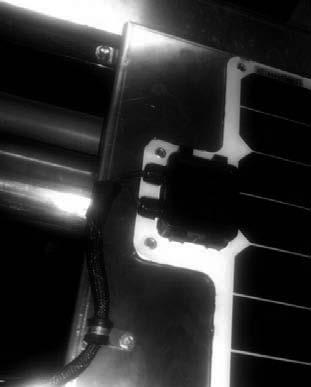
2 Heat King Unit Installation 1. Switch unit controls to the off position and disconnect the positive battery cable. 2. Temporarily remove the fuse from solar panel harness. 3. Ensure the top surface of the unit is clean and free of any dirt (Figure 1). 4. Peel back the top 4 inches of the backing paper and apply the top edge of the panel near the assembly bolts and the left side against the coolant cap cutout hole (Figures 2 and 3). The junction box should be facing toward the roadside of the unit. 5. With the panel properly positioned, remove the remainder of the backing paper and firmly press the panel down over the entire area. Repeat several times to ensure the entire panel is properly adhered to the sheetmetal skin. This is critical to prevent moisture between the surfaces. 6. Drill 5/32'' holes at all panel grommet holes. Secure panel with #10-14 x 1/2'' long thread forming screws (10 places). 7. Drill a 7/8 hole near the front roadside corner (Figure 4). To prevent drilling through overlapping sheetmetal (which will cause rust), it is advised to drill a pilot hole up from inside the unit. Drilling through the insulation is acceptable (Figures 4 and 5). Figure 1 Figure 2 Figure 3 8. Cut a slit in the provided rubber grommet (330324) and place around the harness exiting the panel. Place the connector through the hole and place the grommet around the hole. 2


 13.")

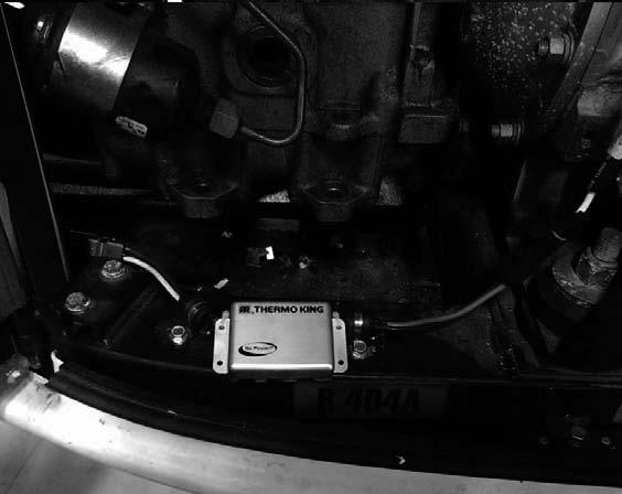
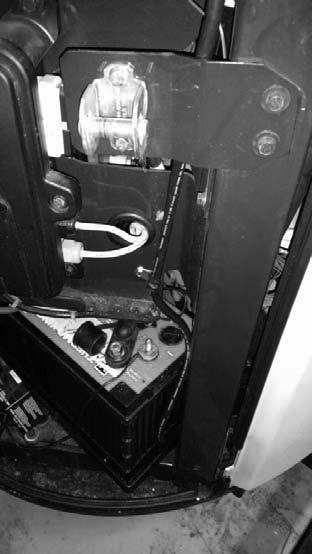
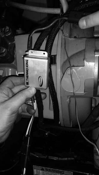
3 Heat King Unit Installation (continued) Figure 4 Figure 5 9. Attach the charge controller harness and route it down the roadside corner frame. 10.Drill ¼ holes into the vertical frame member on either side of the charge controller. 11. Secure the charge controller to the frame on both sides using bandwraps through the ¼ holes and around the charge controller cables (Figure 6). 12.Attach the battery terminal harness to the charge controller and route the white/red lead to the B+ positive terminal on the back of the alternator (Figure 7), add the small brass washers on each side of the harness ring terminal on the B+ stud and torque to 6.0 N m (44-53 lb-in) 13.Attach the black wire to the negative ground cable (Figure 8) or to other secure chassis ground mounting hardware. Verify 0 ohms resistance to ground using a multi-meter. Figure 7 Figure 6 14.Ensure the harness has a drip loop to prevent water from running down onto the terminals 15.Apply sealant to the outer skin hole to prevent excess water from entering the unit during service. 16.Install fuse and return the unit to service. 3 Figure 8
. 4.")

. Alternate method, drill 5/32'' hole at each grommet and secure with #10-14 x 1/2' long thread forming screws. 7.")
4 SB DRC Unit Installation 1. Turn off the unit and disconnect the positive battery cable. 2. Temporarily remove fuse from solar panel harness. 3. Ensure the front surface of the top door skin is clean and free of any dirt (Figure 1). 4. Peel back the top 4 inches of the backing paper and apply the top edge of the panel centered under the Thermo King Crest (Figure 2) with the junction box facing toward the curbside of the unit. 5. With the panel properly positioned, remove the remainder of the backing paper and firmly press the panel into the plastic skin over the entire area of the panel. Repeat several times to ensure the entire panel is properly adhered to the skin and conforms to the curve of the top door 6. Drill 3/16'' holes at each panel grommet. Insert Christmas tree fasteners (10 places). Alternate method, drill 5/32'' hole at each grommet and secure with #10-14 x 1/2' long thread forming screws. 7. Drill a 7/8 hole approx 1 to the left of the edge of the panel (Figure 3). 8. Cut a slit in the provided rubber grommet (330324) and place around the harness exiting the panel. Place the connector through the hole and place the grommet around the hole (Figure 4). 9. Connect the extension harness and attach the harness near the top of the curbside frame member using the provided p-clamps. Ensure the harness routes over the door gas shock and has adequate slack to allow for the door to open and close without interference (Figure 5). 10.Attach the charge controller harness to the extension harness and route it down the curbside frame post to the angle power pack tube and along the frame front tube to the starter. IMPORTANT: Do not route the harness together with the fuel lines. 11. Attach the battery terminal harness to the charge controller and attach the white/red wire to the positive terminal on the starter solenoid (terminal with the battery cable). Attach the black wire to the CH terminal on the throttle solenoid. 12.Secure the charge controller to the bottom frame member on both sides using p-clamps (Figure 6). 13.Secure harness as required with bandwraps and bandwrap anchors. NOTE: Avoid drilling holes in the plastic bulkhead. 14.Apply sealant to the outer skin hole to prevent excess water from entering the unit during service. 15.Install fuse and return the unit to service. Figure 1 Figure 2 Figure 3 4

5 SB DRC Unit Installation (continued) Figure 4 Figure 5 Figure 6 5


 and place around the harness exiting the panel.")
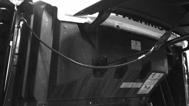
6 Precedent DRC Installation 1. Turn off the unit and disconnect the positive battery cable. 2. Temporarily remove fuse from solar panel harness. 3. Ensure the front surface of the top door skin is clean and free of any dirt. 4. Peel back the top 4 inches of the backing paper and apply the top edge of the panel to the middle door skin just under the Thermo King Crest (Figure 1) with the junction box facing toward the roadside of the unit. The curbside edge should be just inside the curbside door edge. 5. With the panel properly positioned, remove the remainder of the backing paper and firmly press the panel into the plastic skin over the entire area of the panel Repeat several times to ensure the entire panel is properly adhered to the skin and conforms to the curve of the top door. 6. Drill 3/16'' holes at each panel grommet. Insert Christmas tree fasteners (10 places). Alternate method, drill 5/32'' hole at each grommet and secure with #10-14 x 1/2' long thread forming screws. Figure 1 Figure 2 7. Drill a 7/8 hole approx 1 to the left of the edge of the panel. 8. Cut a slit in the provided rubber grommet (330324) and place around the harness exiting the panel. Place the connector through the hole and place the grommet around the hole (Figure 2). 9. Connect the extension harness and route the harness near the top of the roadside door hinge. Secure using band wraps and ensure the door does not bind when closing (Figure 3). Figure 3 6


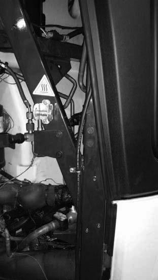
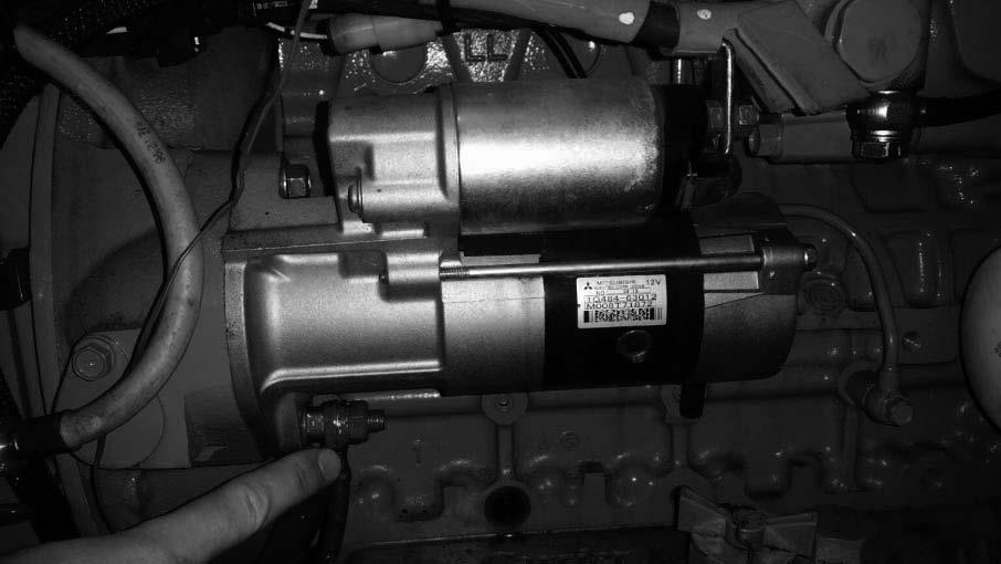
7 10.Route the harness down the roadside wall next to the condenser wall and following existing wires to starter (Figure 4). Ensure that the wire does not touch hot copper tubing and that it is properly band tied to solid structures or other harnesses.coil excess cable as shown (Figure 5). Harness Routing Path Figure 4 Figure Attach the white/red wire to the positive terminal on the starter solenoid (terminal with the positive battery cable (Figure 6). Attach the black wire to the engine block ground stud behind the oil filter (Figure 7). 12.Coil up the extra harness length in front of the starter and secure with bandwraps (Figure 8). 13.Install fuse and return the unit to service. Figure 6 Figure 7 Coil and secure excess harness. Figure 8 7

8 Carrier Installation 1. Turn off the unit and disconnect the positive battery cable. 2. Temporarily remove fuse from solar panel harness 3. Ensure the Carrier Adapter bracket is clean and free of any dirt. 4. Peel back the backing paper and apply the panel to the adapter bracket. Smooth over the entire area of the panel pressing firmly. Repeat several times. The included thread forming screws should be used in addition to the adhesive to provide added assurance. Fasten the panel to the bracket by drilling 5/32'' pilot holes and running the self drilling screws through the grommets on the panel. 5. Position the panel and bracket onto the top of the Carrier unit and center it (Figure 1). Figure 1 6. Ensure that there is no overlapping metal under the plastic skin where the mounting holes will go. Drilling through multiple layers of metal can result in rust between the joints. 7. Using the larger self drilling #12-14 x 1-1/4'' long screws, attach the panel down to the unit metal frame on the four corners starting on the rear frame along the trailer front wall. 8. Using the provided p-clamp and #10-16 x 3/4'' long self drilling screw, secure the harness coming out of the panel to the Carrier adapter bracket (Figure 2). This will ensure it does not touch the exhaust pipe. 9. Connect the extension harness and attach the harness near front curbside frame member using the provided p-clamps and #10-16 x 3/4'' long self drilling screws. Route the harness down the side of unit, ensuring the secure the harness using p-clamps and band wraps (Figure 3 and 4). 10.Attach the charge controller harness to the extension harness and secure it in the front of the unit (Figure 5). IMPORTANT: Do not route the harness together with fuel lines 11. Attach the battery terminal harness to the charge controller and attach the white/red wire to the positive terminal on the starter solenoid (terminal with the battery cable). Attach the black wire to ground stud near the starter (Figure 6). 12.Secure harness as required with bandwraps. 13.Install fuse and return the unit to service. 8
9 Carrier Installation (continued Figure 2 Figure 3 Figure 4 Figure 6 Figure 5 9
. 4. Peel back the backing paper and apply to the plastic bulkhead.")

10 SB III Installation 1. Turn off the unit and disconnect the positive battery cable. 2. Temporarily remove fuse from solar panel harness 3. Ensure the top surface of the unit bulkhead where the panel will be positioned is clean and free of any dirt (Figure 1). 4. Peel back the backing paper and apply to the plastic bulkhead. Ensure the panel will be minimally shaded from any of the outer skins. 5. Drill 5/32'' holes at all panel grommet holes. Secure panel with #10-14 x 1/2'' long thread forming screws (10 places). 6. Attach the extension harness and route down the curbside corner frame. 7. Attach the charge controller and ring terminal harness to the extension harness. 8. Attach the white/red wire to the positive terminal on the starter solenoid (terminal with the battery cable). Attach the black wire to ground stud near the starter (Figure 2). 9. Install fuse and return the unit to service. Figure 1 Positive Ring Terminal Connection Negative Ring Terminal Connection Figure 2 10
11 TEST PROCEDURE To properly test the solar output you must have the following items: Halogen lamp (500W or greater) or be outdoors in the daylight. Voltage meter Amp clamp or ammeter 1. Put voltmeter on the battery and measure the voltage. Voltage must be less than 12.8V for the solar panel controller to turn on. If battery voltage is not less than 12.8V then put a 12V load on the battery. 2. If indoors, put at least a 500W halogen lamp approxiamately 24'' above the solar panel and turn it on. 3. Put voltmeter on the battery. 4. Put amp clamp around the positive cable from the solar panel. Voltage reading should begin increasing or stay the same. Amperage reading should be greater then.300 ma The solar panel controller may take up to a minute to turn on. The solar panel must be connected to the battery in order to turn on the charge controller. 11
12 12
ThermoLite 40W Solar Panel Installation Instructions
 ThermoLite 40W Solar Panel Installation Instructions INSTALL APPLICATIONS SUPPORTED BY THIS GUIDE: 1. Heat King (all models) 40W 2. Precedent Domestic Rail Container (DRC front skin mounted) 40W 3. Tractor
ThermoLite 30W Solar Panel Installation Instructions
 ThermoLite 30W Solar Panel Installation Instructions INSTALL APPLICATIONS SUPPORTED BY THIS GUIDE: 1. SB Unit (30W) 2. Precedent Unit (30W) 3. Carrier Trailer Unit (30W) 4. Test Procedure 401414-30W Solar
ThermoLite 26W Solar Panel Installation Instructions
 ThermoLite 26W Solar Panel Installation Instructions WARNING: Always wear safety glasses and protective gloves when working with batteries. SB Unit Installation 3. Attach adapter bracket (401271) to solar
ThermoLite 110W-330W Solar Panel Installation Instructions
 ThermoLite 110W-330W Solar Panel Installation Instructions INSTALL APPLICATIONS SUPPORTED BY THIS GUIDE: 1. Trailer Roof Top Mounted 2. Bus Roof Top Mounted 3. Tractor Fairing Mounted 40W and 110W Replacement
TECHNICAL INSTRUCTIONS
 TECHNICAL INSTRUCTIONS 76-50213-00 Solar Charger Kit This kit provides the necessary parts and instructions to install an optional Battery Solar Charger Kit. The solar panel charging system will help maintain
TOYOTA VENZA 2009 TRAILER WIRE HARNESS Procedure
 Part Number: PT791-0T099 Kit Contents Item # Quantity Reqd. Description 1 1 Trailer Wire Harness Module 2 1 4-Flat Harness 3 1 Battery Power Wire Harness 4 1 Mounting Bracket, 4-Flat 5 2 Screw #10-24 6
REARSIGHT PART NUMBER: Code: MC1 RECOMMENDED SEQUENCE OF APPLICATION
 Document # 3848 REVISION A 1/26/06 2006 TOYOTA TACOMA REARSIGHT PART NUMBER: 00016-00050 Code: MC1 RE V I S I O N A KIT CONTENTS ITEM QTY DESCRIPTION 1 1 MIRROR/MONITOR 2 1 REAR CAMERA ASSEMBLY 3 1 CAMERA
Installation Manual. Trailer Edition Precedent. Battery Charger Kits and Supplemental Power Package Retrofit Kits
 Installation Manual Trailer Edition Precedent C-600*, C-600M, S-600, S-700, S-600M & S-610M/DE Battery Charger Kits and Supplemental Power Package Retrofit Kits *C-600 CANNOT HAVE SUPPLEMENTAL POWER PACKAGE
Installation Manual. Truck and Trailer Edition CargoLink Installation Manual TK IM (Rev. 4, 1/16)
") Installation Manual Truck and Trailer Edition CargoLink Installation Manual TK 55151-11-IM (Rev. 4, 1/16) Installation Manual Truck and Trailer Edition CargoLink Installation Manual TK 55151-11-IM (Rev.
Installation Manual Truck and Trailer Edition CargoLink Installation Manual TK 55151-11-IM (Rev. 4, 1/16) Installation Manual Truck and Trailer Edition CargoLink Installation Manual TK 55151-11-IM (Rev.
TubeTrace Tubing Bundles
 for Custom CEMS and Analytical Umbilicals English Units Receiving, Storing and Handling... 1. Inspect materials for damage incurred during shipping. Report damages to carrier for settlement. 2. Identify
TOYOTA VENZA 2009 TRAILER WIRE HARNESS Procedure
 Part Number: PT791-0T099 Kit Contents Item # Quantity Reqd. Description 1 1 Trailer Wire Harness Module 2 1 4-Flat Harness 3 1 Battery Power Wire Harness 4 1 Mounting Bracket, 4-Flat 5 2 Screw #10-24 6
ROADMASTER, Inc NE 127th Ave. Vancouver, WA Fax roadmasterinc.com ROADMASTER, Inc.
 ROADMASTER, Inc. 6110 NE 127th Ave. Vancouver, WA 98682 800-669-9690 Fax 360-735-9300 roadmasterinc.com 2008-2017 ROADMASTER, Inc. All rights reserved. 853600-05 11/17 Read all instructions before installing
Installation Items: Cruise Module
 Installation Items: Rostra 250-1223, Electronic Cruise Control System (ECCS) includes the cruise module, harness, cruise cable, cruise module mounting bracket, cruise cable mounting bracket and hardware
PFadvantage Metalfor Araus 1360
 Metalfor Araus 1360 Note: Indented items indicate parts included in an assembly listed above Part Name/Description Part Number Quantity Instruction Kit Metalfor Araus 2005300-14 1 Display Bracket 4000134
GENUINE PARTS INSTALLATION INSTRUCTIONS
 GENUINE PARTS INSTALLATION INSTRUCTIONS 1. 2. 3. 4. DESCRIPTION: Security Light Kit APPLICATION: Altima Coupe and Sedan (2011+) PART NUMBER: 999F4 AX008 - Universal Security Lighting Kit. KIT CONTENTS:
AUXILIARY BATTERY BOX INSTALLATION INSTRUCTIONS
 AUXILIARY BATTERY BOX INSTALLATION INSTRUCTIONS The original TOMMY GATE hydraulic lift Assembling the Auxiliary Battery Box 1. Remove the cover from the auxiliary battery box by removing the two nuts and
WARNING READ ALL INSTRUCTIONS PRIOR TO INSTALLATION
 SUPRA MULTITEMP HOST UNIT S PART NO. MODEL DESCRIPTION KIT NUMBER (REFERENCE) 980336900 SUPRA 950M/T TDD 760053727 WARNING READ ALL INSTRUCTIONS PRIOR TO INSTALLATION 1.0 INSTALLATION OF THIS REFRIGERATION
SAFETY. Read and understand all safety precautions and instructions before installing this product.
 SAFETY Installation Instructions Application: 2015+ FORD F150 Your safety and the safety of others is very important. In order to help you make informed decisions about safety, we have provided installation
TOYOTA CAMRY LE / SE / XLE DUAL SEAT HEATER KIT Section I Pre-Installation Check
 Section I Pre-Installation Check Kit Part Number: 250-1897 3 General Applicability Camry LE / SE / XLE 5 4 1 Recommended Sequence of Application Item # Accessory 1 Wiring 2 Elements 3 2 Kit Contents Item
INSTALLATION & OWNER S MANUAL
 Rev. C p. 1 of 21 INSTALLATION & OWNER S MANUAL F5205 HARD SIDED CAB KIT INSTALLATION & OWNER S MANUAL The contents of this envelope are the property of the owner. Be sure to leave with the owner when
MF 9690, 9790, Challenger 660, 670
 Ag Leader Technology Parts List Note: Indented items indicate parts included in an assembly listed above Quantity by Model Part Name/Description Part No. MF 9690 MF 9790 Challenger 660 Challenger 670 Instruction
REC-11+ REMOTE RECEIVER UNIT
 Resetting The Programmable Features The installer may quickly and easily return all 17 programmable features back to the factory settings. Changing individual features were explained in detail in the previous
Conflicts NOTE: XLE, LE, AND SE MODELS
 TOYOTA SIENNA 2011- REARSIGHT Part Number: 00016-00085 Accessory Code: MC9 Conflicts NOTE: XLE, LE, AND SE MODELS KIT CONTENTS ITEM QTY DESCRIPTION 1 1 MIRROR/MONITOR 2 1 REAR CAMERA ASSEMBLY 3 1 CAMERA
29048, 29049, 29050, 29051, 29052, 29053, 29054,
 April 15, 2014 Lit. No. 29225, Rev. 11 29048, 29049, 29050, 29051, 29052, 29053, 29054, 29400 5 HARNESS KIT 3 PORT ISOLATION MODULE LIGHT SYSTEM w/2 PLUG SYSTEM HARNESSES Installation Instructions Read
Vehicle Rear Observation System With Integrated Parking Sensors
 Vehicle Rear Observation System With Integrated Parking Sensors Model: CAMSBAR Installation/User Manual Features: 2.5" LCD Color Display 2 Ultra Sonic Rear Obstacle Sensors On-screen Display Function Automatically
INSTALLATION INSTRUCTIONS
 INSTALLATION INSTRUCTIONS Models: 7105 & 7105TK Dodge Ram 1500 ('02 Current) Ram 2500 & 3500 '03 - Current with stock manual mirrors. IF YOU DO NOT CURRENTLY HAVE MANUAL MIRRORS, THE WRONG SET HAS BEEN
CTC 200 Cab Trailer Communication Power Line Carrier Technology Communications for Trucks and Trailers
 WHEEL MONITOR CTC 200 Cab Trailer Communication Power Line Carrier Technology Communications for Trucks and Trailers Installation Manual for the CTC-200 Modules 2004 Wheel Monitor Inc. 1-905-641-0024 Page
and Original Series Pickup Lift Mounting Instructions Fleetside Chevy & GMC Trucks Fleetside 4-door Chevy & GMC Trucks T-100
 r ve and Original Series Pickup Lift Mounting Instructions Fleetside Chevy & GMC Trucks - 1960-1987 Fleetside 4-door Chevy & GMC Trucks - 1988-1991 Preparing the Gate 1. Remove the mounting hardware which
PFadvantage MF 6850/6855; Ideal 9080/9090
 MF 6850/6855; Ideal 9080/9090 Note: Indented items indicate parts included in an Quantity by Model assembly listed above MF Ideal Part Name/Description Part Number 6850 6855 9080 9090 Instruction Kit MF
Part Number: TBL-016S
 5/18/17 TOYOTA TUNDRA 2014-2017 LED Truck Bed Light Kit Part Number: TBL-016S Kit Contents Item # Quantity Reqd. Description 1 2 LED Bed Light Harness (10 ) 2 2 LED Bed Light Harness (5 ) 3 1 Y Harness
Installation. minnkot amot or s.com
 Installation minnkot amot or s.com INSTALLATION Your Talon comes complete with the items listed below. Please take a moment to familiarize yourself with the parts list and tools needed prior to starting
29048, 29049, 29050, 29051, 29052, 20953, 29054,
 July 15, 2008 Lit. No. 29225, Rev. 06 29048, 29049, 29050, 29051, 29052, 20953, 29054, 29400-2 HARNESS KIT 3-PORT ISOLATION MODULE LIGHT SYSTEM w/2-plug SYSTEM HARNESSES Installation Instructions Read
GENUINE PARTS INSTALLATION INSTRUCTIONS
 GENUINE PARTS INSTALLATION INSTRUCTIONS DESCRIPTION: APPLICATION: PART NUMBER: KIT CONTENTS: Tow Hitch Wire Harness Kit Quest (2011) 999T8 NW000 Installation of this accessory requires installation of
Instructions for Field Retrofit of a Model 98 Temperature Controller in place of a Model 85 Temperature Controller
 Introduction: Instructions for Field Retrofit of a Model 98 Temperature Controller in place of a Model 85 Temperature Controller The following is a set of instructions for retrofitting a Model 98 Digital
2-row and All-row systems included.
 Ag Leader Technology Cotton Picker Installation Installation Instructions for John Deere cotton picker models: 2-row and All-row systems included. IMPORTANT: Ensure the model numbers shown above correspond
WARNING!! C-659 SUBKIT FIGURE 4
 '0-'0 DODGE / TON TRUCKS '03-' DODGE 3/ & TON TRUCKS (WILL FIT /, 3/ & TON MEGA CAB SHORT BED) WARNING!! BRAKE, FUEL, AND ELECTRICAL LINES MAY NEED TO BE LOOSENED OR REPOSITIONED TO PROVIDE CLEARANCE FOR
INSTALLATION GUIDE. AMP RESEARCH TECH SUPPORT (Press 2) Monday - Friday, 6:00 AM - 5:00 PM PST
 Monday - Friday, 6:00 AM - 5:00 PM PST") INSTALLATION GUIDE APPLICATION AMP Part # Jeep Wrangler Unlimited (JK) 2007 up 75121-01A 2-Door INSTALLATION TIME 3-5 Hours Professional installation recommended SKILL LEVEL 1 2 3 = Experienced TOOLS REQUIRED
INSTALLATION GUIDE APPLICATION AMP Part # Jeep Wrangler Unlimited (JK) 2007 up 75121-01A 2-Door INSTALLATION TIME 3-5 Hours Professional installation recommended SKILL LEVEL 1 2 3 = Experienced TOOLS REQUIRED
Vehicle Wiring Harness and Cab Control
 December 15, 2017 Lit. No. 43777, Rev. 02 Vehicle Wiring Harness and Cab Control For Drop, Low Profile, Single-Stage and Two Stage Tailgate Spreaders Installation Instructions Read this document before
Part Number: TBL-016S
 5/18/17 TOYOTA TACOMA 2016-2017 LED Bed Light Kit Part Number: TBL-016S Kit Contents Item # Quantity Reqd. Description 1 2 LED Bed Light Harness (10 ) 2 2 LED Bed Light Harness (5 ) 3 1 Y Harness Extension
AutoDeploy with Radar. Installation Manual
 AutoDeploy with Radar Installation Manual Revision 1.1; Updated: December 11, 2017 Table of Contents 03 Tool List 04 AutoDeploy Installation 04 Pre-Installation 05 Velocity Sensing Control Unit 06 Warning
GENUINE PARTS INSTALLATION INSTRUCTIONS
 GENUINE PARTS INSTALLATION INSTRUCTIONS DESCRIPTION: APPLICATION: PART NUMBER: Electronic Tailgate Lock Kit Nissan Titan 999M2-W3005 KIT CONTENTS: Item Qty. Part Description Service Part Number A 1 Electronic
CA 421 Installation Instructions
 CA 421 Installation Instructions PROFESSIONAL INSTALLATION STRONGLY RECOMMENDED Installation Precautions: Roll down window to avoid locking keys in vehicle during installation Avoid mounting components
Vehicle Wiring Harness and Cab Control
 April 15, 2016 Lit. No. 43777, Rev. 01 Vehicle Wiring Harness and Cab Control For Low Profile, Single-Stage and Two Stage Tailgate Spreaders Installation Instructions Read this document before installing
JODALE PERRY. Parts List & Mounting Instructions. Jacobsen HR9016 JDP BUILT FOR LIFE
 JODALE PERRY Parts List & Mounting Instructions Jacobsen HR9016 JDP BUILT FOR LIFE Jacobsen HR9016 Mounting Instructions Standard Parts 1 - LH Rear Mounting Bracket 1 - RH Rear Mounting Bracket 1 - Front
49663, 49664, Wiring Conversion Kits. Parts List and Installation Instructions CAUTION. Read this document before installing the snowplow.
 December 1, 2014 Lit. No. 49666, Rev. 01 49663, 49664, 49665 Wiring Conversion Kits Parts List and Installation Instructions Read this document before installing the snowplow. See your sales outlet/web
w w w. h d o n l i n e s h o p. d e HEATED HAND GRIP KITS GENERAL REMOVAL -J02983 REV Kit Number Models Kit numbers Service Parts
 -J098 REV. 007-0-0 GENERAL Kit Number 56047-0B, 5607-0B, 5674-0B, 5696-0B, 565-0B, 5669-0A, 56694-04A, 56750-04A, 5688-0A, 569-05, 5696-05, 56997-07 Models For model fitment information, please see the
GENUINE PARTS INSTALLATION INSTRUCTIONS
 GENUINE PARTS INSTALLATION INSTRUCTIONS 1. 2. 3. 4. DESCRIPTION: Security Light Kit APPLICATION: Altima Sedan (2013+) PART NUMBER: 999F4 AX010 - Universal Security Lighting Kit. KIT CONTENTS: Item QTY
DP K9 Door Popper Installation Manual. Patented
 DP-3000 Patented K9 Door Popper Installation Manual Radiotronics Inc. 1315 SW Commerce Way Stuart FL 34997 Phone: 772-600-7574 Fax: 772-600-7012 www.acek9.com Introduction The K9 Door Popper features a
Installation Manual. TK IM (Rev. 3, 01/12)
") Installation Manual SB-230 RR and SB-330 RR Single Temperature System For Domestic Refrigerated Containers (DRC), Trailer on Flat Car (TOFC) and Rail Box Car (RBC) Applications TK 54932-5-IM (Rev. 3, 01/12)
Installation Manual SB-230 RR and SB-330 RR Single Temperature System For Domestic Refrigerated Containers (DRC), Trailer on Flat Car (TOFC) and Rail Box Car (RBC) Applications TK 54932-5-IM (Rev. 3, 01/12)
Product Name Chair Conversion Kit (to Console Delivery Unit) Installation [Kit # xx]
![Product Name Chair Conversion Kit (to Console Delivery Unit) Installation [Kit # xx]](/thumbs/85/92245042.jpg "Product Name Chair Conversion Kit (to Console Delivery Unit) Installation [Kit # xx]") Elevance Product Name Chair Conversion Kit (to Console Delivery Installation Unit) Installation [Kit #002-1965-xx] Attention: Use this kit to convert an Elevance Chair to a Chair with an Elevance Console
Elevance Product Name Chair Conversion Kit (to Console Delivery Installation Unit) Installation [Kit #002-1965-xx] Attention: Use this kit to convert an Elevance Chair to a Chair with an Elevance Console
JEEVES. JEEVES Installation Manual. Installation Manual The Easiest Do-It-Yourself Dumbwaiter on the Market
 1 888-323-8755 www.nwlifts.com JEEVES Installation Manual The Easiest Do-It-Yourself Dumbwaiter on the Market This manual will cover the installation procedure step-by-step. The installation of this dumbwaiter
Remote engine start INSTALLATION INSTRUCTIONS
 GENUINE Remote engine start INSTALLATION INSTRUCTIONS Thank you for purchasing a genuine Mazda accessory. Before removal and installation, be sure to thoroughly read these instructions. Please read the
TRAIL CHARGER with EXTENDER and COMBO NOSE BOX
 TRAIL CHARGER with EXTENDER and COMBO NOSE BOX 284424 01 Version 1.02 03/14/2011 Owners Manual Operation Installation Wiring Diagram Troubleshooting Parts Breakdown 1 GENERAL OPERATION PROBLEM On applications
GENUINE PARTS INSTALLATION INSTRUCTIONS
 GENUINE PARTS INSTALLATION INSTRUCTIONS 1. 2. 3. 4. DESCRIPTION: APPLICATION: PART NUMBER: KIT CONTENTS: Security light Kit Maxima 999F4 AX009 - Universal Security Lighting Kit. Item QTY Description Service
SYSTIMAX G2 4U Fixed Rear Access Combination Shelf Instructions
 Instruction Sheet 860452176 SYSTIMAX Solutions SYSTIMAX 360 360G2 4U Fixed Rear Access Combination Shelf Instructions General The SYSTIMAX 360 360G2 4U rear access fiber optic combination shelf mounts
Vehicle Wiring Harness and Cab Control
 August 15, 2015 Lit. No. 43777, Rev. 00 Vehicle Wiring Harness and Cab Control For Low-Profile, Two-Stage Tailgate Spreaders Installation Instructions Read this document before installing the spreader.
P Original Series Cargo Van Lift Mounting Instructions Fullsize Ford Van present. Preparing the Gate
 Fullsize Ford Van- 1992-present Preparing the Gate 1. Remove the mounting hardware which is banded to the liftgate. 2. Verify mounting kit (Figure 1 and Table 1). S-400-40 STRAP VAN MOUNTING EAR BENT BRACKET
RAV4 TNS310 (Traffic) Plus
 Plus") TNS310 (Traffic) Plus RHD installation instructions Model year: 005 Vehicle code: **A3***-*****W Part number TNS310 Plus: Sub wire harness No 1: 08673-64801 Sub wire harness No : 08673-64800 Part number
TNS310 (Traffic) Plus RHD installation instructions Model year: 005 Vehicle code: **A3***-*****W Part number TNS310 Plus: Sub wire harness No 1: 08673-64801 Sub wire harness No : 08673-64800 Part number
49663, 49664, Wiring Conversion Kits. Installation Instructions CAUTION. Read this document before installing the snowplow.
 December 1, 2011 Lit. No. 49666, Rev. 00 Wiring Conversion Kits Installation Instructions Read this document before installing the snowplow. See your sales outlet/web site for specific vehicle application
Revision THERMO TECHNOLOGIES. USDT 2001 Differential Controller. Installation and User s Guide
 Revision 8 THERMO TECHNOLOGIES USDT 2001 Differential Controller Installation and User s Guide USDT 2001 DIFFERENTIAL CONTROLLER Installation and User s Guide Table of Contents Introduction General Information
Part Name/Description Part Number Quantity Instruction Kit Metalfor Flow Sensor
 NOTE: Indented items indicate parts included in an assembly listed above Part Name/Description Part Number Quantity Instruction Kit Metalfor 4101091 1 Flow Sensor 4001356 1 Deflector plate 2000612-1 1
Rostselmash Torum 740
 Note: Indented items indicate parts included in an assembly listed above Quantity by Model Part Name/Description Part Number 740 Combine Kit Torum 740 4100762 1 Threaded Arm Assembly 2000311-2 1 Header
650 Series Cargo Van Lift Mounting Instructions Ford Transit (Standard Roof) 2015-Present
 2015-Present") TOMMY GATE OWNER'S / OPERATOR'S MANUAL 650 Series 650 LB Capacity 650 Series Cargo Van Lift Mounting Instructions Ford Transit (Standard Roof) 2015-Present Installing the Base Plate 1. Examine the interior
TOMMY GATE OWNER'S / OPERATOR'S MANUAL 650 Series 650 LB Capacity 650 Series Cargo Van Lift Mounting Instructions Ford Transit (Standard Roof) 2015-Present Installing the Base Plate 1. Examine the interior
SHAVED-DX. Installation Manual & Operation Instructions. Trouble Shooting Reverse Polarity Wiring Problems
 Trouble Shooting Reverse Polarity Wiring Problems Switch doesn't work properly but the shaved kit transmitters do work Step 1 Did you purchase a switch kit designed for three switches and only use two
Installation Manual. Trailer Edition SB-110+, SB-210+ and SB-310+ Single Temperature Systems. TK IM (Rev. 3, 01/10)
") Installation Manual Trailer Edition SB-110+, SB-210+ and SB-310+ Single Temperature Systems TK 53952-2-IM (Rev. 3, 01/10) Copyright 2008 Thermo King Corp., Minneapolis, MN, U.S.A. Printed in U.S.A. Release
Installation Manual Trailer Edition SB-110+, SB-210+ and SB-310+ Single Temperature Systems TK 53952-2-IM (Rev. 3, 01/10) Copyright 2008 Thermo King Corp., Minneapolis, MN, U.S.A. Printed in U.S.A. Release
MF 9520 / 9540 / 9560, Challenger 540C / 560C
 Ag Leader Combine Installation Note: Indented items indicate parts included in an assembly listed above Part Name/Description Part Number 9520 Quantity by Model 9540 540C Parts Kit 2001312-69 1 1 1 Drill
AMP RESEARCH TECH SUPPORT (Press 2) Monday - Friday, 6:00 AM - 5:00 PM PST
 Monday - Friday, 6:00 AM - 5:00 PM PST") APPLICATION AMP Part # Jeep Wrangler Unlimited (JK) 2007 2017 78122-01A (-Door Only) INSTALLATION TIME 3-5 Hours Professional installation recommended SKILL LEVEL 1 2 3 = Experienced TOOLS REQUIRED q 13
APPLICATION AMP Part # Jeep Wrangler Unlimited (JK) 2007 2017 78122-01A (-Door Only) INSTALLATION TIME 3-5 Hours Professional installation recommended SKILL LEVEL 1 2 3 = Experienced TOOLS REQUIRED q 13
GENUINE PARTS INSTALLATION INSTRUCTIONS
 GENUINE PARTS INSTALLATION INSTRUCTIONS 1. 2. 3. 4. DESCRIPTION: Accent light Kit APPLICATION: Versa (2012) PART NUMBER: 999F3 AW008 - Universal Accent Lighting Kit. KIT CONTENTS: Item QTY Description
Networkfleet 3500 Product Line Installation Guide
 Networkfleet 3500 Product Line Installation Guide Light/Medium Duty (L3500) Heavy Duty (H3500) Universal (U3500) www.networkcar.com/fleet Customer Care: (866) 227-7323 customercare@networkcar.com Table
Vehicle Security System
 Installation Instructions Vehicle Security System PROFESSIONAL INSTALLATION STRONGLY RECOMMENDED Installation Precautions: Roll down window to avoid locking keys in vehicle during installation Avoid mounting
4000 SYSTEM OPERATING MANUAL
 4000 SYSTEM OPERATING MANUAL REV 1.4 COPYRIGHT 1996 Xenotech, Inc. PAGE 1 INSTRUCTIONS FOR REMOVING AND INSTALLING A TYPE XT XENON BULB IN A BL4000 FIXTURE NOTE FAMILIARIZE YOURSELF WITH THE LOCATION AND
JOHN DEERE GATOR SWITCH PANEL INSTRUCTIONS FITS 1GTRXUV2 AND 1GTRXUV4 CABS (p/n: 1XUVSP)
") P. 1 of 5 JOHN DEERE GATOR SWITCH PANEL INSTRUCTIONS FITS 1GTRXUV2 AND 1GTRXUV4 CABS (p/n: 1XUVSP) Note: Harness Extension Kit Required for 4 Passenger (p/n: 1XUV4WHEK) This manual is the property of the
P. 1 of 5 JOHN DEERE GATOR SWITCH PANEL INSTRUCTIONS FITS 1GTRXUV2 AND 1GTRXUV4 CABS (p/n: 1XUVSP) Note: Harness Extension Kit Required for 4 Passenger (p/n: 1XUV4WHEK) This manual is the property of the
I N S T A L L A T I O N G U I D E
 I N S T A L L A T I O N G U I D E APPLICATION AMP Part # Jeep Wrangler Unlimited (JK) 2007 2017 78122-01A (4-Door Only) INSTALLATION TIME 3-5 Hours Professional installation recommended SKILL LEVEL 1 2
CA-210 Installation Instructions
 CA-210 Installation Instructions PROFESSIONAL INSTALLATION STRONGLY RECOMMENDED Installation Precautions: Roll down window to avoid locking keys in vehicle during installation Avoid mounting components
INSTALLATION MANUAL. Power-Pole Blade Edition Shallow Water Anchor. Installation Instructions
 INSTALLATION MANUAL Power-Pole Blade Edition Shallow Water Anchor Installation Instructions CAUTION: Read this instruction manual carefully. Become familiar with the controls and know how to operate the
Accessory Harness & Bracket Kit
 Accessory Harness & Bracket Kit Stainless Steel Hopper Spreader Gas 9969 June 5, 06 Lit. No. 98986, Rev. 0 PARTS LIST 9 4 8 7 6 4 3 8 VIB LIGHT STROBE PREWET 5 0 4 9969 Accessory Harness & Bracket Kit
Ford Super Duty Recoil Traction Bar System. Part#: ,
 Part#: 123408, 123409 Ford Super Duty Recoil Traction Bar System Rev. 090817 491 W. Garfield Ave., Coldwater, MI 49036. Phone: 517-279-2135 E-mail: tech-bds@sporttruckusainc.com Read And Understand All
INSTALLATION INSTRUCTIONS
 INSTALLATION INSTRUCTIONS Accessory Application Publications No. AII 44415 2011 CIVIC 4-DOOR Issue Date AUG 2010 PARTS LIST Trunk spoiler 2 Cap nuts 2 Screws Left trunk spring (marked yellow) Right trunk
Installation Instructions for John Deere cotton picker models: 9986 & 2-row and All-row systems included.
 Ag Leader Technology Cotton Picker Installation Installation Instructions for John Deere cotton picker models: 9986 & 9996 2-row and All-row systems included. IMPORTANT: Ensure the model numbers shown
Conflicts. TOYOTA 4Runner REARSIGHT. Part Number: Code: MC90 KIT CONTENTS ADDITIONAL ITEMS REQUIRED FOR INSTALL RECOMMENDED TOOLS
 TOYOTA 4Runner 2010 - REARSIGHT Part Number: 00016-00085 Code: MC90 Conflicts KIT CONTENTS ITEM QTY DESCRIPTION 1 1 MIRROR/MONITOR 2 1 REAR CAMERA ASSEMBLY 3 1 CAMERA EXTENSION HARNESS 4 1 SACK PARTS 5
Service Bulletin No. 3063
 Service Bulletin No. 3063 MODEL TYPE SECTION/GROUP DATE J4500 Series Coaches Service Information 3--Body Aug. 03, 2011 SUBJECT CONDITIONS FENDER PANEL STUD ASSEMBLY Parts may be purchased from MCI Service
w w w. h d o n l i n e s h o p. d e LAYBACK LICENSE PLATE AND TURN SIGNAL RELOCATION KIT INSTALLATION GENERAL -J03892 REV Kit Number
 -J0 REV. 00-0-0 LAYBACK LICENSE PLATE AND TURN SIGNAL RELOCATION KIT GENERAL Kit Number 0-0 Models For model fitment information, please see the P&A Retail Catalog or the Parts and Accessories section
Application Techniques for Reflective Pressure-Sensitive Films
 Introduction Before starting application consult the appropriate product data bulletin for information regarding minimum and maximum application temperatures, recommended substrates, and immediate service
PROPER ELECTRICAL CONNECTIONS
 INSTALLATION 230 Volt 13 ampere 50 Hz The SUITMATE Swimsuit Water Extractor has been designed and manufactured with safety as our primary consideration. Therefore, it is important that the unit be installed
B29048, B29049, B29050, B29051, B29053, B
 May 1, 2011 Lit. No. 48266, Rev. 05 B29048, B29049, B29050, B29051, B29053, B29400-5 HARNESS KIT 3-PORT ISOLATION MODULE LIGHT SYSTEM w/2-plug SYSTEM HARNESSES Installation Instructions Read this document
TOYOTA SIENNA TRAILER WIRE HARNESS Preparation
 Preparation Part Number: PT791-08150 (non-se) PT791-08102 (SE only) Kit Contents Item # Quantity Reqd. Description 1 1 Trailer Module Harness 2 1 4-Flat Harness 3 1 Battery Power Wire Harness 4 1 Mounting
INSTALLATION INSTRUCTIONS
 GENUINE PARTS INSTALLATION INSTRUCTIONS 1. DESCRIPTION: Rear s 2. APPLICATION: Titan King Cab and Crew Cab 3. PART NUMBER: 999N4 WQ1CC and 999N4 WQ1KC 4. KIT CONTENTS: Item No. Qty Description 1) 1, 60
Solar Pack Installation
 Solar Pack Installation The WireFree TM Solar Pack harnesses renewable solar energy to power WireFree TM motorized window coverings. This innovative product from Somfy is easy to install, and provides
INSTALLATION INSTRUCTIONS
 INSTALLATION INSTRUCTIONS Accessory Application Publications No. AII 40454 XM SATELLITE RADIO 2009 S2000 Issue Date AUG 2008 PARTS LIST Template XM Radio Unit Kit (sold separately): P/N 08A53-S2A-101 XM
GENUINE Interior Lighting Kit
 GENUINE Interior Lighting Kit INSTALLATION INSTRUCTIONS Thank you for purchasing a genuine Mazda accessory. Before removal and installation, be sure to thoroughly read these instructions. Please read the
1 Part Number: Part Description: Mustang GT-Shelby Style Electric Exhaust Valve Wiring Installation Instructions
 Please visit www.fordperformanceracingparts.com for the most current instruction and warranty information. PLEASE READ ALL OF THE FOLLOWING INSTRUCTIONS CAREFULLY PRIOR TO INSTALLATION. AT ANY TIME YOU
T-52. r ve Pickup Lift Mounting Instructions Chevy / GMC- Colorado/ Canyon: 2015-present. Preparing the Gate. Installing the Bolt-on Gussets
 Chevy / GMC- Colorado/ Canyon: 2015-present Preparing the Gate 1. Remove the mounting hardware which is banded to the liftgate. 2. Verify mounting bracket kit (Figure 1 and Table 1). LEFT BRACKET (RIGHT
GENUINE PARTS INSTALLATION INSTRUCTIONS
 GENUINE PARTS INSTALLATION INSTRUCTIONS 1. 2. 3. 4. DESCRIPTION: APPLICATION: PART NUMBER: KIT CONTENTS: Accent light Kit Versa Note 999F3 4Z000 - Accent Lighting Kit. 999Q9 AY000 - Accessory Service Connector
Installation Instructions
 Installation Instructions www.bestop.com - We re here to help! Visit our web site and click on Ask a Question INSTALLATION TIME SKILL LEVEL Automatic Retracting Running Board Vehicle Application Chevy
Designed for 2014 and newer 1500 Series and 2015 and newer Heavy Duty GM Silverado/Sierra Double Cab vehicles
 19303116 Designed for 2014 and newer 1500 Series and 2015 and newer Heavy Duty GM Silverado/Sierra Double Cab vehicles Subwoofer Assembly Subwoofer Body Harness 25A Fuse Wire Ties x 6 Wire Taps x 2 Adapter
GPS AutoSteer System Installation Manual
 GPS AutoSteer System Installation Manual Supported Vehicles New Holland Combines CR 9040 CX 9040 CR 9050 CX 9050 CR 9060 CX 9060 CR 9070 CX 9070 CR 9080 CX 9080 IntelliSteer Ready PN: 602-0231-01-A LEGAL
Stay-IN-Play with Panic Stop Braking
 INSTALLATION INSTRUCTIONS TOWED VEHICLE BRAKING SYSTEM Stay-IN-Play with Panic Stop Braking SMI Manufacturing, Inc. P.O. Box 14040 Evansville, IN 47728 1-800-893-3763 www.smibrake.com SIP0906 Model SIP0603
and Original Series Pickup Lift Mounting Instructions T-150-T T-150 PART#5177 T-150-T
 Fullsize Chevy & GMC Trucks- 988-999 Toyota Tundra- 2000-2006 Toyota T-00-993-999 Preparing the Gate r ve and Original Series Pickup Lift Mounting Instructions. Remove the mounting hardware which is banded
PFadvantage JD 3300/4400/6600/7700; 4420
 Ag Leader Technology Combine Installation JD 33//66/77; 2 Note: Indented items indicate parts included Quantity by Model in an assembly listed above Early Late Part Name/Description Part Number 3 3 6 6
Owners Manual: Flow Through Filter (FTF) System
 System") PROVENTIA EMISSION CONTROL carb-verified, level 2+ tru Filter RETROFIT Owners Manual: Flow Through Filter (FTF) System Including Installation Guide for SB Model TRUs Proventia Americas, LLC c/o Proventia
PROVENTIA EMISSION CONTROL carb-verified, level 2+ tru Filter RETROFIT Owners Manual: Flow Through Filter (FTF) System Including Installation Guide for SB Model TRUs Proventia Americas, LLC c/o Proventia