INSTALLATION MANUAL FOR. The. Landing Gear Position Warning System for Land Aircraft. For Experimental Category Aircraft Only Not FAA Approved
|
|
|
- Osborn Potter
- 6 years ago
- Views:
Transcription
1 INSTALLATION MANUAL FOR The Landing Gear Position Warning System for Land Aircraft For Experimental Category Aircraft Only Not FAA Approved P/N SPECIFICATION IM 2050 REV Approved Aircraft Components Inc Harbor Lake Drive Safety Harbor"> INSTALLATION MANUAL FOR The Landing Gear Position Warning System for Land Aircraft For Experimental Category Aircraft Only Not FAA Approved P/N SPECIFICATION IM 2050 REV Approved 1/10
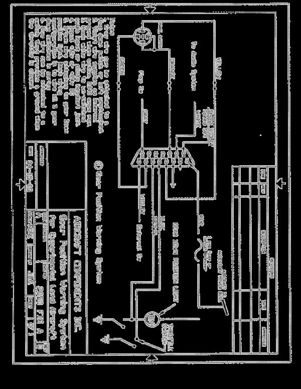
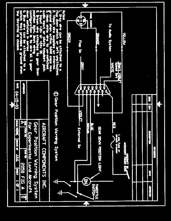
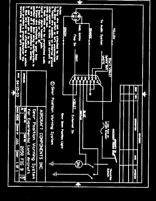
2 Aircraft Components Inc Harbor Lake Drive Safety Harbor, FL I. INTRODUCTION This manual provides information for installing the P/N 2050 Landing Gear Warning System on an Experimental category retractable gear aircraft. All installation work is to be performed in accordance with this manual. II. SYSTEM OPERATION The Landing Gear Warning System is an electronic device which provides the pilot of a retractable gear experimental category aircraft with information on the position of the landing gear prior to a runway landing. The system consists of a small electronic module, and a panel mounted switch, and it connects to the aircraft landing gear DOWN position indicating light. The system is activated by airspeed on takeoff Once the airspeed has exceeded a pre selected speed, a light in the panel switch will illuminate indicating that the system is active. A delay of 15 sec. is built into the unit to allow for airspeed transients. As the aircraft slows for landing, the system enters the warning mode. The electronics check the gear Down position light to determine if the landing gear is down for a runway landing. If the gear is down, pilot will then hear the message GEAR OK in his headset, and through the built in speaker. If the gear is not in the correct position, he will hear the message CHECK LANDING GEAR, CHECK LANDING GEAR repeatedly until the gear is placed in the proper [position, or the airspeed is increased above the activation speed. The system incorporates a test function, and the ability to temporarily disengage operation for slow flight. Pushing the panel switch in flight or on the ground will initiate a test sequence. If the electronics are functioning, the voice message TEST O.K. will be heard. If the panel switch is held for 2 sec., the system will be deactivated. The light in the panel switch will then flash indicating that the system is deactivated. Pushing the switch again, re engages the system and turns the flashing light off. The system also has optional inputs that allow the installer to hook up a switch on the flaps and a switch on the throttle. When these options are used, closing the throttle or lowering the flaps with the gear up, will produce the warning message. The voice messages can be heard through the speaker built into the unit, and directly in the pilots headset. If the aircraft has an audio panel with an un switched input, the voice message will also play through the cabin speaker. NOTE: THIS IS AN ADVISORY SYSTEM ONLY. IT SHOULD NOT BE UTILIZED AS THE PRIMARY MEANS OF DETERMINING GEAR POSITION. THE PILOT SHOULD CONTINUE TO UTILIZE THE NORMAL OPERATING PROCEDURES, CHECKLISTS, LIGHTS, INDICATORS, ETC. AS THE PRIMARY INDICATION OF GEAR POSITION. III APPLICABILITY This system is not FAA approved. It is intended for installation on Experimental category aircraft only. The aircraft must have the following minimum requirements for an installation : 1. 12v or 24v DC power 2. A minimum of one gear down position indicating light, or an electrical switch which activates when the gear is up and when the gear is down. 3. An audio panel with an un switched audio input or a headset jack for the pilot. The system is designed to operate with a variety of light and limit switch wiring configurations. See the attached Installation Schematics, or contact the manufacturer for installation information with other wiring schemes. IV. INSTALLATION INFORMATION A. Mechanical Installation 1. Locate a place in the aircraft to mount the P/N 2050 electronic module. The unit can be mounted to the aircraft structure, side panels etc. Drill 4 mounting holes as shown on Fig 1, and mount the unit using the hardware provided. 2. Drill a 5/16 dia hole in the instrument panel in a location in front of and in easy reach of the pilot, and install the P/N Switch assembly. Place the panel label over the hole before inserting the switch. 3. Attach the 3/16 inch OD (1/8 inch ID) plastic tube on the electronic module to the pressure line from the pitot tube. Do not use a bend radius less than 1 inch, and do not crush the tube when securing it. B. Electrical Installation 1. Refer to Fig A, or Fig B, for information on the electrical installation that fits the wiring configuration in your aircraft. Fig A is the wiring configuration for aircraft that have gear position indicating lights wired so that power is always applied to the lights, and the switches then supply a 2/10
3 ground to turn the lights on. Fig B is the wiring configuration for aircraft that have gear position indicating lights that are wired so that the switches supply power to the lights to turn them on. The system can also be used with aircraft that do not have indicating lights, but do have up and down limit switches on the gear position. Contact the factory for information on this installation. If you have individual indicator lights, and wish to hook all of them up, this can be done also. Contact the factory for information on this configuration. 2. Hook the RED wire to the aircraft power buss through a 1 amp fuse or circuit breaker. The system works with both 12v and 24v power. 3. Attach the BLACK wire to a good aircraft ground. 4. NOTE: Installations made using Fig B require that a jumper be installed in the cable connecter. Remove the gray plastic cover from the cable connecter and solder a jumper from pin 2 to pin 3 in the connecter. Attach the correct color wire to the gear down lights or switches as shown on the correct figure. Note: The short VIOLET wire is for speed calibration. 5. The system incorporates a standard audio output. The audio output must be hooked into the aircraft audio system in a way that the pilot cannot accidentally turn it off. If the aircraft has an audio panel that incorporates an un switched audio input, the Gear Alert audio output should be hooked to this point. This will provide a voice warning directly into the pilots headset and through the cabin speaker. Hook the WHITE wire to this un switched audio input. If the aircraft does not have an audio panel with an un switched input, then the WHITE wire can be hooked directly to the pilots headset jack. 6. The system can be attached to a switch on the flaps that provides a ground when the flaps are fully deflected. This switch closure will provide a second means of activation when landing. This input can be left unused if desired. 7. The system incorporates an airspeed activated switch which can be used to activate an external device like a transponder, a hobbs meter, etc. The system provides a switch closure, (a ground) at an airspeeds above 40 mph, and opens (turns off) at speeds below 40 mph.. NOTE: The switch current must be externally limited to 40 ma. 8. The system can also be attached to a switch on the throttle that provides a ground when the throttle is closed. This switch closure will provide an additional means of activation when landing. This input can be left unused if desired 9. Cut any remaining wires and insulate the ends. Secure all wiring in place. V. SYSTEM CHECKOUT AND OPERATION A. Ground Testing 1. Turn on the master switch. The system must not operate. Push the panel switch momentarily and release it. The voice message TEST OK must be heard once through the built in speaker and through the pilots headset. The voice message will also be heard through the cabin speaker and all headsets in the aircraft if the audio is attached to an un switched input in the audio panel. The volume level of the audio through the cabin speaker and the headsets can be adjusted by turning a volume control pot in the electronic module. Clockwise increases volume, CC decreases it. Locate the correct pot in the electronic module, and using a small screwdriver turn the pot to change the volume level. 2. Push the panel switch and hold it for about 2 sec. The voice message TEST OK will play. When you release the switch the built in light will flash indicating that the system has been disengaged and will not function when landing. Push the switch again momentarily and release it. The flashing light must go off indicating that the system has reactivated. B. Setting the Activation Speed 1. The activation airspeed can be adjusted over a wide range (40 MPH to 90 MPH) by a pot in the electronic module. Locate the correct pot in the electronic module, and use a small screwdriver to adjust it. 2. Attach a digital voltmeter between the short VIOLET wire attached to pin 9 of the connecter and aircraft ground. Using the table of voltage vs activation speed, adjust the speed control pot to set the desired system activation speed. NOTE: The activation speed should be set lower than the normal climb speed to prevent system activation when climbing. Insulate and secure the short VIOLET wire when finished. C. Flight Testing 1. Make a normal takeoff. If the external switch is connected to an accessory, it should activate at about 40 mph. 2. Increase the airspeed until the yellow light illuminates indicating that the system is active. Adjust the activation speed if necessary. Note: The airspeed must be above the activation speed for about 15 sec before the system becomes active. 3/10

4 3. Decrease airspeed below the activation airspeed with the landing gear retracted. The voice message CHECK LANDING GEAR, CHECK LANDING GEAR must be heard in the pilots headset and through the built in speaker. Lower the landing gear and the voice message GEAR OK must be heard, and the amber light must turn off. 4. If the flap switch or the throttle switch options have been hooked up, their operation should be verified by testing as above. 5. When in flight, push the panel switch momentarily and release it. The voice message TEST OK will be heard once through the built in speaker and through the pilots headset. 6. Push the panel switch and hold it for about 2 sec. The voice message TEST OK will play. When you release the switch the built in light will flash indicating that the system has been disengaged and will not function when landing. Push the switch again momentarily and release it. The flashing light will go off and a steady light will be on, indicating that the system has reactivated. VI. DOCUMENTATION 1. The installer is responsible for all documentation, logbook entries, revising weight and balance, etc. 2. System weight is 0.7 lb. Wiring Landing gear Position Lights The landing gear position indicating lights can be wired in a variety of ways. We recommend that the switches on the 2 or 3 landing gear that provide the gear down indication be wired with the switches hooked in series. We also recommend that separate circuit breakers be used for the position lights and the gear warning system. This configuration and this redundancy provides the best system. Should the wiring break, the switches fail, or the breaker for the gear position lights open, the pilot will always get a warning alerting him of the unsafe condition and to check the gear position. This fail safe feature is not always available with other wiring configurations. The sketch below shows the 2 configurations. The system can be wired so that the light is always powered and the switches provide a ground, or they can be wired with one side of the light grounded, and the switches then providing power. If you have 3 retractable gear with separate indicator lights for each wheel, one way is to only hook up the nose wheel. Another configuration involves installing diodes ( P/N 1N4007 ) in the wiring coming from the individual indicating lights as shown on the attached sketch. The sketches address the wiring configurations where the switches provide either power or ground when they close. Be aware that there is a disadvantage with these configurations. Both of these wiring configurations require that the gear indicating light system provide power on the inputs to the Black Box for correct operation. If the circuit breaker for the position lights opens, or a wire breaks such that no power is applied to the brown wire, there is the possibility that the gear warning system could mal function. 4/10
5 5/10

6 6/10

7 7/10
8 8/10
9 9/10
10 10/10
4-1. Engine Starting Procedure
 CSP-CI-ll Section IV Normal Procedures 4-1. Engine Starting Procedure CAUTION Do not abuse the overspeed limiter by starting the engine with the throttle open excessively, or by suddenly advancing throttle
Changed links from specific to general to account for ever-changing and broken links.
 Flight Training Supplement FTS page iii REV 1: Added the following note to the table of contents "NOTE: Pages 4-7 4-9, 5-7, 5-9, 6-3 and 6-5 correspond to a particular EFIS installation. Please remove
INDEX. Preflight Inspection Pages 2-4. Start Up.. Page 5. Take Off. Page 6. Approach to Landing. Pages 7-8. Emergency Procedures..
 INDEX Preflight Inspection Pages 2-4 Start Up.. Page 5 Take Off. Page 6 Approach to Landing. Pages 7-8 Emergency Procedures.. Page 9 Engine Failure Pages 10-13 Propeller Governor Failure Page 14 Fire.
COLUMBIA 350 EMERGENCY PROCEDURES
 COLUMBIA 350 EMERGENCY PROCEDURES TABLE OF CONTENTS EMERGENCY PROCEDURES LANDING AND TAKEOFF Engine Failure During Takeoff...1 Engine Failure Immediately After Takeoff...1 Engine Failure During Climb to
SEAREY HARNESS. INSTALLATION MANUAL for SEAREY AMPHIBIAN AIRCRAFT. P/N 2076 (914 version) & PN 2077 (912 version)
 & PN 2077 (912 version)") SEAREY HARNESS INSTALLATION MANUAL for SEAREY AMPHIBIAN AIRCRAFT P/N 2076 (914 version) & PN 2077 (912 version) SPECIFICATION IP-2076-914 SeaRey SPECIFICATION IP-2077-912 SeaRey REV. 16 December 6, 2013
SEAREY HARNESS INSTALLATION MANUAL for SEAREY AMPHIBIAN AIRCRAFT P/N 2076 (914 version) & PN 2077 (912 version) SPECIFICATION IP-2076-914 SeaRey SPECIFICATION IP-2077-912 SeaRey REV. 16 December 6, 2013
CIRRUS AIRPLANE MAINTENANCE MANUAL
 ELECTRICAL LOAD DISTRIBUTION. DESCRIPTION The power distribution system for this airplane consists of the main distribution bus and the essential distribution bus in the MCU along with the associated buses
Embraer Systems Summary [Landing Gear & Brakes]
![Embraer Systems Summary [Landing Gear & Brakes]](/thumbs/87/96901154.jpg "Embraer Systems Summary [Landing Gear & Brakes]") GENERAL DESCRIPTION The airplane has two main landing gears and a single nose gear. Each main gear is a conventional two-wheeled landing gear. The nose gear is a conventional steerable two-wheeled unit.
GENERAL DESCRIPTION The airplane has two main landing gears and a single nose gear. Each main gear is a conventional two-wheeled landing gear. The nose gear is a conventional steerable two-wheeled unit.
Robin R2120U Take Off Checklist Page 1/5
 Robin R2120U Take Off Checklist Page 1/5 Passenger Briefing Position and use of ELT, first aid kit & axe if applicable Seat and seat belt operation Canopy close & release operation Use of radio & headset,
SERVICE MANUAL & ICA
 WIPLINE FLOATS SKIS MODIFICATIONS AIRCRAFT SALES AVIONICS INTERIOR MAINTENANCE PAINT REFINISHING SERVICE MANUAL & ICA for the AMPHIBIAN GEAR ADVISORY SYSTEM MkII and LASER GEAR ADVISORY SYSTEM Document
SmartStart. Model: SS-12v
 SmartStart Model: SS-12v SmartStart is an electronic control module for the engine starter system on aircraft. SmartStart improves the safety and security of push-button or keyswitch starting systems by
TECNAM P2004 BRAVO N128LS
 TECNAM P2004 BRAVO N128LS GENERAL INFORMATION NORMAL PROCEDURES TIME SENSITIVE EMERGENCY TECNAM P2004 BRAVO CHECKLIST [FLIGHT PLAN DESIGNATION IS BRAV ] EMERGENCY CONTACT The following are First Landings'
Cessna 172RG WARNING. Maximum Demonstrated Crosswind. Takeoff or landing..15 KTS
 Cessna 172RG INTRODUCTION: This aircraft checklist contains information from the original manufacturer s Pilot Information Manual. Normal procedures associated with optional systems can be found in Section
LOG OF REVISIONS. Model G58 Baron (Serials TH-2125 and After) Pilot s Operating Handbook and FAA Approved Airplane Flight Manual
 Pilot s Operating Handbook and FAA Approved Airplane Flight Manual") LOG OF REVISIONS Model G58 Baron (Serials TH-2125 and After) Pilot s Operating Handbook and FAA Approved Airplane Flight Manual Revision A12 - May, 2015 Title Page LOEP LOR Section 1 All Reformatted to
LOG OF REVISIONS Model G58 Baron (Serials TH-2125 and After) Pilot s Operating Handbook and FAA Approved Airplane Flight Manual Revision A12 - May, 2015 Title Page LOEP LOR Section 1 All Reformatted to
Interior Pre Flight Documents: Check Control Wheel Lock: Remove Flight Controls: Check Instruments: Check for Damage Switches: Verify All Off Master
 Interior Pre Flight Documents: Check Control Wheel Lock: Remove Flight Controls: Check Instruments: Check for Damage Switches: Verify All Off Master Switch ALT/BAT: On Fuel Gauge: Check Quantity Flaps:
PA , Model E Normal Checklist (04/15/11)
") PA-23-250, Model E Normal Checklist (04/15/11) Key Airspeeds IAS-MPH V NE 249 V NO 198 V LO/LE 150 V A (At max gross weight.) 149 Speed for single engine cruise. 138 V FE Quarter Flaps 160 Half Flaps 140
PA-23-250, Model E Normal Checklist (04/15/11) Key Airspeeds IAS-MPH V NE 249 V NO 198 V LO/LE 150 V A (At max gross weight.) 149 Speed for single engine cruise. 138 V FE Quarter Flaps 160 Half Flaps 140
1. SUBJECT: Cyclic Trim System Cyclic Trim Assembly Kit for the Lateral and Longitudinal Trim Actuator Assemblies
 DATE: January 23, 2012 SERVICE DIRECTIVE BULLETIN NO. 0110 Page 1 of 9 1. SUBJECT: Cyclic Trim System Cyclic Trim Assembly Kit for the Lateral and Longitudinal Trim Actuator Assemblies 2. MODEL: All F-28F,
SECTION III HYDRAULICS & LANDING GEAR
 TABLE OF CONTENTS Pilot s Manual SECTION III HYDRAULICS & LANDING GEAR Hydraulic System... 3-1 Firewall Shutoff Valves... 3-2 Source Selector Valve... 3-2 AUX HYD Pump Control... 3-2 Main/Auxiliary System
TECNAM P92 EAGLET N615TA TECNAM P92 EAGLET CHECKLIST [FLIGHT PLAN DESIGNATION IS ECHO ]
![TECNAM P92 EAGLET N615TA TECNAM P92 EAGLET CHECKLIST [FLIGHT PLAN DESIGNATION IS ECHO ]](/thumbs/86/93080937.jpg "TECNAM P92 EAGLET N615TA TECNAM P92 EAGLET CHECKLIST [FLIGHT PLAN DESIGNATION IS ECHO ]") TECNAM P92 EAGLET CHECKLIST [FLIGHT PLAN DESIGNATION IS ECHO ] EMERGENCY CONTACT The following are First Landings' emergency contact telephone numbers. We ask that you call the numbers in the order listed.
TECNAM P92 EAGLET CHECKLIST [FLIGHT PLAN DESIGNATION IS ECHO ] EMERGENCY CONTACT The following are First Landings' emergency contact telephone numbers. We ask that you call the numbers in the order listed.
Electrical Options Booklet. Table of Contents
 *24228413* 24228413 Electrical Options Booklet Table of Contents EL Wiring... EL Troubleshooting... SD/EL 98/99 Cylinder Dogging... SS Wiring... 330, 350, RX-330 and RX-350 Push Bar Trim Mechanical Installation...
Aircraft Checklist Commander 114
 Aircraft Checklist Commander 114 This is an abbreviated checklist. Most explanatory items, notes cautions and warnings have been omitted for brevity. Procedures in red/bold text in this checklist should
USAF Aero Club T-41B (Cessna R-172E) Aircraft Exam Updated February 2017
 Aircraft Exam Updated February 2017") USAF Aero Club T-41B (Cessna R-172E) Aircraft Exam Updated February 2017 Instructions Complete the supplement following exam using the answer sheet provided. Do not assume information not specifically
USAF Aero Club T-41B (Cessna R-172E) Aircraft Exam Updated February 2017 Instructions Complete the supplement following exam using the answer sheet provided. Do not assume information not specifically
Pilot's Operating Handbook Supplement AS-03
 POH / AFM SECTION 9 Pilot's Operating Handbook Supplement ASPEN EFD1000 PFD This supplement is applicable and must be inserted into Section 9 of the POH when the Aspen Avionics Evolution Flight Display
Normal Takeoff Procedure. Aborted Takeoff Procedure Engine Failure on Takeoff
 Normal Takeoff Procedure Throttles 2000 RPM Engine Instruments Green Smoothly apply full throttles Airspeed alive V R 90 MPH Remain in ground effect until V MCA 1000 AGL or safe altitude Accelerate to
CARENADO COPYRIGHTS. Normal & Emergency Checklist
 NORMAL PROCEDURES CHECKLIST PREFLIGHT CHECK Control wheel -- RELEASE BELTS Avionics -- OFF Master Switch -- ON Fuel quantity gauges -- CHECK Master switch -- OFF Ignition -- OFF Exterior -- CHECK FOR DAMAGE
NORMAL CHECKLIST ATTENTION!
 Avion Training CHECKLIST Normal Checklist CESSNA 172R / TC-STS Cessna 172 R TC-STS NORMAL CHECKLIST ATTENTION! DO NOT STOW THIS CHECKLIST IN DIRECT SUNLIGHT Avion Training - Doc.nr. 212 Revision 1 / 02022018
Model No. SB1B-14 Linear Standby Regulator. B & C Specialty Products P.O. Box B Newton, KS (316)
") Installation Instructions for Model No. SB1B-14 Linear Standby Regulator With Over-Voltage Protection B & C Specialty Products P.O. Box B Newton, KS 67114 (316) 283-8000 SB1B-14_Install, Rev. A (12/12/14)
Installation Instructions for Model No. SB1B-14 Linear Standby Regulator With Over-Voltage Protection B & C Specialty Products P.O. Box B Newton, KS 67114 (316) 283-8000 SB1B-14_Install, Rev. A (12/12/14)
ROTORCRAFT FLIGHT MANUAL SUPPLEMENT for AS350 Series Helicopter. Registration Number: _. Serial Number: -----
 ROTORCRAFT FLIGHT MANUAL SUPPLEMENT for AS350 Series Helicopter Registration Number: _ Serial Number: ----- This Electrical System Upgrade installed in accordance with STC SH4747NM requires this supplement
2012 AeroLEDs LLC Rev: A Page 1
 Document 0013-0004 Installation Guide: AeroLEDs LLC Sunbeam 967 East Park Center Boulevard P/N 90-1000 Suite # 381 LED Landing light with Boise, ID 83706-6700 built-in pulse recognition mode Phone: (208)
Landing Gear & Brakes
 EMBRAER 135/145 Landing Gear & Brakes GENERAL The EMB-145 landing gear incorporates braking and steering capabilities. The extension/retraction, steering and braking functions are hydraulically assisted,
Senior Swing Control Box. Table of Contents
 *740100* 740100 2800 Overhead Consealed Series 9500 Surface Applied Series Senior Swing Control Box Installation Instructions important These instructions are presented in step-by-step sequence. It is
A310 MEMORY ITEMS Last Updated: 20th th October 2011
 A310 MEMORY ITEMS Last Updated: 20th th October 2011 1. Emergency Descent: Crew Oxygen Mask ON Crew Communication (Headsets) Establish Turn Initiate Descent Initiate o It is recommended to descend with
Vso 61. Vs1 63. Vr 70. Vx 76. Vxse 78. Vy 89. Vyse. 89 (blue line) Vmc. 61 (radial redline) Vsse 76. Va 134) Vno 163
 Vmc. 61 (radial redline) Vsse 76. Va 134) Vno 163") PA34-200T Piper Seneca II Normal procedures V-speeds Knots Vso 6 Vs 63 Vr 70 Vx 76 Vxse 78 Vy 89 Vyse Vmc 89 (blue line) 6 (radial redline) Vsse 76 Va 2-36(@4507lbs 34) Vno 63 Vfe 38 (0*)/2(25*)/07(40*)
PA34-200T Piper Seneca II Normal procedures V-speeds Knots Vso 6 Vs 63 Vr 70 Vx 76 Vxse 78 Vy 89 Vyse Vmc 89 (blue line) 6 (radial redline) Vsse 76 Va 2-36(@4507lbs 34) Vno 63 Vfe 38 (0*)/2(25*)/07(40*)
Safety-TrimTM. Dual axis servo controller. with 2 speed presets
 Safety-TrimTM Dual axis servo controller Models: ST-2-12v ST-2-12v-2sp with 2 speed presets Safety-Trim is an electronic speed controller designed specifically to operate electric servo motors such as
Registration Number. Serial Number
 Registration Number Serial Number This supplement must be attached to the DMCR Approved Airplane Flight Manual dated October 1, 1954 or later approved revision and must be carried in the airplane when
Model No. LR3C-14 and LR3C-28 Linear Regulator
 Technical Manual for Model No. LR3C-14 and LR3C-28 Linear Regulator With Over-Voltage Protection, Low-Voltage Sensing, And Field-Adjustable Charging Voltage Including: Installation Instructions; Troubleshooting
SERVICE NOTICE. 1. The configuration of each Garmin LRU specific to the KODIAK The Garmin LRU software.
 SUBJECT: G1000 Configurations and Updates EFFECTIVITY: As required BACKGROUND This Service Notice is to make customers aware of the different software configurations available for their G1000-equipped
DASSAULT AVIATION Proprietary Data
 F900EX EASY 02-27-00 CODDE 1 PAGE 1 / 2 TABLE OF CONTENTS 02-27 02-27-00 TABLE OF CONTENTS 02-27-05 GENERAL Introduction Flight control sources Primary and secondary flight controls 02-27-10 DESCRIPTION
CHECKLIST 1969 CESSNA 172-K. NOTE: Verify all information with airplane's POH
 CHECKLIST 1969 CESSNA 172-K NOTE: Verify all information with airplane's POH PRE-FLIGHT INSPECTION 1 CABIN 1 A.R.R.O.W. CHECK Airworthiness Cert. In Clear View Registration In Clear View Radio License
N1523J CHECKLIST PA Nebraska Flight Center Eppley Airfield 3737 Orville Plaza Omaha, NE Tel. (402)
") CHECKLIST N1523J 1967 Cherokee 140 PA-28-140 F Nebraska Flight Center Eppley Airfield 3737 Orville Plaza Omaha, NE 68110 Tel. (402) 342-4314 www.nebflight.com Piper Cherokee 140 N1523J 1967 GENERAL INFORMATION
CHECKLIST N1523J 1967 Cherokee 140 PA-28-140 F Nebraska Flight Center Eppley Airfield 3737 Orville Plaza Omaha, NE 68110 Tel. (402) 342-4314 www.nebflight.com Piper Cherokee 140 N1523J 1967 GENERAL INFORMATION
Cessna 172 Skyhawk. Aircraft Checklist Models: R & S
 Cessna 172 Skyhawk Aircraft Checklist Models: R & S This is an abbreviated checklist. Most explanatory items, notes cautions and warnings have been omitted for brevity. Procedures in red/bold text in this
DCS L-39 ALBATROS REAL PILOT START-UP, TAXI AND TAKEOFF CHECKLISTS V 1.0 PREPARED BY LINO_GERMANY
 DCS L-39 ALBATROS REAL PILOT START-UP, TAXI AND TAKEOFF CHECKLISTS V 1.0 PREPARED BY LINO_GERMANY T.O. 1T-L39C-1.0 P1 INTRODUCTIONS A. CHECKLISTS This compilation contains amplified normal and (hopefully
SCION tc Navigation System Preparation. Part Number: PT
 Preparation Part Number: PT611-21111 Kit Contents Item # Quantity Reqd. Description 1 1 Navigation System 2 1 GPS Antenna 3 1 Bluetooth Antenna 4 1 Wire Harness (Reverse / Park Brake) 5 1 RCA Relay Cable
FLIGHT SIMULATOR SYSTEMS
 FLIGHT SIMULATOR SYSTEMS 1. GENERAL This section describes systems required for simulator operation. This equipment includes the Cirrus Landing Gear Simulator (CLGS). 2. DESCRIPTION The intent of the CLGS
GACE Flying Club Aircraft Review Test 2018 N5312S & N5928E. Name: GACE #: Score: Checked by: CFI #:
 GACE Flying Club Aircraft Review Test 2018 N5312S & N5928E Name: GACE #: Score: Checked by: CFI #: Date: (The majority of these questions are for N5312S. All N5928E questions will be marked 28E) 1. What
Checklist Robin DR40
 Flight Checklist for Normal Operations Massgebend ist das AFM (Parameters, Restrictions, Emergency, etc.) Jan 18 1 COCKPIT PREPARATION BEFORE STARTING ENGINE 1 Aircraft + Cockpit Inspection COMPLETED 1
Electronics International inc.
 Electronics International inc. MVP-50T Marking and Configuration Requirements Rev B: 6/24/11 Electronics International Inc. will configure the MVP-50T to the range limits, markings and hardware outlined
V - Speeds. RV-10 V fe Flaps Speeds Trail (0 deg) Half (15 deg) Full (30 deg) 122 kias 96 kias. 80 kias
 Half (15 deg) Full (30 deg) 122 kias 96 kias. 80 kias") RV-10 Check List V - Speeds RV-10 V fe Flaps Speeds Trail (0 deg) Half (15 deg) Full (30 deg) 122 kias 96 kias 87 kias V s1 Stall (Flap Up) 60 kias V s0 Stall (Flap 40 deg) 55 kias Best Glide 80 kias V
RV-10 Check List V - Speeds RV-10 V fe Flaps Speeds Trail (0 deg) Half (15 deg) Full (30 deg) 122 kias 96 kias 87 kias V s1 Stall (Flap Up) 60 kias V s0 Stall (Flap 40 deg) 55 kias Best Glide 80 kias V
6R / 5-BUTTON SERIES VEHICLE SECURITY SYSTEM
 6R / 5-BUTTON SERIES VEHICLE SECURITY SYSTEM Button 1 Button 2 Button 5 Button 3 Button 4 Standard Features: Two 5-Button Remote Transmitters Status indicator (LED) Valet / override switch Multi-tone siren
Aircraft Checklist Cessna 182T
 Aircraft Checklist Cessna 182T This is an abbreviated checklist. Most explanatory items, notes cautions and warnings have been omitted for brevity. Procedures in red/bold in this checklist should be committed
SR22 Airplane Flight Manual (AFM) Temporary Change
 Temporary Change") Cirrus Design TPOH Airplane Flight Manual (AFM) Temporary Change Information in this Temporary Change adds to, supersedes, or deletes information in the basic Pilot s Operating Handbook. Affected Publications:
Cirrus Design TPOH Airplane Flight Manual (AFM) Temporary Change Information in this Temporary Change adds to, supersedes, or deletes information in the basic Pilot s Operating Handbook. Affected Publications:
PA GURW (December 30, 2000) PRE-START. Langley Flying School. Airspeeds (MPH) for Safe Operation. Cockpit Checks
 PRE-START. Langley Flying School. Airspeeds (MPH) for Safe Operation. Cockpit Checks") Langley Flying School PA-34-200 GURW (December 30, 2000) Airspeeds (MPH) for Safe Operation V y (all weights) 105 V x (all weights) 90 En Route Climb 120 V mc 80 V yse 105 V xse 93 V r 80 V r (25 Flaps)
Langley Flying School PA-34-200 GURW (December 30, 2000) Airspeeds (MPH) for Safe Operation V y (all weights) 105 V x (all weights) 90 En Route Climb 120 V mc 80 V yse 105 V xse 93 V r 80 V r (25 Flaps)
GRD502-B Flow Chart 02/05/09
 PINPOINT TEST A: NO PROVE OUT OF ANY LEDs prove out (all LED's light up) of the LED's when module power is applied or module "wakes up", indicates that: - the Guardian module does not have power. - the
CHECKLIST N8876B Cessna 172. Nebraska Flight Center Eppley Airfield 3737 Orville Plaza Omaha, NE Tel. (402)
") CHECKLIST N8876B 1958 Cessna 172 F Nebraska Flight Center Eppley Airfield 3737 Orville Plaza Omaha, NE 68110 Tel. (402) 342-4314 www.nebflight.com Cessna 172 N8876B 1958 GENERAL INFORMATION Model... Cessna
CHECKLIST N8876B 1958 Cessna 172 F Nebraska Flight Center Eppley Airfield 3737 Orville Plaza Omaha, NE 68110 Tel. (402) 342-4314 www.nebflight.com Cessna 172 N8876B 1958 GENERAL INFORMATION Model... Cessna
Service Manual Gulf Stream Electronic Full Wall Slide Systems
 Service Manual Gulf Stream Electronic Full Wall Slide Systems CONTENTS Page Before you operate the slide system 2 Operating Instructions 3 Preventive maintenance 3 Manually overriding your slide system
2016 AeroLEDs LLC Rev: A Page 1
 Document 0000-0003 Installation Guide: AeroLEDs LLC Aerosun 8475 W Elisa Street P/N 01-2120 Boise, ID 83709 LED Landing light with Phone: (208) 850-3294 built-in pulse recognition mode www.aeroleds.com
Jump to Table of Contents
 Jump to Table of Contents PIPER AIRCRAFT CORPORATION PA-28R-201, CHEROKEE ARROW III SECTION 3 EMERGENCY PROCEDURES 3.3 EMERGENCY PROCEDURES CHECK LIST ENGINE FIRE DURING
XIV.C. Flight Principles Engine Inoperative
 XIV.C. Flight Principles Engine Inoperative References: FAA-H-8083-3; POH/AFM Objectives The student should develop knowledge of the elements related to single engine operation. Key Elements Elements Schedule
Takeoff Flaps UP 2000
 Takeoff Flaps UP 2000 30 60 75 80 85 V1 Gear UP Flap Position Indicator blanked 10 seconds after flaps UP Asymmetry Protection Near Zero Yaw Automatic unlock all surfaces (maintenance) Speedbrakes auto
OUTLINE. Commercial Requirements Insurance Mins Basic Info Systems Limitations Performance Charts Questions
 T-34B GROUND SCHOOL OUTLINE Commercial Requirements Insurance Mins Basic Info Systems Limitations Performance Charts Questions COMMERCIAL REQUIREMENTS 61.129 Aeronautical experience. (a) For an airplane
FLIGHT CONTROLS SYSTEM
 FLIGHT CONTROLS SYSTEM DESCRIPTION Primary flight control of the aircraft is provided by aileron, elevator and rudder control surfaces. The elevator and rudder control surfaces are mechanically operated.
Vr V STANDARD EQUIPMENT LIST
 Vr V5.02.09 STANDARD EQUIPMENT LIST IMPORTANT NOTE: this document is a general description of the aircraft equipment only. It is not a technical document and is to be used only for the purpose of generally
Flight Checklist for Normal Operations Massgebend ist das AFM (Parameters, Restrictions, Emergency, etc.)
") Flight Checklist for Normal Operations Massgebend ist das AFM (Parameters, Restrictions, Emergency, etc.) Jan18 1 COCKPIT PREPARATION BEFORE STARTING ENGINE 1 Aircraft + Cockpit Inspection COMPLETED 1
Flight Checklist for Normal Operations Massgebend ist das AFM (Parameters, Restrictions, Emergency, etc.) Jan18 1 COCKPIT PREPARATION BEFORE STARTING ENGINE 1 Aircraft + Cockpit Inspection COMPLETED 1
If, nonetheless, an emergency does arise, the guidelines given here should be followed and applied in order to clear the problem.
 3.1 INTRODUCTION 3.1.1 GENERAL This Chapter contains checklists as well as the description of recommended procedures to be followed in the event of an emergency. Engine failure or other airplane-related
Annunciator Panel. (AP-7H and AP-7V) Operating and Installation Instructions OI
 Operating and Installation Instructions OI") Annunciator Panel (AP-7H and AP-7V) Operating and Installation Instructions OI 0908931 9/8/93 You must read this manual before installing or operating the instrument. This manual contains warranty and
Annunciator Panel (AP-7H and AP-7V) Operating and Installation Instructions OI 0908931 9/8/93 You must read this manual before installing or operating the instrument. This manual contains warranty and
SCION im PREMIUM AUDIO Preparation
 SCION im 2016 - PREMIUM AU Preparation Part Number: PT296-12160 (Extension Module w/ AHA) Kit Contents Item # Quantity Reqd. Description 1 1 Extension Module 2 1 BT cable 3 1 DA/Ext Harness 4 1 GPS Antenna
Speed Sentinel Programmable Road Speed Limiter
 An ISO 9001:2008 Registered Company Speed Sentinel Programmable Road Speed Limiter SS531-A, SS531-AX, SS531-AND Ford E Series 2005-2012 Ford F Series 2008-2010 Ford Crown Victoria 2005-2008 Contact InterMotive
GTWY515, GTWY516* Fast Idle, Shift Interlock, I/O Ford Transit Introduction
 An ISO 9001:2015 Registered Company GTWY515, GTWY516* Fast Idle, Shift Interlock, I/O 2015-2019 Ford Transit Introduction The Gateway 515 and 516 are wheelchair lift safety interlocks which allows lift
Owners Manual. Table of Contents 4.1. INTRODUCTION SPEEDS FOR NORMAL OPERATION CHECKLIST & PROCEDURES 4
 NORMAL OPERATIONS Table of Contents 4.1. INTRODUCTION 2 4.2. SPEEDS FOR NORMAL OPERATION 2 4.3. CHECKLIST & PROCEDURES 4 4.3.1. PREFLIGHT INSPECTION 4 4.3.2. BEFORE STARTING ENGINE 8 4.3.3. STARTING ENGINE
Flight checklist for normal operations Massgebend ist das AFM (parameters, restrictions, emergency, etc.)
") JAN13 1 Flight checklist for normal operations Massgebend ist das AFM (parameters, restrictions, emergency, etc.) Cockpit preparation before starting engine 1 Aircraft + Cockpit inspection completed (according
JAN13 1 Flight checklist for normal operations Massgebend ist das AFM (parameters, restrictions, emergency, etc.) Cockpit preparation before starting engine 1 Aircraft + Cockpit inspection completed (according
Throttle Quadrant Operating Manual English Version
 Throttle Quadrant Operating Manual English Version Cockpitsonicversion1 Page1 Contents 1. Introduction... 3 2. Installation... 3 3. Calibration... 5 4. Using Your Throttle Quadrant... 9 5. Contact Details...
*MANDATORY SERVICE BULLETIN*
 NUMBER: SB11-12 REVISION: 00 DATE: 08/05/2011 EFFECTIVITY: KODIAK 100 Series Aircraft Serial Numbers: 100-0001 through 100-0054. KO D I A K SUBJECT: FUEL QUANTITY CALIBRATION PROCEDURES SUMMARY: It has
Intelligent Flap Controller
 Intelligent Flap Controller Model: IFC-1 Intelligent Flap Controller (IFC) is an electronic controller designed specifically to operate a Van s Aircraft series of Flap Actuators used in RV type homebuilt
The engines are designed to use 100/130 octane fuel. If not available use next higher grade. - 1
 PNEUMATIC SYSTEM The aircraft has a dual pneumatic system. In case of failure of either pneumatic pump, the system will automatically select the operative source. (Inoperative source will be indicated
1 Closed Loop Speed Control (Fixed Wing) This manual is an addendum to the Vector and MicroVector manuals.
 This manual is an addendum to the Vector and MicroVector manuals.") 1 Closed Loop Speed Control (Fixed Wing) This manual is an addendum to the Vector and MicroVector manuals. 1.1 Overview Closed Loop speed control refers to using the model s present speed to control the
1 Closed Loop Speed Control (Fixed Wing) This manual is an addendum to the Vector and MicroVector manuals. 1.1 Overview Closed Loop speed control refers to using the model s present speed to control the
Van s Aircraft RV-7A. Pilot s Operating Handbook N585RV
 Van s Aircraft RV-7A Pilot s Operating Handbook N585RV PERFORMANCE SPECIFICATIONS SPAN:..25 0 LENGTH...20 4 HEIGHT:.. 7 10 SPEED: Maximum at Sea Level...180 knots Cruise, 75% Power at 8,000 Ft...170 knots
AeroLEDs LLC Sunspot , 4582, W. Elisa St. P/N P/N Boise, ID P/N Phone: (208)
") Document 0107-0004 Installation Guide: AeroLEDs LLC Sunspot 46 4580, 4582, 4554 8475 W. Elisa St. P/N 01-2230-4580 P/N 01-2230-2482 Boise, ID 83709 P/N 01-2230-4554 Phone: (208) 850-3294 LED Landing light
Document 0107-0004 Installation Guide: AeroLEDs LLC Sunspot 46 4580, 4582, 4554 8475 W. Elisa St. P/N 01-2230-4580 P/N 01-2230-2482 Boise, ID 83709 P/N 01-2230-4554 Phone: (208) 850-3294 LED Landing light
Registration Number. Serial Number
 Registration Number Serial Number This supplement must be attached to the DMCR Approved Airplane Flight Manual listed on page 2 of this supplement or later approved revision and must be carried in the
Cirrus SR20 Microsoft Flightsimulator 2002
 Cirrus SR20 Microsoft Flightsimulator 2002 Aircraft and Panel : Günter Kraemer Werner Schott Günter Kraemer Switzerland Germany w.schott@abbts.ch guenter@kraemerg.de Page 12 Page 1 Other simulator checklists
Piper Archer II (PA )
") 1. Oil... 6-8 qts, Cap Secure CABIN 1. POH & Documents.. Check Available 2. Magneto Switch...... OFF 3. Pitot/Static Drains... Push to Drain 4. Avionics/Electrical Switches... OFF 5. Master Switch. ON
1. Oil... 6-8 qts, Cap Secure CABIN 1. POH & Documents.. Check Available 2. Magneto Switch...... OFF 3. Pitot/Static Drains... Push to Drain 4. Avionics/Electrical Switches... OFF 5. Master Switch. ON
AIRCRAFT INSPECTION REPORT. For CESSNA 172 RG
 OSU, MAE 4223 Class Report 4 May 2001 AIRCRAFT INSPECTION REPORT For CESSNA 172 RG i This report documents the results of simulated FAA airworthiness flight testing conducted in accordance with Note and
AIR TRACTOR, INC. OLNEY, TEXAS
 TABLE OF CONTENTS LOG OF REVISIONS... 2 DESCRIPTION... 4 SECTION 1 LIMITATIONS... 5 SECTION 2 NORMAL PROCEDURES... 8 SECTION 3 EMERGENCY PROCEDURES... 8 SECTION 4 MANUFACTURER'S SECTION - PERFORMANCE...
N123AX Piper SARATOGA II HP (PA-32R-301) HANDLING NOTES
 HANDLING NOTES") N123AX Piper SARATOGA II HP (PA-32R-301) HANDLING NOTES 1. ENGINE OPERATIONS Recommended starting procedures and checklists are supplied in the aeroplane Note: Oil capacity is 12 qts. Minimum for flight
N123AX Piper SARATOGA II HP (PA-32R-301) HANDLING NOTES 1. ENGINE OPERATIONS Recommended starting procedures and checklists are supplied in the aeroplane Note: Oil capacity is 12 qts. Minimum for flight
ARCHITECTURAL CONTROL SYSTEMS, INCORPORATED ST. LOUIS, MISSOURI
 II 1400-6 ARCHITECTURAL CONTROL SYSTEMS, INCORPORATED ST. LOUIS, MISSOURI ACSI 1426-04-AO ELECTRIC LATCH RETRACTION CONTROLLER INSTALLATION INSTRUCTIONS I.D. 1092, REV. C INSTALLATION For C-UL Listed applications,
Page 2. Pitot tube anti-ice. Windshield Anti-ice Components. Propeller Anti-ice Components. Wing boot anti-ice pneumatic components
 Ice & Rain Trainer Component Location Page 2 Pitot tube anti-ice Propeller Anti-ice Components Windshield Anti-ice Components Wing boot anti-ice pneumatic components Control and Indicating Components 110
w.get2itparts.com Viper 90R-4 Dies After Shifting Or Indicator Lights Blink SCL /24/2005
 10/24/2005 Viper 90R-4 Dies After Shifting Or Indicator Problem: Unit will not shift into gear or engine dies when shifting into gear. (1) i. Turn on the ignition switch. ii. Set selector switch to neutral
CESSNA 182 CHECKLIST. LEFT WING Trailing Edge 1. Aileron CHECK freedom of movement and security
 CESSNA 182 CHECKLIST PRE-FLIGHT INSPECTION CABIN 1. Pilot s Operating Handbook AVAILABLE IN THE AIRPLANE (A.R.R.O.W.E) 2. Landing Gear Lever DOWN 3. Control Wheel Lock REMOVE 4. Ignition Switch OFF 5.
TOYOTA im NAVIGATION UPGRADE Preparation
 Preparation Part Number: PT296-00170 PT296-12170 (Extension Module w/ AHA) Kit Contents Item # Quantity Reqd. Description 1 1 Extension Module 2 1 BT cable 3 1 DA/Ext Harness 4 1 GPS Antenna kit 5 6 Bolt
Union Aviation, Inc. P.O. Box # 207 Sturgis, Kentucky 42459
 P. 0. Box 207 Sturgis, KY, 42459 Hand Control Cessna 172, A-N P.O. Box # 207 Sturgis, Kentucky 42459 FAA APPROVED AIRPLANE FLIGHT MANUAL SUPPLEMENT UNION AVIATION HAND CONTROL Table of Contents SECTION
TOYOTA SIENNA TRAILER WIRE HARNESS Preparation
 Preparation Part Number: PT791-08150 (non-se) PT791-08102 (SE only) Kit Contents Item # Quantity Reqd. Description 1 1 Trailer Module Harness 2 1 4-Flat Harness 3 1 Battery Power Wire Harness 4 1 Mounting
Airglas, Inc. MANUAL NO. GLH AHSA. MODEL GLH3000 Ski Kit Actuated by Wipaire, Inc. Amphibious Float Hydraulic System
 Airglas, Inc. Amphibious hydraulic system addendum to Instructions for Continued Airworthiness Including Installation, Maintenance and Service Instructions MANUAL NO. GLH3000-105-AHSA MODEL GLH3000 Ski
Normal T/O Procedure. * * * Engine Failure on T/O * * *
 Normal T/O Procedure After adding full power: Engine Instruments green Airspeed alive 1,000 AGL Accelerate to enroute climb 113 KIAS Set climb power Vr 78, but it will come off the ground before Stay in
LIMITING SPEEDS. DECISION SPEEDS (V 1 ) Confined Runways MPH Non-confined Runways MPH
 Confined Runways MPH Non-confined Runways MPH") PA34-200 GURW Version 17-02 AIRSPEEDS (MPH) FOR SAFE OPERATION V y (all weights)... 105 V x (all weights)... 90 En Route Climb... 120 V mc... 80 V yse... 105 V xse... 93 V r... 80 V r (25 Flaps)... 70
PA34-200 GURW Version 17-02 AIRSPEEDS (MPH) FOR SAFE OPERATION V y (all weights)... 105 V x (all weights)... 90 En Route Climb... 120 V mc... 80 V yse... 105 V xse... 93 V r... 80 V r (25 Flaps)... 70
INSTALLATION MANUAL AND OPERATING INSTRUCTIONS XX and XX Series Electric Attitude Indicator
 INSTALLATION MANUAL AND OPERATING INSTRUCTIONS 4300-3XX and 4300-5XX Series Electric Attitude Indicator MID-CONTINENT INST. CO., INC MANUAL NUMBER 9015692 Copyright 2003 Mid-Continent Instrument Co., Inc.
INSTALLATION MANUAL AND OPERATING INSTRUCTIONS Electric Attitude Indicator
 INSTALLATION MANUAL AND OPERATING INSTRUCTIONS 4200-21 Electric Attitude Indicator Mid-Continent Instruments and Avionics Manual Number 9016182-1 9400 E 34 th Street N, Wichita, KS 67226 USA Revision D,
PA32-RT LANCE II CHECKLIST
 PA32-RT LANCE II CHECKLIST 6815.10.1112 1 Normal Procedures PREFLIGHT CHECK Control Wheel... RELEASE BELTS Parking brake... Set Master Switch... ON Fuel Quantity Gauges... check Master Switch... OFF Ignition...
B & C Specialty Products Inc 123 East 4th St, P.O. Box Newton KS Telephone (316) ***** Fax (316)
 ***** Fax (316)") B & C Specialty Products Inc 123 East 4th St, P.O. Box AB@, Newton KS 67114-0894 Telephone (316) 283-8000 ***** Fax (316) 283-7400 Manufacturer of Lightweight Electrical Systems General Information on
B & C Specialty Products Inc 123 East 4th St, P.O. Box AB@, Newton KS 67114-0894 Telephone (316) 283-8000 ***** Fax (316) 283-7400 Manufacturer of Lightweight Electrical Systems General Information on
AIRCRAFT GENERAL KNOWLEDGE (2) INSTRUMENTATION
 INSTRUMENTATION") 1 The purpose of the vibrating device of an altimeter is to: A reduce the effect of friction in the linkages B inform the crew of a failure of the instrument C allow damping of the measurement in the unit
1 The purpose of the vibrating device of an altimeter is to: A reduce the effect of friction in the linkages B inform the crew of a failure of the instrument C allow damping of the measurement in the unit
EMERGENCY CHECKLIST for N11HC
 OFF AIRPORT LANDING Airspeed / AOA... Vg (2G-1Y ~85 K) Best Field... Into Wind 3 Power Knobs... Aft Fuel Selector... Off Flaps... As Required Slip... As Required Mags... Off Talk... Emergency Squawk...
Cessna 172S Skyhawk. AFTER LANDING CHECK RPM CHECK 2. Flaps UP 3. Transponder STANDBY 4. Strobes OFF 5. Contact Ground as Required. 121.
 PRE-LANDING CHECK 1. ATIS/AWOS/ASOS OBTAIN 2. Seat Belts CHECK 3. Autopilot OFF 4. Master Switch ON 5. Ignition BOTH 6. Circuit Breakers ALL IN 7. Landing Light AS REQ. 8. Mixture (Push) RICH 9. Fuel Selector
King Air B90. Speeds (KIAS)
") King Air B90 Speeds (KIAS) V MCA 92 V SSE (101) Derived from C90 V X 101 V Y 114 Down to 103 @ 30 000 V XSE 101 V YSE 110 Down to 101 @ 24 000 V A 169 V R 92 V 1 101 V MO 208 V FE 174 35% 130 100% V LE
King Air B90 Speeds (KIAS) V MCA 92 V SSE (101) Derived from C90 V X 101 V Y 114 Down to 103 @ 30 000 V XSE 101 V YSE 110 Down to 101 @ 24 000 V A 169 V R 92 V 1 101 V MO 208 V FE 174 35% 130 100% V LE