Flow Computer Installation
|
|
|
- Dwight Walker
- 6 years ago
- Views:
Transcription
1 Flow Computer Installation WARNING: Only personnel who are experienced with field wiring should perform these procedures. All field wiring must conform to the National Electrical Code, NFPA 70, Article 501-4(b) for installations within the United States. Additional Local wiring ordinances may also apply. Installation Overview Read the following steps before installation. 1. Pre-Configure flow computer Input/Outputs Connect RS232 Communication (3 wires TX, RX and Ground) Wire the flow computer to the external power source and power the unit. Verify Display is ON. Configure flow computer using Dynacom Window Software on PC Disconnect the power and the unit is now ready to install. 2. Remove the meter run from service 3. Mount the flow computer assembly according to the mounting procedures. 4. If an external RTD is required, install the RTD and connect it to the termination board. 5. Connect the impulse lines if frequency input is configured. 6. Install all other input/outputs according the pre-configured software (Analog inputs, Status inputs, Switch outputs and Analog outputs). 7. Wire the flow computer to the external power source and power the unit. 8. Verify Display is ON. 9. Connect the flow computer unit to any other external communication devices such as DCS or PLC. 10. Calibrate the inputs from multi-variable sensor, analog input, and RTD using the calibration buttons on the Dynacom software. 11. Calibrate the Analog Output if used. 12. Verify the status inputs and switch outputs. 13. Place the meter run in service 14. Monitor the flow computer and Consult the Fault Finding if a problem is incurred.
2 Installation Requirements To plan an installation, location, ground locations, climate, and site accessibility and application should be considered. Environmental Requirements The flow computer enclosure is classified as a NEMA 4 equivalent enclosure. That provides the level of protection required to keep the units operating under a variety of weather conditions. The flow computer is designed to operate over a -40 to 85 C (-40 to 185 F) temperature range. The LCD temperature range is -20 to 70 C (-4 to 158 F). Errors or failure of the unit could occur if operation is beyond the recommended temperature range. Compliance with Hazaardous Area Standards The flow computer unit also has a Class I Division 1, 2, Groups A, B, C & D approval. Class defines the general nature of the hazardous material in the surrounding atmosphere. Class I is for locations where flammable gases or vapors may be present in the air in quantities sufficient to produce explosive or ignitable mixtures. Division defines the probability of hazardous material being present in an ignitable concentration in the surrounding atmosphere. Division 1 locations are presumed to be hazardous. Division 2 locations are areas where gas, dust or vapors can exist under abnormal conditions. Group defines the hazardous material in the surrounding atmosphere. Group A Atmosphere containing acetylene, gases or vapors of equivalent hazards. Group B Atmosphere containing hydrogen, gases or vapors of equivalent hazards. Group C Atmosphere containing ethylene, gases, or vapors of equivalent hazards. Group D Atmosphere containing propane, gases, or vapors of equivalent hazards. WARNING: Installation in a hazardous area could result in personal injury or property damage.
3 Mounting the Flow Computer The flow computer enclosure assembly can mount directly to an orifice plate meter or cone meter by using a 5 valve manifold. Hardware A 5 valve manifold for connecting process lines to the flow computer, mounting adapter, the threaded HEX adaptor, tubing and/or pipe for plumbing process connections, and other tools and accessories. To prevent fittings from turning and/or to avoid putting tension on stainless steel tubing, use a backup wrench to attach stainless steel tubing to a manifold. WARNING: The tubing and fixtures used to connect the flow computer to the flow line must be manufactured from materials that are appropriately rated for the pressure of the process. Installation Steps 1. Remove the meter run from service. 2. Bolt a flange-by-flange 5-valve manifold to the flow computer Locate the H and L markings on the flow computer sensor body Orient the flow computer and manifold assembly Considerations: The upstream side of flow line must be connected to the sensor s High port. The downstream side of flow must be connected to the sensor s Low port. For orifice plate applications, the handle of the orifice has the word Inlet on the side that faces upstream. Rotate flow computer to face the desired direction 3. Position the manifold so that all valves are easily accessible. 4. Connect the flow computer and manifold assembly to the differential pressure meter. A mounting adapter may be required. Hardware requirements will vary. 5. Locate the Multivariable RTD boss, remove the nut, and install RTD assembly if using the Multivariable RTD. It using the on-board RTD connection bring the RTD wiring through any of the ¾ NPT side openings on the housing. 6. Route any additional inputs/outputs or communication cable connections, etc. through the conduit ¾ NPT opening at the top of the flow computer. In hazardous environments, add a conduit seal. NOTE: For wiring drawings for a particular flow computer model please refer to that models manual.
4 7. Perform a manifold leak test Verify the instrument is properly connected to the pressure source Close vent valve. (The bypass/block valves should be open) Close bypass and block valves to isolate pressure between the block valve and the flow computer. Open both equalizer valves to distribute pressure throughout. Monitor the pressure reading and watch for a steady decrease in pressure. If leakage is indicated, depressurize the system by opening bypass and block valves, then check manifold and piping joints. Retest the leaks. If the test is leak free, close equalizing valves and the open the vent. Repair or replace the manifold if required. 8. The transmitter should be zeroed after mounting in order to correct for installation effects. 9. Verify the zero offset if required WARNING: Do not put flow computer into service until the valves are positioned properly.
5 The following Figures are a basic illustration of a direct-mount installation
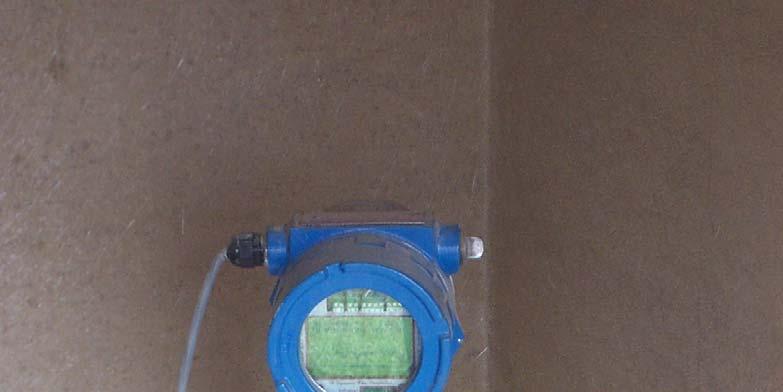
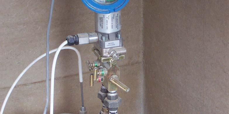
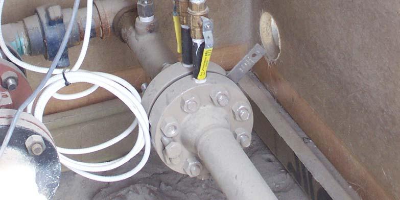
6 DFC Engineering Bulletin

7 DFC Engineering Bulletin

8 DFC Engineering Bulletin
9 CHAPTER 1: Explosion-Proof Installation Drawings
10 DFC Engineering Bulletin
CYCLOPS Z Purge Indicator
 Low cost Simple to install & use Highly reliable & maintenance free Enclosure vent is part of casing Local & remote status indicator Casing available in anodized aluminum & 316 stainless steel 12 or 24
CYCLOPS Z Purge Indicator
 Low cost Simple to install & use Highly reliable & maintenance free Enclosure vent is part of casing Local & remote status indicator Casing available in anodized aluminum & 316 stainless steel 12 or 24
CYCLOPS X Purge Controller XP Version
 Simple to install & use Highly reliable Enclosure purge exhaust vent is part of casing Local & remote status alarms Casing available in anodized aluminum or 316 stainless steel 115 VAC, up to 25 Amps or
CYCLOPS Y Purge Indicator
 Low cost Simple to install & use Highly reliable & maintenance free Enclosure vent is part of casing Local & remote status indicator Casing available in anodized aluminum & 316 stainless steel 12 and 24
STP-MLD. Installation and Owner s Manual
 The Leader in Submersible Technology Mechanical Leak Detector STP-MLD STP-MLD-D STP-MLD-E Gasoline Diesel Flexible Pipe STP-MLD STP-MLD Installation and Owner s Manual 4805 Voges Rd., P.O. Box 139 McFarland,
Rosemount 3095FC MultiVariable Mass Flow Transmitter with MODBUS Protocol
 Quick Installation Guide Rosemount 3095FC Rosemount 3095FC MultiVariable Mass Flow Transmitter with MODBUS Protocol Step 1: Mount the Transmitter Step 2: Connect Wiring Step 3: Set Jumpers and Apply Power
CYCLOPS X Purge Controller SM Version
 Simple to install & use Highly reliable Purge exhaust vent is part of unit enclosure Local & remote status alarms Enclosure is 316 stainless steel 115 VAC up to 25 Amps or 230 VAC up to 12.5 Amps All in
RegFlo TM RF100 Series Pressure and Flow Instruments
 Instruction Manual Form 5661 RF100 Series February 2006 RegFlo TM RF100 Series Pressure and Flow Instruments Contents Specifications.................................. 2 I/O Board Specifications.........................
SMARTLINK METER. Digital Self-checking Thermal Mass Flow Meter
 Flow Control Components - SMARTLINK METER 10-30.9-1 SMARTLINK METER Digital Self-checking Thermal Mass Flow Meter Precise, repeatable mass flow measurement for fuel, air and combustion streams Displays
Model 3051 Sensor Module Replacement
 Model 3051 Sensor Module Replacement 00809-0400-4001 English Rev. BA SAFETY MESSAGES Procedures and instructions in this manual may require special precautions to ensure the safety of the personnel performing
INTERNATIONAL METAL ENGINEERING
 INDICATING TEMPERATURE TRANSMITTER WITH HART 8080HT UNIVERSAL SETTINGS WITH HART PROTOCOL FOR VARIOUS INPUT SIGNALS 2 WIRE TECHNOLOGY, 4 TO 20mA ANALOG OUTPUT HIGH ACCURACY IN TOTAL AMBIENT TEMPERATURE
SMARTLINK METER. Digital Self-checking Thermal Mass Flow Meter
 Flow Control Components - SMARTLINK METER 10-30.9-1 SMARTLINK METER Digital Self-checking Thermal Mass Flow Meter Precise, repeatable mass flow measurement for fuel, air and combustion streams Displays
Rosemount 3095FT MultiVariable Flow Data Logger
 Quick Installation Guide Rosemount 3095FT Rosemount 3095FT MultiVariable Flow Data Logger Step 1: Mount the Transmitter Step 2: Consider Housing Rotation Step 3: Set Jumpers and Switches Step 4: Connect
by Jim Phillips, P. E.
 by Jim Phillips, P. E. Baking flour, coal dust and gasoline; what do these things have in common? They are not the ingredients for a strange new cake recipe. Each of these ingredients is the fuel that
O.K. Safety first CDN USA. Table of Contents. Approvals. Attention IFGC CSA UL ANSI NFPA
 AA...A2 Differential Air Pressure Switch Installation Instructions USA CDN Table of Contents Table of Contents...Page 1 Approvals...Page 1 Attention...Page 1 Specification...Page 2 Model Description &
Series 3730 Electropneumatic Positioner Type
 Series 3730 Electropneumatic Positioner Type 3730-1 Application Single-acting or double-acting positioner for attachment to pneumatic control valves. Self-calibrating, automatic adaptation to valve and
Ignition energy enough for igniting the mixture is available, such as sparkles generated by friction and impaction, electric arc or hot surfaces.
 Elementary knowledge of safety and explosion protection 1.1 Characteristics of explosion A phenomenon, in which substances are converted from one state into another and massive energy and sounds are instantaneously
ATEX/IECEx Coil Manual Type 200 and 300 Series Coils for EH70 Series Solenoid Valves Issue , Released December 13, 2017
 ATEX/IECEx Coil Manual Type 200 and 300 Series Coils for EH70 Series Solenoid Valves Issue 2017.1, Released December 13, 2017 Clark Cooper A Division of Magnatrol Valve Corp. 941 Hamilton avenue Roebling,
Rosemount 4088 MultiVariable Transmitter
 Product Data Sheet May 2015 00813-0100-4088, Rev AC Rosemount 4088 MultiVariable Transmitter With the innovative Rosemount 4088 MultiVariable Transmitter, you can maximize your measurement accuracy and
North American 1599 Electro-Hydraulic Gas Shutoff Valve Bulletin 1599
 Combustion North American 1599 Electro-Hydraulic Gas Shutoff Valve 1599 valves are normally closed safety shutoff valves which are controlled by an electro-hydraulic actuator. 1599 s can be ordered as
Installation, Operation & Maintenance Manual
 IH106 Installation, Operation & Maintenance Manual ZV200 Bypass Valve Model ZV200 Bypass Valve Warning: (1) Periodic inspection and maintenance of Corken products is essential. (2) Inspection, maintenance
Rosemount 4088 MultiVariable Transmitter
 Product Data Sheet January 2018 00813-0100-4088, Rev BA Rosemount 4088 MultiVariable Transmitter With the innovative Rosemount 4088 MultiVariable Transmitter, you can maximize your measurement accuracy
Type 2000 Transducer Product Instructions
 Type 2000 Transducer Product Instructions The Type 2000 is an electro-pneumatic device that regulates an unregulated supply pressure down to an electronically-controlled output pressure. There are two
DuraMAC LIGHT COMMERCIAL & IRRIGATION WATER PRESSURE BOOSTER SYSTEM INSTALLATION INSTRUCTIONS
 DuraMAC LIGHT COMMERCIAL & IRRIGATION WATER PRESSURE BOOSTER SYSTEM INSTALLATION INSTRUCTIONS The DuraMAC TM Water Pressure Booster System is the first booster pump of its kind to be designed for virtually
KENCO ENGINEERING COMPANY
 KENCO ENGINEERING COMPANY P.O. BOX 470426 TULSA, OK 74147-0426 PHONE: (918) 663-4406 FAX: (918) 663-4480 www.kenco-eng.com e-mail: info@kenco-eng.com SERIES KTD THERMAL DIFFERENTIAL FLOW/LEVEL SWITCH INSTALLATION
STP-MLD Installation and Owner s Manual
 STP-MLD Installation and Owner s Manual 2006 400439001 Rev. 6 Franklin Fueling Systems 3760 Marsh Rd. Madison WI 53718 USA Tel: +1 608 838 8786 800 225 9787 Fax: +1 608 838 6433 www.franklinfueling.com
The 285 Annubar Primary Element Series
 The 285 Annubar Primary Element Series www.rosemount.com Rosemount 285 285 Annubar Primary Element Series NOTICE Read this manual before working with the product. For personal and system safety, and for
Instruction manual. Smart Thermal Mass Flow Meter. TYPE : 3000S Series. ientek Co., Ltd.
 Instruction manual Smart Thermal Mass Flow Meter TYPE : 3000S Series ientek Co., Ltd. Factor 2 (P)153-803 Daeryung Technotown 5th #407 493, Gasan-dong Gumcheon-Gu, Seoul, Korea TEL : +82-2-2107-7999 FAX
Petroleum industries are dealing with different hazardous materials starting from storing, processing and distributing the petroleum products These he
 FIRE SAFETY OF PETROLEUM INDUSTRIES By- Debapriya Biswas Additional Director General West Bengal Fire & Emergency Services Petroleum industries are dealing with different hazardous materials starting from
Inline Pressure Control Or Shutoff Valves (Non-digital) And Bypass Pressure Control Or Shutoff Valves (Non-digital)
 And Bypass Pressure Control Or Shutoff Valves (Non-digital)") IN64124 August 15, 1997 Aerospace Group Conveyance Systems Divison Carter Brand Ground Fueling Equipment Applicable additional manuals: Installation Instructions Inline Pressure Control Or Shutoff Valves
IN64124 August 15, 1997 Aerospace Group Conveyance Systems Divison Carter Brand Ground Fueling Equipment Applicable additional manuals: Installation Instructions Inline Pressure Control Or Shutoff Valves
Hazardous Location Enclosures INDEX. Hazardous Location Enclosures HAZ-2
 Hoffman s new ZonEX ATEX-certified enclosures can be used in Zone 1- and Zone 2-rated applications throughout the world. Our NEMA Type 9 enclosures are designed for use in Class II Division 1 and 2 locations
TECHNICAL PAPER 1002 FT. WORTH, TEXAS REPORT X ORDER
 I. REFERENCE: 1 30 [1] Snow Engineering Co. Drawing 80504 Sheet 21, Hydraulic Schematic [2] Snow Engineering Co. Drawing 60445, Sheet 21 Control Logic Flow Chart [3] Snow Engineering Co. Drawing 80577,
CAUTION The sensor must always be completely filled with process media in order to measure accurately.
 SITRANS F Coriolis Flowmeters Quick Start Before installing, including in hazardous areas, refer to the Operating Instructions on the internet or on the SITRANS F literature CD-ROM. They contain detailed
Product Manual. EX40, Version Last Updated: 11/7/16. Product Description:
 Product Manual EX40, Version 2016.1 Last Updated: 11/7/16 Product Description: The EX40 Series encompasses 2-way piloted solenoid valves with a maximum allowable inlet pressure of 15,000 psi [103.4 MPa].
instrument manifolds Instrument Manifolds Index General Purpose Manifolds Overview 1 2 Valve 2 3 Valve 4 5 Valve 6 Mounting kits 8
 Instrument Manifolds Index General Purpose Manifolds Overview 1 2 Valve 2 3 Valve 4 5 Valve 6 Mounting kits 8 Special Application Manifolds Trifold 3 Valve 9 Rotofold 3 Valve 12 Pentafold 5 Valve 15 Mounting
Thermal Mass Flow Meter (Analog)
") Meter (Analog) Precision Fluidics 2 Meters Traditional Analog Flow Meter Parker Meters provide reliable analog flow measurements configured for your process conditions. Each meter offers a linear flow
Meter (Analog) Precision Fluidics 2 Meters Traditional Analog Flow Meter Parker Meters provide reliable analog flow measurements configured for your process conditions. Each meter offers a linear flow
Installation and Maintenance Instructions 44TA Liquid Level Float Switch
 OPW Installation, Operation and Maintenance Manual, Page 54 MPORTANT: Please read these warnings and use the assembly instructions completely and carefully before starting. Failure to do so may cause product
F-4600 INLINE ULTRASONIC FLOW METER Installation and Operation Guide
 F-4600 INLINE ULTRASONIC FLOW METER Installation and Operation Guide 11451 Belcher Road South, Largo, FL 33773 USA Tel +1 (727) 447-6140 Fax +1 (727) 442-5699 1054-7 / 34405 www.onicon.com sales@onicon.com
Low Profile Insertion Vortex
 Low Profile Insertion Vortex Product Features The same insertion meter can measure Steam, Gases or Liquids. Standardize on an insertion bar that can measure line sizes 2 24 Heavy Duty & Maintenance Free
ELECTRICAL INSTALLATION
 ENCLOSURE DIMENSIONS NOTES (3) 3/4" NPT WALL MOUNT BRACKET, (2) 5/16" DIA. THRU - HARDWARE IS CUSTOMER SUPPLIED 1¼" NPT AUTO-TEST OPTION 6.312" 160.3 mm 4.85" 123 mm 3.90" 99 mm 4.95" 126 mm 4.85" 123
BULLETIN NO.ELEC IM121/10A Replaces IM121/09A
 Mid-West Instrument BULLETIN NO.ELEC IM121/10A Replaces IM121/09A INSPECTION Model 121 Indicating Differential Pressure Switch / Transmitter Electrical: Installation and Operating Instructions Upon receipt
High Pressure Solenoid Valves
 High Pressure Solenoid Valves Available for Quick Delivery Controls the flow of Gases & Liquids up to 15,000 PSIG Natural Gas, Hydrogen & other High Pressure Gases High Pressure Cryogenics Flammable Liquids
Rosemount 3051CFA Annubar Flowmeter
 December 2013 Rosemount 3051 Rosemount 3051CFA Annubar Flowmeter The Rosemount 3051CFA Annubar Flowmeter utilizes the patented T-shaped sensor design that delivers best in class accuracy and performance.
Figure 1: WPR2 Dimensions and Hardware
 Installation and Operation Instructions WPR2 Series (Max. Line Pressure < 300 PSI) Wet to Wet Differential Pressure Ø0.200" 2.60" 4.47" 5.47" 5.28" 3.00" Precautions Figure 1: WPR2 Dimensions and Hardware
PF 3100 ION PILOT CARD PRO.FIRE
 PF 3100 ION PILOT CARD www.profireenergy.com 1.855.PRO.FIRE 1 TABLE OF CONTENTS PF3100 ION PILOT CARD INFORMATION GUIDE INTRODUCTION... 4 1.1 Functional Description.... 4 1.2 System Requirements.... 4
Manifold & Gauge Valves I [
 Instrument High Technology Valve, Flange & Fitting Series Manifold & Gauge Valves I [ Instrument Manifolds Stainless steel Bar handle Packing bolt permits stem packing adjustment. Stem thread enhance cycle
MEASUREMENT SOLUTIONS FOR THE OIL & GAS INDUSTRY
 MEASUREMENT SOLUTIONS FOR THE OIL & GAS INDUSTRY WELL SERVICING UPSTREAM MIDSTREAM DOWNSTREAM OFFSHORE Our broad offering of instrumentation for the oil & gas industry addresses applications including:
2 Fluid Level Management
 2 Fluid Level Management Introduction.................................... 2-3 REN Oil Level Regulator........................ 2-5 REN Slow Flow Meter.......................... 2-9 Slow Flow Meter Remote
IFOA Integral Flow Orifice Assembly
 Instruction MI 022-333 July 2007 Introduction IFOA Integral Flow Orifice Assembly The IFOA integral flow orifice assembly is used in conjunction with a Foxboro electronic or pneumatic differential pressure
SR100 Series Service Regulators. Technical Bulletin
 SR100 Series Service Regulators Technical Bulletin Model SR100 Series Regulator 02 Elster American Meter The compact, high capacity SR113 service regulator is designed for residential or light commercial/industrial
STP-MLD+ Installation and Owner s Manual. Manual # Revision Date Changes from previous revision
 STP-MLD+ Installation and Owner s Manual Manual # Revision Date Changes from previous revision 400439002 3 Sept. 2014 Changed MLD+AG description to 85% ethanol Franklin Fueling Systems 3760 Marsh Rd. Madison,
SPECIAL SPECIFICATION 8676 Solar Panel Power Supply System
 2004 Specifications CSJ 2552-01-033 SPECIAL SPECIFICATION 8676 Solar Panel Power Supply System 1. Description. This work shall consist of furnishing and installing an integrated Solar Panel Power Supply
Weather-Proof Thermal Mass Flow Meter for Pipe - Duct
 MF200A Series Weather-Proof Thermal Mass Flow Meter for Pipe - Duct Feature & Application n Accuracy ±1.0% reading n Watch-dog software n Wide turn-down ratio 300 : 1 n Repeatability ±0.15% FS n 16 x 2
The installation and maintenance of this product must be done under the supervision of an experienced
 AA...A2 Differential Air Pressure Switch Installation Instructions USA CDN Table of Contents Table of Contents...Page 1 Approvals...Page 1 Attention...Page 1 Specification...Page 2 Model Description &
Hand & Gauge Isolation Valves Needle Valves Gauge Valves Block & Bleed Valves. Manifolds
 Hand & Gauge Isolation Valves Needle Valves Gauge Valves Block & Bleed Valves Manifolds Two, Three & Five Valve Manifolds for Gauge and Differential Pressure Applications Accessories Built Hex tough for
Instrumentation Manifold Valves
 Instrumentation Manifold Valves SM2V / SM3V / SM5V Series Ordering Information Example : SM2 V - F 8N - M40 1 2 3 4 5 1. Valve Series 2. Mounting Type 3. End Connection Type SM2 : 2-Valve Manifolds SM3
Evaporative Emissions
 Page 1 of 6 Published : Apr 8, 2005 Evaporative Emissions 4.4L V8 Evaporative Emissions Component Layout Item Part Number 1 - Fuel filler head 2 - DMTL pump filter (NAS only) 3 - Fuel tank vent hose to
Hand & Gauge Isolation Valves Needle Valves Gauge Valves Block & Bleed Valves. Manifolds
 Hand & Gauge Isolation Valves Needle Valves Gauge Valves Block & Bleed Valves Manifolds Two, Three & Five Valve Manifolds for Gauge and Differential Pressure Applications Accessories Built Hex tough for
Rosemount 3051S Electronic Remote Sensor (ERS) System
 System") Rosemount 3051S Electronic Remote Sensor (ERS) System The Rosemount 3051S ERS System is a flexible, 2-wire 4-20 ma ART architecture that calculates differential pressure (DP) electronically using two pressure
Rosemount 3051S Electronic Remote Sensor (ERS) System The Rosemount 3051S ERS System is a flexible, 2-wire 4-20 ma ART architecture that calculates differential pressure (DP) electronically using two pressure
VAREC 5910B AND 5920B SERIES RELIEF VALVE WITH FLAME ARRESTER
 These units combine the high flow capacity of a pressure and vacuum relief valve with an easy-to-maintain flame arrester for maximum protection and reliable operation FEATURES 5920B Oversized pressure
Model 5000 Level Controller
 Features Multiple Configurations The 5000 level controller is easily configured for either reverse or direct actions for both pneumatic and electric pilot options. The pneumatic pilot is available in snap
Installation Operation Maintenance ADDENDUM BULLETIN No. PS-IOM-HYP-0203-H
 Installation Operation Maintenance ADDENDUM BULLETIN No. PS-IOM-HYP-0203-H USER NOTE: This addendum serves as additional information for Pulsafeeder PULSAR and PULSAR Shadow metering pumps equipped with
Pneumatic Isolation Module
 Pneumatic Isolation Module (Cat. 2030-Pxxxxx) ATTENTION: Hazardous Voltage or other forms of energy could be present. To avoid serious injury or death: Prior to beginning the installation and wiring process,
Model CO Compact Orifice for use with Foxboro Differential Pressure Transmitters
 Product Specifications Model CO Compact Orifice for use with Foxboro Differential Pressure Transmitters PSS 3-5A1 E MODEL CO WITH TRADITIONAL STRUCTURE MODEL CO WITH LOW PROFILE STRUCTURE (LP1) MODEL CO
METAL VAREA-METER STRAIGHT THROUGH TYPE ROTAMETER
 TECHNICAL INFORMATION METAL VAREA-METER STRAIGHT THROUGH TYPE ROTAMETER Electronic Transmitter INTRODUCING THE METAL TUBE VAREA-METER U.S. Filter/Wallace & Tiernan Products straight through metal tube
Venting valves. Valves. Manually actuated. Venting valves. Installation elements
 Installation elements Venting Manually actuated Venting For manually venting small vacuum chambers Valve opens and closes easily by loosening/ tightening the screw cap FVB = Venting valve HA = Manually
Mid-West Instrument. Series 700 "Wet/Wet" Installation and Operating Instructions. Differential Pressure Transmitter
 Mid-West Instrument IM_700/A Series 700 "Wet/Wet" Installation and Operating Instructions Differential Pressure Transmitter 6500 Dobry Dr. Sterling Heights, MI USA Toll Free: 800-648-5778 Ph 586-254-6500
Product Data Sheet , Rev GA Catalog Content
 HIGHLY ACCURATE SMALL-BORE FLOW MEASUREMENT CAPABILITY WITH MINIMAL INSTALLATION AND MAINTENANCE REQUIREMENTS Improves accuracy and repeatability in 1 /2-in., 1-in., and 1 1 /2-in. line sizes Reduces leak
Solutions beyond products...
 ORIGINAL INSTRUCTIONS IH102C Installation, Operation & Maintenance Manual Model B177 External Automatic Bypass Valve Model B177 External Automatic Bypass Valve Warning: (1) Periodic inspection and maintenance
SynergEX Panelboards for Hazardous Locations
 SynergEX Panelboards for Hazardous Locations Installation & Maintenance Information 1. APPLICATION SynergEX panelboards provide short circuit protection for feeder or branch circuits to control lighting,
ABB MEASUREMENT & ANALYTICS DATA SHEET. AV1 and AV2 Characterizable pneumatic and electro-pneumatic positioners
 ABB MEASUREMENT & ANALYTICS DATA SHEET AV1 and AV2 Characterizable pneumatic and electro-pneumatic positioners 2 AV 1 AN D AV 2 CH AR ACTER I Z ABLE PNE U MATIC POSITIONE RS DS/AV 1 2-E N RE V. I Measurement
Output signal active note. Measuring range rel. pressure. Electrical Data Power supply DC V, ±10%, 1.1 W
 Differential Pressure Sensor (Air) Differential pressure transmitter with 8 selectable ranges and outputs 0 to 5/10 V or 4 to 20 ma. NEMA 4X / IP65 rated enclosure. For monitoring the differential pressure
MPD Manifold 4 x psi with Integrated Control System and Coriolis Flowmeter
 MPD Manifold 4 x 6 2000psi with Integrated Control System and Coriolis Flowmeter The MTC Managed Pressure Drilling (MPD) manifold has been designed to automatically maintain the annulus surface back pressure
Installing an Auxiliary Pressure Control Module
 Installing an Auxiliary Pressure Control Module Agilent 6850 GCs Accessory G3349B These instructions are divided into two parts: Part 1 to prepare the Auxiliary Electronic Pressure Control ("AuxEPC") module
SECTION HVAC POWER VENTILATORS
 SECTION 233423 HVAC POWER VENTILATORS 1. PART 1 GENERAL 1.1. RELATED DOCUMENTS A. Drawings and general provisions of the Contract, including General and Supplementary Conditions and Division 01 Specification
SKINNER Intrinsically Safe Series Four-Way
 SKINNER Four-Way Two-Position Valves SPECIFICATIONS Mechanical Characteristics Standard Materials of Body Aluminum Seals FKM, NBR. Other diaphragm materials available upon request. Compatible Fluids Air
BLACKMER BYPASS VALVES
 BLACKMER BYPASS VALVES INSTALLATION OPERATION AND MAINTENANCE INSTRUCTIONS EBSRAY MODEL: RV18 RV18CBS2, RV18CBS3, RV18VRS10, RV18VRS14, RV18VRS19 967020 INSTRUCTIONS NO. 551-E00 Section Effective Replaces
Switches for Pressure to 8000 psig, Vacuum, Differential, or Level Control with General Purpose, Watertight or Explosion-Proof Enclosures
 S-SERIES Pressure Switches Switches for Pressure to 8000 psig, Vacuum, Differential, or Level Control with, or s Features: Set point repeatability, +1% of operating range. All wiring terminals, adjustments
Smart Pressure Transmitter
 DOC. NO.: C3100L-E16B Smart Pressure Transmitter with Diaphragm Seal MODEL APT3100L DUON System Co., Ltd. 298-29, GONDAN-RO, GUNPO-SI, GYEONGGI-DO, KOREA 15809 Tel : +82-31-3-6100 Fax : +82-31-29-7200
B21 Series BASOTROL Gas Valve
 Installation Instructions B21 Issue Date September 19, 2017 Installation IMPORTANT: These instructions are intended as a guide for qualified personnel installing or servicing BASO Gas Products. Carefully
The use of batteries in hazardous areas. 1. Type of batteries and technical evolution. March 2018
 March 2018 1. Type of batteries and technical evolution The use of batteries in hazardous areas The electric energy in alternating current produced by thermal systems (coal-fired or oil power stations
Hot Tap Insertion Vortex
 Hot Tap Insertion Vortex Product Features The same insertion meter can measure Steam, Gases or Liquids. Standardize on an insertion bar that can measure line sizes 2 48 Heavy Duty & Maintenance Free Design
1000 Series Piston Type Differential Pressure Gauges
 1000 Series Piston Type Differential Pressure Gauges 1. Safety Before installing, check the Series Number and verify compatibility to the process media and temperature in contact with the wetted parts.
Rosemount 1195 Integral Orifice Primary Element
 September 2014 Rosemount DP Flow Rosemount 1195 Integral Orifice Primary Element Rosemount 1195 Integral Orifice Primary Element utilizes a self centering orifice plate design to eliminate installation
Diesel Engine Shutdown System
 Diesel Engine Shutdown System Models CSX-300, 310 CSX-301, 311 Typical applications Marine engine safety Petrochemical industry safety Vacuum trucks Cranes - both engines Land drilling rigs Offshore equipment
SECTION CENTRIFUGAL HVAC FANS
 SECTION 233416 - CENTRIFUGAL HVAC FANS 1. PART 1 GENERAL 1.1. RELATED DOCUMENTS A. Drawings and general provisions of the Contract, including General and Supplementary Conditions and Division 01 Specification
Instruction Manual. DMF-1-Series Coriolis Mass Flow Meter
 1 京制 01050054 号 Instruction Manual DMF-1-Series Coriolis Mass Flow Meter Beijing Sincerity Automatic Equipment Co., LTD Tel: +86(010)52073959/ 52073956 18600270515 2 NOTICE We thank you very much for your
Instrument Valves and Manifolds
 Instrument Valves and Manifolds Needle Valves Instrument Valve Orifice Block Valves Gauge Block Valves Block & Bleed Valves Integral Block & Bleed Valves Two Valve Manifolds Three Valve Manifolds Five
Design and Application Details
 LO-NOX Line Burners Page 5803 Design and Application Details Total heat release and LO-NOX Burner footage are normally selected from the tables given in the Series HG Mixing Tube section of the Maxon catalog
Gas Conversion Kits and Instructions
 General and Warnings FOR YOUR SAFETY WHAT TO DO IF YOU SMELL GAS Do not try to light any appliance. Do not touch any electrical switch; do not use any phone in your building. Leave the building immediately.
Rosemount 485 Annubar Flanged Assembly
 Quick Installation Guide 00825-0100-809, Rev DB Flanged 85 Annubar Rosemount 85 Annubar Flanged Assembly Start Step 1: Location and Orientation Step 2: Drill Holes into Pipe Step 3: Assemble and Check
NV Direct Coupled Globe Valve Actuator
 70396 Rev. C Non-spring return, on/off, floating point, proportional control NV Direct Coupled Globe Valve Actuator NV24-3 US NVD24-3 US NV24-MFT US NVD24-MFT US Application For on/off, floating point
Installation, Operation, and Maintenance Manual
 Intelligent Flow Measurement Your Sole Source for Badger Differential Producers Worldwide 6 Blackstone Valley Place, Lincoln RI 02865-1162 Ph: 401 334 1170 Fx: 401 334 1173 Em: solutions@wyattflow. Installation,
NC State University Design and Construction Guidelines Division 23 Energy Management
 1.1 Purpose A. The following guidelines provide the methodology and requirements to assure that designs meet NC State standards for campus utility metering. 2.1 General Requirements A. Meters shall have
VAREA-METER FLOW MEASUREMENT BY-PASS TYPES
 TECHNICAL INFORMATION VAREA-METER FLOW MEASUREMENT BY-PASS TYPES US Filter Wallace & Tiernan Products By-Pass Varea-Meter can measure high volume flows through any pipeline that can be equipped with a
Easytork Solenoid Valve IOM
 Easytork Solenoid Valve IOM General This installation document is to be read in conjunction with the Easytork Vane Actuator IOM. Description The Easytork Solenoid Valve ( ESV ) series is intended for the
System Electropneumatic Converters (Proportional Valves) Electronic Process Controllers Signal Converters
 Electronic Process Controllers Signal Converters") System 6000 Electropneumatic Converters (Proportional Valves) Electronic Process Controllers Signal Converters Edition April 2018 Information Sheet T 6000 EN Electropneumatic Converters i/p converters
System 6000 Electropneumatic Converters (Proportional Valves) Electronic Process Controllers Signal Converters Edition April 2018 Information Sheet T 6000 EN Electropneumatic Converters i/p converters
Rosemount 3051S Series of Instrumentation
 Product Data Sheet January 2013 00813-0100-4801, Rev RA Rosemount 3051S Series of Instrumentation Scalable Pressure, Flow, and Level Solutions Innovation Reaching Across Your Operation With the Rosemount
AKRON ELECTRIC, INC. CONDUIT PRODUCTS GR SERIES... EYS SERIES... TU SERIES... XBD-50 SERIES...
 CONDUIT PRODUCTS F GR SERIES... EYS SERIES... TU SERIES... XBD-50 SERIES... 1025 Eagon St. Barberton, Ohio 44203 Ph:(330) 745-8891 Fax:(330) 745-2504 Toll Free:(800)-275-2535 06/09/03 NEW PRODUCT IN STOCK
Hydro-Flow Model 3100
 Hydro-Flow Model 3100 Installation and Operation Guide installation and operation guide Contents: Understanding Your Flow Meter... 1 Identifying Your Flow Meter...2 Installing Your Flow Meter...3,4 Making