BRAKE SYSTEM FUNDAMENTALS KARAN BHARDIYA ASSISTANT MANAGER -R&D ENDURANCE TECHNOLOGIES PVT.LTD. DISC BRAKES
|
|
|
- Gervase Lee
- 6 years ago
- Views:
Transcription


1 BRAKE SYSTEM FUNDAMENTALS KARAN BHARDIYA ASSISTANT MANAGER -R&D ENDURANCE TECHNOLOGIES PVT.LTD. DISC BRAKES
2 AUTOMOTIVE BRAKING SYSTEMS How brakes manufacturing industry is different then rest of the automotive industries????
3 3 HOW IT WORKS Friction develops heat which absorbs kinetic energy of the car
4 4 PURPOSE OF BRAKING SYSTEM Stop the vehicle by converting the kinetic energy of the vehicle to heat energy. Heat energy is created in the brakes by friction. Friction is created between a moving and a non-moving surface at each wheel to generate the heat. Disc and drum brakes are the most common type of braking systems used.
5 5 FACTORS EFFECTING BRAKING* Number of wheels braking. Tire traction. Weight of vehicle. Road surface. Type of friction material. Load transfer. Surface area of friction material. Incline or decline of road. (gravity) Size or discs or drums Engine braking. Pressure applied

6 6 TYPES OF BRAKING SYSTEMS Service brakes. It s the primary braking system using a the pedal connected to a hydraulic system causing it to operate. Parking brakes. It s mechanically applied by a lever or pedal.

7 TYPICAL SYSTEM (NO ABS)
")
8 TYPICAL LAYOUT OF SYSTEM (WITH ABS)
9 COMPONENTS
10 ELEMENTS OF DISC BRAKE There are major four elements of brake disc 1. Master Cylinder usually accessible by user & is a actuating device. 2. Brake Caliper - is the end part of effort transmission in brakes which retards the motion of two wheeler 3. Hose is for transmission of Oil from Master Cylinder to Brake caliper 4. Brake Disc mounted on wheel & is major part in braking action & absorbing the braking energy.

11 Principle: WORKING OF MASTER CYLINDER Master cylinder works on principle of pumping of incompressible fluids, in which the pressure is applied on Brake Fluid/oil which then transferred to caliper for actuation of brake pads.
12 WORKING OF MASTER CYLINDER The feed aperture ( 0.5 mm Micro hole ) and compensation hole are open and connect the pressure chamber and compensation enclosure to reservoir. A small quantity of fluid returns from pressure chamber to reservoir before primary seal completely blocks the feed aperture Once this condition is achieved, any force exerted on the lever is transformed into pressure in the brake circuit.
13 When the brake lever is released, the piston is pressed back quickly by the return spring to its own position. Due to this, a vacuum is generated in the pressure chamber and the fluid in the compensation chamber flows to pressure chamber past the primary seal, due to its flexible lip edges which allow the brake fluid to pass to pressure chamber.


14 TANDEM MASTER CYLINDER ASSEMBLY


15 TANDEM MASTER CYLINDER ASSEMBLY
16 MASTER CYLINDER ASSEMBLY NEVER ALLOW MINERAL OIL TO COME IN CONTACT WITH SEALS OR OTHER RUBBER PARTS OF DISC BRAKE, SINCE IT WILL CAUSE DAMAGE TO THESE PARTS FREE PLAY AT THE END OF THE LEVER IS PROVIDED TO ENSURE THAT IN THE FREE CONDITION, THE PISTON DOES NOT REMAIN IN THE PUSHED CONDITION. THIS ENSURES THAT THERE IS NO PRESSURE IN THE SYSTEM WHEN THE BRAKE IS NOT APPLIED.

17 WORKING OF CALIPER Principle Caliper assembly converts the hydraulic pressure generated in the master cylinder into gripping force on the rotating brake disc & retards the rotation of disc.

18 lug nuts DISC BRAKE SYSTEM Hydraulic pressure transmitted via brake lines and hoses to piston(s) at each brake caliper. Pistons operate on friction pads to provide clamping force Rotors are free to rotate due to wheel bearings and ubs that contain them The hub and hubless rotors. Hub can be part of brake rotor or separate assembly that the rotor slips over and is bolted to by the

19 WORKING OF HYDRAULIC BRAKE CALIPER (SINGLE ACTING FLOATING TYPE) In the brake released condition, the brake fluid inside the caliper is at atmospheric pressure and the disc rotates freely as the pads do not press against it. When the brake lever is operated, the pressure generated in the hydraulic circuit acts on the caliper pistons. The caliper pistons in turn push the friction pad on the side of the caliper body against the rotating disc.
20 WORKING OF HYDRAULIC BRAKE CALIPER (SINGLE ACTING FLOATING TYPE) CONTD. The friction pad on the other side of the disc also presses against the disc due to reaction force on caliper body. Thus both the friction pads press against the disc, thereby generating braking torque & retards the wheel motion.


21 DISC BRAKE SYSTEM Square cut O-ring. A. Square cut O-ring during brake application. B. Square cut O-ring during brake release.

22 WORKING OF CALIPER AT GLANCE
 Caliper mounting")
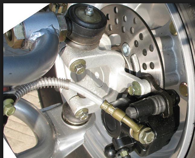
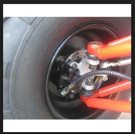
23 DISC BRAKE SYSTEM The brake caliper assembly is normally Bolted to vehicle axle housing (steering knuckle) Caliper mounting methods.

24 DISC BRAKE SYSTEM Two types of calipers: fixed and sliding/floating


25 DISC BRAKE SYSTEM FixedType Brake System Applies two pistons to opposite sides of rotor Caliper stays stationary Disc Brakes require higher hydraulic pressure

26 DISC BRAKE SYSTEM When the brakes are applied, hydraulic pressure forces the piston toward the rotor. Floating Type Brake System Takes up any clearance Pushes pad into rotor brake pads, applying brakes. Sliding/floating caliper application.

27 DISC BRAKE SYSTEM tsquare cut O-ring seals piston in disc brake calipers. Compressed between piston and caliper housing Keeps high-pressure brake fluid from leaking Prevents air from being drawn into system O-ring and O-ring cut to show square section. groove in caliper. B. Square cut O-r


28 DISC BRAKE SYSTEM Although the phenolic pistons themselves do not corrode, the cast iron bore of the caliper does corrode and rust Can cause a phenolic piston to seize in the bore Phenolic pistons transfer heat slower than steel pistons Helps prevent boiling of the brake fluid
29 DISC BRAKE SYSTEM APPLY SILICONE GREASE ON SECONDARY PIN SLIDING SURFACE APPLY LOCTITE TO SECONDARY PIN THREADS BEFORE ASSY NEVER ALLOW MINERAL OIL TO COME IN CONTACT WITH SEALS OR OTHER RUBBER PARTS OF DISC BRAKE, SINCE IT WILL CAUSE DAMAGE TO THESE PARTS

30 BRAKE FRICTION MATERIALS Five Characteristics Resist Fading with increased temp Resist fading when wet Recover quickly Wear gradually Quiet Disc brake pads consist of friction material bonded or riveted onto steel backing plates.
31 LINING MATERIAL Non-metallic Made from synthetic fibers (used to be asbestos) Semi-metallic Made from iron and synthetic fibers More fade resistant - harder pad More prone to squealing Full-metallic Made from sintered metals Very hard pad

32 DISC BRAKE PADS AND FRICTION MATERIALS Composition of friction material affects brake operation Materials that provide good braking with low pedal pressures tend to lose efficiency when hot Wear out quicker Materials that maintain stable friction coefficient over a wide temperature range Generally require higher pedal pressures Tend to put added wear on disc brake rotor
33 DISC BRAKE SYSTEM Advantages Greater amounts of heat to atmosphere Cooling more rapid Rotors scrape off water more efficiently Self-adjusting Don t need periodic maintenance Easier to service
34 DISC BRAKE SYSTEM Disadvantages Prone to noise (squeals and squeaks) Rotors warp easier Not self-energizing Hard to use as parking brakes

35 BRAKE PLUMBING AUTO RICKSHAW S FRONT TUBE IS BEST FOR COUPLING Rigid steel brake lines are double wall Flexible hoses connect rigid lines on vehicle to each wheel Transmits hydraulic fluid to each wheel
36 RearBrakePresure PROPORTIONING VALVES Reduce the pressure to TYPICALPROPVALVEPERFORMANCECURVE 80 the rear brakes Diagonal systems require two Split Point Slope Split and slope are changed to create proper balance Hard Stops ,0 FrontBrakePresure
37 DRUM BRAKE SYSTEM F = ma


38 WHEEL CYLINDER Wheel cylinder or caliper pistons are slave cylinders Change hydraulic pressure back into mechanical force Can use one or two cylinders at each wheel

39 POWER ASSIST INCREASES FORCE OF DRIVER S FOOT

40 CABLE PARKING BRAKE Parking or Emergency Brake

41 PARKING BRAKE SYSTEMS Foot or Hand Brake Are cable controlled Several Styles As shown Drum in hat Driveline
42 BRAKE SYSTEM ENERGY


43 BRAKE SYSTEM PRINCIPLES Kinetic Energy Mass Weight Speed Inertia and Momentum

44 FRICTION PRINCIPLES Kinetic and Static Friction Friction and Pressure Friction and Surface Area Coefficient of Friction Brake Fade
45 BRAKING DYNAMICS Weight Transfer Weight Distribution Braking Power Friction Efficiency Brake to Wheel Wheel to Road Surface Traction Efficiency Skidding
46 HYDRAULIC PRINCIPLES Fluids cannot be compressed Fluids can transmit Movement Acts Like a steel rod in a closed container Master cylinder transmits fluid to wheel cylinder or caliper piston bore. Fluids can transmit and increase force The area of the piston is determined by using the formula 3.14 X R 2
47 HYDRAULIC PRESSURE IS DISTRIBUTED EQUALLY IN ALL DIRECTIONS
48 THE APPLIED FORCE CAN BE CHANGED BY CHANGING THE PISTON SIZE. F = PXA F A
49 ADVANTAGE BY HYDRAULICS F = ma & F = pa

50 BRAKE PEDAL DESIGN Output to master cylinder 400 N and 36 mm 4:1 Nominal Pedal Ratio First Mechanical Advantage is Driver s foot Length of Lever determines force applied Uses Fulcrum Pedal Ratio Driver Input 100 N and 144 mm 50

51 BRAKE FORCE AT REAR STEPS TO BE FOLLOWED DURING DESIGNING Packaging constraints Avaibility in the market Design requirements BRAKE FORCE DISTRIBUTION DIAGRAM UNLADEN CONDITION LADEN CONDITION BRAKE FORCE AT FRONT
52 PACKAGING CONSTRAINTS
53 VEHICLE DATA REQUIRED FOR CALCULATIONS GVW -Laden Front Axle weight (Kg) if provided Calculated Rear Axle weight (Kg) Wheel base "e" (m) 1.49 GVW (Kg) C.G. "h" (m) Mechanical efficiency 0.9 Hydraulic efficiency 0.9 front Pedal ratio 4.5 Caliper Piston dia (cm) Number Of Pistons 2 Area (cm2) 12 Effective radius (m) Master dia (cm) 1.92 Master Piston Area(cm2) 1.13 Mue 0.37 Static Rolling radius (m) 0.291


54 FINDING THE C.G OF THE VEHICLE??

55 IS : 1989 & ONLINE STUFFS
56 FIND THE LOAD TRANSFER FROM THE VEHCILE DATA Dynamic load transfer in laden G condition : STEP :1 = {GVWx --Gx Height of C.G from ground in laden condition} wheel base Dynamic load transfer in laden condition on front Axle ---G conditions: =Front axle weight in laden condition +{ Dynamic load transfer in laden ---G condition} STEP :2 Braking force in laden condition on front Axle conditions: = --G x{dynamic load transfer in laden condition on front G in laden condition} STEP :3 The braking torque on front --- G in laden condition : = braking force on front in laded condition x{front tyre dynamic rolling radius } STEP :4
57 FIND THE LOAD TRANSFER FROM THE VEHCILE DATA Dynamic load transfer in laden condition on Rear Axle G conditions: RAW {dynamic load transfer in unladen condition} STEP } :5 Thus the braking force at in laden condition =--Gx{load transfer at Rear in unladen condition} STEP :6 The braking torque on Rear in unladen condition : = braking force on Rear in unladen condition x{rear tyre dynamic rolling radius } STEP :7 This is the minimum requirements of the vehicle as per wheight and C.G of the vehicle.
58 DIMENSIONS OF CALIPERS TO SUIT THE DESIRED CONFIGARATIONS OF THE VEHICLE: Diameter of caliper piston= ----mm Area of caliper piston = mm2 Coefficient of friction of the pad (mue) = 0.37 Disc outer diameter = 200mm ( based on market survey and packaging ) Effective radius of the disc is ( radius of the disc - half the width of the brake pad +1mm) =87mm Dynamic tire radius of the front wheel (r)= mm
59 OUT PUT OF THE DESIGN 0.6G & 1G MAX LINE PRESSURE = PEDAL EFFORT X PEDAL RATIO X 0.9 ( hydraulic losses) M.C AREA BRAKING FORCE FRONT = (LINE PRESSURE X CALIPER AREA X EFFECTIVE RADUIS X MUE X 2 ) FRONT DYNAMIC ROLLING RADIUS BRAKING TORQUE= BRAKING FORCE FRONT X FRONT DYNAMIC ROLLING RADIUS UNLADEN WHEEL UNLOCKED DECELERATION = BRAKING FORCE FRONT TARGET IS 0.6G K.V.W LADEN WHEEL UNLOCKED DECELERATION = BRAKING FORCE FRONT TARGET IS 0.6G G.V.W
60 CONCLUSION : Finally the results of BRAKING FORCE FRONT = (LINE PRESSURE X CALIPER AREA X EFFECTIVE RADUIS X MUE X 2 ) shall be greater then FRONT DYNAMIC ROLLING RADIUS > Braking force in laden condition on front Axle conditions: = --G x{dynamic load transfer in laden condition on front G in laden condition}


61 SUGGESTIONS : MASTER CYLINDER. GO AHEAD WITH T.M.C OF REGULAR SIZE 19.2 MM BORE BUNDY TUBES- Metallic tubes are easily available in the market cut & braze it as per requirements BRAKE CALIPER Most of the calipers available in the market are 28 x2 diameter use it for rear Use 30 dia single piston front Hose Bajaj Auto s front hose should we chosen. Easily mates with the Bundy tube end. BRAKE DISC try to fit the Max possible dia of the disc based on the packaging constraints


62 A designer knows he has achieved perfection not when there is nothing left to add, but when there is nothing more to take away THANK YOU
Brake System Operation
 Brake System Brake System Operation Donald Jones Brookhaven College Master cylinder Brake lines Hydraulic valves Disc brakes Drum brakes Power assist unit Parking brake Antilock system Brake System Functions
Chapter 33 Fundamentals of Hydraulic and Air-Over-Hydraulic Braking Systems
 Chapter 33 Fundamentals of Hydraulic and Air-Over-Hydraulic Braking Systems Introduction Vehicle s braking system must meet the following requirements: To adequately and safely reduce a vehicle s speed,
C. Brake pads Replaceable friction surfaces that are forced against the rotor by the caliper piston.
 BRAKES UNIT 1: INTRODUCTION TO BRAKE SYSTEMS LESSON 1: FUNDAMENTAL PRINCIPLES OF BRAKE SYSTEMS I. Terms and definitions A. Brake fading Loss of brakes, usually due to heat. B. Brake lining Material mounted
MASTER CYLINDER. Section 2. Lesson Objectives
 MASTER CYLINDER Lesson Objectives 1. Explain the difference between conventional and diagonal split piping system and their application. 2. Describe the function of the compensating port of the master
DESCRIPTION & OPERATION
 DESCRIPTION & OPERATION BRAKE BOOSTER Delco-Moraine Single Diaphragm A combined vacuum-hydraulic unit which uses a combination of intake manifold vacuum and atmospheric pressure to provide power assist.
Brake Systems. Introduction
 Brake Systems Figure 1. A Typical Brake System Introduction The brake system (Figure 1) is designed to slow and halt the motion of a vehicle. To do that, various components within a hydraulic brake system
DISC BRAKES. Section 4. Components and Operation of Disc Brakes. Disc Brake Assembly
 DISC BRAKES Components and Operation of Disc Brakes A disc brake assembly consists of a: cast iron disc (disc rotor) that rotates with the wheel. caliper assembly attached to the steering knuckle. friction
Modern Auto Tech Study Guide Chapters 71 & 73 Pages Brake Systems 49 Points. Automotive Service
 Modern Auto Tech Study Guide Chapters 71 & 73 Pages 1369 1444 Brake Systems 49 Points 1. Automotive systems use to stop, slow or to hold the wheels from turning. Brake, Friction Brake, Fraction Brake,
DEVELOPMENT OF HYDRAULIC BRAKE DESIGN SYSTEM APPLICATION
 DEVELOPMENT OF HYDRAULIC BRAKE DESIGN SYSTEM APPLICATION AMOGH DESHPANDE Department of Mechanical Engineering, VJTI, Matunga, Mumbai, India ABSTRACT The brakes which are actuated by the hydraulic pressure
Brake System Fundamentals Chapter 71 Name Date Period
 Brake System Fundamentals Chapter 71 Name Date Period Basic Brake System Matching 1. Metal tubing and rubber hose that transmit pressure to the wheel brake assemblies. 2. Mechanical system for applying
FUNDAMENTAL PRINCIPLES
 FUNDAMENTAL PRINCIPLES Fundamental Principles The most important safety feature of an automobile is its brake system. The ability of a braking system to provide safe, repeatable stopping is the key to
Self Adjusting Disc Brakes
 Disc Brakes Four advantages of Disc Brakes to Drum Brakes 1) Resistance to heat fade 2) Resistance to water fade 3) Less of a tendency to pull 4) Automatically adjust to lining wear Self Adjusting Disc
DESIGN, ANALYSIS AND FABRICATION OF BRAKING SYSTEM WITH REAR INBOARD BRAKES IN BAJA ATV
 DESIGN, ANALYSIS AND FABRICATION OF BRAKING SYSTEM WITH REAR INBOARD BRAKES IN BAJA ATV Aman Sharma 1, Prakhar Amrute 2, Suryakant Singh Thakur 3, Jatin Shrivastav 4 1,2,3,4Department of Mechanical Engineering,
FUNDAMENTAL PRINCIPLES
 Section 1 FUNDAMENTAL PRINCIPLES Lesson Objectives 1. Describe the cycle of heat as it applies to automotive brakes. 2. Explain the effect of heat transfer as it relates to brake fade. 3. Describe how
Braking System Layout
 The Braking System The energy used to accelerate or move a vehicle from rest to a certain speed is called Kinetic i (moving) energy. To slow the vehicle down, this kinetic energy must be converted or changed,
Module 11: Antilock Brakes Systems
 ÂÂ ABS Brake System Antilock Brake System Operation Principles of ABS Braking ABS Master Cylinder Hydraulic Control Unit Wheel Speed Sensors ABS Electronic Control Unit Terms and Definitions Purposes for
SERVICE BRAKES GROUP 35A 35A-1 CONTENTS GENERAL DESCRIPTION... 35A-2 FRONT DISC BRAKE... 35A-5 MASTER CYLINDER... 35A-4 REAR DISC BRAKE...
 35A-1 GROUP 35A CONTENTS GENERAL DESCRIPTION......... 35A-2 MASTER CYLINDER............. 35A-4 FRONT DISC BRAKE............. 35A-5 REAR DISC BRAKE.............. 35A-6 BRAKE BOOSTER ASSEMBLY.... 35A-4 35A-2
White Paper: The Physics of Braking Systems
 White Paper: The Physics of Braking Systems The Conservation of Energy The braking system exists to convert the energy of a vehicle in motion into thermal energy, more commonly referred to as heat. From
US ARMY LIGHT WHEEL VEHICLE MECHANIC MOS 63B SKILL LEVEL 3 COURSE WHEELED VEHICLE BRAKING SYSTEMS SUBCOURSE NO. OD1008
 US ARMY LIGHT WHEEL VEHICLE MECHANIC MOS 63B SKILL LEVEL 3 COURSE WHEELED VEHICLE BRAKING SYSTEMS SUBCOURSE NO. OD1008 US Army Ordnance Center and School Five Credit Hours GENERAL The Wheeled Vehicle Braking
Disc Brake System Principles
 C H A P T E R 1 4 Disc Brake System Principles Chapter Objectives At the conclusion of this chapter you should be able to: KEY TERMS brake pads brake rotors caliper pistons composite rotor dust boot fade
COURSE LEARNING OUTCOMES
 COURSE LEARNING OUTCOMES No. Course Learning Outcome 1. 2. Compare working principle and identify advantages/disadvantages between the disc and drum brake systems used in passenger vehicles Analyze deceleration
AUTOMOTIVE ENGINEERING
 AUTOMOTIVE ENGINEERING UNIT 4 BRAKES & SUSPENSION TYPES OF BRAKES The two main types of friction brake are drum brake and disc brake. In both types a fixed (non-rotating) shoe or pad rubs against a moving
Design and Integration of Suspension, Brake and Steering Systems for a Formula SAE Race Car
 Design and Integration of Suspension, Brake and Steering Systems for a Formula SAE Race Car Mark Holveck 01, Rodolphe Poussot 00, Harris Yong 00 Final Report May 5, 2000 MAE 340/440 Advisor: Prof. S. Bogdonoff
BRAKE SYSTEM Nissan 240SX DESCRIPTION BRAKE BLEEDING * PLEASE READ FIRST * BLEEDING PROCEDURES ADJUSTMENTS BRAKE PEDAL HEIGHT SPECS TABLE
 BRAKE SYSTEM 1990 Nissan 240SX 1990 BRAKE SYSTEMS Nissan Disc & Drum Axxess, Maxima, Pathfinder, Pickup, Pulsar NX, Sentra, Stanza, 240SX, 300ZX DESCRIPTION All brake systems are hydraulically operated
ANTI-LOCK BRAKES. Section 9. Fundamental ABS Systems. ABS System Diagram
 ANTI-LOCK BRAKES Fundamental ABS Systems Toyota Antilock Brake Systems (ABS) are integrated with the conventional braking system. They use a computer controlled actuator unit, between the brake master
1. INTRODUCTION. Anti-lock Braking System
 1. INTRODUCTION Car manufacturers world wide are vying with each other to invent more reliable gadgets there by coming closer to the dream of the Advanced safety vehicle or Ultimate safety vehicle, on
SECTION 4A BRAKE SYSTEM TABLE OF CONTENTS
 SECTION 4A BRAKE SYSTEM TABLE OF CONTENTS Description and Operation... 4A-2 Braking System Testing... 4A-2 Hydraulic Brake System... 4A-2 Brake Pedal... 4A-2 Master Cylinder... 4A-2 Brake Booster... 4A-3
Braking system. Basic requirement of a braking system
 Braking system The most vital factor in the running and control of the modern vehicle is the braking system. In order to bring the moving vehicle to rest or slow down, the energy of the vehicle processed
Clutches for Automobiles and Light Trucks
 Clutches for Automobiles and Light Trucks What does the Clutch do? Connects the engine torque to transmission when ENGAGED Unhooks engine from transmission when DISENGAGED Where is the driver s foot when
BRAKE SYSTEM Return To Main Table of Contents
 BRAKE SYSTEM Return To Main Table of Contents GENERAL... 2 BRAKE PEDAL... 10 MASTER CYLINDER... 13 BRAKE BOOSTER... 16 BRAKE LINE... 18 PROPORTIONING VALVE... 19 FRONT DISC BRAKE... 20 REAR DRUM BRAKE...
MECA0063 : Braking systems
 MECA0063 : Braking systems Pierre Duysinx Research Center in Sustainable Automotive Technologies of University of Liege Academic Year 2018-2019 1 Bibliography T. Gillespie. «Fundamentals of vehicle Dynamics»,
Auto Fundamentals: brakes
 1 of 38 29/09/2006 13:27 Auto Fundamentals: brakes After studying this chapter, you will be able to: Identify the basic parts of the brake hydraulic system Describe the principles used for brake hydraulic
An Introduction to Brake Systems
 An Introduction to Brake Systems SAE Brake Colloquium October 6th 2002 DaimlerChrysler This presentation was originally created as a one hour lecture class. This is not intended to be a stand alone text
Design and Validation of Hydraulic brake system for Utility Vehicle
 ISSN 2395-1621 Design and Validation of Hydraulic brake system for Utility Vehicle #1 K.M.Pavan, #2 Dr. A.G.Thakur 1 pavan56@yahoo.com 2 ajay_raja34@yahoo.com #12 Department of Mechanical Engineering,
Parking brake Mechanical brake acting on rear wheels
 11 Brake System 11.1 General SPECIFICATIONS EJTC0010 Master cylinder Type Tandem type I.D. mm(in.) 20.64 mm (0.813 in.) Fluid level warning sensor Provided Brake booster Type Vacuum Boosting ratio 4.0
Notice: Refer to Adding Fluid to the Brake System Notice in the Preface section.
 Page 1 of 6 2008 Pontiac G8 G8 Service Manual Brakes Disc Brakes Repair Instructions Document ID: 2065646 Front Disc Brake Pads Replacement Removal Procedure Tools Required J 23738-A Hand Vacuum Pump.
Module 6: Air Foundation Brakes
 Air Brakes Terms and Definitions Basic Components That Make Up Air Foundation Brakes Types of Air Foundation Brakes Parts of a Cam Foundation Brake Parts of a Wedge Foundation Brake Parts of a Disc Foundation
TRADE OF HEAVY VEHICLE MECHANIC
 TRADE OF HEAVY VEHICLE MECHANIC PHASE 2 Module 5 Braking Systems UNIT: 1 Table of Contents 1. Learning Outcome... 1 1.1 Key Learning Points... 1 2.0 Health and Safety... 3 2.1 Principles of Braking...
Clutch Clut Fundament Fundamen als t Chapter 69
 Clutch Fundamentals Chapter 69 Objectives Describe the basic clutch parts Explain the operation of the clutch Compare differences in clutch hdesign Describe the different methods of releasing the clutch
BRAKE SYSTEM DESIGN AND THEORY
 RAKE SYSTEM DESIGN AND THEORY Aircraft brake systems perform multiple functions. They must be able to hold the aircraft back at full static engine run-up, provide adequate control during ground taxi operations,
A. Adapter A metal component that fastens the caliper to the knuckle. Some brake systems do not use adapters.
 BRAKES UNIT 5: DISC BRAKE DIAGNOSIS AND REPAIR LESSON 3: SERVICE DISC BRAKE CALIPERS I. Terms and definitions A. Adapter A metal component that fastens the caliper to the knuckle. Some brake systems do
Clutch cover Type Diaphragm spring strap. Clutch pedal Type Suspended type. Maximum operating travel
 000000 043 1. SPECIFICATION Operating type Description Hydraulic type Specification Clutch cover Type Diaphragm spring strap Adjusting type Clutch pedal Type Suspended type Max. operating travel Pedal
BASIC BRAKE SYSTEM GROUP 35A 35A-1 CONTENTS GENERAL DESCRIPTION... 35A-3 BASIC BRAKE SYSTEM DIAGNOSIS 35A-6
 35A-1 GROUP 35A BASIC BRAKE SYSTEM CONTENTS GENERAL DESCRIPTION......... 35A-3 DIAGNOSIS 35A-6 INTRODUCTION..................... 35A-6 DIAGNOSTIC TROUBLESHOOTING STRATEGY......................... 35A-6
ASE Practice Test A5 Brakes
 ASE Practice Test A5 Brakes Hydraulic System Diagnosis and Repair 1) A spongy brake pedal may be caused by: a. ABS Diagnostic Trouble Code set b. Frozen caliper piston c. Defective metering valve d. Air
GROUP 35A 35A-1 CONTENTS GENERAL DESCRIPTION... 35A-3 BASIC BRAKE SYSTEM DIAGNOSIS 35A-6 HYDRAULIC BRAKE BOOSTER (HBB) DIAGNOSIS...
 DIAGNOSIS...") 35A-1 GROUP 35A CONTENTS GENERAL DESCRIPTION......... 35A-3 DIAGNOSIS 35A-6 INTRODUCTION..................... 35A-6 DIAGNOSTIC TROUBLESHOOTING STRATEGY......................... 35A-6 SYMPTOM CHART...................
35A-1 GROUP 35A CONTENTS GENERAL DESCRIPTION......... 35A-3 DIAGNOSIS 35A-6 INTRODUCTION..................... 35A-6 DIAGNOSTIC TROUBLESHOOTING STRATEGY......................... 35A-6 SYMPTOM CHART...................
Caution: Refer to Adding Fluid to the Brake System Caution in the Preface section.
 Page 1 of 6 2009 Pontiac G8 G8 Service Manual Brakes Disc Brakes Repair Instructions Document ID: 2094891 Rear Disc Brake Pads Replacement Special Tools J 23738-A Hand Vacuum Pump. Removal Procedure Warning:
A proportioning valve is used to regulate brake pressure between front and rear brakes. Rear brakes on all models are self-adjusting.
 Page 1 of 21 ARTICLE BEGINNING DESCRIPTION & OPERATION WARNING: For warnings and procedures regarding vehicles equipped with Anti- Lock Brake Systems (ABS), see ANTI-LOCK BRAKE SYSTEM article in the BRAKES
This file is available for free download at
 This file is available for free download at http://www.iluvmyrx7.com This file is fully text-searchable select Edit and Find and type in what you re looking for. This file is intended more for online viewing
2012 MKT Workshop Manual. REMOVAL AND INSTALLATION Procedure revision date: 06/13/2011
 SECTION 205-05: Rear Drive Halfshafts REMOVAL AND INSTALLATION Procedure revision date: 06/13/2011 Halfshaft Special Tool(s) Axle Seal Protector 205-816 Front Hub Remover 205-D070 (D93P-1175-B) or equivalent
Hydraulic Brakes: How and Why
 Hydraulic Brakes: How and Why Hydraulic disc brakes have been fitted to Moto Guzzi for over forty years, and yet a surprisingly large number of people don't properly understand how they work. The disc
To study about various types of braking system.
 To study about various types of braking system INTRODUCTION The system is purely mechanical means & is independent of the hydraulic system which controls the brake normally. A brake commonly referred to
5-1 Service brake, parking brake and breakaway brake
 Correct as at 26th September 2018. It may be superseded at any time. Extract taken: from NZTA Vehicle Portal > VIRMs > In-service certification (WoF and CoF) > General trailers > Brakes >, parking brake
Mopar 8 3/4 & 9 3/4 (Dana) Installation Instructions Rear Disc Conversion
 Installation Instructions Rear Disc Conversion") Mopar 8 3/4 & 9 3/4 (Dana) Installation Instructions Rear Disc Conversion This kit is for either Mopar 8 ¾ or Mopar 9 ¾ (Dana). This kit is designed to work with axles with either GM 5 x 4.75 Bolt Pattern
Mopar 8 3/4 & 9 3/4 (Dana) Installation Instructions Rear Disc Conversion This kit is for either Mopar 8 ¾ or Mopar 9 ¾ (Dana). This kit is designed to work with axles with either GM 5 x 4.75 Bolt Pattern
INSTALLATION INSTRUCTIONS
 INSTALLATION INSTRUCTIONS BIG ROTOR / CALIPER RELOCATION FRONT KITS SUM-BK1422, BK1423, BK1424 1999-2006 GM 1/2 Ton Trucks & SUVs Thank you for choosing SUMMIT RACING for your braking needs. Pleases take
Electromagnetic Braking
 I J C T A, 9(37) 2016, pp. 563-567 International Science Press Electromagnetic Braking An Innovative Approach Abhay Singh Rajput * and Utkarsh Sharma ** Abstract: This paper focuses on use of electromagnetic
INSTALLATION INSTRUCTIONS
 INSTALLATION INSTRUCTIONS REAR DISC BRAKE CONVERSION KIT A125-3 1965-72 GM A-BODY 10 & 12 BOLT AXLES Thank you for choosing STAINLESS STEEL BRAKES CORPORATION for your braking needs. Pleases take the time
International Journal of Advance Engineering and Research Development. Design of Braking System of BAJA Vehicle
 Scientific Journal of Impact Factor (SJIF): 4.72 International Journal of Advance Engineering and Research Development Volume 4, Issue 11, November -2017 Design of Braking System of BAJA Vehicle Vivek
UNIT I CLASSIFICATION AND REQUIREMENTS OF OFF ROAD VEHICLES
 UNIT I CLASSIFICATION AND REQUIREMENTS OF OFF ROAD VEHICLES INTRODUCTION It is a common fact that we find a wide variety of construction machines on every construction sites, which make the construction
INSTALLATION INSTRUCTIONS
 INSTALLATION INSTRUCTIONS REAR DISC CONVERSION KIT A136-1 1976-86 AMC 20 AXLES WITH WARN FULL FLOATING AXLE CONVERSION Thank you for choosing STAINLESS STEEL BRAKES CORPORATION for your braking needs.
BRAKE SYSTEM Article Text 1996 Toyota RAV4 For Copyright 1998 Mitchell Repair Information Company, LLC Wednesday, September 13, :30PM
 Article Text ARTICLE BEGINNING 1996 BRAKES Toyota - Disc & Drum RAV4 * PLEASE READ THIS FIRST * WARNING: For warnings and procedures regarding vehicles equipped with Anti-Lock Brake Systems (ABS), see
ASSEMBLY INSTRUCTIONS
 ASSEMBLY INSTRUCTIONS FOR FORGED SUPERLITE BIG BRAKE FRONT HUB KIT WITH 3.00 DIAMETER VENTED ROTOR 968-969 FORD MUSTANG (DISC BRAKE SPINDLE ONLY) PART NUMBER GROUP 0-950 WARNING INSTALLATION OF THIS KIT
Installation Instructions
 Preparing your vehicle to install your brake system upgrade 1. Rack the vehicle. 2. If you don t have a rack, then you must take extra safety precautions. 3. Choose a firmly packed and level ground to
Focus on Sci. & Tech. Grasp Details
 Focus on Sci. & Tech. Grasp Details B Series Safety brake, adopts modular design and has multiple functions, which can facilitate super rapid response with its professionally designed for low power electromagnetic
INSTALLATION INSTRUCTIONS PERFORMANCE AT THE WHEELS KIT W125
 INSTALLATION INSTRUCTIONS PERFORMANCE AT THE WHEELS KIT W125 1968-81 CAMARO & FIREBIRD 10 & 12 BOLT W/"C" CLIPS Thank you for choosing STAINLESS STEEL BRAKES CORPORATION for your braking needs. Pleases
INSTALLATION INSTRUCTIONS
 INSTALLATION INSTRUCTIONS BIG ROTOR / CALIPER RELOCATION REAR KIT SUM-BK1423 1999-2009 GM 1/2 Ton Trucks & SUVs Thank you for choosing SUMMIT RACING for your braking needs. Pleases take the time to read
REMOVAL & INSTALLATION
 REMOVAL & INSTALLATION FRONT DISC BRAKE PADS 1. Raise and support front of vehicle. Remove wheels. Remove caliper bolt and brakeline bracket bolts. Pivot caliper aside. Remove pads and pad shim. Remove
Assignment 3 Hydraulic Brake Systems
 Name(s) Assign_3_Hydraulics Assignment 3 Hydraulic Brake Systems BE SURE TO SAVE THIS FILE before, during and after completing your work. (Hint if you write your name, then save and close this, your name
INSTALLATION INSTRUCTIONS
 INSTALLATION INSTRUCTIONS INSTALLATION INSTRUCTIONS FOR A136 REAR DRUM TO DISC BRAKE CONVERSION KIT for 1970-75 Jeep, CJ SERIES with Dana 44 flanged axle Thank you for choosing STAINLESS STEEL BRAKES CORPORATION
Front Brake Caliper. Item Standard Service Limit /.051mm Measurements Brake Disc Runout /.50mm. Rear Brake Caliper
 CHAPTER 9 BRAKES Specifications/Torques... 9.1 Brake System Service Notes... 9.2 Brake Pad Kits... 9.2 Brake Noise Troubleshooting... 9.3 Hydraulic Brake System Operation... 9.4 Fluid Replacement/Bleeding
SECTION 4A HYDRAULIC BRAKES
 SECTION 4A HYDRAULIC BRAKES Caution: Disconnect the negative battery cable before removing or installing any electrical unit or when a tool or equipment could easily come in contact with exposed electrical
55-64 Full Size GM (Impala, Bel Air, etc.) This kit is for axles with a 3 3/8 spread center to center on the top two bolt holes (pictured left).
 This kit is for axles with a 3 3/8 spread center to center on the top two bolt holes (pictured left).") SUM-BK1624A Full Size GM Installation Instructions Rear Disc Conversion 55-64 Full Size GM (Impala, Bel Air, etc.) This kit is for axles with a 3 3/8 spread center to center on the top two bolt holes (pictured
SUM-BK1624A Full Size GM Installation Instructions Rear Disc Conversion 55-64 Full Size GM (Impala, Bel Air, etc.) This kit is for axles with a 3 3/8 spread center to center on the top two bolt holes (pictured
A /F/X Body Instruction Packet Rear Disc Conversion
 A /F/X Body Instruction Packet Rear Disc Conversion 64-72 A Body / 67-81 F Body / 62-74 X Body This kit is for axles with a 3 1/8 spread center to center on the top two bolt holes (pictured left). Rotor
 Page 1 of 23 593: Brake control system V70 (00-08), 2004, B5244S2, M56, L.H.D, YV1SW65S241436824, 436824 16/7/2018 PRINT 593: Brake control system ABS control ABS function Active yaw control Active yaw
INSTALLATION INSTRUCTIONS
 INSTALLATION INSTRUCTIONS Disc Brake Spindle Kit SUM-BKA2447 1964-72 A-BODY 1967-69 F-BODY 1968-74 X-BODY Thank you for choosing SUMMIT RACING for your braking needs. Please take the time to read and carefully
INSTALLATION INSTRUCTIONS
 INSTALLATION INSTRUCTIONS PERFORMANCE AT THE WHEELS KITS W156-6 & W156-7 1965-74 MOPAR B & E BODY Thank you for choosing STAINLESS STEEL BRAKES CORPORATION for your braking needs. Pleases take the time
Design Analysis and Optimization of Disc Brake
 Design Analysis and Optimization of Disc Brake Assembly of A 4- Wheeler Race C ar Avijit Singh Gangwar B.E. Automobile Engineer Manipal Institute Of Technology Abstract-A disc brake is a wheel brake which
BRAKE BOOSTER. Section 5. Brake Booster. Construction. Single Diaphragm Booster
 BRAKE BOOSTER Brake Booster The brake booster is designed to create a greater braking force from a minimum pedal effort, using a difference in atmospheric pressure and the engine s manifold vacuum. It
Automobile section, showing different parts in detail. and miscellaneous devices.
 SECTION VII Nos. 97 112 Automobile section, showing different parts in detail. and miscellaneous devices. Hydraulic jack MECHANICAL MODELS 43 Section VII 97. Automobile engine starter. This device known
REMOVAL & INSTALLATION
 REMOVAL & INSTALLATION REAR BRAKE CALIPER NOTE: For rear disc pad removal and installation, DO NOT disconnect brake hose from caliper (wire aside). Replace all pads on an axle if wear indicator on any
BASIC BRAKE SYSTEM Click on the applicable bookmark to selected the required model year
 BASIC BRAKE SYSTEM 5A-2 BASIC BRAKE SYSTEM CONTENTS GENERAL INFORMATION.................. SERVICE SPECIFICATIONS................. 4 LUBRICANTS.............................. 5 SEALANT..................................
E17M ROLLING STOCK BRAKES
 E17M ROLLING STOCK BRAKES PURPOSE AND SCOPE The purpose of this Procedure is to advise Laing O Rourke personnel of the braking standards to be applied and to ensure those people involved in maintaining
INSTALLATION INSTRUCTIONS
 INSTALLATION INSTRUCTIONS REAR DISC BRAKE CONVERSION KIT A125-2 1955-70 FULL SIZE CHEVROLET Thank you for choosing STAINLESS STEEL BRAKES CORPORATION for your braking needs. Pleases take the time to read
PERFORMANCE BRAKE SYSTEMS
 2013 PERFORMANCE BRAKE SYSTEMS StopTech Big Brake Kits Ultimate brake upgrades for road or track Larger rotors with patented cooling technology Stiffest calipers for reduced compliance Stainless Steel
2000 Saturn LS2. Fig. 2: Identifying Self-Adjuster Components (Drum Brakes) Courtesy of GENERAL MOTORS CORP. WHEEL CYLINDERS
 Courtesy of GENERAL MOTORS CORP. WHEEL CYLINDERS") Fig. 2: Identifying Self-Adjuster Components (Drum Brakes) WHEEL CYLINDERS Raise and support vehicle. Remove brake shoes. See REAR BRAKE SHOES. Disconnect brake pipe from wheel cylinder. See Fig. 3. Remove
Fig. 2: Identifying Self-Adjuster Components (Drum Brakes) WHEEL CYLINDERS Raise and support vehicle. Remove brake shoes. See REAR BRAKE SHOES. Disconnect brake pipe from wheel cylinder. See Fig. 3. Remove
INSTALLATION INSTRUCTIONS
 INSTALLATION INSTRUCTIONS REAR DISC BRAKE CONVERSION KIT A158 1994-97 Dodge Ram 1500 (2WD & 4WD) and REAR DISC BRAKE CONVERSION KIT A158-1 1998-01 Dodge Ram 1500 (2WD & 4WD) Thank you for choosing STAINLESS
2007 Pontiac G BRAKES Disc Brakes - G6
 REAR DISC BRAKE PADS REPLACEMENT Removal Procedure CAUTION: Refer to Brake Dust Caution. 1. Inspect the fluid level in the brake master cylinder reservoir. 2. If the brake fluid level is midway between
INSTALLATION INSTRUCTIONS
 INSTALLATION INSTRUCTIONS R1 REAR DRUM TO DISC BRAKE CONVERSION KIT A130-3 JEEP CJ SERIES W/AMC-20 REAR AXLES AND 5 x 5-1/2" BOLT CIRCLE Thank you for choosing STAINLESS STEEL BRAKES CORPORATION for your
Brake System H TX, H2.0TXS [B475]; H TX [B466] Safety Precautions Maintenance and Repair
![Brake System H TX, H2.0TXS [B475]; H TX [B466] Safety Precautions Maintenance and Repair](/thumbs/86/93834005.jpg "Brake System H TX, H2.0TXS [B475]; H TX [B466] Safety Precautions Maintenance and Repair") HMM180001 Brake System H1.5-1.8TX, H2.0TXS [B475]; H2.5-3.5TX [B466] Safety Precautions Maintenance and Repair When lifting parts or assemblies, make sure all slings, chains, or cables are correctly fastened,
HMM180001 Brake System H1.5-1.8TX, H2.0TXS [B475]; H2.5-3.5TX [B466] Safety Precautions Maintenance and Repair When lifting parts or assemblies, make sure all slings, chains, or cables are correctly fastened,
Chapter 12 Vehicle Movement
 Chapter 12 Vehicle Movement - FACTORS THAT AFFECT YOUR DRIVING IN: - 3 Major high conditions that require a speed adjustment - 4 components of total stopping distance - Natural Laws Inertia, friction,
4.4. Forces Applied to Automotive Technology. The Physics of Car Tires
 Forces Applied to Automotive Technology Throughout this unit we have addressed automotive safety features such as seat belts and headrests. In this section, you will learn how forces apply to other safety
CAUTION. Hydraulic Brakes. Braking Systems - Hydraulic
 Hydraulic Brakes The hydraulic brakes on your trailer are much like those on your automobile or light truck. The hydraulic fluid from a master cylinder or actuation system is used to actuate the wheel
Inspection and Basic Maintenance of Brake Systems
 Inspection and Basic Maintenance of Brake Systems 11-1 Types Air brakes Hydraulic brakes Secondary braking systems 11-2 Air Brake System Most large, modern fire apparatus are equipped with air-operated
CHASSIS CLUTCH CHASSIS. A dry type single plate clutch which is operated by hydraulic pressure is used.
 CHASSIS CLUTCH 47 CHASSIS CLUTCH DESCRIPTION A dry type single plate clutch which is operated by hydraulic pressure is used. 179CH01 Specifications Clutch Dry Single Plate Clutch, Diaphragm Spring Operation
Auto Tech 2 SEMESTER Exam Study Sheet
 Auto Tech 2 SEMESTER Exam Study Sheet 1. Safety 2. Are all brakes are self adjusting? 3. The front brakes do What % of the stopping. 4. The part of the disc brakes that turns or rotates with the wheel
CAUTION. Hydraulic Brakes. Braking Systems - Hydraulic
 Hydraulic Brakes Dexter offers several varieties of hydraulic trailer brakes. Your vehicle may be equipped with drum brakes or disc brakes. The hydraulic brakes on your trailer are much like those on your
INSTALLATION INSTRUCTIONS R1 REAR CONVERSION KIT
 INSTALLATION INSTRUCTIONS R1 REAR CONVERSION KIT INSTRUCTION FOR ASSEMBLY OF JEEP CJ SERIES W/AMC 20 REAR AXLES, 5 x 5-1/2" BOLT CIRCLE WITH A130-4 FULL FLOATING AXLE OR A130-5 (1 PIECE AXLE) Thank you
BRAKE SYSTEM TROUBLESHOOTING CHECKS AND ADJUSTMENTS MASTER CYLINDER BRAKE BOOSTER REAR BRAKE
 BR-1 BRAKE SYSTEM PRECAUTIONS TROUBLESHOOTING CHECKS AND ADJUSTMENTS MASTER CYLINDER BRAKE BOOSTER VACUUM PUMP FRONT BRAKE REAR BRAKE Drum Brake Disc Brake Parking Brake LOAD SENSING PROPORTIONING AND
ADR 38/04 trailer brake requirements Overview of the changes in the latest revision
 ADR 38/04 trailer brake requirements Overview of the changes in the latest revision ADR 38/04 trailer brake requirements Definitions Antilock System (ABS) - a service brake system that automatically controls
ASSEMBLY INSTRUCTIONS
 ASSEMBLY INSTRUCTIONS FOR SUPERLITE 6 BIG BRAKE FRONT HAT KIT PRO STREET APPLICATION,.90 DIAMETER VENTED ROTOR 99-00 MUSTANG (5 LUG, STOCK OFFSET) PART NUMBER GROUP 0-907 INSTALLATION OF THIS KIT SHOULD
1999 Toyota RAV BRAKES Disc & Drum - Trucks & Vans
 DESCRIPTION & OPERATION 1999-2000 BRAKES Disc & Drum - Trucks & Vans WARNING: For warnings and procedures regarding vehicles equipped with Anti-Lock Brake Systems (ABS), see appropriate ANTI-LOCK article.