PAGE 2. Thanking you, and assuring you our best services at all times. Yours faithfully, For MODTECH S/D Partner
|
|
|
- Sharyl Greer
- 6 years ago
- Views:
Transcription
1 ` 1
2 We take pleasure in introducing ourselves as a leading manufacturer and designers of CUT SECTIONAL MODELS FOR AUTOMOBILE AND MECHANICAL ENGINEERING. These are manufactured under strict supervision for good quality, workmanship and our products enjoy the patronage of many leading technical educational institutions like Engineering colleges, Polytechnics, Industrial training Institutes, Aeronautical and Marine training centers, Army school of mechanical training centers, Police Training Centers, Self employment oriented training centers, Driving schools and we are regular suppliers to Ministry of Defense, Vehs. Res. And Dev Estt. Ahmednagar, Madras Engineering Group, Bangalore, Bombay Engineering Group, Mumbai, ASC center Bangalore, M/s TATA Motors. Mumbai, M/s Cummins Turbo Technologies Ltd., Dewas, M/s TATA Cummins Ltd., Jamshedpur, Mahindra & Mahindra Nagpur, M/s Force Motors LTD. Pune, M/s L & T John Deere Ltd, Pune, M/s Lucas Indian Service Ltd.Chennai, M/s Ashok Leyland. Chennai, M/s Ucal Mikuni Fuel Systems Ltd., Chennai, M/s SAME Greaves Tractors ltd. Ranipet, Karnataka State Road Transport Corporation Hubli, M/s HMT (International) Ltd., Bangalore, M/s Robert Bosch India Ltd, Bangalore, M/s Motor Industries Co Ltd. Bangalore, M/s Escorts Farm Equipments Ltd, Bangalore, M/s Ford India Ltd, Chennai, M/s Volvo India Ltd, Hoskote, M/s Variety Enterprises, Bangalore, M/s Lucky Exports, Noida,M/s. Skoda Auto India Pvt.Ltd., Aurangabad, M/s.Volkswagen Group Sales India Pvt. Ltd, Pune, M/s Techno Trade, Bangalore, M/s. Toyota Kirloskar Motor Pvt.Ltd. Bangalore, M/s. Escorts Ltd. Faaridabad, M/s. Mahindra Navistars Engines Pvt. Ltd, Pune, M/s Holset Service Ltd, Huddersfield, England, M/s Mita, Italy, Sudan, Burma, Nepal, Nairobi etc., For our credit, we have also exported our models to different countries. Please register our name in your supplier's list and give us your valued enquires/orders. Thanking you, and assuring you our best services at all times. Yours faithfully, For MODTECH S/D Partner Pls Visit our Web Site: & 2
3 3
4 Section Description Page No A Cut-Section Model Of Demonstration Chassis Working With Electrical Vehicle. B Cut Section Complete Chassis Without Electricals 7 C Model Of Cut Sectioned Engine Assembly With Clutch And Gear Box (Working) D Cut Section Model Of Engine Working 10 E Model Of Cut Sectioned Engine Assembly With Clutch And Gear Box (Two Wheeler )(Working) F Cut Section Model Of Two Stroke Single Cylinder Diesel Engines 13 G Cut Section Model Of Gear Boxes. 13 H Cut Section Model Of Steering Gear Box 17 I Cut Section Model Of Clutches 19 J Cut Section Model Of Differential With Rear axle 20 K Cut Section Model Of Brake System 21 L Cut Section Model Of Electrical System 24 M Cut Section Model Of Fuel Supply System 29 N Cut Section Model Of Suspension System 31 O Cut Section Model Of Lubrication And Cooling System 33 P Cut Section Model Of Different Small Components 34 Q R S Four Stroke Petrol Carburettor Engine Setup For Practice (Working Condition) Four Stroke Petrol MPFI Engine Setup For Practice (Working Condition) Four Stroke Petrol Carburettor Engine With LPG Setup (Working Condition) T Four Stroke Petrol MPFI Engine With LPG Setup (Working Condition) 38 U Four Stroke Diesel Engine Setup (Working) 39 V Two Wheeler Petrol Engine Of Different Makes In Running Condition 40 W Training Module For The Engines 40 X Instruction Boards/Training Platforms 42 Y Test Rigs 48 Z Tools and equipment's


5 CUT SECTION COMPLETE CHASSIS WITH ELECTRICALS A Model No. MT-A00 CUT-SECTION MODEL OF DEMONSTRATION CHASSIS WORKING WITH ELECTIRCALS VEHICLE: The model is made out of full size original used car/van/lcv/truck/tractor chassis. The cut section model is constructed such that all the following systems can be demonstrated in working conditions. ENGINE: Maximum parts and accessories of an engine like of the cylinders, cylinder head, Inlet and Exhaust manifolds, Fuel system, Lubrication system, cooling system, self-starter, Alternator, etc, are sectioned to show the internal constructional details. This complete sectioned models is coupled with 220/230V A.C single phase Motor through a Reduction drive unit. By running the motor the complete working details of the individual parts, different mechanisms can be demonstrated as the model is running at a very low speed (about 15 to 20 rpm). TRANSMISSION SYSTEM: It consists of a Clutch and gearbox assembly, the casing of which is suitably cut to demonstrate its operation. The Hydraulic/Mechanical circuit from the pedal to the Clutch is active and will help to demonstrate the response of clutch systems. The gearbox is coupled to Differential gear box with an axle and the different coupling used for this transmission can be demonstrated. The Differential gear box is also cut so as to clearly to demonstrate its complete operating principle. The gear shifting including the forward and reverse gear operation can be clearly shown. The speed variation and the rotation of the Differential gear box can be seen while gear shifting. FUEL SYSTEM: The components related to fuel system will be suitably sectioned and made working to explain the internal details of the system. EXHAUST SYSTEM: It consists of Exhaust Manifold and silencer in cut section to explain internal construction. LUBRICATION SYSTEM: It consists of the engine Lubrication system along with the Lubrication oil pump. 5
6 SUSPENSION SYSTEM: This will explain both the front and rear Suspension systems along with necessary linkages etc., The construction and internal details can be explained using the same. BRAKING SYSTEM: This Mechanical/Hydraulic/Air circuit of the Braking mechanism is suitably sectioned to show the internal constructional details. The principle of Pedal braking and hand braking can be explained. (Only Hydraulic Braking circuit will be made working.) STEERING MECHANISM: This can be seen and included in the Steering wheel, Steering gear and coupling at the wheels. ELECTRICAL SYSTEM: The Electrical system gives a complete idea of the electrical system and circuit of a vehicle. It has been provided with Sectionised battery and terminals are provided to connect another working battery to show the working of the individual parts and accessories such as a Sectionised Self starter, Alternator, Wiper Motor, Distributor, Horn relay, etc., and working of head light Brake light, side indicator, Horn, parking lights, spark in spark plugs, etc. Note: The complete wiring related to MPFI system will be retained but the working of MPFI system associated with the electrical system cannot be made working. Model No. MT-A01 MT-A02 MT-A03 MT-A04 MT-A05 MT-A06 MT-A07 MT-A08 MT-A09 MT-A10 Description CUT-SECTION MODEL OF DEMONSTRATION CHASSIS MPFI VEHICLE CUT-SECTION MODEL OF DEMONSTRATION CHASSIS CARBURATOR VEHICLE CUT-SECTION MODEL OF DEMONSTRATION CHASSIS DIESEL 2 WHEEL DRIVE CUT-SECTION MODEL OF DEMONSTRATION CHASSIS DIESEL 4 WHEEL DRIVE CUT-SECTION MODEL OF DEMONSTRATION CHASSIS DIESEL LCV CUT-SECTION MODEL OF DEMONSTRATION CHASSIS TRUCK CUT-SECTION MODEL OF DEMONSTRATION CHASSIS TRACTOR CUT-SECTION MODEL OF DEMONSTRATION CHASSIS THREE WHEELER PETROL CUT-SECTION MODEL OF DEMONSTRATION CHASSIS THREE WHEELER DIESEL CUT-SECTION MODEL OF DEMONSTRATION CHASSIS TWO WHEELER PETROL 6
7 CUT SECTION COMPLETE CHASSIS WITHOUT ELECTRICALS B Model No. MT-B00 CUT-SECTION MODEL OF DEMONSTRATION CHASSIS WORKING OF A VEHICLE: The model is made out of full size original used car/van/lcv/truck/tractor chassis. The cut section model is constructed such that all the following systems can be demonstrated in working conditions. ENGINE: Maximum parts and accessories of an engine like of the cylinders, cylinder head, Inlet and Exhaust manifolds, Fuel system, Lubrication system, cooling system, self-starter, Alternator, etc, are sectioned to show the internal constructional details. This complete sectioned models is coupled with 220/230V A.C single phase Motor through a Reduction drive unit. By running the motor the complete working details of the individual parts, different mechanisms can be demonstrated as the model is running at a very low speed (about 15 to 20 rpm). TRANSMISSION SYSTEM: It consists of a Clutch and gearbox assembly, the casing of which is suitably cut to demonstrate its operation. The Hydraulic/Mechanical circuit from the pedal to the Clutch is active and will help to demonstrate the response of clutch systems. The gearbox is coupled to Differential gear box with an axle and the different coupling used for this transmission can be demonstrated. The Differential gear box is also cut so as to clearly to demonstrate its complete operating principle. The gear shifting including the forward and reverse gear operation can be clearly shown. The speed variation and the rotation of the Differential gear box can be seen while gear shifting. FUEL SYSTEM: The components related to fuel system will be suitably sectioned and made working to explain the internal details of the system. EXHAUST SYSTEM: It consists of Exhaust Manifold and silencer in cut section to explain internal construction. LUBRICATION SYSTEM: It consists of the engine Lubrication system along with the Lubrication oil pump. SUSPENSION SYSTEM: This will explain both the front and rear Suspension systems along with necessary linkages etc., The construction and internal details can be explained using the same. 7
8 BRAKING SYSTEM: This Mechanical/Hydraulic/Air circuit of the Braking mechanism is suitably sectioned to show the internal constructional details. The principle of Pedal braking and hand braking can be explained. (Only Hydraulic Braking circuit will be made working.) STEERING MECHANISM: This can be seen and included in the Steering wheel, Steering gear and coupling at the wheels. Model No. Description MT-B01 CUT-SECTION MODEL OF DEMONSTRATION CHASSIS MPFI VEHICLE MT-B02 CUT-SECTION MODEL OF DEMONSTRATION CHASSIS CARBURATOR VEHICLE MT-B03 MT-B04 CUT-SECTION MODEL OF DEMONSTRATION CHASSIS DIESEL 2 WHEEL DRIVE CUT-SECTION MODEL OF DEMONSTRATION CHASSIS DIESEL 4 WHEEL DRIVE MT-B05 CUT-SECTION MODEL OF DEMONSTRATION CHASSIS DIESEL LCV MT-B06 CUT-SECTION MODEL OF DEMONSTRATION CHASSIS TRUCK MT-B07 CUT-SECTION MODEL OF DEMONSTRATION CHASSIS TRACTOR MT-B08 CUT-SECTION MODEL OF DEMONSTRATION CHASSIS THREE WHEELER PETROL MT-B09 CUT-SECTION MODEL OF DEMONSTRATION CHASSIS THREE WHEELER DIESEL 8
: The model is made out of full size original, used engine, Gear box, clutch etc The Maximum parts and accessories of")


9 C Model No.MT-C00 MODEL OF CUT SECTIONED ENGINE ASSEMBLY WITH CLUTCH AND GEAR BOX (WORKING): The model is made out of full size original, used engine, Gear box, clutch etc The Maximum parts and accessories of the engine like four cylinders of the cylinder block, Cylinder heads, valve ports, piston, Connecting rod, inlet and Exhaust manifolds, throttle body, Fuel system, Lubrication system, Water pump, radiator, oil pump, Oil pan, air Filter, selfstarter, Alternator Clutch, Gear box etc are sectioned to clearly demonstrate the internal constructional details. The reduction gear unit will be coupled to the flywheel of the engine assembly, which is then coupled to the single phase AC motor. So that by running the electric motor the entire function of the engine can be demonstrated. The engine is coupled with Gear Box. The gearbox is coupled to the engine through the diaphragm clutch and gear selection is done by shifting the gear shift control lever. The bell housing will be sectioned to show the clutch connected to the flywheel and the clutch housing will be sectioned to show the diagram spring pressure plate, the clutch will be made operational through its original mechanical system fabricated on to the stand to which the whole system is mounted, so that by operating clutch pedal the engagement and disengagement of the clutch can be demonstrated. The gearbox will be suitable sectioned to demonstrate the gear mechanism, shifter mechanism etc, and shifting the gear lever the complete operating of the gear box can be demonstrated. And will be coupled to the engine assembly. Through the Clutch so that by working the engine the entire system of engine to clutch and gear box can be demonstrated working. The whole system is mounted on to a sturdy iron frame, and the frame will be provided with caster wheels for easy movement of the entire model. Suitable color imported painting will be carried out along with Miracle coating for the model will be done for extra gloss and shine. The painting will be carried out in such a way that different colors will be use for different components such as Air, oil, petrol, exhaust identification of sectioned area etc according to the colors code for easy identification of different systems and mechanisms. All the hardware s and gears will be suitably electroplated. A switch box with indicator switch will be provided. 9
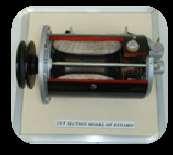
10 Model No. MT-C01 Description CUT-SECTION MODEL OF THREE CYLINDER MPFI ENGINE WITH GEAR BOX MT-C02 CUT-SECTION MODEL OF THREE CYLINDER CARBURATOR ENGINE WITH GEAR BOX MT-C03 CUT-SECTION MODEL OF FOUR CYLINDER MPFI ENGINE WITH GEAR BOX MT-C04 CUT-SECTION MODEL OF FOUR CYLINDER CARBURATOR ENGINE WITH GEAR BOX MT-C05 CUT-SECTION MODEL OF FOUR CYLINDER DIESEL ENGINE WITH GEAR BOX MT-C06 CUT-SECTION MODEL OF FOUR CYLINDER TURBO DIESEL ENGINE WITH GEAR BOX MT-C07 CUT-SECTION MODEL OF FOUR CYLINDER CRDI DIESEL ENGINE WITH GEAR BOX MT-C08 CUT-SECTION MODEL OF SIX CYLINDER DIESEL ENGINE WITH GEAR BOX D Model No.MT-D00 CUT SECTION MODEL OF ENGINE WORKING: The model is made out of full size original, used engine. The Maximum parts and accessories of the engine like cylinder block, Cylinder heads, valve ports, piston, Connecting rod, inlet and Exhaust manifolds, throttle body, Fuel system, Lubrication system, Water pump, radiator, oil pump, Oil pan, air Filter, self-starter, Alternator etc are sectioned to clearly demonstrate the internal constructional details. The reduction gear unit will be coupled to the flywheel of the engine assembly, which is then coupled to the single phase AC motor. So that by running the electric motor the entire function of the engine can be demonstrated. The whole system is mounted on to a sturdy iron frame, and the frame will be provided with caster wheels for easy movement of the entire model. Suitable color imported painting will be carried out along with Miracle coating for the model will be done for extra gloss and shine. The painting will be carried out in such a way that different colors will be use for different components such as Air, oil, petrol, exhaust identification of sectioned area etc according to the colors code for easy identification of different systems and mechanisms. All the hardware s and gears will be suitably electroplated. A switch box with indicator switch will be provided. 10


11 Model No. MT-D01 MT-D02 MT-D03 MT-D04 MT-D05 MT-D06 MT-D07 MT-D08 MT-D09 Description CUT-SECTION MODEL OF SINGLE CYLINDER PETROL ENGINE CUT-SECTION MODEL OF SINGLE CYLINDER DIESEL ENGINE CUT-SECTION MODEL OF THREE CYLINDER MPFI ENGINE CUT-SECTION MODEL OF THREE CYLINDER CARBURATOR ENGINE CUT-SECTION MODEL OF FOUR CYLINDER MPFI ENGINE CUT-SECTION MODEL OF FOUR CYLINDER CARBURATOR ENGINE CUT-SECTION MODEL OF FOUR CYLINDER DIESEL ENGINE CUT-SECTION MODEL OF FOUR CYLINDER CRDI DIESEL ENGINE CUT-SECTION MODEL OF SIX CYLINDER DIESEL ENGINE 11
(WORKING): The model is made out of full size original, used engine, Gear box, clutch etc The Maximum parts and")

12 E Model No.MT-E00\ MODEL OF CUT SECTIONED ENGINE ASSEMBLY WITH CLUTCH AND GEAR BOX (TWO WHEELER )(WORKING): The model is made out of full size original, used engine, Gear box, clutch etc The Maximum parts and accessories of the engine like cylinder block, Cylinder heads, valve/ports, piston, Connecting rod, inlet and Exhaust manifolds, throttle body, Fuel system, Lubrication system, Clutch, Gear box etc are sectioned to clearly demonstrate the internal constructional details. The engine is coupled with Gear Box. The gearbox is coupled to the engine through the clutch and gear selection is done by shifting the gear shift control lever. The whole system is mounted on to a sturdy iron frame, and the frame will be provided with caster wheels for easy movement of the entire model. Suitable color imported painting will be carried out along with Miracle coating for the model will be done for extra gloss and shine. The painting will be carried out in such a way that different colors will be use for different components such as Air, oil, petrol, exhaust identification of sectioned area etc according to the colors code for easy identification of different systems and mechanisms. All the hardware s and gears will be suitably electroplated. A switch box with indicator switch will be provided. Model No. Description MT-E01 CUT-SECTION MODEL OF SINGLE CYLINDER PETROL ENGINE (TWO STROKE) MT-E02 CUT-SECTION MODEL OF SINGLE CYLINDER PETROL ENGINE (FOUR STROKE) 12


13 F Model No.MT-F01 CUT SECTION MODEL OF TWO STROKE SINGLE CYLINDER DIESEL ENGINES. The model is made out of new single cylinder Diesel engine. Maximum parts such as piston, cylinder, cylinder head, inlet and Exhaust manifolds, Fuel Injection pump, oil pump, Fuel Filter, Injector, etc., are sectioned to show the internal constructional details of the engine. The working of individual parts and accessories like Valves, piston, pumps, Crank, Camshaft, etc., can be demonstrated. This model is fixed on a sturdy iron frame. G Model No.MT-G01 CUT SECTION MODEL OF SYNCHROMESH GEAR BOX (WORKING): This is made out of original full size used gearbox, suitably sectioned to show the details of gear mechanism of forward and reverse speeds. A Crank lever is provided to demonstrate the mechanism. Complete unit is mounted on a sturdy iron frame. Model No. MT-G02 CUT SECTION MODEL OF GEAR BOX WITH DIFFERENTIAL (TRANSAXLE) (WORKING): This is made out of original full size used gearbox, suitably sectioned to show the details of gear mechanism of forward and reverse speeds. A Crank lever is provided to demonstrate the mechanism. Complete unit is mounted on a sturdy iron frame. 13
: This mode is made out of original full size used gearbox, suitably sectioned to show the gear")
: This mode is made out of original full size used gearbox, suitably sectioned to show the gear")
: This mode is made out of original full size used gearbox, suitably sectioned to show the gear")
14 Model No.MT-G03 CUT SECTION MODEL OF SLIDING MESH GEAR BOX (WORKING): This mode is made out of original full size used gearbox, suitably sectioned to show the gear mechanism of forward and reverse speeds. A Crank lever is provided to demonstrate the mechanism. Complete unit is mounted on a sturdy iron frame. Model No.MT-G04 CUT SECTION MODEL OF CONSTANT MESH GEAR BOX (WORKING): This mode is made out of original full size used gearbox, suitably sectioned to show the gear mechanism of forward. A Crank lever is provided to demonstrate the mechanism. Complete unit is mounted on a sturdy iron frame. Model No. MT-G05. CUT SECTION MODEL OF FIVE SPEED MANUAL TRANSMISSION (WORKING): This mode is made out of original full size used gearbox, suitably sectioned to show the gear mechanism of forward and reverse speeds. A Crank lever is provided to demonstrate the mechanism. Complete unit is suitably painted and mounted on a sturdy iron frame. 14


15 Model No. MT-G06 CUT SECTION MODEL OF AUTOMATIC TRANSMISSION OF A CAR. The model is made out of full size original used automatic transmission of a car, the transmission will be suitably sectioned to show the internal details, of gear mechanism of forward and reverse speeds. The automatic shifting of the gears can be explained using this model clearly. The model will be mounted on to a tubular frame, Suitable color imported painting will be carried out along with Miracle coating for the model will be done for extra gloss and shine. The painting will be carried out in such a way that different colors will be use for different components such as identification of sectioned area etc according to the colors code for easy identification of different systems and mechanisms. All the hardware s and gears will be suitably electroplated. Model No. MT-G07 CUT SECTION MODEL OF COUNTINOUSLY VARIABLE TRANSMISSION(CVT)- Two Wheeler. The model is made out of full size original used CVT of a two wheeler, the transmission will be suitably sectioned to show the internal details, of gear mechanism. The variation in variator pulley can be explained to demonstrate the speed variation. The model will be mounted on to a tubular frame, Suitable color imported painting will be carried out along with Miracle coating for the model will be done for extra gloss and shine. The painting will be carried out in such a way that different colors will be use for different components such as identification of sectioned area etc according to the colors code for easy identification of different systems and mechanisms. All the hardware s and gears will be suitably electroplated Model No. MT-G08. TRACTOR TRANSMISSION ASSLY WITH GEAR BOX, ROCKSHAFT ASSEMBLY : The model is made out of full size original used Tractor Transmission Assay with Gear Box Rockshaft Assembly Suitable sectioning of the transmission housing is done So as to demonstrate its complete operational principle/details it will be coated with suitable/requested Spl.Duco painting and plating of the Hardware's Etc. will be carried out. And also the model will be provided with suitable mounting option.. 15
: This model is made out of original full size used Transfer Case, suitably sectioned to show the gear mechanism of forward and reverse speeds.")


16 Model No. MT-G09. MODEL OF CUT SECTIONED TRANSFER CASE ASSEMBLY (WORKING): This model is made out of original full size used Transfer Case, suitably sectioned to show the gear mechanism of forward and reverse speeds. A Crank lever is provided to demonstrate the mechanism. Complete unit is mounted on a sturdy iron frame. The model will be finished by suitable colour painting. Model No. MT-G10. DISMANTELING AND ASSEMBLING PRACTICE FOR MANUAL GEAR BOX WITH 360 DEGREE ROTATING STAND. The original car Gear Box will be mounted on to the rolling stand, so that slowly rolling the handle provided the engine can be rotated and lock and any position and angle to enable the students to assemble or dismantle the Gear box, a large oil drip pan is provided at the bottom to collect the small screws, parts and oil dripping. The rotating stand is made out of steel tube with gears for slow speed operation along with self retention wheels. The Paint finished rotating stand is provided with heavy duty caster wheels with brakes. Model No. MT-G11. DISMANTELING AND ASSEMBLING PRACTICE FOR AUTOMATIC GEAR BOX WITH 360 DEGREE ROTATING STAND. The original car Gear Box will be mounted on to the rolling stand, so that slowly rolling the handle provided the engine can be rotated and lock and any position and angle to enable the students to assemble or dismantle the Gear Box, a large oil drip pan is provided at the bottom to collect the small screws, parts and oil dripping. The rotating stand is made out of steel tube with gears for slow speed operation along with self retention wheels. The Paint finished rotating stand is provided with heavy duty caster wheels with brakes. 16
: This")


 CUT SECTION MODEL")


17 H Model No.MT-H00 CUT SECTION MODEL OF STEERING GEAR BOX (WORKING): This model is made out of full size original parts, suitably sectioned and to demonstrate the working of Steering wheel worms, Steering arm, etc., is mounted on a sturdy iron frame. Model No. Description MT-H01 MT-H02 MT-H03 MT-H04 MT-H05 MT-H06 MT-H07 Rack and Pinion type Worm and roller type Recirculating ball type Worm and sector type Two wheeler steering Power steering Hydraulic Power steering Electronic (EPS) CUT SECTION MODEL OF STEERING GEAR BOX (WORKING) WITH WHEEL AND AXLE: This model is made out of full size original parts, suitably sectioned and to demonstrate the working of Steering wheel worms, Steering arm, etc., The Arrangement Of Wheels And Axle Connecting To steering system will be done so the movement of the wheels when rotating the steering wheels can be displayed. 17

18 The model will be mounted on to a tubular frame, Suitable color imported painting will be carried out along with Miracle coating for the model will be done for extra gloss and shine. The painting will be carried out in such a way that different colors will be use for different components such as identification of sectioned area etc according to the colors code for easy identification of different systems and mechanisms. All the hardware s and gears will be suitably electroplated Model No. MT-H08 MT-H09 MT-H10 MT-H11 MT-H12 MT-H13 Rack and Pinion type Worm and roller type Recirculating ball type Worm and sector type Power steering Hydraulic Power steering Electronic (EPS) Description Model NO. MT-H14. TRAINING PLATFORM FOR HYDRAULIC POWER STEERING WORKING. The Working setup of Hydraulic power steering is made out of original hydraulic steering system completely rigged on to a metal frame, where in a complete hydraulic circuitry will be connected with the hydraulic pump motorised to pressurise the hydraulic oil inside the system. The steering system will be with complete suspension system, tyres and wheels. A rotary platform will be provided under the tyres to demonstrate the vehicle load. So that the Steering with and without the hydraulic power can be demonstrated. 18


19 Model NO. MT-H15. TRAINING PLATFORM FOR ELECTRONIC POWER STEERING (EPS) WORKING. The Working setup of Electronic power steering is made out of original Electronic steering system completely rigged on to a metal frame, where in a complete electrical circuitry will be connected with the ECU and 12V power supply. The steering system will be with complete suspension system, tyres and wheels. A rotary platform will be provided under the tyres to demonstrate the vehicle load. So that the Steering with and without the Electrical power can be demonstrated. I Model NO. MT-I01 CUT SECTION MODEL OF SINGLE PLATE COIL SPRING CLUTCH SYSTEM (WORKING): This model is made out of original used parts such as Flywheel, Clutch plates, etc. to demonstrate the working of clutch assembly. By operating the pedal provided the model can be demonstrated. The entire model is mounted on a sturdy iron frame. Model NO. MT- I02 CUT SECTION MODEL OF DIAPHRAM CLUTCH SYSTEM (WORKING): This model is made out of original parts such as Flywheel, Pressure Plate,Clutch plates, etc. to demonstrate the working of clutch assembly. By operating the pedal provided the model can be demonstrated. The entire model is mounted on a sturdy iron frame. 19


20 Model No. MT-I03. CUT SECTION MODEL OF CENTIFUGAL CLUTCH. This model is made out of original used parts, will be suitably sectioned to demonstrate the internal construction details showing the minute information, and working of the same, the model will be suitably painted and mounted on a navopan wooden base. Model No. MT-I04 MODEL OF CUT SECTIONED MULTI PLATE CLUTCH SYSTEM : This model is made out of full size original multi plate clutch which is suitably sectioned to show the multi plate friction plate arrangement and its working principle. The model will be mounted on wooden base, Suitable color imported painting will be carried out along with Miracle coating for the model will be done for extra gloss and shine. The painting will be carried out in such a way that different colors will be use for different components such as identification of sectioned area etc according to the colors code for easy identification of different systems and mechanisms. All the hardware s and gears will be suitably electroplated J Model No.MT-J01 CUT SECTION MODEL OF FULLY FLOATING DIFFEREINTIAL AND REAR WHEEL MECHANISM (WORKING) (HCV): This model is made out of original used heavy vehicle parts, suitably sectioned to show clearly the action of Differential gear box, such as pinion crown wheel in Differential and Brake drums in Rear axle, A Crank handle is provided to demonstrate the model. The model is mounted on a sturdy iron frame. 20
 (LCV): This model is made out of original used light vehicle, suitably")

: This model is made out of original used parts such as Brake drum, Brake Shoes, etc.")
21 Model No.MT-J02 CUT SECTION MODEL OF SEMI FLOATING DIFFERENTIAL AND WHEEL MECHANISM (WORKING) (LCV): This model is made out of original used light vehicle, suitably sectioned to show the action of Differential gear box and Brake drums in Rear axle. A Crank handle is provided to demonstrate the model. The whole model is mounted on a sturdy iron frame. Model No.MT-J03 CUT SECTION MODEL OF LIVE FRONT AXLE ASSEMBLY (WORKING) : This model is made out of original used light vehicle, suitably sectioned to show the action of Differential gear box and Brake drums in Rear axle. A Crank handle is provided to demonstrate the model. The whole model is mounted on a sturdy iron frame. K Model No. MT-K01 CUT SECTION MODEL OF MECHANICAL BRAKE SYSTEM (WORKING): This model is made out of original used parts such as Brake drum, Brake Shoes, etc., suitably sectioned and mounted on a wooden base. By operating the Brake drum and applying the Brake pedal this model can be demonstrated. 21


the entire system will be mounted on a sturdy iron frame. A F.H.")
22 Model No. MT-K02 CUT SECTION MODEL OF AIR BRAKE SYSTEM: The model is made out of Original parts such as Air compressor, Unloader valve, foot valve, Booster, Wheel assembly, air tank, control valve etc Suitably sectioned and mounted on a sturdy iron frame. Model No. MT-K03 MODEL OF AIR BRAKE SYSTEM WORKING: The model is made out of Original parts such as Air compressor, Unloader valve, foot valve, Booster, Wheel assembly, air tank, control valve etc The Brake system will be fitted with two front wheel assembly complete ( with out axle) and the drum will be suitably sectioned to show the working of the brake shoe. Other system will be mounted as it is and will be made to function ( foot brake, hand brake etc will be functional.)the entire system will be mounted on a sturdy iron frame. A F.H.P Single phase220/230 V AC motor will be coupled to the compressor for generation of the air, which is used for the operation of the model. Model No. MT-K04 CUT SECTION MODEL OF DISC BRAKE SYSTEM: (working): The Model is made out of Original parts such as Two Brake disc, two Calliper assembly (one sectioned), two master cylinder (one sectioned) etc, the model is mounted on a sturdy iron frame and can be demonstrated by operating the lever provided. 22
 (WORKING): This model is made out of original parts such as Two Brake drum assembly, one master cylinder (one sectioned), wheel cylinders (one")
 WITH TWO DISC AND TWO DRUM BRAKES: This model contain two disc brakes in the front and two drum brakes at")
23 Model No. MT-K05 CUT SECTION MODEL OF DRUM BRAKE UNIT (HYDRAULIC) (WORKING): This model is made out of original parts such as Two Brake drum assembly, one master cylinder (one sectioned), wheel cylinders (one sectioned), Brake Shoes, etc., the model can be demonstrated by operating the lever provided. Model No. MT-K06 CUT SECTION MODEL OF HYDRAULIC BRAKE UNIT -FOUR WHEEL TYPE (CUT SECTIONED AND WORKING) WITH TWO DISC AND TWO DRUM BRAKES: This model contain two disc brakes in the front and two drum brakes at the rear and it is made out of original parts such as two master cylinder Assembly (one sectioned and one working), wheel cylinder, Brake drum, Brake Shoes, callipers etc., suitably sectioned and mounted on a sturdy iron frame. By operating the lever provided, the working procedure of the model can be demonstrated. Model No. MT-K07 MODEL OF HYDRAULIC BRAKING SYSTEM WITH VACCUM BOOSTER WITH VACUUM PUMP. The model will be made out of Used MARUTI brake aggregates which will be suitably sectioned, Left Front disc and Left rear drum will be made working, using necessary hydraulic connection from the Master cylinder, By operating the brake pedal connected to the Master cylinder through booster, the functioning of disc and drum brake can be demonstrated. The aggregates on the other side will be suitably sectioned to show the internal details and will be kept dummy. All the aggregates will paint finished The entire setup will be mounted on a sturdy iron frame. 23


24 Model No. MT-K08 CUT SECTION MODEL OF DISC BRAKE SYSTEM TWO WHELER. This model is made out of original used parts, will be suitably sectioned And Arranged to demonstrate the internal construction details showing the minute information such as the disc brake assembly, master cylinder on the handle, its piping, front wheel assembly with disc, handle bar with cylinder and brake lever etc., and working of the same can be show by operating the brake lever, the model will be suitably painted and The entire model is mounted on a sturdy iron frame. NOTE: For ABS working model Please Refer Model No. MT-X04 L Model No. MT-L01 CUT SECTION MODEL OF MOCK LAYOUT OF A CAR WIRING (VEHICLE BODY ELECTRICAL SYSTEM) WORKING (BASIC TYPE ): This demonstration board which will give a complete idea of the electrical system of a car. In this demonstration board the actual wiring with parts and accessories of a car had been arranged, according to the electrical circuit of a car and terminals are provided to connect the battery. By giving connection the working of individual parts such as Self starter, Alternator, Wiper Motor, Horn, Head lights, Tail lamps, Parking lamps, Side indicators, Brake light, Distributor, Sparks of spark plugs, etc., can be demonstrated. The parts sectioned to show the internal constructional details. This is a working demonstration model. 24
 WORKING (COMPREHENSIVE TYPE): This demonstration board which will give a complete idea of the electrical")
25 Model No. MT-L02 CUT SECTION MODEL OF MOCK LAYOUT OF A CAR WIRING (VEHICLE BODY ELECTRICAL SYSTEM) WORKING (COMPREHENSIVE TYPE): This demonstration board which will give a complete idea of the electrical system of a car. In this demonstration board the actual wiring with parts and accessories of a car had been arranged, according to the electrical circuit of a car and terminals are provided to connect the battery. By giving connection the working of individual parts such as Self starter, Alternator Motorised and working, Wiper Motor, Water sprayer, Brake fluid indicator, Horn, Head lights with head light adjustment, Fog Lamp, Tail lamps, Parking lamps, Side indicators, Brake light, Distributor, Sparks of spark plugs, power window motor, central locking system, music system, reverse parking assist, etc., can be demonstrated. The parts sectioned to show the internal constructional details. This is a working demonstration model (with inbuilt battery charger and battery ). Model No. MT-L03 CUT SECTION MODEL OF MOCK LAYOUT OF A TRACTOR WIRING (ELECTRICAL SYSTEM OF A TRACTOR) WORKING MODEL (Diesel): This demonstration board which will give a complete idea of the electrical system of a Tractor. In this demonstration board the actual wiring with parts and accessories of a Tractor had been arranged, according to the electrical circuit of a Tractor and terminals are provided to connect the battery. By giving connection the working of individual parts such as Self starter, Alternator, Horn, Head lights, Tail lamps, Parking lamps, Side indicators, Brake light, etc., can be demonstrated. The parts sectioned to show the internal constructional details. This is a working demonstration model (battery not included in the rate). 25
 WORKING MODEL This demonstration board which will give a complete idea of the electrical system of a Two wheeler.")

: This open demonstration working unit is made out of original used parts such as switches, ignition coil,")
26 Model No. MT-L04 MOCK LAYOUT OF A TWO WHEELER WIRING (ELECTRICAL SYSTEM OF A TWO WHEELER) WORKING MODEL This demonstration board which will give a complete idea of the electrical system of a Two wheeler. In this demonstration board the actual wiring with parts and accessories of a two wheeler will be arranged, according to the electrical circuit and terminals are provided to connect the battery. By giving connection the working of individual parts such as Self, Horn, Head lights, Tail lamps, Parking lamps, Side indicators, Brake light, Distributor, Sparks of spark plugs, etc., can be demonstrated. The parts sectioned to show the internal constructional details. This is a working demonstration model. Model No. MT-L05 DEMONSTRATION BOARD OF IGNITION SYSTEM OF AN AUTOMOBILE 4 WHEELER (WORKING): This open demonstration working unit is made out of original used parts such as switches, ignition coil, Distributor, four spark plugs and a battery for power source, with necessary wiring connections. By switching on the switch and by giving rotation to the Distributor, Sequential Sparks in the spark plugs can be demonstrated. Model No. MT-L06 DEMONSTRATION BOARD OF ELECTRONIC IGNITION SYSTEM OF AN AUTOMOBILE 4 WHEELER (WORKING): This open demonstration working unit is made out of original used parts such as switches, Electronic ignition coil, Distributor, four spark plugs and a battery for power source, with necessary wiring connections. By switching on the switch and by giving rotation to the Distributor, Sequential Sparks in the spark plugs can be demonstrated. 26
: This open demonstration-working unit is made out of original used parts such as switch, ignition coil, Magneto Assembly,")
27 Model No. MT-L07 DEMONSTRATION BOARD OF IGNITION SYSTEM OF A TWO WHEELER (WORKING): This open demonstration-working unit is made out of original used parts such as switch, ignition coil, Magneto Assembly, spark plug, with necessary wiring connections. By switching on the switch and by giving rotation to the Magneto Assembly, Sequential Sparks in the spark plug can be demonstrated. Model No. MT-L08 DEMONSTRATION BOARD OF ELECTRONIC IGNITION SYSTEM OF A TWO WHEELER (WORKING): This open demonstration-working unit is made out of original used parts such as switch, Electronic ignition coil, Magneto Assembly, spark plug, with necessary wiring connections. By switching on the switch and by giving rotation to the Magneto Assembly, Sequential Sparks in the spark plug can be demonstrated. Model No. MT-L09 CUT SECTION MODEL OF POWER WINDOWS WITH ONE DOOR. This model is made out of original used parts, will be suitably sectioned And Arranged to demonstrate the internal construction details showing the minute information such as motor and its gear arrangement etc., and working of the same can be show by connecting it to a battery, the model will be suitably painted and The entire model is mounted on a sturdy iron frame. 27
 This model is made out of original used parts, will be suitably sectioned And Arranged to demonstrate the internal construction details showing the minute information such as AC")

28 Model No. MT-L10 CUT SECTION MODEL OF AIR CONDITIONING SYSTEM OF A CAR. (NON WORKING) This model is made out of original used parts, will be suitably sectioned And Arranged to demonstrate the internal construction details showing the minute information such as AC compressor, condenser, radiator, its pipe lining, blower/fan assembly etc., the model will be suitably painted and The entire model is mounted on a sturdy iron frame. Model No.MT-L11 DEMONSTRATION BOARD OF AIR CONDITIONING SYSTEM OF FOUR WHEELER. ( WORKING) This model is made out of original New parts, will be suitably Arranged on to a Metal frame with navopan board to demonstrate details of Piping connection, Wiring circuit with all the accessories such as Cooling Coil, compressor, evaporator, necessary hoses, condenser etc., the model will be made to work using a FHP motor so that by operating the AC panel the operation and cooling effect of the same can be demonstrated, the Model will contain a car Battery for the operation of the blower and Magnetic clutch the entire system will be suitably painted. Model No.MT-L12 DEMONSTRATION BOARD OF MPFI SYSTEM. : This open demonstration Board is made out of original used parts such as such as petrol injector, inlet manifolds, throttle body, distributor, ECU, canister purge valve, carbon canister, fuel tank module, supporting sensors such as lambda sensor, engine speed sensor, cam position sensor etc,., with necessary wiring connections to show the circuit connections. The entire system will be suitably sectioned and mounted on Navopan board. 28


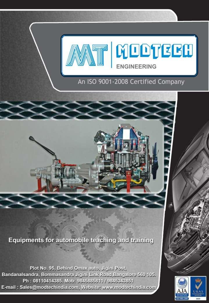
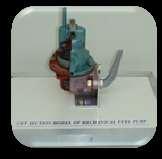
29 Model No. MT-L13 DEMONSTRATION BOARD OF WORKING MODEL MPFI SYSTEM. This open demonstration Board is made out of original used parts such as such as petrol injector, inlet manifolds, throttle body, distributor, ECU, canister purge valve, carbon canister, fuel tank module, supporting sensors such as lambda sensor, engine speed sensor, cam position sensor etc,., with necessary wiring connections to show the circuit connections. The entire system will be suitably sectioned and mounted on Navopan board. By rotating the distributor the spray from the injector and demonstrated along with the spark from the spark plugs. Acrylic fuel tank will be pleased along with the fuel pump module. NOTE: For Circuit printed Demo Board for MPFI and CRDI Refer Model No. MT-X01 and Model No. MT-X02 respectively NOTE: For Charging and starting system Please Refer Model No. MT-X06 and MT-X07 M Model No. MT-M01 DEMONSTRATION BOARD OF FUEL SUPPLY SYSTEM OF A PETROL ENGINE: This demonstration board consists of cut sectioned used parts such as tank, petrol pump, Filter, Carburettor, etc., to show the Fuel supply system. 29


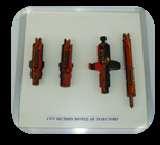
30 Model No. MT-M02 DEMONSTRATION BOARD OF FUEL SUPPLY SYSTEM OF DIESEL ENGINE This demonstration board consists of cut sectioned used parts such as Fuel injection pump, Fuel tank, Filter, Fuel Injector with Automiser, etc., to show the Fuel supply system. Model No. MT-M03 DEMONSTRATION BOARD OF FUEL SUPPLY SYSTEM OF DIESEL ENGINE WORKING: This demonstration board consists of Original parts such as Fuel injection pump, Fuel tank, Filter, Fuel Injector with Atomiser, etc., to show the Fuel supply system. The Fuel injection pump will be motorised and the entire fuel supply circuitry will be connected to show the flow of fuel from tank to filter and to the pump through feed pump and to the injector. When the motor is switched on the FIP rotates creating a pressure inside the injector and according to the timing the diesel spray form the injector can be observed. Model No. Description MT-M03A MT-M03B MT-M03C Four cylinder Inline FIP Four cylinder Rotary FIP Six cylinder Inline FIP 30


31 N Model No. MT-N01. CUT SECTION MODEL OF COMPELETE ONE SIDE MACPHERSON SUSPENSION STRUT WITH DRIVE SHAFT, DISK BRAKE. This model is made out of original used parts, will be suitably sectioned And Arranged to demonstrate the internal construction details showing the minute information With Suspension Strut with spring and shock absorber, disc brake, calliper, wishbone drive shaft etc., and working of the same can be shown, the model will be suitably painted and The entire model is mounted on a sturdy iron frame. Model No. MT-N02. CUT SECTION MODEL OF COMPELETE BOTH SIDE MACPHERSON SUSPENSION STRUT WITH DRIVE SHAFT, DISK BRAKE. This model is made out of original used parts, will be suitably sectioned And Arranged to demonstrate the internal construction details showing the minute information With Suspension Strut with spring and shock absorber, disc brake, callipers, drive shaft etc., and working of the same can be shown, the model will be suitably painted and The entire model is mounted on a sturdy iron frame. Model No. MT-N03. CUT SECTION MODEL OF COMPELETE FRONT SUSPENSION WITH LONGITUDINAL TORSION BAR.. This model is made out of original used parts, will be suitably sectioned And Arranged to demonstrate the internal construction details showing the minute information With Suspension System with longitudinal torsion bar arrangement, shock absorber, etc., and working of the same can be shown, the model will be suitably painted and The entire model is mounted on a sturdy iron frame. 31


32 Model No. MT-N04. CUT SECTION MODEL OF COMPELETE COIL SPRING TYPE FRONT SUSPENSION SYSTEM. This model is made out of original used parts, will be suitably sectioned And Arranged to demonstrate the internal construction details showing the minute information With Suspension with Coil spring and wheels mounted on bearing on tapered spindles of the steering knuckles, drive shaft etc., and working of the same can be shown, the model will be suitably painted and The entire model is mounted on a sturdy iron frame. Model No. MT-N05. CUT SECTION MODEL OF COMPELETE BOTH SIDE WITH DOUBLE WISHBONE SUSPENSION WITH DRIVE SHAFT. This model is made out of original used parts, will be suitably sectioned And Arranged to demonstrate the internal construction details showing the minute information With Suspension Strut with spring and shock absorber, disc brake, callipers drive shaft etc., and working of the same can be shown, the model will be suitably painted and The entire model is mounted on a sturdy iron frame. Model No. MT-N06 CUT SECTION MODEL OF COMPELETE LEAF SPRING SUSPENSION SYSTEM WITH REAR AXLE. This model is made out of original used parts, will be suitably sectioned And Arranged to demonstrate the internal construction details showing the minute information With leaf spring is arranged along with shock absorber etc., and working of the same can be shown, the model will be suitably painted and The entire model is mounted on a sturdy iron frame. 32


33 Model No. MT-N07. CUT SECTION MODEL OF COMPELETE COIL SPRING TYPE REAR SUSPENSION SYSTEM. This model is made out of original used parts, will be suitably sectioned And Arranged to demonstrate the internal construction details showing the minute information With Suspension with Coil spring and axle, wheels mounting, drive shaft etc., and working of the same can be shown, the model will be suitably painted and The entire model is mounted on a sturdy iron frame. Model No. MT-N08. CUT SECTION MODEL OF COMPELETE AIR SUSPENSION SYSTEM. This model is made out of original used parts, will be suitably sectioned And Arranged to demonstrate the internal construction details showing the minute information of Suspension with air bellow, shock absorber, linkages, Air bellow fittings, air valve with connections etc., and working of the same can be shown, the model will be suitably painted and The entire model is mounted on a sturdy iron frame. O Model No. MT-O01 CUT SECTION WORKING MODEL OF LUBRICATING SYSTEM: This model is made out of original used parts, will be suitably sectioned to demonstrate the internal construction details like oil pump, oil filter, oil strainer etc. showing the minute information, and working of the same, the model will be suitably painted and mounted on a navopan wooden base Model No. MT-O02 CUT SECTION WORKING MODEL OF COOLING SYSTEM: This model is made out of original used parts, will be suitably sectioned to demonstrate the internal construction details like radiator, fan blade, water pump and hose showing the minute information, and working of the same, the model will be suitably painted and mounted on a navopan wooden base 33


34 P Model No. MT-P00 Cut Section Model Of Different Automobile Parts And Accessories Suitably Painted And Mounted On A Wooden Board: 34
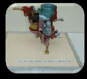
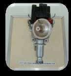
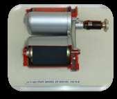
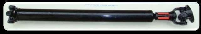
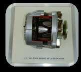
35 Model No. MT-P01 MT-P02 MT-P03 MT-P04 MT-P05 MT-P06 MT-P07 MT-P08 MT-P09 MT-P10 MT-P11 MT-P12 MT-P13 MT-P14 MT-P15 MT-P16 MT-P17 MT-P18 MT-P19 MT-P20 MT-P21 MT-P22 MT-P23 MT-P24 MT-P25 MT-P26 MT-P27 MT-P28 MT-P29 MT-P30 MT-P31 MT-P32 MT-P33 MT-P34 MT-P35 MT-P36 Description Self starter (axle type/non axle type) Dynamo Distributor Mechanical Fuel pump Electrical Fuel pump Carburettors Simple Type-2 wheeler Carburettors Solex Type-4 wheeler Carburettors Mikuni type Radiator Ignition coil Shock absorber Brake cylinder and master cylinder Speedo meter Water pump FIP Pneumatic Governor (Four cyl engine) FIP RQ governor (Six cylinder Engine) FIP RSV governor (Six cylinder Engine) FIP Distributor type ( four Cylinder) I.C.Injector (4 Types) Diesel Filter Gear Lubrication pump Propeller shaft Cone clutch Alternator Silencer Catalytic converter Fuel Pump diaphragm type Oil Pump External Oil Pump internal Vacuum Pump (Vane type) Vacuum Pump (Rotary type) piston Pump (air Compressor) Turbocharger Fluid flywheel/ Torque converter Alkaline Battery Air Cleaner 35
 The Four stroke petrol engine setup will be prepared by using good working condition multi cylinder car engine with")
. All the fittings such as meter, fuel tank, radiator etc.")
36 Q Model No. MT-Q00 FOUR STROKE PETROL CARBURATOR ENGINE SETUP FOR PRACTICE (WORKING CONDITION) The Four stroke petrol engine setup will be prepared by using good working condition multi cylinder car engine with all the fittings of the engine along with radiator, silencer, air filter, starter, battery, alternator, indication meters, fuel tank,electrical wiring with ignition switch etc., all mounted on to a sturdy iron frame with caster wheels (mobile trolley). All the fittings such as meter, fuel tank, radiator etc., along with the engine will be arrange on to the paint finished trolley with its original fittings such as rubber dampers and clamps so as to contain the vibrations. The wiring for the sensors, indication meters etc, will be done so that by cranking the ignition the engine will start working, the indications such as alternator charging, oil pressure, temperature etc., will be displayed on to the necessary indication meter attached. The engine assembly will be serviced,painted with a single colour paint. Model No. Description MT-Q01 Maruti OMNI/800 cc carburettor Engine setup MT-Q02 Maruti Zen/Alto/Esteem(Carburettor) Engine setup MT-Q NE carburettor Engine setup 36
 The Four stroke petrol engine setup will be prepared by using good working condition multi cylinder")
. All the fittings such as meter, fuel tank, radiator etc.")


37 R Model No. MT-R00 FOUR STROKE PETROL MPFI ENGINE SETUP FOR PRACTICE (WORKING CONDITION) The Four stroke petrol engine setup will be prepared by using good working condition multi cylinder car engine with all the fittings of the engine along with radiator, silencer, air filter, starter, battery, alternator, indication meters, fuel tank,electrical wiring with ignition switch etc., all mounted on to a sturdy iron frame with caster wheels (mobile trolley). All the fittings such as meter, fuel tank, radiator etc., along with the engine will be arrange on to the paint finished trolley with its original fittings such as rubber dampers and clamps so as to contain the vibrations. The wiring for the sensors, indication meters etc, will be done so that by cranking the ignition the engine will start working, the indications such as alternator charging, oil pressure, temperature etc., will be displayed on to the necessary indication meter attached. The engine assembly will be serviced,painted with a single colour paint. MPFI engines will be fitted with all necessary sensors, injectors and other MPFI accessories, ECU etc., which will be duly connected by its original wiring harness and will be made to work along with necessary indications. Model No. Description MT-R01 Ambassador Isuzu MPFI Engine setup MT-R02 Maruti 800 CC/Omni MPFI Engine setup MT-R03 Santro MPFI Engine setup MT-R04 Maruti Zen/Alto/Esteem MPFI Engine setup 37
 The Four stroke petrol engine with LPG setup will be prepared by using good working condition multi cylinder car engine")
. All the fittings such as meter, fuel tank, radiator etc.")
38 S Model No. MT-S00 FOUR STROKE PETROL CARBURATOR ENGINE WITH LPG SETUP (WORKING CONDITION) The Four stroke petrol engine with LPG setup will be prepared by using good working condition multi cylinder car engine with all the fittings of the engine along with radiator, silencer, air filter, starter, battery, alternator, indication meters, fuel tank, LPG tank,electrical wiring with ignition switch etc., all mounted on to a sturdy iron frame with caster wheels (mobile trolley). All the fittings such as meter, fuel tank, radiator etc., along with the engine will be arrange on to the paint finished trolley with its original fittings such as rubber dampers and clamps so as to contain the vibrations. The wiring for the sensors, indication meters etc, will be done so that by cranking the ignition the engine will start working, the indications such as alternator charging, oil pressure, temperature etc., will be displayed on to the necessary indication meter attached. The engine assembly will be serviced,painted with a single colour paint. Model No. MT-S01 MT-S02 Description Maruti OMNI/800 cc carburettor Engine with LPG setup Maruti Zen/Alto/Esteem(Carburettor) with LPG Engine setup T Model No. MT-T00 FOUR STROKE PETROL MPFI ENGINE WITH LPG SETUP (WORKING CONDITION) The Four stroke petrol engine with LPG setup will be prepared by using good working condition multi cylinder car engine with all the fittings of the engine along with radiator, silencer, air filter, starter, battery, alternator, indication meters, fuel tank, LPG tank,electrical wiring with ignition switch etc., all mounted on to a sturdy iron frame with caster wheels (mobile trolley). All the fittings such as meter, fuel tank, radiator etc., along with the engine will be arrange on to the paint finished trolley with its original fittings such as rubber dampers and clamps so as to contain the vibrations. The wiring for the sensors, indication meters etc, will be done so that by cranking the ignition the engine will start working, the indications such as alternator charging, oil pressure, temperature etc., will be displayed on to the necessary indication meter attached. The engine assembly will be serviced,painted with a single colour paint. MPFI engines will be fitted with all necessary sensors, injectors and other MPFI accessories, ECU etc., which will be duly connected by its original wiring harness and will be made to work along with necessary indications. 38

 The Four stroke Diesel engine setup will be prepared by using good working condition multi cylinder diesel engine with all the fittings of the engine along")

39 Model No. MT-T01 MT-T02 MT-T03 MT-T04 Description Ambassador Isuzu MPFI Engine with LPG setup Maruti 800 CC/Omni MPFI Engine with LPG setup Santro MPFI Engine with LPG setup Maruti Zen/Alto/Esteem MPFI Engine with LPG setup U Model No. MT-U00. FOUR STROKE DIESEL ENGINE SETUP (WORKING) The Four stroke Diesel engine setup will be prepared by using good working condition multi cylinder diesel engine with all the fittings of the engine along with air filter, starter, battery, alternator, indication meters, fuel tank,electrical wiring etc., all mounted on to a sturdy iron frame with caster wheels (mobile trolley). All the fittings such as meter, fuel tank, radiator etc., along with the engine will be arrange on to the paint finished trolley with its original fittings such as rubber dampers and clamps so as to contain the vibrations. The wiring for the sensors, indication meters etc, will be done and painted with a single colour paint. Model No. MT-U01 MT-U02 MT-U03 MT-U04 MT-U05 MT-U06 MT-U07 MT-U08 MT-U09 Description Tata Car turbo charged Engine assembly Tata Sumo Turbo charged Engine assembly with rotary type Fuel injection Pump Mahindra 540 Engine assembly Ambassador Isuzu Diesel Engine assembly Tata Sumo Non Turbo Engine assembly Tata Safari turbo charged engine assembly Ford 1.4 ZXi engine assembly Hyundai Accent/ScorpioCRDI Engine assembly Single Cylinder Diesel engine setup 39


40 V Model No. MT-V00 TWO WHEELER PETROL ENGINE OF DIFFERENT MAKES IN RUNNING CONDITION The petrol engine setup will be prepared by using good working condition engine with all the fittings of the engine along with silencer, air filter, fuel tank,electrical wiring with ignition switch etc., all mounted on to a sturdy iron frame with caster wheels (mobile trolley). All the fittings such as fuel tank, etc., along with the engine will be arrange on to the paint finished trolley with its original fittings such as rubber dampers and clamps so as to contain the vibrations.. The engine assembly will be serviced,painted with a single colour paint. Model No. MT-V01 MT-V02 MT-V03 MT-V04 MT-V05 MT-V06 Description Bajaj Chetak Engine assembly Suzuki Samurai Engine assembly Yamaha engine assembly TVS super XL (Electronic Ignition Engine) Bajaj Pulsar 150 CC Engine assembly Hero Honda Engine assembly W Model No. MT-W01 TRAINING MODULE FOR THE MPFI PETROL ENGINE. The device is designed based on latest technology petrol engines with Multi point fuel injection system. The trainer helps to simulate engine startup, speedup, slowdown and other actions so as to illustrate the structure and working principle of MPFI engines. Features 1. Real and operating Petrol MPFI engine, illustrating the structure and working process. 2. Coloured circuit diagram on the training Module printed on to 6mm organic glass base.. 40
41 3. Detection terminals for operator to detect various sensors, actuators, electrical signals for engine control unit, such as resistive, voltage, current, frequency and wave form signals are provided on to the printed circuit diagram. 4. Automobile meters are fitted on to the training module along with the printed circuit diagram, to demonstrate engine speed, temperature, fuel pressure, charging light etc., 5. The training module is fitted with diagnostic socket (DLC) for universal automobile decoder(scan tool) to read fault codes, clear fault codes and read data stream. 6. Fault setting switch bank will be provided to induce faults in the training module to demonstrate the fault and to diagnose faults. 7. Good working condition engine will be provided with fuel tank and battery. Throttle control is provided on the module to accelerate. 8. The training module is fabricated using steel pipe frame with spray painted for good looks and the entire setup is provided with caster wheels with brakes for easy movement of the same. Model No. MT-W02 TRAINING MODULE FOR THE CRDI DIESEL ENGINE. The device is designed based on latest technology diesel engines with Common rail direct fuel injection system. The trainer helps to simulate engine startup, speedup, slowdown and other actions so as to illustrate the structure and working principle of CRDI engines. Features 1. Real and operating CRDI Diesel engine, illustrating the structure and working process. 2. Coloured circuit diagram on the training Module printed on to 6mm organic glass base.. 3. Detection terminals for operator to detect various sensors, actuators, electrical signals for engine control unit, such as resistive, voltage, current, frequency and wave form signals are provided on to the printed circuit diagram. 4. Automobile meters are fitted on to the training module along with the printed circuit diagram, to demonstrate engine speed, temperature, fuel pressure, charging light etc., 5. The training module is fitted with diagnostic socket (DLC) for universal automobile decoder(scan tool) to read fault codes, clear fault codes and read data stream. 6. Fault setting switch bank will be provided to induce faults in the training module to demonstrate the fault and to diagnose faults. 7. Good working condition engine will be provided with fuel tank and battery. Throttle control is provided on the module to accelerate. 8. The training module is fabricated using steel pipe frame with spray painted for good looks and the entire setup is provided with caster wheels with brakes for easy movement of the same. 41


42 Model No. MT-W03 DISMANTELING AND ASSEMBLING PRACTICE ENGINE WITH 360 DEGREE ROTATING STAND. The original car engine will be mounted on to the rolling stand, so that slowly rolling the handle provided the engine can be rotated and lock and any position and angle to enable the students to assemble or dismantle the engine, a large oil drip pan is provided at the bottom to collect the small screws, parts and oil dripping. The rotating stand is made out of steel tube with gears for slow speed operation along with self retention wheels. The Paint finished rotating stand is provided with heavy duty caster wheels with brakes. X Model No. MT-X01 INSTRUCTION BOARD FOR ELECTRONIC FUEL INJECTION SYSTEM OF GASOLINE ENGINE. (MPFI) The Instruction board adopts the real components of electronic fuel injection system to illustrate engine fuel system structure and working principle. The components are rigged onto colour circuit diagram. And made functional. Features 1. Real and operatable engine fuel injection system is assembled onto a colour printed board to illustrating the structure and working process. 2. Coloured circuit diagram on the training Module printed on to 6mm organic glass base. Where in the students can compare the diagram and actual diagram. 3. Detection terminals for operator to detect various sensors, actuators, electrical signals for engine control unit, such as resistive, voltage, current, frequency and wave form signals are provided on to the printed circuit diagram. 4. The training module is fitted with diagnostic socket (DLC) for universal automobile decoder (Scan tool) to read fault codes, clear fault codes and read data stream. 5. Fault setting switch bank will be provided to induce faults in the training module to demonstrate the fault and to diagnose faults. 6. Set the line break, grounding short circuit, improper contact or open circuit faults can be induced, user can adjust the number and type of faults. 7. Good working condition Parts will be provided with fuel tank. The instruction board has to be connected to 220V AC socket Which changes to 12V DC internally so that the board works without battery. 8.The training module is fabricated using steel pipe frame with spray painted for good looks and the entire setup is provided with caster wheels with brakes for easy movement of the same. 42
 The Instruction board adopts the real components of electronic fuel injection system( CRDI) to illustrate engine fuel system structure and working principle.")
43 Model No. MT-X02 INSTRUCTION BOARD FOR ELECTRONIC FUEL INJECTION SYSTEM OF DIESEL ENGINE.(CRDI) The Instruction board adopts the real components of electronic fuel injection system( CRDI) to illustrate engine fuel system structure and working principle. The components are rigged onto colour circuit diagram. And made functional. Features 1. Real and operatable engine fuel injection system with partial engine block is assembled onto a colour printed board to illustrating the structure and working process. 2. Coloured circuit diagram on the training Module printed on to 6mm organic glass base. Where in the students can compare the diagram and actual diagram. 3. Detection terminals for operator to detect various sensors, actuators, electrical signals for engine control unit, such as resistive, voltage, current, frequency and wave form signals are provided on to the printed circuit diagram. 4. The training module is fitted with diagnostic socket (DLC) for universal automobile decoder (Scan tool) to read fault codes, clear fault codes and read data stream. 5. Fault setting switch bank will be provided to induce faults in the training module to demonstrate the fault and to diagnose faults. 6. Set the line break, grounding short circuit, improper contact or open circuit faults can be induced, user can adjust the number and type of faults. 7. Good working condition Parts will be provided with fuel tank. The instruction board has to be connected to 220V AC socket Which changes to 12V DC internally, so that the board works without battery. 8. The training module is fabricated using steel pipe frame with spray painted for good looks and the entire setup is provided with caster wheels with brakes for easy movement of the same. Model No. MT-X03 INSTRUCTION BOARD FOR IGNITION SYSTEM. The Instruction board demonstrates two different types of ignition system in one boards with colour circuit diagrams. The structure and operation of the systems can be explained, with the difference of Conventional ignition system and electronic ignition system. 43

44 Features 1 Real and operatable ignition system with partial engine block is assembled onto a colour printed board to illustrating the structure and working process. 2. Coloured circuit diagram on the training Module printed on to 6mm organic glass base. Where in the students can compare the diagram and actual diagram. 3. Detection terminals for operator to detect various sensors, electrical signals for control unit, such as resistive, voltage, current and wave form signals are provided on to the printed circuit diagram. 4. Fault setting switch bank will be provided to induce faults in the training module to demonstrate the fault and to diagnose faults. 5. Set the line break, grounding short circuit, improper contact or open circuit faults can be induced, user can adjust the number and type of faults. 6. Good working condition Parts will be provided with fuel tank. The instruction board has to be connected to 220V AC socket Which changes to 12V DC internally, so that the board works without battery. 7. The training module is fabricated using steel pipe frame with spray painted for good looks and the entire setup is provided with caster wheels with brakes for easy movement of the same. Model No. MT-X04 TRAINING PLATFORM FOR ABS BRAKE SYSTEM. The device is designed on the ABS system, where in the principle of operation and working of the same can be demonstrated. A parts and accessories are arranged on to a Colour printed board. And the system is made functional. Features 1. Real and operatable ABS brake system is assembled onto a colour printed board to illustrating the structure and working process. 2. The front and rear Disc Brake with callipers are coupled to two different three phase motor with electric drives to rotate the front disc and rear disc separately. A brake Pedal along with vacuum booster is connected to the Front calliper system and rear drum brake system, a vacuum pump will be connected to the booster to demonstrate the effect of vacuum in the pedal operation. 3. The Device is connected with Pressure meters to demonstrate the different pressure at different locations in the brake system. 4. Coloured circuit diagram on the training Module printed on to 6mm organic glass base. Where in the students can compare the diagram and actual diagram. 5. Detection terminals for operator to detect various sensors, actuators, electrical signals for engine control unit, such as resistive, voltage, current, frequency and wave form signals are provided on to the printed circuit diagram. 6. The training module is fitted with diagnostic socket (DLC) for universal automobile decoder (Scan tool) to read fault codes, clear fault codes and read data stream. 7. Fault setting switch bank will be provided to induce faults in the training module to demonstrate the fault and to diagnose faults. 44

45 8. Set the line break, grounding short circuit, improper contact or open circuit faults can be induced, user can adjust the number and type of faults. 9. Good working condition Parts will be provided with fuel tank. The instruction board has to be connected to 220V AC socket Which changes to 12V DC internally, so that the board works without battery. 10. The training module is fabricated using steel pipe frame with spray painted for good looks and the entire setup is provided with caster wheels with brakes for easy movement of the same Model No. MT-X05 INSTRUCTION BOARD FOR CENTRAL DOOR LOCKING AND ALARAM SYSTEM. The Instruction board adopts the real components of Central door Locking and alarm system to illustrate Locking and safety system structure and working principle. The components are rigged onto colour circuit diagram. And made functional. Features 1. Real and operatable Central door Locking and alarm system is assembled onto a colour printed board to illustrating the structure and working process. 2. Coloured circuit diagram on the training Module printed on to 6mm organic glass base. Where in the students can compare the diagram and actual diagram. 3. Detection terminals for operator to detect various sensors, actuators, electrical signals for engine control unit, such as resistive, voltage, current, frequency and wave form signals are provided on to the printed circuit diagram. 4. Fault setting switch bank will be provided to induce faults in the training module to demonstrate the fault and to diagnose faults. 5. Set the line break, grounding short circuit, improper contact or open circuit faults can be induced, user can adjust the number and type of faults. 6. Good working condition Parts will be provided with fuel tank. The instruction board has to be connected to 220V AC socket Which changes to 12V DC internally, so that the board works without battery. 7. The training module is fabricated using steel pipe frame with spray painted for good looks and the entire setup is provided with caster wheels with brakes for easy movement of the same. 45


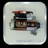
46 Model No. MT-X06 INSTRUCTION BOARD FOR CHARGING SYSTEM. The Instruction board adopts the real components of charging system to illustrate charging system structure and working principle. The components are rigged onto colour circuit diagram. And made functional. Features 1. Real and operatable Charging system such as alternator, meters etc is assembled onto a colour printed board to illustrating the structure and working process. 2. The alternator will be coupled electric motor, and the necessary electrical circuitry will be provided along with warning lamp, ignition switch, voltage meters etc., to demonstrate the working of charging system. 3. And exploded view arrangement of an alternator assembly will be displayed on the board. 4. Coloured circuit diagram on the training Module printed on to 6mm organic glass base. Where in the students can compare the diagram and actual diagram. 5. Detection terminals for operator to detect various sensors, actuators, electrical signals for engine control unit, such as resistive, voltage, current, frequency and wave form signals are provided on to the printed circuit diagram. 6. Fault setting switch bank will be provided to induce faults in the training module to demonstrate the fault and to diagnose faults. 7. Set the line break, grounding short circuit, improper contact or open circuit faults can be induced, user can adjust the number and type of faults. 8. The training module is fabricated using steel pipe frame with spray painted for good looks and the entire setup is provided with caster wheels with brakes for easy movement of the same. Model No. MT-X07 INSTRUCTION BOARD FOR STARTING SYSTEM.. The Instruction board adopts the real components of Starting system to illustrate Starting system structure and working principle. The components are rigged onto colour circuit diagram. And made functional. Features 46

47 1. Real and operatable starting system such as Starter motor, ignition switch etc is assembled onto a colour printed board to illustrating the structure and working process. 2. The Starter will be connected to a battery, and the necessary electrical circuitry will be provided along with ignition switch, voltage meters etc., to demonstrate the working of charging system. 3. And exploded view arrangement of an starter motor will be displayed on the board. 4. Coloured circuit diagram on the training Module printed on to 6mm organic glass base. Where in the students can compare the diagram and actual diagram. 5. Detection terminals for operator to detect various sensors, actuators, electrical signals for engine control unit, such as resistive, voltage, current, frequency and wave form signals are provided on to the printed circuit diagram. 6. Fault setting switch bank will be provided to induce faults in the training module to demonstrate the fault and to diagnose faults. 7. Set the line break, grounding short circuit, improper contact or open circuit faults can be induced, user can adjust the number and type of faults. 8. The training module is fabricated using steel pipe frame with spray painted for good looks and the entire setup is provided with caster wheels with brakes for easy movement of the same. Model No. MT-X08 INSTRUCTION BOARD FOR REVERSE CAMERA AND PARKING ASSIST SYSTEM. The Instruction board adopts the real components of Reverse camera and Parking Assist system to illustrate Reverse camera and Parking Assist system structure and working principle. The components are rigged onto colour circuit diagram and made functional. Features 1. Real and operatable Reverse camera and Parking Assist system is assembled onto a colour printed board to illustrating the structure and working process. 2. Coloured circuit diagram on the training Module printed on to 6mm organic glass base. Where in the students can compare the diagram and actual diagram. 3. Detection terminals for operator to detect various sensors, actuators, electrical signals for engine control unit, such as resistive, voltage, current, frequency and wave form signals are provided on to the printed circuit diagram. 4. Fault setting switch bank will be provided to induce faults in the training module to demonstrate the fault and to diagnose faults. 5. Set the line break, grounding short circuit, improper contact or open circuit faults can be induced, user can adjust the number and type of faults. 6. Good working condition Parts will be provided with fuel tank. The instruction board has to be connected to 220V AC socket Which changes to 12V DC internally, so that the board works without battery. 7.The training module is fabricated using steel pipe frame with spray painted for good looks and the entire setup is provided with caster wheels with brakes for easy movement of the same. 47


48 Model No. MT-X09 INSTRUCTION BOARD FOR AIR BAG SYSTEM. The Instruction board adopts the real components of Air bag system to illustrate Air bag safety system structure and working principle. The components are rigged onto colour circuit diagram and made functional. Features 1.Real and operatable Air bag system is assembled onto a colour printed board to illustrating the structure and working process 2. The Vehicle Crash is Simulated by pushing and hitting the crash sensor along the rail provided to demonstrate the quick air bag inflation. 3. Coloured circuit diagram on the training Module printed on to 6mm organic glass base. Where in the students can compare the diagram and actual diagram. 4. Detection terminals for operator to detect various sensors, actuators, electrical signals for engine control unit, such as resistive, voltage, current, frequency and wave form signals are provided on to the printed circuit diagram. 5. Fault setting switch bank will be provided to induce faults in the training module to demonstrate the fault and to diagnose faults. 6. Set the line break, grounding short circuit, improper contact or open circuit faults can be induced, user can adjust the number and type of faults. 7. Good working condition Parts will be provided with fuel tank. The instruction board has to be connected to 220V AC socket Which changes to 12V DC internally, so that the board works without battery. 8. The training module is fabricated using steel pipe frame with spray painted for good looks and the entire setup is provided with caster wheels with brakes for easy movement of the same. Y Model No. MT-Y01 SINGLE CYLINDER FOUR STROKE DIESEL ENGINE TEST RIG Engine: New AV1 Kirloskar Engine, 5HP,1500 RPM 4 Stroke Water cooled Parameters measured 1. Performance test 2.Heat balance test 48
 Digital")
49 COMPUTERIZED MODULE Parameters measured for Computerization module 1. Indicated HP 2. Indicated Torque 3.Combustion Pressure Vs Volume 4.Combustion Pressure Vs Crank angle 5.IMEP 6.Heat release curve Standard Accessories Fuel Measurement consumption by Volumetric method Air Consumption using standard orifice & MS Air box Digital RPM meter (Except Mechanical loading) Digital Electronic torque controller for Eddy current dynamometer Digital temperature gauges (Air IN, Exhaust OUT, Cooling Water IN, Cooling Water OUT) Water flow Measurement through Rotor meter 2400 LPH Model No. MT-Y01-A MT-Y01-B MT-Y01-C MT-Y01-D Description With Rope Brake Dynamometer With Hydraulic Brake Dynamometer With Electrical Dynamometer With Eddy Current Dynamometer Model No. MT-Y02 FOUR STROKE FOUR CYLINDER PETROL ENGINE TEST RIG. Engine: Re-conditioned/Brand New MPFI Engine (De-rated 10HP, 1500rpm) Parameters measured 1. Performance test 2. Heat balance test 3.Morse test Standard Accessories Fuel Measurement consumption by Volumetric method Air Consumption using standard orifice & MS Air box Digital RPM meter (Except Mechanical loading) Digital Electronic torque controller for Eddy current dynamometer Digital temperature gauges (Air IN, Exhaust OUT, Cooling Water IN, Cooling Water OUT) Water flow Measurement through Rotormeter 2400 LPH 49
50 Model No. MT-Y02-A MT-Y02-B MT-Y02-C MT-Y02-D MT-Y02-E Description With Rope Brake Dynamometer With Hydraulic Brake Dynamometer With Electrical Dynamometer With Eddy Current Dynamometer With Eddy Current Dynamometer & Computerized Module Model No. MT-Y03 TWO CYLLINDER FOUR STROKE DIESEL ENGINE TEST RIG Engine: New TV2 Kirloskar Engine, 14HP, 1800 RPM 4 Stroke Water cooled Parameters measured 1. Performance test 2. Heat balance test Standard Accessories Fuel Measurement consumption by Volumetric method Air Consumption using standard orifice & MS Air box Digital RPM meter (Except Mechanical loading) Digital Electronic torque controller for Eddy current dynamometer Digital temperature gauges (Air IN, Exhaust OUT, Cooling Water IN, Cooling Water OUT) Water flow Measurement through Rotor meter 2400 LPH Model No. MT-Y03-A MT-Y03-B MT-Y03-C MT-Y03-D MT-Y03-E Description With Rope Brake Dynamometer With Hydraulic Brake Dynamometer With Electrical Dynamometer With Eddy Current Dynamometer With Eddy Current Dynamometer & Computerized Module 50
51 Model No. MT-Y04 FOUR STROKE SINGLE CYLINDER VCR ENGINE TEST RIG. Engine: New AV1 Kirloskar Variable Compression Ratio (VCR) Engine, 5HP,1500 RPM 4 Stroke Water cooled Parameters measured 1. Performance test 2. Heat balance test Standard Accessories Fuel Measurement consumption by Volumetric method Air Consumption using standard orifice & MS Air box Digital RPM meter (Except Mechanical loading) Digital Electronic torque controller for Eddy current dynamometer Digital temperature gauges (Air IN, Exhaust OUT, Cooling Water IN, Cooling Water OUT) Water flow Measurement through Rotor meter 2400 LPH Model No. MT-Y04-A MT-Y04-B MT-Y04-C MT-Y04-D MT-Y04-E Description With Rope Brake Dynamometer With Hydraulic Brake Dynamometer With Electrical Dynamometer With Eddy Current Dynamometer With Eddy Current Dynamometer & Computerized Module Model No. MT-Y05 FOUR WHEELER CHASSIS DYNAMOMETER Characteristics Tests can be done by only one person on the car (without having to operate in the computer) Standard connection RS232 to any computer with no need of installing a special card. Easy and powerful Software and High speed data collection General data Maximum power 240 Hp Terminal speed Km/h Details about roller Diameter 400 mm Wheel base Max: 2800mm and Track Width Max: 2100 mm 51
52 Specifications Power supply: 220V 50Hz/60Hz Data transfer: RS232C Roller rpm input connector Type of sensor: Digital Pick-Up (Non Contact Type) Type of input: logical Level (active at high level) Maximum frequency: 15 KHz (6,000 rpm with 150 teeth) Maximum cable length: 6m Run/Stop input SWITCH Engine rpm input: capacitive type (reads high voltage pulses on ignition cables) Parameters Measured 1. Horse Power at Wheel 2. Torque 3. Exhaust gas temperature Model No. MT-Y06 TWO WHEELER CHASSIS DYNAMOMETER Characteristics Tests can be done by only one person over the bike (without having to operate in the computer). Standard connection RS232 to any computer with no need of installing a special card. Easy and powerful Software. Adjustable wheelbase between 850 mm and 1600 mm General data Maximum power 50 Hp Terminal speed 235 Km/h Details about roller Diameter 230 mm Roller weight of 136 kg. Inertia 1 kg.m2 Specifications Power supply: 220V 50Hz/60Hz Data transfer: RS232C Roller rpm input connector Type of sensor: Digital Pick-Up Type of input: logical Level (active at high level) Maximum frequency: 15 KHz (6,000 rpm with 150 teeth) Maximum cable length: 6m Run/Stop input SWITCH Engine rpm input: capacitive type (reads high voltage pulses on ignition cables) Display: LCD 16x2 Characters. Two control buttons in the panel. Model No. MT-Y07 SHOCK ABSORBER TEST RIG The Shock Absorber tester is used to find the performance of the damper under various load condition. The Rig is useful to compare the different types of shock absorber available in the market. Using this rig we can find the time taken by the shock absorber to compress and rebound. A load cell is provided at the bottom of the shock absorber to know the load transverse during the gradual shock. 52

 3.")

53 Z TOOLS AND EQUIPMENTS Model No. MT-Z01 BLUE TOOTH WHEEL ALIGNER (CABLELESS & CORDLESS) 1. 4 Measuring heads with 6 CCD sensors 2. Measures Camber, Caster, Toe, Set Back, Thrust angle, KPI 3. Spoiler Program 4. Data Bank about 60,000 vehicles 5. DELL Computer System with 17" TFT monitor, Data Manager Software 6. 4 x Wheel Clamp 12" - 20"; 7. 2 x Turn Table Model No. MT-Z02 COMPUTERISED WHEEL BALANCER Computerised Wheel Balancer 1. Maximum Rim Dia : 10" - 26" 2. Maximum Wheel Dia : 900 mm (35") 3. Maximum Wheel Weight : 65Kg 4. Readout accuracy : 1g 5. Motorised Model No. MT-Z03 VIDEOGRAHIC WHEEL BALANCER Videographic Wheel balancer 1. Maximum Rim Dia : 10" - 24" 2. Maximum Wheel Weight : 65Kg 3. Readout accuracy : 1g 4. Motorised, Optional Electric Brake 1. Cycle time : < 15 seconds 53
 Internal Locking Rim Dimensions: 355mm-585mm (14-23 ) Max Tyre Diameter: 950mm (37 ) Max Tyre Width: 410mm (16 ) Bead Breaker")

54 Model No. MT-Z04 TYRE CHANGER External Locking Rim Dimensions: 300mm-510mm (12-20 ) Internal Locking Rim Dimensions: 355mm-585mm (14-23 ) Max Tyre Diameter: 950mm (37 ) Max Tyre Width: 410mm (16 ) Bead Breaker Force (10bar) : 2500Kg Working Pressure: 8-10bar( Psi) Power Supply Voltage: 220V (Single Phase) Model No. MT-Z05 AUTOMATIC TYRE INFLATOR Power Supply 1PH, 110V - 230V, 50Hz Power- 40W Working Temp -20 degree ~70 degree Max. Compressed Air Pressure input pressure: psi Max. over pressure : 250 psi Output Air Pressure 4.5Kg/cm2, 65psi Measuring Range 5 ~ 150 psi/0.3 ~ 8bar/0.3 ~ 8Mpa Accuracy ±0.5psi/0.03bar/0.3Mpa of full scale Dimension 620*350*180(mm) Net Weight 6.2Kg Display 4 Digit LCD 1.2 height display Model No. MT-Z06 NITROGEN GENERATOR Power Supply: 220 V AC Maximum Input pressure: 145 PSI Maximum Output pressure: 75PSI Purity of Nitrogen: 95% Nitrogen Producing Speed: 160 Litres/min 54


55 Model No. MT-Z07 LOW RAISE LIFT Lifting capacity: 3000Kg Max Lifting Height: 1000mm Min Height: 120mm Space Between Platforms: 700mm Platform Length: 1400mm-1900mm; Width 1760mm Single Platform Width: 530mm Power Supply Voltage:380V 3ph Model No. MT-Z08 TWO POST LIFT 1. Capacity : 3200 Kg 2. With Base floor plate 3. Three Stage short arms suitable for off road vehicles 4. Min. floor height 140 mm & Max. lifting height 2056 mm 5. Chain drive Model No. MT-Z09 FOUR POST LIFT Four Post Lift with flat runways 1. Capacity : 3500 Kg 2. Motor Capacity : 2.6 KW 55

 1. Measures CO,HC,CO2,O2 2. Engine RPM for Sealed engines 3. Oil Temperature measurement 4.")

56 Model No. MT-Z10 TWO POST LIFT 1. Capacity : 3.5 Tons 2. Electro Hydraulic Symmetrical Supporting Column 3. Passage Width : 2486 mm 4. Lifting Height: 1950 mm 5. Power Supply :Three Phase or Option of Single phase also Model No. MT-Z11 FOUR POST LIST SUITABLE FOR WHEEL ALIGNMENT WITH BUILT IN WHEELS FREE LIFT 1. Capacity : 3500 Kg 2. Motor Capacity : 2.6 KW Model No. MT-Z12 GAS ANALYSER (BLACK BOX VERSION) 1. Measures CO,HC,CO2,O2 2. Engine RPM for Sealed engines 3. Oil Temperature measurement 4. Air Fuel Ratio and Lambda Measurements 5. Option to add Nox measurement facility 6. OMIL Class1 category 7. RS 232 Port Model No. MT-Z13 SMOKEMETER 1. Peak and Average Smoke density measurements 2. Measures in KM-1,HSU,FSN and mg/m³ 3. Free or Steady state operation use 4. Rapid Warmup time and self zeroing facility 5. Integral DOT Matrix printer as standard supply 6. Optional Trolley 56


57 Model No. MT-Z14 MULTISCAN FOR PETROL / DIESEL VEHICLES 1. Complete Worldwide Coverage 2. Upgradation through Internet 3. Big Capacity 128MB with software's for Japanese, Korean, Indian Vehicles 4. DTC, Live Reading, Actuation tests and Keycoding 5. Connector locations, Wiring Diagrams and help menus 6. Real-time PC interface through USB port Model No. MT-Z15 PAINTBOOTH 1. Positive Pressure Paint Booth 2. Size :L x W x H = 6800 x 3800 x 2400 mm 3. Double walled with Insulation 4. With Metal Base with three stage filtration unit 5. Diesel fired Burner, 1,00,000 K cal / hr HP, m³/hr 1440 rpm Air Inlet Blower Model No. MT-Z16 AC SERVICE STATION 1. Functions: Vacuum,Recharging,Refrigerant purifying and recycling 2. Discharge used Oil and Refill new Oil 3. High Pressure and Low pressure Alarm 4. Empty tank alarm 57


58 Model No. MT-Z17 BATTERY CHARGER Patented Sulphating Recovery Program Short Circuit shutdown without blown fuse Reverse Polarity Protection 3-stage charging: CI-CV-Float Model No. MT-Z18 BATTERY TESTER WITHOUT PRINTER 50 CCA to 2000 CCA battery size Display shows capacity in % available CCA and battery condition Tests discharged batteries and Battery recharge indicator Starter test 12/24/36 volt systems and Alternator Ripple Test Model No. MT-Z19 VACUUM BRAKE / CLUTCH BLEEDER Pneumatic Brake Bleeder with an extractor and refiller set One Man Operation with safety cut off Uses Vacuum to draw the Old brake fluid from the Calliper Useful for Clutch bleeding also Model No. MT-Z20 BRAKE FLUID TESTER Simple and Effective tool shows the Condition of the Brake fluid with automatic shut off when not in use 58


 chuck")
59 Model No. MT-Z21 GLOW PLUG TESTER Test the Glow Plug / Heater Plug Test the glow plug without removing from the Engine Model No. MT-Z22 CYLINDER LEAKAGE TESTER Checks the Leakage in the Cylinder Head By injecting a measured amount by air into each cylinder and rate of leakage Model No. MT-Z23 CLICK ADJUSTER - TAPPET ADJUSTER Click adjuster Micro meter Tappet adjuster Suitable for all types of Push rod Engines All OHC engines with top adjustment Inlet and Exhaust valves No need for feeler gauge Model No. MT-Z24 EEZI-LAP Eez lap oscillating Valve lapper Fits with all power drill with normal 5/16" ( 8 mm ) chuck Converts the rotary drill to oscillating action / grinding motion 59


60 Model No. MT-Z25 COMMON RAIL FLOW METER Measures the return flow in the injectors Supplied with adaptors suitable Bosch, Delphi, Denso and Siemens Injectors Model No. MT-Z26 CAR CRASH EQUIPMENT CHASSISLINER - LIFT N RAK Kg Scissor lift 2. Tilt N Turn Tower for pulling upto 8 Tons 3. Includes 4 Nos adjustable Unibody tie down clamps 4. 9 feet Bed length, 38" Bed Width and 37" Lifting Height 5. With Ramp for lower profile vehicles 6. Suitable for Passenger cars 7. Supplied with the Tools for pulling Model No. MT-Z27 MIG WELDING Input voltage : 3 Phase 400V Welding current range: Amps Weldable wires: Steel wire: mm Stainless Steel Wire: mm Aluminium Mg-Si Wire: mm Model No. MT-Z28 PLASMA CUTTER Input Voltage 220 V Cutting Current 5-40 Amps Max. Thickness of the sheet for cutting 12 mm Air Pressure required Bar 60


61 Model No. MT-Z29 SPOT WELDING Synergetic Adjustment Automatically sets the setting according the selected tool & sheet thickness Continuous Single spot and Pulsed single spot Adjustable Time and Spot Welding Current STORE button to save the Customer settings Compressed air pressure to low mechanical strength Overload protection Pneumatic Gun supplied as a standard accessory Model No. MT-Z30 HOT WATER CLEANER New professional handgrip with EPT system and SWIVEL joint to prevent hose twisting. 10 m H.P. hose with screw coupling, 70 cm stainless steel lance, H.P. nozzle. Remote control... total stop TSR Pressure - bar Volume - l/h Outlet water temperature - C Oil consumption - kg/h... 5,8 Voltage - Ph-V-Hz... 3 ~ 400V ~ 50Hz Absorbed power - KW... 5,5 RPM Dimensions - LxPxH x 70 x 88 Weight - Kg Model No. MT-Z31 SPARK PLUG CLEANER AND TESTER Spark Plug Cleaner works on the Pneumatic air supply with the requirement of Air Pressure 8-10 kg/cm². It performs abrasive sand blast cleaning first and then air cleaning. The cleaned spark plug is then fitted in the hole and the HT cable is connected. The performance of the spark can be viewed in the inspection hole Suitable for M10, M14 and M18 Plugs and supplied with ½ Kg of abrasive sand material Specification Power Supply: 220V AC, 50 Hz Pneumatic Supply required: 8 10 Kg/cm² Accessories Adaptor : 3 Nos. (suitable for M10,M14,M18) Abrasive Sand: 500 gms. 61
 Motors 3.7 KW for main drives & 0.")
62 Model No. MT-Z32 INJECTOR CLEANER & TESTER 1. Suitable for cleaning 4 Injectors simultaneously 2. Ultra Sonic Bath tub as standard supply 3. Uniformity test, Spray test, Leakage test and Auto test Model No. MT-Z33 FUEL INJECTION PUMP TEST BENCH Drive Belt No. of Cylinders 6 (Six) Motors 3.7 KW for main drives & 0.7 KW for Fuel supply Tachometer Digital Electronic RPM with electronic Timer Strokes Electronic automatic shots per minute Speed Range RPM Phasing High Pressure Phasing (standard) Pr. Gauges Two (for fuel supply & high pressure phasing) Speed control Fully controllable from both sides Color Oasis Green Capability Inline & Rotary Pumps testing Model No. MT-Z34 ARBOR PRESS HAND OPERATED TWO TON CAPACITY MAXIMUM PRESSURE Exerted (tons kgs) : 2 tons 2000 Centre to bake (inch mm) : 7.1 / Maximum height from base to guide (inch mm) : Maximum height arbor plate to guide (inch mm) : 13.1/2 345 Size of arbor round or square (inch mm): 1.3/4 45. ; Approx net weight kgs : 85. Model No. MT-Z35 High Rate Discharge Tester As the name suggests, this tester works by rapidly discharging a battery. This is a very dangerous test to carry out, and it is very hard on the battery. If you can avoid carrying out this type of test and can carry out a no-load test instead, you should do so. With the high rate discharge test, the length of time the battery can maintain a sufficiently high voltage decides if the battery is serviceable or not. When you are confronted with a machine that is having starting problems, there are a number of possible reasons: Faulty or failing battery. Loose or dirty wiring connections. Faulty starter motor. Faulty alternator. (Alternator testing procedure). Loose or worn alternator drive belt. Machine operator not using the correct starting technique. Faulty cold-start system. 62


63 Model No. MT-Z36 CAR WASHER Single Plunger car washer model RSP-3 with 3 HP Motor and 12 mtrs hose and two guns 1. Number of Guns: 2 60, Working Pressure: 25 kgs 3. Discharge per Gun: 24 LPM 4. Length of Hose: 12 mtrs 5. Motor HP: 3 HP, 3 phase power supply Model No. MT-Z37 BRAKE LINING REVETING MACHINE-FOOT OPERATED Foot Operated Brake shoe riveting machine for brake shoes and for clutch discs for cars, vans. It is perfect for rivet brake shoes and clutch discs of any kind of vehicles since there is enough space between the tool and die punch. The riveting machine has a new innovative die-punch base that creates a perfect holding and grip, with which possible deviations or imbalances in the riveting process and the brake shoe coverings are avoided Technical Specification Maximum distance from the die holder to the back die 40 mm. Min. distance from the die holder to the back die 0 mm. Max. stroke 30 mm. Punches bases kit for riveting tubular and semi-tubular rivets of warm material: 4, 5, 6, 8,10 mm. Model No. MT-Z38 STARTER / ALTERNATOR TEST BENCH Specification 1.Motor 2 hp three phase 1500rpm 2. Digital dc voltmeter of 3.5 digit display with minimum readable upto 0.1 volt of meco make 3. Digital dc ammeter for load of 3.5 digit display with minimum readable upto 1 amp of meco make. 4. Digital make rpm indicator rpm of selection make 5. Speed sensor for sensing starter speed 6. Alternator loading through wire wound resistors of 0-50 amps capacity 5. Alternator loading through 4nos rotary switches. 6. Two directional rugged mounting arrangement to suit your various range of alternators. 7 Provision for two speed check with two set of pulley and belts 8 Starter free spin testing upto 100amps capacity v series lamp test facility also available. 63
64 Model No. MT-Z39 VALVE REFACER Smooth working with 100% efficiency. Slides have set in springs to maximum rigidity. Provides grinding from 0º to 90º, Precision built, under stringent quality control measures. Produces mirror proof finish without chatter marks. Easy to handle, eliminates time-consuming operations of lapping etc. Common drive with one motor for grinding wheel, valve spindle and coolant pump, Centrifugal pump provides constant water supply for better finish. Well protected against in- grease, dirt, dust, and coolant. 1. Valve stem capacity : 6 mm to 14 mm, 2. Valve angle adjustment range : 0º to 90º, 3. Valve head capacity : Up to 90mm, 4. Grinding wheel size : 5" 1/2 5/8, 5. Butt grinding wheel : 4 3/4 5/8, 6. Grinding wheel spindle : 4000RPM, 7. Work head spindle : 175RPM, 8. Power required : 0.5 H.P. 200/220 Volts. A.C, 9. Net weight : 100kg (+25 kg. for packing), Spare Parts: 1. Collets1/4 to 9/16 : 2 nos., 2. Diamond Dresser : One no, 3. C-Spanner : 1 eac Model No. MT-Z40 OTHER EQUIPMENTS Model No. MT-Z40-A MT-Z40-B MT-Z40-C MT-Z40-D MT-Z40-E MT-Z40-F MT-Z40-G MT-Z40-H MT-Z40-I MT-Z40-J MT-Z40-K MT-Z40-L MT-Z40-M MT-Z40-N MT-Z40-O MT-Z40-P MT-Z40-Q MT-Z40-R MT-Z40-S MT-Z40-T MT-Z40-U MT-Z40-V MT-Z40-W MT-Z40-X MT-Z40Y MT-Z40-Z Description Petrol Compression Tester Mechanical Wheel Alignment Diesel Injector Cleaning Machine Hydraulic Bearing Puller Diesel Compression Tester Air Compressor Pressure Gauge Carburettor repair tool kit. Distributor tester Pneumatic Gun Tool valve grinding suction type (Consumable tool) Cylinder gauge, bore dial gauge with standard accessories (50-150mm) Compression gauge to read 120kg/sq cm and vacuum gauge 0-75cm (Petrol) Filling jig for adjusting the piston ring gap Tachometer (Counting type) Connecting rod alignment fixture Puller set universal for bearing and bushes Piston ring compressor Valve key inserter High rate discharge tester AVO Meter (Digital multi meter) Piston groove cleaner Multimeter Timing light RPM meter Hydraulic Press 5 Ton Capacity Floor Crane 1.5 Ton Capacity 64
65 Note: we can also supply any other model as per your requirement Thanking you, Yours faithfully, For MODTECH S/D Partner 65
66 66
AUTOMOBILE ENGINEERING LAB
 AUTOMOBILE ENGINEERING LAB LAB & EQUIPMENTS NAME C O N T E N T S AUTO MOBILE ENGINEERING LAB Cut Section Four Stroke Single Cylinder Cut Section Two Stroke Single Cylinder Cut Section Model of Steering
Department of Mechanical Engineering UBMC701 AUTOMOBILE ENGINEERING QUESTION BANK VEHICLE STRUCTURE AND ENGINES. Part A (Two Marks Questions)
") Department of Mechanical Engineering UBMC701 AUTOMOBILE ENGINEERING QUESTION BANK UNIT- I VEHICLE STRUCTURE AND ENGINES 1. Define Automobile. Give the typical specifications of an automobile 2. Name the
Department of Mechanical Engineering UBMC701 AUTOMOBILE ENGINEERING QUESTION BANK UNIT- I VEHICLE STRUCTURE AND ENGINES 1. Define Automobile. Give the typical specifications of an automobile 2. Name the
INDIRA TECHNICAL EDUCATION SOCIETY, NASHIK
 INDIRA TECHNICAL EDUCATION SOCIETY, NASHIK CER T IF IC AT E CO URS E AUTOMOBILE TECHNICIAN ( ATT ) PAPER - I EXAM SCHEME: THEORY PAPER I - 100 MARKS 3 HRS. THEORY PAPER II - 100 MARKS 3 HRS. PRACTICAL
Vehicle and Engine Technology
 Vehicle and Engine Technology Second Edition List of Chapters: Preface to the first edition Preface to the second edition 1 Vehicle body and chassis layout 1.1 The motor car 1.2 Commercial vehicles 1.3
Motorcycle parts compatibility on ebay.co.uk
 Motorcycle parts compatibility on ebay.co.uk Review the full list of categories and subcategories in which you can list motorcycle and scooter parts. Last updated: 10 August 2016 Motorcycle Parts (10063)
AUTO MECHANICS. PAPER 1: will consist of forty multiple-choice objective questions all of which are to be answered in 1 hour for 40 marks.
 SCHEME OF EXAMINATION AUTO MECHANICS There will be three papers, Papers1, 2 and 3 all of which must be taken. Papers 1 and 2 shall be a composite paper to be taken at one sitting. PAPER 1: will consist
ADVANCED TRAINING INSTITUTE, HYDERABAD
 Revision: 00 LEARNING CONTENT Page 1 of 9 III COURSE CODE AUTO-01 COURSE TITLE AUTOTRONICS (Diagnosis of Sensors and Actuators by using Scan Tool) On completion of the course, the learner will be able
Drawing Page Drawing Page
 Contents Drawing Page Drawing Page L4 Engine...1 L4 Engine - Exploded View...2 V6 Engine...3 V6 Engine - Exploded View... 4 Oil Filter...5 VTEC (Variable Timing Electronic Control) System... 6 Fuel and
MANUAL OPERATION N98-ND4500. Operates Electrically. WEIGHT & DIMENSIONS 140cm x 80cm x 130cm (LxWxH) Net Weight: 180 kg Gross Weight: 250 kg
 Net Weight: 180 kg Gross Weight: 250 kg") TABLE OF CONTENTS HYBRID TECHNOLOGY Hybrid Cut-Away Engine, Prius Manual Operation 1 Hybrid Cut-Away Engine, Prius Electrical Operation 1 Hybrid Cut-Away Trainer, Prius Electrical Operation 1 Biodiesel
TABLE OF CONTENTS HYBRID TECHNOLOGY Hybrid Cut-Away Engine, Prius Manual Operation 1 Hybrid Cut-Away Engine, Prius Electrical Operation 1 Hybrid Cut-Away Trainer, Prius Electrical Operation 1 Biodiesel
PRICE LIST ITEM PRICE $ CORE
 A/C Clutch $20.00 A/C Compressor $35.00 $10.00 A/C Condenser $25.00 $5.00 A/C Evaporator $15.00 A/C Hose(S) $15.00 Accelerator Cable $10.00 Air Bag $30.00 Air Bag Sensor $10.00 Air Cleaner $15.00 Air Filter
L_All_Vocational_Ed_Auto. Sector: Automobile. S.No Specialization Page No. 1 Automobile 2-15
 L_All_Vocational_Ed_Auto Sector: Automobile S.No Specialization Page No. 1 Automobile 2-15 1 NATIONAL VOCATIONAL EDUCATION QUALIFICATION FRAMEWORK SECTOR: AUTOMOBILE SPECIALIZATION: AUTOMOBILE S.No. Certificate
Home About Us Products Certificate Contact Us
 Home About Us Products Certificate Contact Us http://www.bksmotors.in/products/skoda/skoda octavia wagon spare parts/ 1/10 Skoda Octavia (Wagon) Spare Parts Home Products Skoda Skoda Octavia (Wagon) Spare
Warranty Information. Summary of parts covered. The warranty experts
 Warranty Information Summary of parts covered The warranty experts 2 Star Cover This cover applies to vehicles over 1,000. valves and decokes), cylinder head (excluding cracks and overheating damage),
WE JUST MADE YOUR DRIVE A LITTLE MORE RELAXING. THE ENHANCED COVERAGE FOR YOUR BMW CPO VEHICLE.
 WE JUST MADE YOUR DRIVE A LITTLE MORE RELAXING. Introducing THE CERTIFIED PRE-OWNED (CPO) WRAP, THE ENHANCED COVERAGE FOR YOUR BMW CPO VEHICLE. When you purchase a Certified Pre-Owned BMW, you look forward
PART B - UNIT I - VEHICLE STRUCTURE AND ENGINES
 BHARATHIDASAN ENGINEERING COLLEGE, NATTRAMPALLI 635854. DEPARTMENT OF MECHANICAL ENGINEERING ME 6602 AUTOMOBILE ENGINEERING FREQUENTLY ASKED QUESTIONS PART A - UNIT I - VEHICLE STRUCTURE AND ENGINES 1.
Supercharged MK1 MR2 Part Diagrams
 Supercharged MK1 MR2 Part Diagrams Created by: Charles K. (ckowalc) 1 Table of Contents PART DIAGRAM PAGE ACCELERATOR LINK 9 AIR CLEANER 10 AIR CLEANER 4AGZE 11 ALTERNATOR 4AGZE 12 ANTENNA 13 ARMREST &
Parts Manual. Parts Manual AC-P-6080
 Allis Chalmers Parts Manual 6080 Parts Manual THIS IS A MANUAL PRODUCED BY JENSALES INC. WITHOUT THE AUTHORIZATION OF ALLIS CHALMERS OR IT S SUCCESSORS. ALLIS CHALMERS AND IT S SUCCESSORS ARE NOT RESPONSIBLE
ALL YOU SOURCE FROM NEED FOR SINGLE POINT COMMERCIAL VEHICLES
 ALL YOU NEED FOR COMMERCIAL VEHICLES SOURCE FROM SINGLE POINT PRIVILEGE OF SUPPLYING ALL NEEDS FOR COMMERCIAL VEHICLES FROM A SINGLE POINT WITH RANTECH! RANTECH offers its partners a business model which
John Deere. MODEL: 4230 Tractor Volume 1 of 2 JD-S-TM1056
 John Deere MODEL: 4230 Tractor Volume 1 of 2 THIS IS A MANUAL PRODUCED BY JENSALES INC. WITHOUT THE AUTHORIZATION OF JOHN DEERE OR IT'S SUCCESSORS. JOHN DEERE AND IT'S SUCCESSORS ARE NOT RESPONSIBLE FOR
5TH CATEGORY - HISTORIC RACING. GROUP Sc APPROVED VEHICLE SPECIFICATION
 5TH CATEGORY - HISTORIC RACING GROUP Sc APPROVED VEHICLE SPECIFICATION This form details the approved specifications of individual vehicle models in the 5th Category Historic car group. To be issued with
U.S. COMMUNITIES DISCOUNT SCHEDULE EFFECTIVE THROUGH
 BATTERIES BATTERIES BATTERY ACCESSORIES CHARGERS, TERMINALS, CABLES -33% BATTERIES AUTOMOTIVE BATTERIES PREMIUM (PLATINUM) -33% BATTERIES AUTOMOTIVE BATTERIES BEST (GOLD) -33% BATTERIES AUTOMOTIVE BATTERIES
MODEL: 310A and 3108 Tractor, Loader and Backhoe Volume 1 of 2
 John Deere MODEL: 310A and 3108 Tractor, Loader and Backhoe Volume 1 of 2 THIS IS A MANUAL PRODUCED BY JENSALES INC. WITHOUT THE AUTHORIZATION OF JOHN DEERE OR IT'S SUCCESSORS. JOHN DEERE AND IT'S SUCCESSORS
Automobile section, showing different parts in detail. and miscellaneous devices.
 SECTION VII Nos. 97 112 Automobile section, showing different parts in detail. and miscellaneous devices. Hydraulic jack MECHANICAL MODELS 43 Section VII 97. Automobile engine starter. This device known
THE VETERAN CAR CLUB OF AUSTRALIA (VIC.) VETERAN DATING APPLICATION AND VEHICLE RECORD FORM
 VETERAN DATING APPLICATION AND VEHICLE RECORD FORM") THE VETERAN CAR CLUB OF AUSTRALIA (VIC.) secretary@veterancarclub.org.au VETERAN DATING APPLICATION AND VEHICLE RECORD FORM OWNER OR TRUSTEE 1. Name:. 2. Owner / Trustee: 3. Address:.. 4. Phone Number:..Private
THE VETERAN CAR CLUB OF AUSTRALIA (VIC.) secretary@veterancarclub.org.au VETERAN DATING APPLICATION AND VEHICLE RECORD FORM OWNER OR TRUSTEE 1. Name:. 2. Owner / Trustee: 3. Address:.. 4. Phone Number:..Private
Acura Plus Comprehensive & Major Component Coverage
 Acura Plus Comprehensive & Major Component Coverage ENGINE Cylinder block and all internal parts Cylinder heads and all internal parts Engine mounts Engine seals and gaskets Flywheel Intake and exhaust
5TH CATEGORY - HISTORIC RACING. GROUP Nb APPROVED VEHICLE SPECIFICATION
 5TH CATEGORY - HISTORIC RACING GROUP Nb APPROVED VEHICLE SPECIFICATION This form details the approved specifications of individual vehicle models in the 5th Category Historic car group. To be issued with
Riley Club Used Spares Stocktake 30/06/2012. Index. Page
 Index Page A Engine 2 B Fuel and Induction 3 C Ignition 4 D Cooling System 5 E Clutch 6 F Gearbox 7 H Rear Axle and Drive Train 8 K Front Susp & Steering 9 M Brakes 10 N Electrical 11 R Body 12 T Wheels
5TH CATEGORY - HISTORIC RACING. GROUP Nc APPROVED VEHICLE SPECIFICATION
 5TH CATEGORY - HISTORIC RACING GROUP Nc APPROVED VEHICLE SPECIFICATION This form details the approved specifications of individual vehicle models in the 5th Category Historic car group. To be issued with
LEXUS EXTRA CARE GOLD. VEHICLE SERVICE AGREEMENT offered by LEXUS FINANCIAL SERVICES
 LEXUS EXTRA CARE GOLD VEHICLE SERVICE AGREEMENT offered by LEXUS FINANCIAL SERVICES DRIVE WITH CONFIDENCE KNOWING YOU ARE PROTECTED BY LEXUS EXTRA CARE. Lexus Extra Care, designed with you in mind. Let
Parts Description 2 1/2 Ton Multi-Fuel Part Number NSN
 Parts Description 2 1/2 Ton Multi-Fuel Part Number NSN Filter, M49C Fuel Tanker 4330-00-983- CP20452-0 0998 Tube, M49C Fuel Tanker Pickup Element, Air cleaner 2940-00-804-10912373 7898 Cable, Engine Stop
Warranty Information. Summary of parts covered. The warranty experts
 Warranty Information Summary of parts covered The warranty experts 2 Star Cover This cover applies to vehicles over 1,000. and rings, cylinder bores, gudgeon pins, con rods and bearings, crankshaft and
VW/AUDI/SKODA PARTS CATALOG
 PASACO INTERNATIONAL GROUP LIMITED Add: 2-1-701,WANGHUJIAYUAN,ANYANG,RUIAN,ZHEJIANG,CHINA Email: jackychzh@163.com / jackychzh@yahoo.com / pasaco@chinapasaco.com MSN: jackychzh@hotmail.com SKYPE: PASACOGROUP
PARTIAL ENGINE ASSY (2TR FE)
") COMPONENTS 147 1421Z01 Clip Hood Subassy x9 Radiator Support to Frame Seal LH 30 (306, 22) 30 (306, 22) Fan and Generator V Belt 5.0 (51, 44 in. lbf) Fan Shroud Fan Pulley Fan w/ Fluid Coupling PRE RUNNER
COMPONENTS 147 1421Z01 Clip Hood Subassy x9 Radiator Support to Frame Seal LH 30 (306, 22) 30 (306, 22) Fan and Generator V Belt 5.0 (51, 44 in. lbf) Fan Shroud Fan Pulley Fan w/ Fluid Coupling PRE RUNNER
PARTIAL ENGINE ASSY COMPONENTS. Clip. Radiator Grille. Clip. Front Bumper Cover. Engine Under Cover LH. N m (kgf cm, ft lbf) : Specified torque
 : Specified torque") ENGINE MECHANICAL 1417 COMPONENTS 141FP01 Radiator Grille Front Bumper Cover Engine Under Cover RH Engine Under Cover LH A79361 962 1418 ENGINE MECHANICAL Heater Outlet Water Hose 7.0 (71, 62 in. lbf)
ENGINE MECHANICAL 1417 COMPONENTS 141FP01 Radiator Grille Front Bumper Cover Engine Under Cover RH Engine Under Cover LH A79361 962 1418 ENGINE MECHANICAL Heater Outlet Water Hose 7.0 (71, 62 in. lbf)
A 1 SERVICE SPECIFICATIONS
 A1 A2 Clutch CLUTCH Specifications Pedal height (from asphalt sheet) Release point (from pedal stroke end position) Push rod play at pedal top Pedal freeplay Disc rivet head depth Disc runout Diaphragm
Automobile. Automobile> Automobile Educational System>Automotive Engine Automobile> Automobile Educational System>Automotive Transmission...
 Automobile Automobile> Automobile Educational System>Automotive Engine... 3 Automobile> Automobile Educational System>Automotive Transmission... 6 Automobile> Automobile Educational System>Automotive Brake...
MODEL: 300,312,314 & 316 Hydrostatic Tractors
 John Deere MODEL: 300,312,314 & 316 Hydrostatic Tractors THIS IS A MANUAL PRODUCED BY JENSALES INC. WITHOUT THE AUTHORIZATION OF JOHN DEERE OR IT'S SUCCESSORS. JOHN DEERE AND IT'S SUCCESSORS ARE NOT RESPONSIBLE
MACK SERVICE AGREEMENTS.
 MACK SERVICE AGREEMENTS. SMOOTH RUNNING, OUT ON THE ROAD AND BACK IN THE OFFICE. THREE LEVELS OF AGREEMENT, ONE HIGH STANDARD When it comes to servicing, every business has different needs. With a choice
5TH CATEGORY - HISTORIC RACING. GROUP Sb APPROVED VEHICLE SPECIFICATION
 5TH CATEGORY - HISTORIC RACING GROUP Sb APPROVED VEHICLE SPECIFICATION This form details the approved specifications of individual vehicle models in the 5th Category Historic car group. To be issued with
3400, 3500, 3550, 4400, 4500, 5500, & 5550 Volume 1 of 5
 Ford Service Manual 3400, 3500, 3550, 4400, 4500, 5500, & 5550 Volume 1 of 5 Service Manual THIS IS A MANUAL PRODUCED BY JENSALES INC. WITHOUT THE AUTHORIZATION OF FORD OR IT S SUCCESSORS. FORD AND IT
TOYOTA 86 RACE SERIES
 TOYOTA 86 RACE SERIES Recognition Document Recognition N 3-16-002 Recognition FORM A) Vehicle seen from 3/4 front B) Vehicle seen from 3/4 rear 1. GENERAL 101. Manufacturer FUJI HEAVY INDUSTRIES LTD 102.
5TH CATEGORY - HISTORIC RACING. GROUP Sb APPROVED VEHICLE SPECIFICATION
 5TH CATEGORY - HISTORIC RACING GROUP Sb APPROVED VEHICLE SPECIFICATION This form details the approved specifications of individual vehicle models in the 5th Category Historic car group. To be issued with
Katanga Mercedes 1017A Trucks, DRC
 Katanga Mercedes 1017A Trucks, DRC Mercedes Benz Model 1017A Chassis N 380 113 ( 14 780087-15 2 23059 ) Engine N 353 975 10 ( 549882-999999 ) Manufactured year 1979-1990 Item Part Number Description unit
Volvo S40 (-2004) V40
 V40") Catalog Contents Filters Air filter 8 Oil filter 9 Filter, Interior air 11 Fuel filter 12 Brakes Disc Brake Brake disc 14 Brake pad set 17 Splash panel, Brake disc 19 Handbrake Cable, Park brake 20 Brake
Catalog Contents Filters Air filter 8 Oil filter 9 Filter, Interior air 11 Fuel filter 12 Brakes Disc Brake Brake disc 14 Brake pad set 17 Splash panel, Brake disc 19 Handbrake Cable, Park brake 20 Brake
Torque Specifications for 2003 Hyundai Tiburon (GK) 2.7L DOHC
 2.7L DOHC") Torque Specifications for 2003 Hyundai Tiburon (GK) 2.7L DOHC Engine Mechanical System Camshaft sprocket bolt 90 ~ 110 900 ~ 1,100 65 ~ 80 Cylinder head cover bolt 8 ~ 10 80 ~ 100 5.8 ~ 7.2 Main bearing
Torque Specifications for 2003 Hyundai Tiburon (GK) 2.7L DOHC Engine Mechanical System Camshaft sprocket bolt 90 ~ 110 900 ~ 1,100 65 ~ 80 Cylinder head cover bolt 8 ~ 10 80 ~ 100 5.8 ~ 7.2 Main bearing
STUDY OF TRANSMISSION SYSTEM
 STUDY OF TRANSMISSION SYSTEM AIM: To study about transmission system DESCRIPTION Transmission system is a system at which power delivered by the engine is transmitted to road wheels of the vehicle. The
Diploma in Automobile Engineering & Mgt onwards CCII Page 1 of 12
 Total Marks Diploma in Automobile Engineering & Mgt. 2014-15 onwards CCII Page 1 of 12 BARATHIYAR UNIVERSITY : COIMBATORE 46 CENTRE FOR COLLABORATION OF INDUSTRY AND INSTITUTION(CCII) Diploma in Automobile
HAKO cut-away models. 10: Clutches, Transmission, Automatic Transmission, Rear-wheel Drive, Front-wheel Drive, Steering, Chassis, Damping, Suspension
 10: Clutches, Transmission, Automatic Transmission, Rear-wheel Drive, Front-wheel Drive, Steering, Chassis, Damping, Suspension Order No. 1211 Clutch functional model A diaphragm spring clutch is mounted
14th Edition MECHANICAL SECTIONS TRAINING EQUIPMENT
 14th Edition MECHANICAL SECTIONS TRAINING EQUIPMENT M A D E IN IT A L Y Components & Accessories VB 9990 - VB 9991 VB 9990E TEACHING BENCH FOR CAR WITH WIRING TROUBLE-SHOOTING SY- STEM (on stand) CONVENTIONAL
REGULATION OF YAMAHA SUNDAY RACE RACE 2017
 1. ENGINE SPECIFICATIONS 1.1. Engine Type 4 Stroke Single Cyl 4 Stroke Single Cyl 4 Stroke Single Cyl 1.1.1. Displacement Up to 150cc Up to 150cc Up to 150cc 1.1.2. Engine Layout vertical vertical vertical
BMW 327 Price list. engine block, crankshaft, bearings, cylinder head
 BMW 327 Price list Tafel 1 engine block, crankshaft, bearings, cylinder head engine block : 3 stud for center main bearing cap 9 4 bushing for oil pump drive 36 5 stud for rear main bearing cover 9 6 tab
Fastener Tightening Specifications Specification
 2008 G6 Applies to: 3.5L Report a problem with this article Fastener Tightening s A/C Compressor Bracket Bolt Camshaft Position Actuator Assembly Bolt 16 Y 12 lb ft Camshaft Position Actuator Magnet Bolt
Lab Specifications. Automotive 4 Wheeler Repair
 Lab Specifications Automotive 4 Wheeler Repair An initiative of Ministry of Skill Development & Entrepreneurship, Govt. of India and National Skill Development Corporation 02 If we have to promote the
03. Fuel and Air Feed System
 Page 11 of 03. Fuel and Air Feed System Content (16 Marks) 3.1 Petrol fuel supply system. 8 Marks Conventional Petrol Engine: Gravity feed, Pump feed (Layout,Function of Components and location). Construction
Fabrication Of Motorized Low Cost Heavy Duty Vehicle
 AP-001 AP-002 AP-003 AP-004 AP-005 AP-006 AP-007 AP-008 AP-009 AP-010 AP-011 AP-012 AP-013 AP-014 AP-015 AP-016 AP-017 AP-018 AP-019 AP-020 AP-021 AP-022 AP-023 AP-024 AP-025 AP-026 AP-027 AP-028 AP-029
Chapter. Steering System Technology
 Chapter 78 Steering System Technology Objectives After studying this chapter, you will be able to: Explain the operating principles of steering systems. Identify the major parts of a steering system. Compare
Part No. Part No. Part No. Part No. Part No. Description
 Model T Tool List Part No. Part No. Part No. Part No. Part No. Description L4681 Lug nut speed wrench - Walden Worchester T1243 Headlight rim removal tool T1349 Hub cap wrench T1387 Adjustable wrench T1902
5TH CATEGORY - HISTORIC RACING. GROUP Nb APPROVED VEHICLE SPECIFICATION
 5TH CATEGORY - HISTORIC RACING GROUP Nb APPROVED VEHICLE SPECIFICATION This form details the approved specifications of individual vehicle models in the 5th Category Historic car group. To be issued with
rev 6_ EN4951SH
 1 Shaft, Handle A02 2 1 Shaft, Handle 1 1 135683-8 TRIMMER HEAD ASSEMBLY 1 INC.251-323 1 2 454270-7 BAND 2 1 3 326530-6 SHAFT 1 1 4 195143-2 HANGER SET 1 INC.5 1 5 911233-1 PAN HEAD SCREW M5X20 1 1 6 143233-5
Diploma in Automobile Engg. & Mgt onwards CCII
 Total Diploma in Automobile Engg. & Mgt. 2015-16 onwards CCII Page 1 of 11 - BARATHIYAR UNIVERSITY : COIMBATORE 641 046 CENTRE FOR COLLABORATION OF INDUSTRY AND INSTITUTION(CCII) Diploma in Automobile
SOUL GDI REPAIR AND MAINTENANCE
 SOUL 2013-1.6 GDI REPAIR AND MAINTENANCE (First Numbers are page number within section - Numbers in parenthesis are overall document page) GENERAL INFORMATION (23 PAGES) 01-07 (01-07): Identification Number
300 and 316 Hydrostatic Lawn and Garden
 John Deere MODEL: 300 and 316 Hydrostatic Lawn and Garden THIS IS A MANUAL PRODUCED BY JENSALES INC. WITHOUT THE AUTHORIZATION OF JOHN DEERE OR IT'S SUCCESSORS. JOHN DEERE AND IT'S SUCCESSORS ARE NOT RESPONSIBLE
1180, 1180DT, 1280, 1280DT, 1380, 1380DT, 1580, 1580DT, 1880 & 1880DT
 Fiat Service Manual 1180, 1180DT, 1280, 1280DT, 1380, 1380DT, 1580, 1580DT, 1880 & 1880DT Service Manual THIS IS A MANUAL PRODUCED BY JENSALES INC. WITHOUT THE AUTHORIZATION OF FIAT OR IT S SUCCESSORS.
TABLE OF CONTENTS: GEAR CHANGE LEVERS 108 GEAR CHANGE RUBBERS 108 GEARBOX BEARINGS 108 GEARBOX SPROCKETS GENERATOR SPARES 47-50
 AIR FILTERS & HOSE 19-21 AIR LEVERS 143 ALLEN SCREW SETS 102 ALTERNATOR ROTOR 44 ALTERNATOR STATOR 44 AMMETERS 64 ANTISUMP VALVES 100 ARMATURES 47 AXLE SPINDLE CAPS 156 AXLES WHEEL SPINDLE 164 BADGES TANK
NADA. Vol. 22
 AUTOMOTIVE TECHNOLOGY ENGINEERING SCIENCE s ear y 33 1-800-799-NADA Vol. 22 TABLE OF CONTENTS HYBRID TECHNOLOGY Hybrid Cut-Away Engine, Prius, Manual Operation 2 Hybrid Cut-Away Engine, Prius, Electrical
Contents Volvo 400. Filters. Brakes. Suspension + Steering. Exhaust. Emission Control. Turbocharger. Disc Brake. Exhaust, Stainless steel.
 Catalog Contents Filters Air filter 7 Oil filter 7 Filter, Interior air 8 Fuel filter 9 Brakes Disc Brake Brake disc 9 Brake pad set 11 Accessory kit, Brake pads 13 Drum Brake Brake drum 13 Brake shoe
PARTIAL ENGINE ASSY (2ZZ GE)
") COMPONENTS 14189 140R701 7.0 (71, 62 in. lbf) Cylinder Head Cover No. 2 19 (194, 14) Radiator Support Upper 19 (194, 14) Radiator Hose Inlet Cruise Control Actuator Assy 6.0 (61, 53 in. lbf) Radiator Assy
COMPONENTS 14189 140R701 7.0 (71, 62 in. lbf) Cylinder Head Cover No. 2 19 (194, 14) Radiator Support Upper 19 (194, 14) Radiator Hose Inlet Cruise Control Actuator Assy 6.0 (61, 53 in. lbf) Radiator Assy
900, 910, 1100 & 1110
 Long Service Manual 900, 910, 1100 & 1110 Service Manual THIS IS A MANUAL PRODUCED BY JENSALES INC. WITHOUT THE AUTHORIZATION OF LONG OR IT S SUCCESSORS. LONG AND IT S SUCCESSORS ARE NOT RESPONSIBLE FOR
SECTION 1 - CHASSIS 1.1 CHASSIS FRAME
 5TH CATEGORY - HISTORIC RACING GROUP Nb APPROVED VEHICLE SPECIFICATION This form details the approved specifications of individual vehicle models in the 5th Category Historic car group. To be issued with
Parts Manual. Parts Manual AC-P-6060
 Allis Chalmers Parts Manual 6060 Parts Manual THIS IS A MANUAL PRODUCED BY JENSALES INC. WITHOUT THE AUTHORIZATION OF ALLIS CHALMERS OR IT S SUCCESSORS. ALLIS CHALMERS AND IT S SUCCESSORS ARE NOT RESPONSIBLE
REDESIGNED MODULES FOR THE SECTOR AUTOMOBILE UNDER MODULAR EMPLOYABLE SKILLS (MES)
") REDESIGNED MODULES FOR THE SECTOR OF AUTOMOBILE UNDER MODULAR EMPLOYABLE SKILLS (MES) Redesigned in - 2014 By Government of India Directorate General of Employment & Training Ministry of Labour & Employment
REDESIGNED MODULES FOR THE SECTOR OF AUTOMOBILE UNDER MODULAR EMPLOYABLE SKILLS (MES) Redesigned in - 2014 By Government of India Directorate General of Employment & Training Ministry of Labour & Employment
TAILOR-MADE SERVICE FOR YOUR VEHICLE
 TAILOR-MADE SERVICE FOR YOUR VEHICLE ELEMENTS PERSONALISED SERVICE PLANS TAILOR-MADE SERVICE FOR YOUR VEHICLE ITS EXTREME FLEXIBILITY MAKES ELEMENTS SO ATTRACTIVE WORRY-FREE TRAVEL WITH IVECO With the
Module Leader: Prof.Ashok Meti
 AEL2501 Modern Automotive Systems Common for: AEL, AE and APD courses Module Leader: Prof.Ashok Meti 1 Module Aims and Summary The aim of this module is to prepare the students to critically evaluate the
1983 BMW 320i. 1.8L 4-CYL 1983 Engines - 1.8L 4-Cylinder Engines - 1.8L 4-Cylinder
 ENGINE IDENTIFICATION 1.8L 4-CYL 1983 Engines - 1.8L 4-Cylinder For engine repair procedures not covered in this article, see ENGINE OVERHAUL PROCEDURES - GENERAL INFORMATION article in the GENERAL INFORMATION
CAMS 5TH CATEGORY - HISTORIC RACING. GROUP Sb APPROVED VEHICLE SPECIFICATION
 CAMS 5TH CATEGORY - HISTORIC RACING GROUP Sb APPROVED VEHICLE SPECIFICATION This form details the approved specifications of individual vehicle models in the 5th Category Historic car group. To be issued
rev 6_07/17/17 EN4950H
 1 Shaft, Handle C40 C30 C20 A03 C50 C10 4 38 5 8 222 6 37 9 3 218 1 A04 2 1 Shaft, Handle 1 1 135683-8 TRIMMER HEAD ASS Y 1 1 1 126303-5 TRIMMER HEAD ASS Y 1 1 3 324893-4 SHAFT 1 1 4 195143-2 HANGER SET
CONFIGURATION DIAGRAMS
 GROUP 80 CONFIGURATION DIAGRAMS CONTENTS OVERALL CONFIGURATION DIAGRAM...................... 80-2......... 80-3 .. 80-3 .. 80-5 ...... 80-7 INSTRUMENT PANEL............ 80-9 FLOOR
DODGE RAM TRUCK - COMPLETE SERVICE_REPAIR_WORKSHOP MANUAL - PDF DOWNLOAD PAGES_BEST_!! - PDF Service Manual
 1999 2000 2001 DODGE RAM 1500 2500 3500 TRUCK - COMPLETE SERVICE_REPAIR_WORKSHOP MANUAL - PDF DOWNLOAD 2800 + PAGES_BEST_!! - PDF Service Manual DOWNLOAD HERE "1999 2000 2001 DODGE RAM 1500 2500 3500 TRUCK
Spare part for Volvo Tractors
 APPENDIX 1 Spare part for Volvo Tractors Code Part No. Description Qty. 05-01-00056 4787813 Nozzle 1000 05-01-00057 4714885 Arm 150 05-01-00058 7241137 Regulator 200 05-01-00059 4773089 Pump 200 05-01-00060
Service Schedule Chevrolet Utility
 1. This Service Schedule will have preference over the Owner's Manual and Warranty & Service Guide 2. Refer to the Warranty and Service Guide for Severe Driving Conditions. 3. Consult the Owner/Customer
John Deere. MODEL: 8430 & 8630 Volume 1 of 2 JD-S-TM1143
 John Deere MODEL: 8430 & 8630 Volume 1 of 2 THIS IS A MANUAL PRODUCED BY JENSALES INC. WITHOUT THE AUTHORIZATION OF JOHN DEERE OR IT'S SUCCESSORS. JOHN DEERE AND IT'S SUCCESSORS ARE NOT RESPONSIBLE FOR
Gear change & shift cables Gearchange balljoints and bushes. Globes 12 and 24 volt Grilles
 A Accessories Air Bags Air compressor assembly and components Air conditioner idler pulleys and condensers Air dryer assemblies and repair kits Air filter elements Air master assembly and repair kits Air
11/14/ U. Baja Motorsports Inc. P.O. Box Phoenix, AZ Toll Free: PARTS AND PRICES ARE SUBJECT TO CHANGE 1 of 53
 250U Toll Free: 888-863-2252 PARTS AND PRICES ARE SUBJECT TO CHANGE 1 of 53 FIG. 1 PNEUMATIC MECHANISM 1-1 250U-100 883099019951 CAMSHAFT 1 1 1-2 250U-101 883099019968 KEY, WOODRUFF 1 1 1-3 250U-102 883099019975
MODEL: 112 Lawn & Garden Tractor SIN 250,001 & Up
 John Deere MODEL: 112 Lawn & Garden Tractor SIN 250,001 & Up THIS IS A MANUAL PRODUCED BY JENSALES INC. WITHOUT THE AUTHORIZATION OF JOHN DEERE OR IT'S SUCCESSORS. JOHN DEERE AND IT'S SUCCESSORS ARE NOT
PART No. PART NAME PNC QTY GB
 PART No. PART NAME PNC QTY GB PARTS CATALOGUE LANCER 95 11 Group No. Index - ENGINE Engine Assy - no longer available as new part. Evo II/III used Engine & T/M Assy's Enquire for details and availability
Terraplane Hudson Six Hudson Eight FRONT AXLE
 1936 Service Information and Adjustments Terraplane Terraplane Hudson Hudson 8 Hudson 8 Hudson 8 Hudson 8 Deluxe Custom Six Deluxe Custom Deluxe Custom ( 115 WB) (115 WB) (120 WB) (120 W B) (120 WB) (127
MAINTENANCE SXV / RXV
 MAINTENANCE SXV / RXV 450-550 3.1.12. HANDLEBAR AND CONTROLS Screw securing clutch control to handlebar M6 10 Throttle control screw M6 4 Ignition switch screw M8 24 FOOTRESTS Footrest support bracket
SERVICE PARTS. Front wiper blades and arms. Rear wiper blades and arms. Ignition PLEASE NOTE
 Jeep Wrangler SERVICE PARTS Front wiper blades and arms J5EL49111 Wiper blade 1997 2006 All models J5EL49108 Wiper blade 2007 2016 RHD 4WD J5EL47975 Wiper blade 2007 2016 LHD 4WD J5EL49112 Wiper arm 1997
rev 2_07/17/17 EN5950SH MH-246.4DS
 1 Shaft, Handle 16 9 7 1 8 6 38 11 15 10 3 2 218 4 37 A04 2 1 Shaft, Handle 1 1 195626-2 LOOP HANDLE SET 1 1 INC. 6-9,16 1 2 326036-4 SHAFT 1 1 1 3 142145-9 SHAFT PIPE COMPLETE 1 1 1 4 126281-9 TRIMMER
Part Name. TOYOTA electrical tester. Engine sling device. Crankshaft pulley replacer. Belt tension gage. Connecting rod bushing remover & replacer
 16-2 SST LIST Illustration Part No. Part Name Section : Newly adopted SST 1 2 4 5 6 7 8 11 12 13 14 15 09082-76002-71 (09082-00050) TOYOTA electrical tester 09090-76002-71 (09090-04020) Engine sling device
CLUTCH Toyota Celica DESCRIPTION ADJUSTMENTS CLUTCH PEDAL HEIGHT Clutch. Celica
 CLUTCH 1993 Toyota Celica 1993 Clutch Celica DESCRIPTION The single, dry disc type clutch uses a hydraulically operated master cylinder and a release cylinder mounted on clutch housing. Clutch release
DRIVE-CONTROL COMPONENTS
 3-1 DRIVE-CONTROL COMPONENTS CONTENTS FRONT SUSPENSION................... 2 Lower Arms............................... 5 Strut Assemblies........................... 6 REAR SUSPENSION.....................
MAHINDRA wd (92HP) TRACTORS TOUGH AND RELAIABLE MOST POWERFUL TRACTOR IN ITS CATEGORY
 TRACTORS TOUGH AND RELAIABLE MOST POWERFUL TRACTOR IN ITS CATEGORY") 9500 4WD Series MAHINDRA 9500 4wd (92HP) TRACTORS TOUGH AND RELAIABLE MOST POWERFUL TRACTOR IN ITS CATEGORY INTRODUCTION The 9500-4WD series tractors are ideal for : Primary and secondary tillage Livestock
9500 4WD Series MAHINDRA 9500 4wd (92HP) TRACTORS TOUGH AND RELAIABLE MOST POWERFUL TRACTOR IN ITS CATEGORY INTRODUCTION The 9500-4WD series tractors are ideal for : Primary and secondary tillage Livestock
Ford Privilege Parts Purchase Scheme
 001 BRAKE DRUMS 40% 044 NEW EXCH.TURBOCHARGERS 35% 002 BRAKE DISCS 50% 045 NEW EXCH. INJ.PUMPS-DIESEL 35% 003 CALIPER COMPONENTS 30% 046 MC REMAN INJ PUMPS-DIESEL 35% 004 CABLES PARKING BRAKE 50% 047 LENSES
TECHNICAL MANUAL DS AND GS MAINTENANCE MANUAL TRUCK, FORK LIFT, 4000 LB CAPACITY, 144 IN. LIFT, GASOLINE ENGINE DRIVEN (BAKER MODEL FJF-040)
") TECHNICAL MANUAL DS AND GS MAINTENANCE MANUAL TRUCK, FORK LIFT, 4000 LB CAPACITY, 144 IN. LIFT, GASOLINE ENGINE DRIVEN (BAKER MODEL FJF-040) (ARMY MODEL MHE211) FSN 3930-935-7963 HEADQUARTERS, DEPARTMENT
TECHNICAL MANUAL DS AND GS MAINTENANCE MANUAL TRUCK, FORK LIFT, 4000 LB CAPACITY, 144 IN. LIFT, GASOLINE ENGINE DRIVEN (BAKER MODEL FJF-040) (ARMY MODEL MHE211) FSN 3930-935-7963 HEADQUARTERS, DEPARTMENT
ALARMS/KEYS/LOCKS A1 ALARM SYSTEM A2 ALARM SYSTEM CONTROL UNIT A3 ALARM SYSTEM REMOTE CONTROL A4 ALARM SYSTEM REMOTE CONTROL BATTERY A5 ALARM/
 ALARMS/KEYS/LOCKS A1 ALARM SYSTEM A2 ALARM SYSTEM CONTROL UNIT A3 ALARM SYSTEM REMOTE CONTROL A4 ALARM SYSTEM REMOTE CONTROL BATTERY A5 ALARM/ IMMOBLISER ( AFTER MARKET FITTED) A6 BONNET/ BOOT RELEASE
03 1 SERVICE SPECIFICATIONS
 SERVICE SPECIFICATIONS STANDARD BOLT STANDARD BOLT HOW TO DETERMINE BOLT STRENGTH 031 0307K02 Bolt Type Hexagon Head Bolt Normal Recess Bolt Deep Recess Bolt Stud Bolt Weld Bolt Class 4 4T No Mark No Mark
Layout Diagrams. Section CONTENTS. General Layout Diagram Floor / Roof Engine Compartment Door
 1-1 Section 1 Layout Diagrams CONTENTS General Layout Diagram...1-3 Engine Compartment...1-4 Engine / Transmission...1-6 Floor / Roof...1-16 Door...1-18 Boot Compartment...1-20 Instrument Panel...1-10
LIFETIME WRAP. 5 Star Wrap Vehicle Service Contract
 LIFETIME WRAP 5 Star Wrap Vehicle Service Contract We go the extra mile so you can enjoy the drive The 5 Star Wrap Vehicle Service Contract provides additional protection to your dealer s Limited Lifetime
Replacement parts to fit FORD ALPHABETICAL INDEX
 ALPHABETICAL INDEX A Adaptor, Hydraulic, 247, 249 to 250 Adaptor, PTO Shaft, 210 Air Cleaner, 157 to 158 Bowl, 157 Door, 273 Gasket, 159 Hose, 159 Spring, 158 Tube, 158 Air Conditioning Compressors, 282