Installation Instructions
|
|
|
- Sandra Jackson
- 6 years ago
- Views:
Transcription

1 By Trike Conversion Kit for INDIAN MOTORCYCLES CLASSIC - VINTAGE - DARKHORSE CHIEFTAN & ROADMASTER MODELS CURRENT Installation Instructions Revised California Sidecar Parts & Technical Support
2 2
3 Table of Contents: 1. Warnings and Considerations 4 2. Maintenance Schedule 5 3. Disassembly of Motorcycle 6 4. Models with Tour Box 7 5. Component Installation Brake Line Installation Rear Suspension Unit Installation Gravel Pan Brake Bleeding Procedure Abs Wheel Speed Sensor Muffler and Tailpipe Installation Link to CSC Belt Tensioning video Setting up the Sonic Tension Meter Using the Sonic Tension Meter Tensioning the Front Drive Belt Tensioning the Rear Drive Belt Shock Spring Preloader Installation Suspension Setup Trike Body Installation Trike Body Alignment Securing the Trike Body Tour Box Installation Final Assembly 36 3
4 Warnings and considerations: Disclaimer - These instructions assume a level of understanding of motorcycle repair and maintenance beyond that of a beginner and/or novice and California Sidecar cannot be liable for an installer s failure to understand or follow these instructions as written. Likewise, California Sidecar cannot be responsible if any of the steps are omitted or shortcuts are taken, or parts other than those supplied by California Sidecar, are used in installing this trike kit. 1. WARNINGS are all printed in bold type and capitalized. They mean to use extreme care in a given step so as not to damage the part, motorcycle, and/or yourself. 2. Always wear safety glasses when using hand and/or power tools. 3. When working in and around the fuel system, always work in a well-ventilated area, free from sparks and open flames. 4. All directional references to the right side and the left side are as you were seated on the motorcycle. 5. All directional references to forward mean to the front of the motorcycle while back means the rear of the motorcycle unless otherwise stated. Recommended Lubricants: 1. Thread locking compound (Loctite 242 minimum). 2. High temperature Silicone sealant. 4
5 Item Maintenance Schedule: ARROW Frequency (miles) Daily 4k 8k 12k 16k 20k 24k Belts I I I I I T I Brake Pads and Rotors [1] I I I I I I Half Shaft Boots L L L L L L Wheel Bearings [2] I I I I I I Wheels and Tires I I I I I I All Lighting Tire Pressure [3] I I Brake fluid I I R I I R I: Inspect: clean, lubricate, and/or replace as necessary. R: Replace L: Lubricate with Silicone Spray T: Tension NOTE: [1] Minimum pad thickness is 0.04 inches (1.02mm) [2] Wheel bearing axle torque 200 FT.-LBS. [3] Rear tire pressure 15 & 16 WHEELS 28 PSI 17 WHEELS 25 PSI At higher odometer readings, repeat at frequency intervals established here. This Schedule is in addition to the INDIAN Maintenance Schedule NOTICE: The remote door opener installed on this unit has a very small electrical draw on your motorcycle battery. If your trike will be idle for more than 2 weeks you should remove the 15 amp fuse from the red fuse holder located under your seat or right side cover. Another option is using a battery tender. Service & Maintenance questions contact Parts & Service at

 4.")
6 Disassembly of Motorcycle 1. Remove & Save the Top Side Covers 2. Remove & Discard Saddle Bags (if equipped) 3. Remove & Save the Seat (3 fasteners) 4. Disconnect the Negative Battery Cable 6
) and one wire plug) 6.")
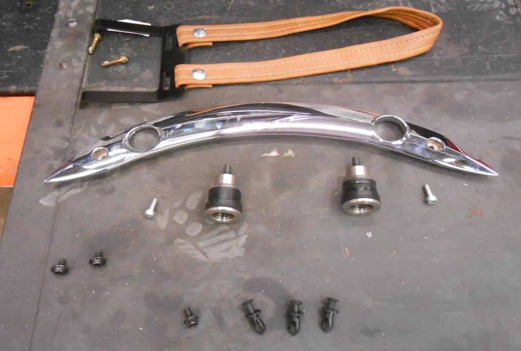
7 Models with Tour Box 5. Remove & Save the Tour Box (10 Fasteners on the floor, two at the rear ((Chrome Bar)) and one wire plug) 6. Remove & Save the Chrome Bar (4 Fasteners) 7. Remove the Quick Disconnect Bracket 8. Remove & Save the Radio Amp and harness 7
8 All Models 9. Remove & Save the Exhaust Heat Shields 10. Remove & Save the Passenger Pegs or Floorboards 11. Remove & Save the Bottom Side Covers 12. Remove & Discard the Rear Highway bars (if equipped) 13. Remove & Save the 4 small triangle shaped black plastic frame covers & fasteners (if equipped) 8
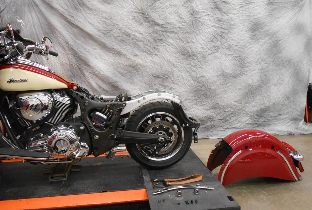
9 14. Remove & Discard the Side stand 15. Remove & Discard the Antenna and its mount 16. Remove & Discard the Mufflers, Saving the Clamps Remove & Discard Rear Fender 17. Unplug Fender wiring plug 18. Remove & Discard the 4 Saddlebag mounting Cylinders 19. Remove Chrome Frame Covers (2 fasteners each) 20. Loosen 4 fasteners inside the rear of fender 21. Remove 2 fasteners in front & 1 on top, on each side 22. Remove Fender 23. Save the two Grommet fasteners on the RT side 24. Remove & Discard the Passenger seat strap(if equipped) 25. Remove & Save the Tip Over Sensor & it s hardware 26. Remove & Discard the plastic inner fender 9
10 10
 31. Remove the nut on the Rear Shock air line 32.")
11 27. Remove the rear caliper (2 fasteners) 28. Remove & Save the rear Wheel Speed Sensor (1 fastener & shim) 29. Remove & Save the Front Sprocket Cover (4 fasteners) 30. Remove & Discard the Rear Shock pivot shaft (Remove snap ring, now thread in a M5 bolt and use it to pull out the shaft) 31. Remove the nut on the Rear Shock air line 32. Remove & Save the Swing Arm Pivot Shaft Remove the left side Nyloc nut, then the Right side Jam Nut & last unthread the Pivot Shaft 33. Remove Drive Belt from front sprocket 11


12 Remove Subframe & Swing Arm 34. Remove the 3 fasteners on the rear of the Battery Box 35. Loosen 5 fasteners on the left side of frame shown in RED Remove 6 fasteners on the rear Subframe shown in BLUE 1 3 on both sides Saving 4 fasteners 37. Spread the frame apart and remove rear Subframe 12

13 38. Remove and discard Swing Arm, wheel, shock & belt as an assembly 13

14 Component Installation 1. Install NEW CSC Belt on Front Sprocket 2. Reinstall the Front Sprocket Cover 3. Lightly tap 2 Hollow Dowels into the upper rear holes of the Upper Cross Brace 4. Install Upper Cross Brace 5. Reinstall 4 OEM fasteners in the upper front and lower rear holes with flat washers and nyloc nuts leave loose 6. Lightly tap the Hollow Dowels into the Motorcycle frame 7. Install 2 M10x70 HHCS with flat washers in the upper rear holes as shown 8. Install 3 1/4-20x3/4 HHCS flat washers & nyloc nuts in the battery box and its cover 9. Reinstall the Grommet fasteners on the right side using an OEM washer & a new washer 14

15 Brake Line Installation 1. Remove & Discard OEM Brake line and caliper 2. Install new CSC Brake line reusing OEM Banjo Bolt with 2 new crush washers 3. Plug in the Wheel Speed Sensor Extension then the OEM Wheel Speed Sensor 4. Leave both the brake line and sensor wire so they go under the Drive Support 15

16 Rear Suspension Unit Installation 1. Position Trike Suspension Unit behind prepared motorcycle frame 2. Install CSC Belt on Drive Sprocket 3. Reinstall the Tip Over Sensor with OEM hardware 4. Install Swing Arm Pivot Shaft & thread it in until you have appox. 1 inch of threads still sticking out on the right side 16
 9.")
17 5. Loosely install the Frame Mounts over the Dowels on the Upper Cross Brace 6. Push Suspension forward to align with Frame Mounts 7. Loosely install 4 3/8 SHCS in the rear of both Frame Mounts 8. Install the Gravel Pan with 5 1/4 HHCS from the bottom up securing with flat washers and nyloc nuts (it may be necessary to pull on Suspension to align Gravel Pan) 9. Install nyloc nuts & flat washers on the 2 M10 & 4 3/8 fasteners on the Frame Mounts 10. Install the CSC Brake Line on the Distribution block with a new Banjo bolt and 2 new crush washers 17
18 11. Tighten Fasteners in this order a. OEM motorcycle frame ( 5 ) b. Upper Cross Brace ( 6 ) c. Rear Frame Mount ( 4 ) d. Gravel Pan ( 5 ) e. OEM Pivot Shaft Tighten until it bottoms out then back it off 1 full turn, tighten the right side Jam Nut, and last tighten the left side Nyloc Nut. After Tightening: There should be appox. 3 threads out on the right side 1-2 threads out on the left side 18

19 Brake Bleeding Procedure 1. Using recommended brake fluid, fill Rear Brake Master Cylinder Reservoir 2. Using a vacuum bleeder, follow this procedure carefully 3. Rear caliper rear bleed valves outsides first then insides on each side 4. Rear caliper front bleed valves outsides first then inside on each side 5. Hand bleed the system using the above sequence until all air is removed from the lines 6. Allow the bike to set for a minimum of 20 minutes and recheck the pedal travel 7. If there is excessive pedal travel on the first pump, repeat steps 3 and 4 8. When complete reinstall the bleeder caps 19

20 ABS Wheel Speed Sensor Installation 1. Install the OEM ABS Wheel Speed Sensor with OEM SHCS and shims if needed (air gap.080 +/-.005) 20

21 Muffler and Tailpipe Installation 1. Install Muffler Mount using three 5/16-18X1 1/4 HHCS, 6 flat washers and 3 nyloc nuts in the lower set of holes 2. If installing the Trailer Hitch Option, install it now 3. Install CSC Tailpipes onto the rear of the OEM head pipes, Reusing the OEM clamps and a new clamp on the lower front mount saddle 4. Install the CSC Muffler onto the tailpipe securing it to the muffler mount with two 5/16-18X3/4 HHCS and flat washers, and to the tailpipe with a clamp 5. Tighten clamps but leave the 2 HHCS securing the mufflers loose to be tightened after the body is installed 21
22 Install the Electric Reverse now if equipped Refer to separate instructions Install the GRD EFX Mounts now if equipped Refer to separate instructions 22
23 Link to CSC Belt Tensioning video Setting up the Sonic Tension Meter 1. Turn power on, Push Select then 1 2. Using the charts below in Front and Rear belt tensioning push Mass, then the numbers, Width and so on 3. For the Rear belt, push Select then 2. Reverse belt can be number 3 and so on Using the Sonic Tension Meter 1. Using the Sonic Tension Meter 2. The microphone placement over the belt is critical a. The microphone should be in the middle of the belt widthwise b. The microphone should be equally in-between the two Sprockets c. The microphone should be between ¼ and ½ an inch above or below the Belt 3. Ensure that the correct setting is displayed on the LCD screen 4. Push MEASURE, then gently tap the Belt with a wrench while holding the microphone in the correct position. A measurement in Lbs. of single span tension should display. If not, continue tightening the Belt until a reading is displayed 5. In noisy environments the Sonic Tension Meter may display errant numbers. If so, use in a quieter area 6. Always take at least THREE readings of the Belt tension and average the THREE readings to determine the actual tension of the Belt 23

24 Tensioning the Front Drive Belt Pivot Shaft Nyloc Nut Four HHCS Clamping HHCS two on each side. 1. With the four HHCS in the rear only on the left side loose. Loosen the four clamping HHCS two per side. 2. Tighten the Rear Drive Belt adjuster nuts until the slack is taken up on the Front Drive Belt. 3. Use the correct setting on the Sonic Tension Meter. MASS 007.9g/m WIDTH mm/r SPAN 0434 mm 4. Check Front Drive Belt tension. 28mm Belt: lbs. of single span tension. 5. Once the correct belt tension is achieved tighten all fasteners loosened or left loose in step 1, Eight HHCS and check the upper pivot shaft nyloc nut. 6. Verify belt tension. NOTE: Belt tension may increase once all bolts are tightened. 24
25 1. See diagram below. Tensioning the Rear Drive Belt 2. Tighten the Rear Drive Belt Adjuster nuts until the slack is taken up on the Rear Drive Belt. 3. Use the correct setting on the Sonic Tension Meter. MASS g/m WIDTH mm/r SPAN 0442 mm 4. Check Rear Drive Belt tension. 50mm belt: lbs. of single span tension. 5. In the next step you are going to run the engine. Please be aware of the safety of all those involved. Make sure you have at least two lug nuts on each brake rotor and that they are tight. 6. To finish alignment, the belt must have visual clearance between edge of belt and fence on front Rear Drive Sprocket. Check this by starting the engine and placing it in second gear and simply let the engine idle. Checking the alignment by eye and centering the belt as it spins. If belt 25
26 has correct clearance, go to step 8. If it does not have clearance, proceed to step Use the Left and Right Rear Drive Belt Adjuster Nuts to align belt in order to achieve the necessary belt clearance. NOTE: The belt will always track to the side of the sprocket that is the loosest. Repeat step Once the correct belt alignment and single span tension is achieved, tighten the eight 5/16 18 x 1 ¼ SHCS that go into the Carrier Bearing Support Housings. 9. Install two 7/16 14 hex jam nuts onto the Rear Drive Belt Tensioning Studs and tighten. 10. Verify belt tension and alignment. 11. If the tension is correct move on to next step. If not, loosen clamping bolts and return to step 4. 26

27 Shock Spring Preloader Installation 1. Raise the Preload adjuster into the bracket as shown and secure with X 1 BHSCS 27
28 250 LB/IN SPRING 300 LB/IN SPRING 350 LB/IN SPRING Suspension Setup Use this chart to select the correct spring preload. Rotate the adjuster nut on the shock until the spring is set to the desired length. Now tighten the set screw on the adjuster nut, but do not over tighten. Load: Typical weight the customer adds to the trike. This includes riders, luggage, and weight of a trailer tongue. When in doubt assume a higher weight than actual. Length: Suggested length the spring should be adjusted to with the suspension completely unloaded, rear tires in the air, and the Preloader adjusted all the way out ARROW SHOCK with RED SPRING LOAD LENGTH LOAD LENGTH LOAD LENGTH / / / / / / / / / / / / / / / / / / /8 28
29 These lengths are only estimates. If you would like to confirm a correct setting, load the completed trike to the customer s typical riding situation and measure from the ground to the middle of the lower suspension plate. The center hole should be from the ground. Attention: This is the only suspension adjustment needed. All other settings are factory set and should not be tampered with. There is no need to remove trike from the lift to check camber, toe, or the drop links

30 Trike Body Installation 1. Install OEM left lower Side Cover (3 fasteners) Road Master Models only: 2. Install Amp on CSC bracket new fasteners & nyloc nuts 3. Lower the Amp into place into the body securing with S.S. BHCS, washers & nyloc nuts Wires shown below are after the Tour Box is installed 4. Remove 4 hitch pins in order to remove the Wheel Skirts 5. Remove the Wheel Skirts 6. Lower the body onto the trike with the body lever until it comes to rest onto the upper tray and body frame 30


31 7. It will be necessary to grind the right lower Side Cover Cut on Dotted line as shown Before After 31

32 Trike Body Alignment 1. The Trike Body can move left, right, forward, backward, up, down, and angled. Shimming with the provided 1/4 and 1/8 Rubber Washers may be required to get the Trike Body into alignment 2. Now with all 4 Side Covers installed 3. Raise the front of the body to align with the Side Covers to allow for an even gap 4. With the body temporarily held into place, raise the adjustable 90 body support brackets until they seat against the body s inner liner, Tighten the two 5/16 18 x 3/4 HHCS and nyloc nuts on the Adjustable 90 Support Brackets 5. Align the muffler with the muffler cutout in the body 6. Center the Trike Body left to right measuring off the rotors with a carpenters square 7. Reinstall the Exhaust Heat Shields 32
33 Securing the Trike Body Note: A small section of Trike Body Carpet has not been glued at the location of the Trike Body Frame mounting tabs to allow removal of the bolts used in shipping, and installation of the Trike Body mounting hardware. The predrilled bolt holes may need to be enlarged or relocated for Trike Body attachment to the Trike Body Frame mounting tabs. If relocation is necessary, the preexisting holes will need to be sealed with silicone sealant. 1. Using a 5/16 twist drill, drill up through the Trike Body Frame mounting tabs 2. Insert 5/16 18 x 1 1/4 HHCS, fender washer, and rubber washers if necessary through the holes drilled 3. Install nyloc nuts and flat washers onto the rear HHCS and tighten 4. Using a 5/16 twist drill, drill up through the Adjustable 90 Body Support Brackets 5. Insert 5/16 18 x 1 1/4 HHCS and fender washers through the adjustable 90 body support brackets. 6. Install nyloc nuts and flat washers onto the front HHCS and tighten 7. Re-align the Mufflers and tighten hardware 8. Reinstall the 4 triangle shaped black plastic frame covers 9. Use silicone to seal the shipping holes and to glue the carpet down 33


34 Tour Box Installation 1. Lower the Tour Box in place on the body 2. Install 4 5/16x2 1/4 HHCS with flat washers in the center of the Tour Box, Secure with fender washers & nyloc nuts inside the body & tighten 3. Cut the Chrome bar as shown appox. 7 inches from the front of the bar 4. Install 2 well nuts in the cut end of the Chrome Bar 5. Install the cut Chrome Bar with 2 5/16x1 3/4 HHCS, flat washers & the 2 OEM fasteners & washers & tighten 6. Install 4 more 5/16x2 1/4 HHCS with fender washers in the perimeter holes inside the Tour Box now secure with fender or flat washer & tighten 34

35 7. Plug in the Tour Box harness to the Amp, now remove the wire extension from the seat and plug it into the Tour Box and the Motorcycle harness, then secure it 8. Reinstall the OEM liner 35
36 Final Assembly 1. Connect the fender plug to the trike body plug 2. Connect the RED fusable link to the positive battery post and the White wire to the negative 3. Reinstall the wheel and tire assemblies with ten m12 x 1.5 ET conical lug nuts. Torque to 75 FT-LBS 4. Reinstall the Wheel Skirts & secure them with 4 hitch pins 5. Recommended tire pressure 15 & 16 wheels 28 psi 17 wheels 25 psi From all of us at California Sidecar. Enjoy the ride. 36
Installation Instructions
 BY Trike Conversion Kit KAWASAKI Vulcan 900 CLASSIC- CLASSIC LT AND CUSTOM MODELS 2006-CURRENT Installation Instructions Revised 1-2015 California Sidecar Parts & Technical Support 434.263.8866 2 Table
Current. Installation Instructions
 by Trike Conversion Kit 2004 - Current Harley-Davidson Sportster Installation Instructions REVISED 4-2017 California Sidecar Parts & Technical Support 434.263.8866 Table of contents: 1. Warnings and Considerations
Trike Conversion Kit ROADLINER, STRATOLINER, & STRATOLINER DELUXE
 by Trike Conversion Kit ROADLINER, STRATOLINER, & STRATOLINER DELUXE Installation Instructions Revised 1-2015 California Sidecar Parts & Technical Support 434.263.8866 Table of Contents: 1. Warnings and
Victory CrossRoads CrossCountry CrossCountry Tour HardBall
 by Trike Conversion Kit Victory CrossRoads CrossCountry CrossCountry Tour HardBall Installation Instructions Revised 3-2018 California Sidecar Parts & Technical Support 434.263.8866 Table of Contents:
Trike Conversion Kit. KAWASAKI 1700 Vulcan Voyager Vulcan Vaquero Vulcan Nomad. Installation Instructions
 BY Trike Conversion Kit KAWASAKI 1700 Vulcan Voyager Vulcan Vaquero Vulcan Nomad Installation Instructions REVISED 1-2015 California Sidecar Parts & Technical Support 434.263.8866 Table of Contents: 1.
Trike Conversion Kit GL1500 Goldwing
 BY Trike Conversion Kit 1988-2000 GL1500 Goldwing Installation Instructions Revised 3-2018 California Sidecar Parts & Technical Support 434.263.8866 Table of contents: 1. Maintenance Schedule 5 2. Disassembly
Installation Instructions
 BY Trike Conversion Kit 2009 - Current FLHT Series Harley-Davidson Installation Instructions REVISED 7-2017 California Sidecar Parts & Technical Support 434.263.8866 2 Table of contents: 1. Warnings and
2018 UP GL1800 Gold Wing & Gold Wing Tour. Trike Kit Installation Instructions. California Sidecar Parts & Technical Support
 by 2018 UP GL1800 Gold Wing & Gold Wing Tour Trike Kit Installation Instructions California Sidecar Parts & Technical Support 434.263.8866 2 Table of contents: 1. Maintenance Schedule 5 2. Disassembly
Installation Instructions
 BY Trike Conversion Kit 1999 2008 FLHT Series Harley-Davidson Installation Instructions REVISED 4-2017 California Sidecar Parts & Technical Support 434.263.8866 Table of contents: 1. Warnings and considerations
Trike Conversion Kit GL1800 Goldwing Current. Installation Instructions
 by Trike Conversion Kit GL1800 Goldwing 2012 - Current Installation Instructions REVISED 4-2015 California Sidecar Parts & Technical Support 434.263.8866 Table of contents: 1. Maintenance Schedule 5 2.
Cobra & Cobra XL. Trike Conversion Kit GL1800 Goldwing. Installation Instructions. California Sidecar Parts & Technical Support
 Cobra & Cobra XL by Trike Conversion Kit 2001-2010 GL1800 Goldwing Installation Instructions REVISED 1-2015 California Sidecar Parts & Technical Support 434.263.8866 Table of contents: 1. Maintenance Schedule
CALIFORNIA SIDECAR TRIKE CONVERSION KIT INSTALLATION INSTRUCTIONS VALKYRIE INTERSTATE
 CALIFORNIA SIDECAR TRIKE CONVERSION KIT INSTALLATION INSTRUCTIONS VALKYRIE INTERSTATE FOR INSTALLATION ASSISTANCE, CALL PARTS & TECHNICAL SUPPORT @ (434) 263-8866 TABLE OF CONTENTS SECTION PAGE Table of
Installation Instructions
 By ELECTRIC REVERSE INDIAN MOTORCYCLES CLASSIC - VINTAGE - DARKHORSE CHIEFTAN & ROADMASTER MODELS 2014 - CURRENT Revised 10-2018 Installation Instructions California Sidecar Parts & Technical Support 434.263.8866
2018 UP GL1800 Gold Wing & Gold Wing Tour. Power Trak Installation Instructions. California Sidecar Parts & Technical Support
 by 2018 UP GL1800 Gold Wing & Gold Wing Tour Power Trak Installation Instructions California Sidecar Parts & Technical Support 434.263.8866 Warnings and considerations: 1. Disclaimer - These instructions
Trike Conversion Installation Guide Kawasaki Vulcan 900 Classic, Classic LT, and Custom Models 2007 and Up Solid Axle Suspension
 Trike Conversion Installation Guide Kawasaki Vulcan 900 Classic, Classic LT, and Custom Models 2007 and Up Solid Axle Suspension CAUTION: -Failure to make the proper adjustments will potentially lead to
Cobra & Cobra XL. Power Trak Current GL1800 Goldwing. Installation Instructions. California Sidecar Parts & Technical Support
 Cobra & Cobra XL by 2001 - Current GL1800 Goldwing Power Trak 6 Installation Instructions REVISED 1 2015 California Sidecar Parts & Technical Support 434.263.8866 Warnings and considerations: 1. Disclaimer
2018 UP GL1800 Gold Wing & Gold Wing Tour. Auxiliary Fuel Tank. Installation Instructions
 by 2018 UP GL1800 Gold Wing & Gold Wing Tour Auxiliary Fuel Tank Installation Instructions California Sidecar Parts & Technical Support 434.263.8866 Warnings and considerations: 1. Disclaimer - These instructions
ELECTRIC REVERSE Installation Instructions
 BY 1999 - Current FLHT Series Harley-Davidson ELECTRIC REVERSE Installation Instructions REVISED 1-2016 California Sidecar Parts & Technical Support 434.263.8866 Warnings and considerations: 1. Disclaimer
Trike Conversion Installation Guide for Indian Scout Motorcycles 2016 & Up Revision 2
 Trike Conversion Installation Guide for Indian Scout Motorcycles 2016 & Up Revision 2 Warning - This product was not intended for more than one rider. Weight limit on this product has been set at 400 lbs.
ELECTRIC REVERSE Current. Harley-Davidson Sportster. Installation Instructions
 By ELECTRIC REVERSE 2004 - Current Harley-Davidson Sportster Installation Instructions California Sidecar Parts & Technical Support 434.263.8866 Warnings and considerations: 1. Disclaimer - These instructions
2010+ Victory Cross Country / Cross Roads Installation Guide Nov 2014
 2010+ Victory Cross Country / Cross Roads Installation Guide Nov 2014 125 Industrial Drive Spearfish, SD 57783 Toll Free 888.3WHEELS w w w. l e h m a n t r i k e s. c o m UNDERSTANDING SAFETY LABELS &
R O A D S M I T H TRIKE CONVERSIONS BY THE TRIKE SHOP
 R O A D S M I T H TRIKE CONVERSIONS BY THE TRIKE SHOP Please thoroughly review the instructions before and during installation. Keep in mind that this product was designed to be installed by trained dealer
-Failure to make the proper adjustments will potentially lead to serious personal injury and/or property damage and may void the warranty.
 Trike Conversion Installation Guide Victory Cross Roads Classic and 8-Ball Victory Cross Country/Tour/8-Ball and Ness Cross Country Limited-Edition and Up Independent Suspension Rev. 1 CAUTION: -Failure
CALIFORNIA SIDECAR TRIKE CONVERSION KIT INSTALLATION INSTRUCTIONS MODEL YEARS. For installation assistance, call Parts & Technical iii PAGE
 CALIFORNIA SIDECAR TRIKE CONVERSION KIT INSTALLATION INSTRUCTIONS GOLD WING 1500 1988-2000 MODEL YEARS For installation assistance, call Parts & Technical Support @ (434) 263-8866 SECTION TABLE OF CONTENTS
R O A D S M I T H TRIKE CONVERSIONS BY THE TRIKE SHOP
 R O A D S M I T H TRIKE CONVERSIONS BY THE TRIKE SHOP Please thoroughly review the instructions before and during installation. Keep in mind that this product was designed to be installed by trained dealer
Trike Conversion Installation Guide for Harley-Davidson Sportster Motorcycles 2004 & Up Revision 7
 Trike Conversion Installation Guide for Harley-Davidson Sportster Motorcycles 2004 & Up Revision 7 CAUTION : Failure to follow these instructions can lead to serious personal injury and/or property damage
INSTALLATION INSTRUCTION 88581
 INSTALLATION INSTRUCTION 88581 FOR RANCHO SUSPENSION SYSTEM RS6581B: DODGE RAM READ ALL INSTRUCTIONS THOROUGHLY FROM START TO FINISH BEFORE BEGINNING INSTALLATION Rev C IMPORTANT NOTES! WARNING: This suspension
RAIDER to 2016 XL MODELS *Will not fit XR1200 models *Nightster, Forty-Eight and Iron 883 models may require additional modifications
 RAIDER 2014 to 2016 XL MODELS *Will not fit XR1200 models *Nightster, Forty-Eight and Iron 883 models may require additional modifications **Installation should be installed by a qualified mechanic INSTALLATION
R O A D S M I T H TRIKE CONVERSIONS BY THE TRIKE SHOP
 R O A D S M I T H TRIKE CONVERSIONS BY THE TRIKE SHOP Please thoroughly review the instructions before and during installation. Keep in mind that this product was designed to be installed by trained dealer
INSTALLATION INSTRUCTION 89400
 INSTALLATION INSTRUCTION 89400 FOR RANCHO SUSPENSION SYSTEM RS66400B: 2012 RAM 1500 4WD. READ ALL INSTRUCTIONS THOROUGHLY FROM START TO FINISH BEFORE BEGINNING INSTALLATION Rev B IMPORTANT NOTES! WARNING:
R O A D S M I T H TRIKE CONVERSIONS BY THE TRIKE SHOP
 R O A D S M I T H TRIKE CONVERSIONS BY THE TRIKE SHOP Please thoroughly review the instructions before and during installation. Keep in mind that this product was designed to be installed by trained dealer
INSTALLATION INSTRUCTION Rev A
 INSTALLATION INSTRUCTION 88587 Rev A FOR RANCHO SUSPENSION SYSTEM RS6587B: 2009 DODGE RAM 1500 READ ALL INSTRUCTIONS THOROUGHLY FROM START TO FINISH BEFORE BEGINNING INSTALLATION IMPORTANT NOTES! WARNING:
Trike Conversion Installation Manual. All Models
 Trike Conversion Installation Manual For Honda VTX 1300 Motorcycles All Models Revision 4 Mar. 2011 CAUTION: Failure to follow these instructions can lead to serious personal injury and/or property damage
Suspension System RS6582B
 Suspension System RS6582B Tahoe/Yukon READ ALL INSTRUCTIONS THOROUGHLY FROM START TO FINISH BEFORE BEGINNING INSTALLATION IMPORTANT NOTES! WARNING: This suspension system will enhance the off-road performance
INSTALLATION INSTRUCTIONS 88043
 INSTALLATION INSTRUCTIONS 88043 FOR RANCHO SUSPENSION SYSTEM RS6543: CHEVROLET K1500 READ ALL INSTRUCTIONS THOROUGHLY FROM START TO FINISH BEFORE BEGINNING INSTALLATION Rev E IMPORTANT NOTES! WARNING:
INSTALLATION INSTRUCTION 88088
 INSTALLATION INSTRUCTION 88088 For Rancho Suspension Systems RS6588 & RS6589: FORD F-150 READ ALL INSTRUCTIONS THOROUGHLY FROM START TO FINISH BEFORE BEGINNING INSTALLATION Rev B IMPORTANT NOTES! WARNING:
R O A D S M I T H TRIKE CONVERSIONS BY THE TRIKE SHOP
 R O A D S M I T H TRIKE CONVERSIONS BY THE TRIKE SHOP Please thoroughly review the instructions before and during installation. Keep in mind that this product was designed to be installed by trained dealer
INSTALLATION INSTRUCTION 88073
 INSTALLATION INSTRUCTION 88073 Rev C FOR RANCHO SUSPENSION SYSTEMS RS6572 & RS6573: DODGE RAM READ ALL INSTRUCTIONS THOROUGHLY FROM START TO FINISH BEFORE BEGINNING INSTALLATION IMPORTANT NOTES! WARNING:
INSTALLATION INSTRUCTIONS FOR THE MOTOR TRIKE CROSS COUNTRY / CROSS ROADS / HARD BALL RAKE KIT
 INSTALLATION INSTRUCTIONS FOR THE MOTOR TRIKE CROSS COUNTRY / CROSS ROADS / HARD BALL RAKE KIT Thank you for choosing the Motor Trike Cross Country / Cross Roads / Hard Ball rake kit. We ask that you read
INSTALLATION INSTRUCTION 88581
 INSTALLATION INSTRUCTION 88581 FOR RANCHO SUSPENSION SYSTEM RS6581B: DODGE RAM READ ALL INSTRUCTIONS THOROUGHLY FROM START TO FINISH BEFORE BEGINNING INSTALLATION Rev D IMPORTANT NOTES! WARNING: This suspension
R O A D S M I T H TRIKE CONVERSIONS BY THE TRIKE SHOP
 R O A D S M I T H TRIKE CONVERSIONS BY THE TRIKE SHOP Please thoroughly review the instructions before and during installation. Keep in mind that this product was designed to be installed by trained dealer
Trike Conversion Installation Guide for Zero Flex Solid Axle Wide Body Harley-Davidson FLH Series Motorcycles Revision 1
 Trike Conversion Installation Guide for Zero Flex Solid Axle Wide Body Harley-Davidson FLH Series Motorcycles 2014-2016 Revision 1 WARNING: Failure to follow these instructions can lead to serious personal
Current Softail FLST Harley-Davidson. Ground Effects Installation Instructions
 by 2000 - Current Softail FLST Harley-Davidson Ground Effects Installation Instructions Revised 1-2015 California Sidecar Parts & Technical Support 434.263.8866 Notice to installers 2007 and newer bikes
TOYOTA COROLLA LOWERING SPRINGS Preparation
 Preparation Part Number: PTR07-02140 Kit Contents Item # Quantity Reqd. Description 1 2 Front Spring 2 2 Rear Spring 3 1 Hardware 4 1 Instruction Form Hardware Bag Contents Item # Quantity Reqd. Description
INSTALLATION INSTRUCTION 88094
 INSTALLATION INSTRUCTION 88094 FOR RANCHO SUSPENSION SYSTEM RS6594B 4WD & 2WD NISSAN TITAN READ ALL INSTRUCTIONS THOROUGHLY FROM START TO FINISH BEFORE BEGINNING INSTALLATION Rev D IMPORTANT NOTES! WARNING:
Installation Guide. Yamaha. 40 Sport Trike Kit All Years
 Installation Guide Yamaha 40 Sport Trike Kit All Years INCLUDED IN YOUR TRIKE KIT: COMPONENTS Frankenstein Trikes Rear End Swing Arm Body Body Mounting Bracket 10 lug nuts 1 2 American Eagle 15 X 8 wheels
INSTALLATION PROCESS: FK003D945-7 Complete Front, Rear, and Clutch A.B.S. KIT Harley Davidson FLH Touring Models
 INSTALLATION PROCESS: FK003D945-7 Complete Front, Rear, and Clutch A.B.S. KIT 2014-2017 Harley Davidson FLH Touring Models Parts List: 4 Lines 1 Brake Light Switch Adapter 7 Single banjo bolts 2 Caliper
INSTALLATION INSTRUCTIONS 88043
 INSTALLATION INSTRUCTIONS 88043 FOR SUSPENSION SYSTEM RS6543: CHEVROLET K1500 Rev B READ ALL INSTRUCTIONS THOROUGHLY FROM START TO FINISH BEFORE BEGINNING INSTALLATION IMPORTANT NOTES! A. The vehicle s
Detroit Speed, Inc. Rear QUADRAlink Conversion Kit Camaro/Firebird P/N:
 Detroit Speed, Inc. Rear QUADRAlink Conversion Kit 1982-92 Camaro/Firebird P/N: 041721 The Detroit Speed Inc. QUADRAlink Conversion Kit, eliminates the factory torque arm configuration. It features no-compromise
Installation Guide. Sportster 34 Sport Trike Kit
 Installation Guide Sportster 34 Sport Trike Kit INCLUDED IN YOUR TRIKE KIT: COMPONENTS HARDWARE PULLEY MOUNTING 5 pcs. - 7/16-14 x 1 ½ Grd. 8 (Gold) Bolt 5 pcs. - 7/16 Lock Washer 34 Light Sport Rear End
INSTALLATION INSTRUCTIONS 8827
 INSTALLATION INSTRUCTIONS 8827 FOR SUSPENSION SYSTEM RS6427: CHEVEROLET K1500 READ ALL INSTRUCTIONS THOROUGHLY FROM START TO FINISH BEFORE BEGINNING INSTALLATION Rev A IMPORTANT NOTES! A. Before installing
INSTALLATION INSTRUCTIONS FOR THE TOMAHAWK ELECTRIC REVERSE
 INSTALLATION INSTRUCTIONS FOR THE TOMAHAWK ELECTRIC REVERSE LAST UPDATED: April 2018 Thank you for choosing the Motor Trike Electric Reverse. We ask that you read the directions before you start and follow
Always wear safety glasses when working on your vehicle.
 90-93 MAZDA MIATA SUPERCHARGER KIT The KraftWerks 90-93 Mazda Miata Supercharger Kit was designed for easy installation. Competent mechanics with the appropriate tools will find the process to be relatively
INSTALLATION INSTRUCTION 88146
 INSTALLATION INSTRUCTION 88146 Rev H FOR RANCHO SUSPENSION SYSTEM RS6547: 4WD SUBURBAN/YUKON XL, 4WD TAHOE/YUKON, & 4WD AVALANCHE READ ALL INSTRUCTIONS THOROUGHLY FROM START TO FINISH BEFORE BEGINNING
INSTALLATION INSTRUCTION 88148
 INSTALLATION INSTRUCTION 88148 Rev C For Rancho Suspension Systems RS6548, RS6549 & RS6550: GM 2500HD, 2500, and 1500HD Trucks READ ALL INSTRUCTIONS THOROUGHLY FROM START TO FINISH BEFORE BEGINNING INSTALLATION
P/N Instr Rev Page 1 of 11
 BRAKE AND CLUTCH KIT P/N 2883864 IMPORTANT Due to the technical nature of this kit, Indian Motorcycle insists this installation be performed by a certified Indian Motorcycle Technician. APPLICATION Verify
'99-03 CHEVROLET/GMC IFS 4WD 6" SUSPENSION SYSTEM P/N INSTALLATION INSTRUCTIONS
 1/16/04 '99-03 CHEVROLET/GMC IFS 4WD 6" SUSPENSION SYSTEM P/N. 10-41099 INSTALLATION INSTRUCTIONS NOTE: Each Lift Kit and options to Lift Kits are packaged separately. Therefore, installation procedures
Installation Instructions
 Installation Instructions CUSTOM QUICK INSTALL MOUNTING KIT 2011 & UP Ford Super Duty F-250/F-350/F-50 2011 & UP Part Number: 50073 WARNING: Under no circumstances do we recommend exceeding the towing
1 Part Number: M-2300-Y Part Description: S550 Mustang-Shelby Brake Upgrade Kit Installation Instructions
 Please visit www.performanceparts.ford.com for the most current instruction and warranty information. PLEASE READ ALL OF THE FOLLOWING INSTRUCTIONS CAREFULLY PRIOR TO INSTALLATION. AT ANY TIME YOU DO NOT
INSTALLATION INSTRUCTIONS
 INSTALLATION INSTRUCTIONS FORCE 10 SPORT R1 REAR DISC CONVERSION KIT A126-50 2005-10 Chevrolet Silverado and GMC Sierra Thank you for choosing STAINLESS STEEL BRAKES CORPORATION for your braking needs.
Installation Notes: #86000-R Race Series +3.5 L/T Kit
 159 North Maple St. Unit J, CORONA CA 92880 P. 951-737-9682 F. 951-737-9006 WWW.CHAOSFAB.COM Installation Notes: #86000-R Race Series +3.5 L/T Kit Factory manual is recommended for removal and re-installation
2017 Current Ford Raptor HoneyBadger Rear Bumper Installation Instructions
 2017 Current Ford Raptor HoneyBadger Rear Bumper Installation Instructions PREPARATION 1. Disconnect the negative terminal on the battery. Park the vehicle on level ground and set the emergency brake.
DISC BRAKE/DUAL MASTER CYLINDER CONVERSION. Tools, Equipment and Supplies Needed:
 Please take the time to read the enclosed instructions carefully. If you have any questions, call our Product Assistance personnel for clarification. It is important to note that these instructions contain
Flt/Flh Road King 38 Sport Trike Kit. Installation Guide
 Flt/Flh Road King 38 Sport Trike Kit Installation Guide INCLUDED IN YOUR TRIKE KIT: COMPONENTS HARDWARE 38 Sport Std. Rear End Swing Arm PULLEY MOUNTING 5 pcs. - 7/16-14 x 2 Grd. 8 (Gold) Bolt (2000 &
Installation Guide. Yamaha Bolt. 36 Light Sport 200 Trike Kit. All Years
 Installation Guide Yamaha Bolt 36 Light Sport 200 Trike Kit All Years INCLUDED IN YOUR TRIKE KIT: COMPONENTS Frankenstein Trikes Rear End Swing Arm 2 Fenders 2 Fender Brackets 10 lug nuts 1 2 Pacer 15
LEXUS IS 250 Front Performance Brake Kit Section I - Installation Preparation
 LEXUS IS 250 Front 2006- Performance Brake Kit Section I - Installation Preparation Part Number: PTR09-53080 Kit Contents Item # Quantity Reqd. Description 1 1 Brake Rotor, LH Front 2 1 Brake Rotor, RH
INSTALLATION INSTRUCTIONS FOR THE MOTOR TRIKE GL1500 RAKE KIT
 INSTALLATION INSTRUCTIONS FOR THE MOTOR TRIKE GL1500 RAKE KIT Thank you for choosing the Motor Trike GL1500 Rake Kit. We ask that you read the directions before you start and follow them very closely.
INSTALLATION INSTRUCTION 88051
 INSTALLATION INSTRUCTION 88051 For Rancho Suspension System RS6551: Chevrolet 2500 Suburban & 2500 Avalanche READ ALL INSTRUCTIONS THOROUGHLY FROM START TO FINISH BEFORE BEGINNING INSTALLATION Rev C IMPORTANT
2010 INDIAN MOTORCYCLE PRE- DELIVERY AND INSPECTION
 2010 INDIAN MOTORCYCLE PRE- DELIVERY AND INSPECTION Table of Contents Introduction 1 Preparing the motorcycle.... 2 Pre-Delivery Checklist...... 4 Customer Acceptance........ 6 Introduction For your own
SCION tc LOWERING SPRINGS Preparation
 Preparation Part Number: PTR11-21100 PTR11-21100-50 Kit Contents Item # Quantity Reqd. Description 1 2 Front Spring 2 2 Rear Spring 3 2 Locking Nut 4 2 Spring Bumper, Front 5 1 Instruction Form Hardware
INSTALLATION INSTRUCTIONS
 INSTALLATION INSTRUCTIONS REAR DISC BRAKE CONVERSION KIT A126-1 1973-87 CHEVROLET 1/2 TON 2WD Thank you for choosing STAINLESS STEEL BRAKES CORPORATION for your braking needs. Pleases take the time to
INSTALLATION INSTRUCTION 88554
 INSTALLATION INSTRUCTION 88554 Rev B For Rancho Non-Torsion Bar Drop Suspension System RS6554B: GM 2500HD. READ ALL INSTRUCTIONS THOROUGHLY FROM START TO FINISH BEFORE BEGINNING INSTALLATION Ultra Wheels
Champion Trikes. EZ-Steer Installation Guide For 2007-Up Kawasaki Vulcan 900 Motorcycles Classic, Classic LT, and Custom Models
 Champion Trikes For 2007-Up Kawasaki Vulcan 900 Motorcycles Note: Above CAD picture is for illustrative purposes to show main components of EZ Steer. Champion Motorcycle Accessories International, Inc.
Sportster 34 Sport Trike Kit
 Sportster 34 Sport Trike Kit INCLUDED IN YOUR TRIKE KIT: COMPONENTS HARDWARE PULLEY MOUNTING 5 pcs. - 7/16-14 x 1 ½ Grd. 8 (Gold) Bolt 5 pcs. - 7/16 Lock Washer 34 Light Sport Rear End FENDER MOUNTING
INSTALLATION PROCESS: FK003D744 Complete Brake Line Kit VFR800 NON ABS
 INSTALLATION PROCESS: FK003D744 Complete Brake Line Kit 2000-2007 VFR800 NON ABS Step 1: Identify the key components that complete our brake line kit: You should have Ten (10) hoses, one (1) double banjo
INSTALLATION INSTRUCTIONS 88518
 INSTALLATION INSTRUCTIONS 88518 For Rancho Suspension Systems RS6518: 2009 FORD F-150 4WD READ ALL INSTRUCTIONS THOROUGHLY FROM START TO FINISH BEFORE BEGINNING INSTALLATION Rev A IMPORTANT NOTES! WARNING:
KIT # CSS-C SUSPENSION LIFT KIT
 14385 Veterans Way Moreno Valley, CA 92553 Phone: (951) 571-0212 Fax: (951) 571-0215 2001-2010 CHEVROLET SILVERADO 1500 AND 2500 HD 4WD AND 2WD PICK-UP 1999-2010 CHEVY 2500 4WD PICK-UPS 2001-2010 2500
Tools, Equipment and Supplies Needed:
 153-162 DISC BRAKE/DUAL MASTER CYLINDER CONVERSION Please take the time to read the enclosed instructions carefully. If you have any questions, call our Product Assistance personnel for clarifi cation.
Jeep Wrangler (JK) Present
 Present") 89107 Rev H Suspension System RS66107 / RS66107B (3 TRAIL SYSTEM) 2012 NEWER JEEP MODELS EQUIPPED WITH 3.6L V6 ENGINE NEED EXHAUST MODIFICATION KIT RS720003. OR REPLACEMENT FRONT DRIVESHAFT (DRIVESHAFT
89107 Rev H Suspension System RS66107 / RS66107B (3 TRAIL SYSTEM) 2012 NEWER JEEP MODELS EQUIPPED WITH 3.6L V6 ENGINE NEED EXHAUST MODIFICATION KIT RS720003. OR REPLACEMENT FRONT DRIVESHAFT (DRIVESHAFT
INSTALLATION INSTRUCTIONS 88056
 INSTALLATION INSTRUCTIONS 88056 FOR RANCHO ROCK CRAWLER SUSPENSION SYSTEM RS6506: JEEP WRANGLER (TJ) Rev B READ ALL INSTRUCTIONS THOROUGHLY FROM START TO FINISH BEFORE BEGINNING INSTALLATION IMPORTANT
INSTALLATION INSTRUCTIONS 88029
 INSTALLATION INSTRUCTIONS 88029 FOR SUSPENSION SYSTEMS RS6503: JEEP WRANGLER (TJ) READ ALL INSTRUCTIONS THOROUGHLY FROM START TO FINISH BEFORE BEGINNING INSTALLATION REV F IMPORTANT NOTES! WARNING: This
Detroit Speed, Inc. Detroit Speed Control Arm and Spindle Kit A-Body P/N: &
 Detroit Speed, Inc. Detroit Speed Control Arm and Spindle Kit 1964-72 A-Body P/N: 030104 & 030105 The Detroit Speed A-Body front suspension kit is a bolt-on package that addresses the shortcomings of the
REMOVAL & INSTALLATION
 REMOVAL & INSTALLATION FRONT DISC BRAKE PADS 1. Raise and support front of vehicle. Remove wheels. Remove caliper bolt and brakeline bracket bolts. Pivot caliper aside. Remove pads and pad shim. Remove
CHAINGUARD REGAL ST COLOR
 DESOTO/ REGAL HAULER PARTS LIST Item Part # Description QTY Item Part # Description QTY 1 11871 REFLECTOR KIT TRIKE 1 32 11764 FENDER BRACE 24" MWT 1 2 12199 SCREW #14 x 3/4 4 33 12176 NUT5/16-24 HEX 2
2018 MotoTrax. Track Kit Installation Manual
 2018 MotoTrax Track Kit Installation Manual 1 Preparing the bike 1) Put the motorcycle on a stand. 2) Remove stock drive chain 3) Remove the rear wheel 4) Remove the mud flap 5) Disconnect the suspension
Installation Instructions
 Installation Instructions Jeep TJ Long Arm Suspension System 1997-2002 JEEP TJ 4WD 6 1997-2002 JEEP TJ 4WD FTS24002 & BK / FTS24003 & BK / FTS44002 & BK PARTS LIST FTS24002BK Jeep TJ 6' Box Kit 1 FTS24003BK
Go-ped ESR750 / ESR750EX Rear Brake Installation Instructions
 Go-ped ESR750 / ESR750EX Rear Brake Installation Instructions This kit provides all the parts you need to install a rear brake on your ESR750 or ESR750EX. It will not work on an ESR Sport, or other Go-ped
07-UP AVALANCHE 7.5 KIT
 92120900R1 07-UP AVALANCHE 7.5 KIT Thank you for choosing Rough Country for your suspension needs. We appreciate your business!! This kit will not fit vehicles equipped with electric steering or trucks
TOYOTA TACOMA LED DRL Black-Out
 TOYOTA TACOMA 2013 - LED DRL Black-Out Part Number: 00016-35021 Accessory Code: LDBO10 Conflicts - Fog Lights Kit Contents Item # Quantity Reqd. Description 1 2 DRL Housing 2 1 Driver Box 3 1 Harness bag
INSTALLATION INSTRUCTIONS
 INSTALLATION INSTRUCTIONS REAR DISC CONVERSION KIT A128 1990-1995 JEEP WRANGLER (YJ) WITH DANA 35 AXLES (non-abs) Thank you for choosing STAINLESS STEEL BRAKES CORPORATION for your braking needs. Pleases
INSTALLATION INSTRUCTIONS
 INSTALLATION INSTRUCTIONS REAR DISC CONVERSION KIT A126-2 1988-98 C1500 2WD 10" REAR DRUM Thank you for choosing STAINLESS STEEL BRAKES CORPORATION for your braking needs. Pleases take the time to read
AEV30308AA Last Updated: 05/31/18. 4 DUALSPORT sc SUSPENSION system for RAM 1500 air ride standard and rebel INSTALLATION GUIDE
 AEV30308AA Last Updated: 05/31/18 4 DUALSPORT sc SUSPENSION system for RAM 1500 air ride standard and rebel INSTALLATION GUIDE PLEASE READ BEFORE YOU START TO GUARANTEE A QUALITY INSTALLATION, WE RECOMMEND
TOYOTA TUNDRA BIG BRAKE KIT Section I - Installation Preparation
 TOYOTA TUNDRA 2007- BIG BRAKE KIT Section I - Installation Preparation Part Number: PTR09-34070 Kit Contents Item # Quantity Reqd. Description 1 1 Brake Rotor, LH Front 2 1 Brake Rotor, RH Front 3 1 Brake
CHAINGUARD REGAL ST COLOR
 DESOTO/ REGAL HAULER PARTS LIST Item Part # Description QTY Item Part # Description QTY 1 11871 REFLECTOR KIT TRIKE 1 32 11762 FENDER BRACE 20" MWT 1 2 12199 SCREW #14 x 3/4 4 11764 FENDER BRACE 24" MWT
'88-'00 CHEVROLET/GMC IFS 4WD(8LUG) OLD BODY STYLE 6" SUSPENSION SYSTEM P/N
 OLD BODY STYLE 6 SUSPENSION SYSTEM P/N") 4/10/13 '88-'00 CHEVROLET/GMC IFS 4WD(8LUG) OLD BODY STYLE 6" SUSPENSION SYSTEM P/N. 10-41888 INSTALLATION INSTRUCTIONS APPLICATION WARNING: Applicable for hub mounted ABS sensor models only. Not for 1992-94
4/10/13 '88-'00 CHEVROLET/GMC IFS 4WD(8LUG) OLD BODY STYLE 6" SUSPENSION SYSTEM P/N. 10-41888 INSTALLATION INSTRUCTIONS APPLICATION WARNING: Applicable for hub mounted ABS sensor models only. Not for 1992-94
Slave Cylinder Weep Hole Drilling Procedure
 Slave Cylinder Weep Hole Drilling Procedure Tools Required: T20 Torx Driver T25 Torx Driver T25 Torx Bit with ¼ Ratchet Wrench 4mm Hex Key (Allen wrench) 5mm Hex Key 6mm Hex Key 8mm Hex Key 12mm Hex Key
»Product» Safety Warning
 D9151 Installation Instructions 2006-2008 Dodge Ram 1500 1.5" Body Lift Read and understand all instructions and warnings prior to installation of product and operation of vehicle. Zone Offroad Products
PRODUCT USE INFORMATION
 9RC61000 Jeep YJ Body Lift Thank you for choosing Rough Country for all your suspension needs. This body lift fits both manual and Automatic equipped vehicles!!! Refer to last page of this Instruction
RHINO SUSPENSION SYSTEM INSTALLATION INSTRUCTIONS
 PARTS INCLUDED: 2 FRONT UPPER A-ARMS 2 FRONT LOWER A-ARMS 2 UNI-BALL JOINTS 2 UNI-BALL JOINT STUDS 2 UNI-BALL JOINT CAPS 2 RETAINING RINGS 1 FRONT SHOCK ASSEM. 2 DELRON STEERING STOPS 2 SHOCK MOUNT SPACERS
INSTALLATION INSTRUCTIONS
 INSTALLATION INSTRUCTIONS REAR DISC BRAKE CONVERSION KIT A125-3 1965-72 GM A-BODY 10 & 12 BOLT AXLES Thank you for choosing STAINLESS STEEL BRAKES CORPORATION for your braking needs. Pleases take the time