* Caution : Brushes are brittle. Do not brake them. 3UE
|
|
|
- Augustine Wilkins
- 6 years ago
- Views:
Transcription
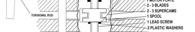
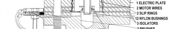
1 The IVOPROP operates on a COMPLETELY UNIQUE adjustable pitch system that allows for substantially less hardware and rotating mass than any other ground pitch adjustable prop. The unique pitch adjustment design operates on the principle of twisting the blades through the chrom-moly alloy steel torsional rod cast inside the blade. The outer end of the torsional rod is firmly anchored inside the outer blade section. The round torsional rod is capable of rotating inside the blade, except for the outer end. Both models utilize the same carbon / graphite fiber blades with stainless steel leading edges. The blades are capable of pitch change 3 to 17 degrees on the tips or inches of helix advancement from 18 to 52. The ability to change the pitch in flight is as significant for the airplane pilot as for the driver of a car to shift gears in the transmission. This results in substantial savings in fuel, engine wear and noise. Pilot controls the pitch through the toggle switch mounted in the cockpit. Pressing the toggle switch one way sends electric current trough the graphite brushes to the slip rings and finally to the electric motor. Depressing the toggle switch the other way reverses the polarity of current and the rotation of electric motor. The pitch changes operation is similar to the power windows in an automobile. As long as you hold the switch in one direction- the pitch changes in that direction and you observe the result on your RPM meter. Torque from the electric motor is multiplied in a two-stage planetary gear drive, which turns the lead screw. Lead screw is supported by a thrust bearing and converts it s rotary motion into axial movement of the spool. The spool is linked to the supercams, which turn the torsional rods. Torsional rods transmit the movement from the center of the prop to the outside section of the blade. This causes the blade to twist therefore changing the pitch in the same manner as the ground adjustable pitch system. Total time required for full range of adjustment is about 5 seconds. Movement of the spool can be restricted each way by inserting washers on the lead screw. This limits maximum and minimum pitch and prevents engine over-revving. Mounts directly to any rotax gearbox, Can be adapted to other engines. Older models Ivoprop ground adjustable props can be convert to In-Flight Adjustable System by means of retrofit kit. In-Flight adjustable hub comes assembled with instructions on how to use it. Total weight of 3-blades 72 diameter In-Flight Adjustable IVOPROP including wire harness, spinner, control switch, mounting hardware, and the circuit breaker is 10lbs. 1UE
2
3 Assembly Insert the mounting bolt with the washer through the motor plate in one of the bolt holes closest to the two motor wires. Insert one blade on the mounting bolt. Flat airfoil side towards the electric motor for pusher. Curved airfoil side toward electric motor for tractor. Rotate the blade so that the super cam goes into the groove in the spool. Insert second bolt through the motor plate and blade. Insert electrical plate (the one without nylon bushings) on the bolts. Insert small isolator. Insert slip ring on the bolts. Do not push out the nylon bushings. Bend one motor wire in right angle radially outward on the slip ring. Insert second small isolator. Bend second motor wire the same way like the first one on the isolator. Insert second slip ring. Insert large isolator. Bolt prop loosely on the flange. Insert remaining blade (s) between plates and torque mounting bolts to 200 inch X Lbs. Rotax reduction B : replace one of the 8mm nuts on the gearbox closest to the prop axis with a coupling nut (torque 150inch X Lbs.) Screw the stud into the coupling nut deep enough to clear the blades, and lock it with jam nut. Rotax reduction C : replace 6mm bolt on the gearbox with stud and countertorque one of the jam nuts against the gearbox 100inch. X Lbs. Other than Rotax : Mount the stud somehow next to the flange so that brushes will contact slip rings Screw the jam nut on the stud, insert the brush housing and screw the last jam nut on the stud. Position and torque the jam nuts against brush housing so that brush on the blade side is in contact with brush plate right next to the isolator. That way there is a maximum clearance between brush housing and the blades. Install switch and circuit breaker in the cockpit in a place where you can easy reach but not accidentally activate. Attach 3/16 connectors to the brush housing running the wire under the stud. Attach battery connectors to the battery. Circuit breaker wire belongs to the positive pole. Write next to the switch direction of the pitch change. By interchanging brush connectors you can change the direction of the pitch change. Example: Pitch up RPM down Cruise Pitch down RPM up Climb * Caution : Brushes are brittle. Do not brake them. 3UE
4 Setting Your Own Pitch Limits The pitch change operation in flight can be greatly simplified by restricting movement of the spool therefore limiting the pitch change from your best climb pitch to your best cruise pitch. Land with the prop in your best climb pitch. Take prop off the flange. Do not take the mounting bolts out of the prop. Measure (with a caliper) the distance from the spool and the end of the lead screw and write it down. Mount the prop back on the flange. Go flying and find your almost best cruise pitch. Remember almost stands for the pitch which will still give you a little bit of climb. Land the prop in your almost best cruise pitch. Take the prop of the flange and measure the distance between the spool and the end of the lead screw and write down. Mount the prop back on the flange and bring it to neutral (you can hear it no load on the electric motor.) Take prop a part. Insert limit washers on the lead screw so that spool can not travel beyond your measurements. Do not forget to insert plastic washers on each side of the spool. Failure to do so will immediately lead to the destruction of the gears in the planetary drive. Note: the thickness of the plastic washer under load is about ½ of its original thickness. How To Fly With It. Do the first flight in still air. Run the prop W.O.T. on the ground and adjust pitch of few hundred R..P.M. bellow your maximum HP R.P.M. (W.O.P. means wide open throttle.) Climb W.O.T. and adjust the pitch to maximum climb rate. (Do not exceed maximum allowable R.P.M. for your power plant.) Remember your R.P.M. at your best climb pitch. After reaching cruising altitude hold W.O.T. and start increasing pitch by short impulses until your climb rate is about 200ft/min. Remember your W.O.T. R.P.M. at this your almost best cruise pitch. Throttle back until your R.P.M. start dropping or until your climb is zero. Before landing go for a moment into W.O.T. and start decreasing the pitch by short pulses until you reach your best climb R.P.M. which you remember from the take-off. Do not change the pitch after landing. Run the prop W.O.T. on the ground and remember your best climb R.P.M. which you remember from the take off. Before next take-off run prop W.O.T. and read your best climb ground R.P.M. to make sure that your pitch is in climb setting. Next time you want to cruise even in a turbulent air just use your almost best cruise R.P.M. which you remember from your last flight in order to put prop in your almost best cruise pitch. 4UE
5 Important: Assume that in-flight pitch adjustment can quit on you any time in which case the pitch stays where it is. Therefore do not pitch prop up for cruise more than you need to slightly climb. So you can bring your plane back where you came from. Do not use pitch adjustment more than you need and always allow some time for electrical components to cool down between cycles. Do not run the prop without the circuit breaker, which is supplied with it. If you hold the switch for few seconds after reaching the pitch limit therefore stalling the motor the circuit breaker pops out and you have to wait several seconds to reset it. The system will not run safely on regulated DC current from regular therefore you need a battery. Before disassembling the prop always bring the pitch to the neutral. Never engage pitch adjustment only on one blade or on two blades spaced 120 degrees. Do not remove carbon deposit from brushes on slip rings. Do not rely on spring, which returns the switch lever to the neutral position. If you can t change the pitch in-flight try it in idle R.P.M. or try to move the switch lever back and forth. Even if you fly without setting your pitch limits you still need one limit washer the castle nut and the plastic washer. Do not shorten the 12 wires or circuit breaker will pop out sooner. Keep the grease away from plastic and limit washers. Brushes wear much faster when wet. Therefore if you really have to fly in a rain pitch the prop for climb, loosen the jam nut, which is against coupling nut, turn brush housing away from brush plates and re-torque the jam nut. Make sure that there is no electric continuity between brush and plates and the engine frameotherwise you could destroy your regulator-rectifier when changing the pitch while engine is running. After you are done with setting the limits and the final installation seal the gaps between the blades with silicon and install the spinner to keep the water and dust from getting into the mechanism. Tie down or put the tape over the brush connectors so they will not come loose in flight. Apply blue loctite on the spinner bolt and bolt and torque to 35 inch X Lbs. otherwise your spinner will fall off. If you wish to secure mounting bolts- use 8mm nylon lock nuts (not supplied) on the other side of the flange. Use only the hardware supplied with the prop, never drill or modify the bolt holes in the blade (s). Maintain the 200-inch X Lbs. torque on the bolts. Make sure that there is at least 5 of clearance between the blade tips and trailing edge of the wing, radiator rudder, or whatever, because the blades are design to flex back and forth more than wooden blades. Do not slide your fingers along the trailing or leading edge of the blade, fibers may pierce your skin. If you wish to increase top speed or decrease cruise R.P.M., switch to a 2-blade 2 prop or cut the 3-blade 3 prop to a smaller diameter using a hack saw, as long as you cut the t same length piece from each blade, the prop will remain in balance. Do not cut the prop to less than 48 diameter. When switching from 3-blade 3 to a 2-blade 2 configuration, increase the pitch about 4 degrees. Rotax engines develop maximum horsepower around 6500 RPM so pitch the prop accordingly. If you are going to use other than skull cap type spinner make sure that there is at least ¼ clearance between blades and cut-outs in the spinner. If your aircraft holds u.s. experimental airworthiness certificate te you are supposed to contact the F.A.A. FSDO before flying the aircraft. When notified, the F.A.A. inspector can determine if procedure was major change (as defined per far and listed in appendix a to part 43) and if any additional inspections or operating limitations are needed prior the flight. 5UE
NEUFORM 3-Blade-Variable Pitch Propeller R2 Series. Assembly and Maintenance Manual
 NEUFORM 3-Blade-Variable Pitch Propeller R2 Series for Rotax 912, 912S and 914 Manual control by hand lever (H) or electric constant speed control (ECS) Date: 28 April 2010 Your NEUFORM-Distributor: Table
WHIRLWIND. Owner s Manual 400C-M14 Series (Rev ) Model: 400C-M14 Serial Number: Manufacture Date: A V I A T I O N WHIRL WIND AVIATION
 Model: 400C-M14 Serial Number: Manufacture Date: A V I A T I O N WHIRL WIND AVIATION") WHIRLWIND A V I A T I O N M a nufacturer of Composite Constant Speed P r o pellers Model: 400C-M14 Serial Number: Manufacture Date: Owner s Manual 400C-M14 Series (Rev 2014-2) WHIRL WIND AVIATION 1419
WHIRLWIND A V I A T I O N M a nufacturer of Composite Constant Speed P r o pellers Model: 400C-M14 Serial Number: Manufacture Date: Owner s Manual 400C-M14 Series (Rev 2014-2) WHIRL WIND AVIATION 1419
Step #1 From your spool of 18 gauge primary wire, cut between 11 and 21 three inch strips of wire. You will only need 11 for the ROV, but it is good t
 How to make a ROV! Step #1 From your spool of 18 gauge primary wire, cut between 11 and 21 three inch strips of wire. You will only need 11 for the ROV, but it is good to have extras. Using the wire cutter,
INDEX. Preflight Inspection Pages 2-4. Start Up.. Page 5. Take Off. Page 6. Approach to Landing. Pages 7-8. Emergency Procedures..
 INDEX Preflight Inspection Pages 2-4 Start Up.. Page 5 Take Off. Page 6 Approach to Landing. Pages 7-8 Emergency Procedures.. Page 9 Engine Failure Pages 10-13 Propeller Governor Failure Page 14 Fire.
Section 13. Tail Rotor Drive. RotorWay International A600 TALON Construction Manual. Section 13. Page A
 RotorWay International Page A Tail Rotor Drive Procedures covered in this section: Install driveshafts and gearboxes; install drive belt and tensioner; fabricate and install tail rotor pitch actuator arms;
WHIRLWIND. Owner s Manual Series (Rev ) Serial Number: Manufacture Date: A V I A T I O N Model: WHIRL WIND AVIATION
 Serial Number: Manufacture Date: A V I A T I O N Model: WHIRL WIND AVIATION") WHIRLWIND A V I A T I O N Model: 100-4 Serial Number: 100-4- Manufacture Date: M a nufacturer of Composite Constant Speed P r o pellers Owner s Manual 100-4 Series (Rev 2014-2) WHIRL WIND AVIATION 1419
WHIRLWIND A V I A T I O N Model: 100-4 Serial Number: 100-4- Manufacture Date: M a nufacturer of Composite Constant Speed P r o pellers Owner s Manual 100-4 Series (Rev 2014-2) WHIRL WIND AVIATION 1419
WHIRLWIND. Owner s Manual 200RV Series (Rev ) Model: 200RV Serial Number: 200RV- Manufacture Date: A V I A T I O N WHIRL WIND AVIATION
 Model: 200RV Serial Number: 200RV- Manufacture Date: A V I A T I O N WHIRL WIND AVIATION") WHIRLWIND A V I A T I O N M a nufacturer of Composite Constant Speed P r o pellers Model: 200RV Serial Number: 200RV- Manufacture Date: Owner s Manual 200RV Series (Rev 2014-2) WHIRL WIND AVIATION 1419
WHIRLWIND A V I A T I O N M a nufacturer of Composite Constant Speed P r o pellers Model: 200RV Serial Number: 200RV- Manufacture Date: Owner s Manual 200RV Series (Rev 2014-2) WHIRL WIND AVIATION 1419
WHIRLWIND. Owner s Manual 151H Series (Rev ) Model: 151H Serial Number: Manufacture Date: A V I A T I O N WHIRL WIND AVIATION
 Model: 151H Serial Number: Manufacture Date: A V I A T I O N WHIRL WIND AVIATION") WHIRLWIND A V I A T I O N M a nufacturer of Composite Constant Speed P r o pellers Model: 151H Serial Number: Manufacture Date: Owner s Manual 151H Series (Rev 2014-2) WHIRL WIND AVIATION 1419 STATE ROUTE
WHIRLWIND A V I A T I O N M a nufacturer of Composite Constant Speed P r o pellers Model: 151H Serial Number: Manufacture Date: Owner s Manual 151H Series (Rev 2014-2) WHIRL WIND AVIATION 1419 STATE ROUTE
Here is the gap seal I used for the flaps, genuine hardware store quality. Note cross sectional shape visible on the right end.
 HOMEBUILT AIRCRAFT DRAG REDUCTION - Case Study with a Lancair IV Part 3 Copyright - Fred Moreno - January 2009 Rev. 1 Portions may be reproduced for private, individual use 3- REDUCED AIRFRAME DRAG FOR
Next, chase the threads in the lower A-arm mounts with the 5/8-18 tap and blowout any remaining particles.
 Next, chase the threads in the lower A-arm mounts with the 5/8-18 tap and blowout any remaining particles. Now, apply some anti-seize to the threads of the pivot stud. Also put anti-seize inside the bore
LINDGREN-PITMAN General Maintenance of Lindgren-Pitman Hydraulic Systems & Equipment
 LINDGREN-PITMAN General Maintenance of Lindgren-Pitman Hydraulic Systems & Equipment Page 1 Lindgren Pitman hydraulic driven equipment is designed to give long reliable service with a minimum of repairs
Installation Instructions
 Preparing your vehicle to install your brake system upgrade 1. Rack the vehicle. 2. If you don t have a rack, then you must take extra safety precautions. 3. Choose a firmly packed and level ground to
WHIRLWIND. Owner s Manual 375RV Series (Rev ) Model: 375RV Serial Number: 375RV- Manufacture Date: A V I A T I O N WHIRL WIND AVIATION
 Model: 375RV Serial Number: 375RV- Manufacture Date: A V I A T I O N WHIRL WIND AVIATION") WHIRLWIND A V I A T I O N M a nufacturer of Composite Constant Speed P r o pellers Model: 375RV Serial Number: 375RV- Manufacture Date: Owner s Manual 375RV Series (Rev 2014-3) WHIRL WIND AVIATION 1419
WHIRLWIND A V I A T I O N M a nufacturer of Composite Constant Speed P r o pellers Model: 375RV Serial Number: 375RV- Manufacture Date: Owner s Manual 375RV Series (Rev 2014-3) WHIRL WIND AVIATION 1419
WHIRLWIND. Owner s Manual 200C / 400C Series (Rev ) Model: Serial Number: Manufacture Date: A V I A T I O N WHIRL WIND AVIATION
 Model: Serial Number: Manufacture Date: A V I A T I O N WHIRL WIND AVIATION") WHIRLWIND A V I A T I O N M a nufacturer of Composite Constant Speed P r o pellers Model: Serial Number: Manufacture Date: Owner s Manual 200C / 400C Series (Rev 2014-2) WHIRL WIND AVIATION 1419 STATE
WHIRLWIND A V I A T I O N M a nufacturer of Composite Constant Speed P r o pellers Model: Serial Number: Manufacture Date: Owner s Manual 200C / 400C Series (Rev 2014-2) WHIRL WIND AVIATION 1419 STATE
Magnuson Intercooler Relocation
 Magnuson Intercooler Relocation Please read these instructions all the way through before beginning the installation. Doing so will definitely save you some rework. Although this installation can be accomplished
H-King R/C scale model series. instruction manual
 H-King R/C scale model series instruction manual 1. Please read this manual carefully and follow the instructions of the manual before you use this products. SAFETY INSTRUCTIONS 2. Our airplane is not
Performance means how fast will it go? How fast will it climb? How quickly it will take-off and land? How far it will go?
 Performance Concepts Speaker: Randall L. Brookhiser Performance means how fast will it go? How fast will it climb? How quickly it will take-off and land? How far it will go? Let s start with the phase
WHIRLWIND. Owner s Manual 400 Rocket Series (Rev ) Model: 400 Rocket Serial Number: Manufacture Date: A V I A T I O N WHIRL WIND AVIATION
 Model: 400 Rocket Serial Number: Manufacture Date: A V I A T I O N WHIRL WIND AVIATION") WHIRLWIND A V I A T I O N M a nufacturer of Composite Constant Speed P r o pellers Model: 400 Rocket Serial Number: Manufacture Date: Owner s Manual 400 Rocket Series (Rev 2014-2) WHIRL WIND AVIATION 1419
WHIRLWIND A V I A T I O N M a nufacturer of Composite Constant Speed P r o pellers Model: 400 Rocket Serial Number: Manufacture Date: Owner s Manual 400 Rocket Series (Rev 2014-2) WHIRL WIND AVIATION 1419
INSTALLING THE NEUTRAL SAFETY SWITCH WIRES
 Installation Instructions Magnum Grip Pro Bandit Shifter Part Number 81045 & 81046 2004, 2003 by B&M Racing and Performance Products (Visit www.bmracing.com for additional products and product information)
LINDGREN-PITMAN General Maintenance of Lindgren-Pitman Hydraulic Systems & Equipment
 LINDGREN-PITMAN General Maintenance of Lindgren-Pitman Hydraulic Systems & Equipment Page 1 Lindgren-Pitman hydraulic driven equipment is designed to give long reliable service with a minimum of repairs
Four Wheel Drive Kit Groundsmaster 580D
 Four Wheel Drive Kit Groundsmaster 580D FORM NO. 957 Rev B Model No. 0599 00 thru 99999 INSTALLATION INSTRUCTIONS POTENTIAL HAZARD Traction Unit rolls over. WHAT CAN HAPPEN Bodily injury could occur. 4
Table of Contents. Tail Wheel Assembly Installation.. page 01. Stabilizer Installation.. page 02. Fin Installation.. page 03
 Table of Contents Tail Wheel Assembly Installation.. page 01 Stabilizer Installation.. page 02 Fin Installation.. page 03 Elevator and Rudder Hinge Installation.. page 04 Rudder Controls.. page 05 Elevator
Installation Instructions Pro Bandit Shifter Fits: GM Powerglide Automatic Transmissions
 Installation Instructions Pro Bandit Shifter Fits: 1962-1973 GM Powerglide Automatic Transmissions Part # 80793 WORK SAFELY! For maximum safety, perform this installation on a clean, level surface and
COLD AIR INTAKE INSTALLATION INSTRUCTIONS. # D Fits: i (4.8L)
") COLD AIR INTAKE INSTALLATION INSTRUCTIONS # D760-0013 Fits: 2006-10 650i (4.8L) PARTS LIST Air Box Assembly Left tube Center tube Right tube Support bracket AFM housing AFM/TB tube Hardware Kit Congratulations
COLD AIR INTAKE INSTALLATION INSTRUCTIONS # D760-0013 Fits: 2006-10 650i (4.8L) PARTS LIST Air Box Assembly Left tube Center tube Right tube Support bracket AFM housing AFM/TB tube Hardware Kit Congratulations
Installation Instructions Table of Contents
 Installation Instructions Table of Contents Pre- Installation of Garage Storage Lift 2 Layout the Garage Storage Lift 3 Installing the strut Channels 3 Install the Drive Assembly 5 Install the Drive Shaft
HURST COMP/PLUS SHIFTER 2015 Ford Mustang (Getrag MT82 six-speed manual transmission) Catalog # by Hurst Performance
 Catalog # by Hurst Performance") FORM 159 0205 07/15 HURST COMP/PLUS SHIFTER 2015 Ford Mustang (Getrag MT82 six-speed manual transmission) Catalog #391 0205 2015 by Hurst Performance Thank you for purchasing the Hurst Comp/Plus Shifter.
FORM 159 0205 07/15 HURST COMP/PLUS SHIFTER 2015 Ford Mustang (Getrag MT82 six-speed manual transmission) Catalog #391 0205 2015 by Hurst Performance Thank you for purchasing the Hurst Comp/Plus Shifter.
This manual covers all color schemes Although it only shows one color scheme, the aircraft are the same This manual is for reference to the actual
 This manual covers all color schemes Although it only shows one color scheme, the aircraft are the same This manual is for reference to the actual product at the time it was written. We can't speak for
COLD AIR INTAKE INSTALLATION INSTRUCTIONS. # D Fits: i (4.8L)
") COLD AIR INTAKE INSTALLATION INSTRUCTIONS # D760-0012 Fits: 2006-10 550i (4.8L) PARTS LIST Air Box Assembly Left tube Center tube Right tube Outer Tube AFM housing AFM/TB tube Hardware Kit Congratulations
COLD AIR INTAKE INSTALLATION INSTRUCTIONS # D760-0012 Fits: 2006-10 550i (4.8L) PARTS LIST Air Box Assembly Left tube Center tube Right tube Outer Tube AFM housing AFM/TB tube Hardware Kit Congratulations
However, for pattern flying the advantages that a Contra-Rotating System can offer are considerable. These advantages are as follows:
 1 Contra Rotating Propeller Drive System User Guide Introduction Congratulations! You have just purchased a Contra-Rotating Propeller Drive System, which has been specially designed for use in f3a pattern
Clutches for Automobiles and Light Trucks
 Clutches for Automobiles and Light Trucks What does the Clutch do? Connects the engine torque to transmission when ENGAGED Unhooks engine from transmission when DISENGAGED Where is the driver s foot when
How to use the Multirotor Motor Performance Data Charts
 How to use the Multirotor Motor Performance Data Charts Here at Innov8tive Designs, we spend a lot of time testing all of the motors that we sell, and collect a large amount of data with a variety of propellers.
Retrofit Steering Column
 Retrofit Steering Column INSTALLATION INSTRUCTIONS for 1965-66 Ford Trucks FOR PART NUMBER S: 1170825010, 1170825020, 1170825051 www.ididit.com 610 S. Maumee St., Tecumseh, MI 49286 PH: (517) 424-0577
ROYAL CANADIAN AIR CADETS PROFICIENCY LEVEL FOUR INSTRUCTIONAL GUIDE SECTION 2 EO M DESCRIBE PROPELLER SYSTEMS PREPARATION
 ROYAL CANADIAN AIR CADETS PROFICIENCY LEVEL FOUR INSTRUCTIONAL GUIDE SECTION 2 EO M432.02 DESCRIBE PROPELLER SYSTEMS Total Time: 30 min PREPARATION PRE-LESSON INSTRUCTIONS Resources needed for the delivery
PIPER CUB J3-65 N68952 PRE-FLIGHT CHECKLIST COCKPIT
 PIPER CUB J3-65 N68952 PRE-FLIGHT CHECKLIST COCKPIT Check airworthiness certificate, registration, weight & balance documentation Battery - CONNECTED Plug in headsets or secure as required Fuel ON Magnetos
Slave Cylinder Weep Hole Drilling Procedure
 Slave Cylinder Weep Hole Drilling Procedure Tools Required: T20 Torx Driver T25 Torx Driver T25 Torx Bit with ¼ Ratchet Wrench 4mm Hex Key (Allen wrench) 5mm Hex Key 6mm Hex Key 8mm Hex Key 12mm Hex Key
AIR TRACTOR, INC. OLNEY, TEXAS
 TABLE OF CONTENTS LOG OF REVISIONS... 2 DESCRIPTION... 4 SECTION 1 LIMITATIONS... 5 SECTION 2 NORMAL PROCEDURES... 8 SECTION 3 EMERGENCY PROCEDURES... 8 SECTION 4 MANUFACTURER'S SECTION - PERFORMANCE...
Applicability Aircraft serial Nos. affected: The maintenance manual to be referenced is this stated or subsequent issue.
 Title: IVO-prop gearbox overhaul AG-SB-2017-05-B-EN Aircraft type & model: Any AutoGyro type fitted with IVOprop DL3-68 VP-propeller Applicability Aircraft serial Nos. affected: Any AutoGyro type fitted
ITEMS INCLUDED. 2.4GHz Controller
 READ THESE INSTRUCTIONS BEFORE FLYING! ITEMS INCLUDED.4GHz Controller Flight Battery Charger SKY Cruiser LiPo Flight Battery AA Batteries AC Power Supply WARNINGS FOR YOUR SAFETY PLEASE READ AND UNDERSTAND
PIPER CUB J3-65 N68952 PRE-FLIGHT CHECKLIST
 PRE-FLIGHT CHECKLIST COCKPIT Check airworthiness certificate, registration, weight & balance documentation Battery - CONNECTED Plug in headsets or secure as required Fuel ON Primer CLOSED & LOCKED Carb
Tribal Knowledge, converting an Enstrom Piston helicopter from Lamiflex bearings to TT straps
 Tribal Knowledge, converting an Enstrom Piston helicopter from Lamiflex bearings to TT straps The Airwolf kit comes with all parts necessary for assembly and is pre-packaged in shock proof packaging. 1
Cessna 172RG WARNING. Maximum Demonstrated Crosswind. Takeoff or landing..15 KTS
 Cessna 172RG INTRODUCTION: This aircraft checklist contains information from the original manufacturer s Pilot Information Manual. Normal procedures associated with optional systems can be found in Section
Retrofit Steering Column
 Retrofit Steering Column INSTALLATION INSTRUCTIONS for 1965 Ford Falcon FOR PART NUMBER S: 1170906010, 1170906020, 1170906051, 1130906010, 1130906020, 1130906051 S INCE 1986 www.ididitinc.com 610 S. Maumee
Retro it Steering Column
 Retro it Steering Column INSTALLATION INSTRUCTIONS for 1976-86 CJ5 & CJ7 FOR PART NUMBER S: 1520800010, 1520800020, 1520800051, 1526800010, 1526800020, 1526800051 S I NCE 1986 Instruction # 8000000010
INSTALLATION INSTRUCTION Rev A
 INSTALLATION INSTRUCTION 88587 Rev A FOR RANCHO SUSPENSION SYSTEM RS6587B: 2009 DODGE RAM 1500 READ ALL INSTRUCTIONS THOROUGHLY FROM START TO FINISH BEFORE BEGINNING INSTALLATION IMPORTANT NOTES! WARNING:
PHOENIX Features of the Phoenix-25 : 2.3 Connecting the Motor. 2.4 Reversing Rotation. 2.5 Connecting the Receiver
 Warning! High power motor systems can be very dangerous! High currents can heat wires and batteries, causing fires and burning skin. Follow the wiring directions carefully! Model aircraft equipped with
INSTALLATION INSTRUCTION 88581
 INSTALLATION INSTRUCTION 88581 FOR RANCHO SUSPENSION SYSTEM RS6581B: DODGE RAM READ ALL INSTRUCTIONS THOROUGHLY FROM START TO FINISH BEFORE BEGINNING INSTALLATION Rev C IMPORTANT NOTES! WARNING: This suspension
F3D-30 ARF ASSEMBLY MANUAL
 F3D-30 ARF ASSEMBLY MANUAL This Manuel is the sole property of Kangke Industrial USA, Inc. Reproducing any part without the consent of Kangke Industrial USA, Inc. is a lawful violation. Kangke Industrial
Maintenance Instruction 23.1
 Subject: Replacement of engine GROB 2500 E1/D1 by engine LIMBACH L 2400 EB1.AA Affected Aircraft: Motor glider GROB G 109 (B) Aircraft: Type G 109 (B) Registration Propeller: Type MTV-1-A/L160-03 Serial
Installation Operation Maintenance. LSSN Butterfly Valve AGA Approved 50MM - 150MM. QAD#IM6055.REVA
 LSSN Butterfly Valve Installation Operation Maintenance Licence Number: 5326 www.challengervalves.com.au 1 Index 1. INTRODUCTION 1.1 Design Features 3 1.2 Flange and Pipe Compatibility 4 1.3 Operating
INTRODUCTION TO TRANSMISSION SYSTEM :-
 INTRODUCTION TO TRANSMISSION SYSTEM :- TYPES OF TRANSMISSION SYSTEM CLUTCH GEAR BOX PROPEELER SHAFT UNIVERSAL JOINTS Final drive and differential REAR AXLE Definition Of Transmission System :- The mechanism
WHIRLWIND. Owner s Manual 200G-CS & 210 (Rev ) Model: Serial Number: Manufacture Date: A V I A T I O N WHIRL WIND AVIATION
 Model: Serial Number: Manufacture Date: A V I A T I O N WHIRL WIND AVIATION") WHIRLWIND A V I A T I O N M a nufacturer of Composite Constant Speed P r o pellers Model: Serial Number: Manufacture Date: Owner s Manual 200G-CS & 210 (Rev 2014-2) WHIRL WIND AVIATION 1419 STATE ROUTE
WHIRLWIND A V I A T I O N M a nufacturer of Composite Constant Speed P r o pellers Model: Serial Number: Manufacture Date: Owner s Manual 200G-CS & 210 (Rev 2014-2) WHIRL WIND AVIATION 1419 STATE ROUTE
PHOENIX Features of the Phoenix-10 : 2.3 Connecting the Motor. 2.4 Reversing Rotation. 2.5 Connecting the Receiver
 Warning! High power motor systems can be very dangerous! High currents can heat wires and batteries, causing fires and burning skin. Follow the wiring directions carefully! Model aircraft equipped with
Safety - Installation and Operation:
 4x4 or 4x2 Instructions EZGO Electric Cars Thank you for purchasing your 4x4 or 4x2 conversion kit. Safety at all times whether during installation or operation is utmost importance. Before After!!!!!!!!!!!!!!
FLIGHT CONTROLS SYSTEM
 FLIGHT CONTROLS SYSTEM DESCRIPTION Primary flight control of the aircraft is provided by aileron, elevator and rudder control surfaces. The elevator and rudder control surfaces are mechanically operated.
Seabee Annual Inspection Procedures
 Procedures Due to the wide variety of Seabee s flying out there, these procedures should be modified to fit YOUR Seabee. Make sure that all AD s are complied with as well as any required Service Bulletins
2006 Honda Civic SI Supercharger Kit Installation Instruction Kit #
 2006 Honda Civic SI Supercharger Kit Installation Instruction Kit #350-091 3239 MONIER CIRCLE, STE.5 RANCHO CORDOVA, CA 95742 916.635.4550 FAX 916.635.4632 www.ct-engineering.com INS-157 VERSION: 3.25.2009
DIAGNOSIS AND TESTING
 DIAGNOSIS AND TESTING SUSPENSION AND STEERING SYSTEM 2007 SUSPENSION Suspension - Nitro CONDITION POSSIBLE CAUSES CORRECTION FRONT END NOISE 1. Loose or worn wheel bearings. 1. Replace wheel bearings.
DUCHESS BE-76 AND COMMERCIAL MULTI ADD-ON ORAL REVIEW FOR CHECKRIDE
 DUCHESS BE-76 AND COMMERCIAL MULTI ADD-ON ORAL REVIEW FOR CHECKRIDE The Critical Engine The critical engine is the engine whose failure would most adversely affect the airplane s performance or handling
Constant Speed Propeller Control
 Constant Speed Propeller Control Overview: An aircraft engine is designed to operate over a relatively small range of revolutions per minute (RPM). This is because propellers are limited by rotational
FRONT AXLE AND SUSPENSION FA 1
 FRONT AXLE AND SUSPENSION FA1 FRONT AXLE AND SUSPENSION FA2 FRONT AXLE AND SUSPENSION Troubleshooting TROUBLESHOOTING Problem Possible cause Remedy Page Wanders/pulls Tires worn or improperly inflated
Safety First. Please remember to always use SAFE shop practices when performing all service procedures.
 Safety First Please remember to always use SAFE shop practices when performing all service procedures. 2006 Update Manual January 2006 Country Clipper 2006 Update Manual Index Joystick Kill Switch Oil
Transmission Overhaul Procedures-Bench Service
 How to Assemble the Lower Reverse Idler Gear Assembly Special Instructions In 1996 Eaton changed the reverse idler system design. In the nut design, the reverse idler bearing was lubricated through a hole
RD St N West Palm Beach, FL (478)
") 14842 93 RD St N West Palm Beach, FL 33412 1-(478) 247 7275 www.ch-ignitions.com Saito 450 R CH Ignition Glow CDI & Gasoline Conversions Kit Install Instructions By converting your engine you may void
14842 93 RD St N West Palm Beach, FL 33412 1-(478) 247 7275 www.ch-ignitions.com Saito 450 R CH Ignition Glow CDI & Gasoline Conversions Kit Install Instructions By converting your engine you may void
Tech Note Truck 14 & 15.5 Twin Plate Cast Iron Type Installation Guidelines
 1. (14 & 15.5 ) Check condition of the flywheel. Grind to resurface or replace flywheel. Surface MUST BE machined or premature clutch failure can occur. Flywheel depth must be 2.938 (74.62mm) for 14 (350mm)
Instructions for changing bearings on all B&C Technologies SP and HP models
 Instructions for changing bearings on all B&C Technologies SP and HP models Tools and material required: 30 mm socket Socket handle with extension or air impact wrench Regular Screwdriver Phillips head
PHOENIX ENIX Features of the Phoenix-60 : 2.3 Connecting the Motor. 2.4 Reversing Rotation. 2.5 Connecting the Receiver
 PHOENIX ENIX-60 Warning! High power motor systems can be very dangerous! High currents can heat wires and batteries, causing fires and burning skin. Follow the wiring directions carefully! Model aircraft
CROWERGLIDE AUTOMATIC CLUTCH Instruction Manual
 CROWERGLIDE AUTOMATIC CLUTCH Instruction Manual Crower Cams & Equipment Co., Inc 6180 Business Center Court San Diego, CA. 92154 Phone: 619.661.6477 ext. 148 Fax: 619.690.7846 www.crower.com TABLE OF CONTENTS
INSTALLATION & OWNER S MANUAL
 Rev. E p. of 3 INSTALLATION & OWNER S MANUAL V446 Front Cab Kit and V446 Rear Cab Kit for RTV 40 INSTALLATION & OWNER S MANUAL The contents of this envelope are the property of the owner. Be sure to leave
CIVIL AVIATION AUTHORITY SAFETY REGULATION GROUP MICROLIGHT TYPE APPROVAL DATA SHEET (TADS) NO: BM 55 ISSUE: 6
 NO: BM 55 ISSUE: 6") TYPE: Shadow Series D & DD (1) MANUFACTURER CFM Aircraft Ltd (ceased trading) BMAA is responsible for continued airworthiness (2) UK IMPORTER None (3) CERTIFICATION BCAR Section S (First example Issue
TYPE: Shadow Series D & DD (1) MANUFACTURER CFM Aircraft Ltd (ceased trading) BMAA is responsible for continued airworthiness (2) UK IMPORTER None (3) CERTIFICATION BCAR Section S (First example Issue
INSTALLATION INSTRUCTIONS DODGE DAKOTA 2 KIT # 682 (2WD), 692 (4WD) 3 KIT # 683 (2WD), 693 (4WD)
, 692 (4WD) 3 KIT # 683 (2WD), 693 (4WD)") INSTALLATION INSTRUCTIONS 1997-1999 DODGE DAKOTA 2 KIT # 682 (2WD), 692 (4WD) 3 KIT # 683 (2WD), 693 (4WD) Installation of a Performance Accessories body lift kit will change the vehicle s center of gravity
INSTALLATION INSTRUCTIONS 1997-1999 DODGE DAKOTA 2 KIT # 682 (2WD), 692 (4WD) 3 KIT # 683 (2WD), 693 (4WD) Installation of a Performance Accessories body lift kit will change the vehicle s center of gravity
Shadow Series D & DD
 Shadow Series D & DD 1 MANUFACTURER CFM Aircraft Ltd (ceased trading) BMAA is responsible for continued airworthiness 2 UK IMPORTER None 3 CERTIFICATION BCAR Section S (First example Issue 1 dated April
C I R R U S PROPELLER GENERAL
 PROPELLER 1. GENERAL The airplane employs a 3 blade, constant speed, non-feathering propeller. The blades (composite or aluminum) are mounted in an aluminum hub which contains the pitch changing mechanism
Synchronizing the 912 s Bing Carburetor Part 2
 . POWER ON. Phillip Lockwood Reaching Smooth Idle Synchronizing the 912 s Bing Carburetor Part 2 In April we discussed why it s important to synchronize the Rotax 912 s dual carburetors and described how
DRIVE AXLE Volvo 960 DESCRIPTION & OPERATION AXLE IDENTIFICATION DRIVE AXLES Volvo Differentials & Axle Shafts
 DRIVE AXLE 1994 Volvo 960 1994 DRIVE AXLES Volvo Differentials & Axle Shafts 960 DESCRIPTION & OPERATION All 960 station wagon models use type 1041 rear axle assembly. All 960 4-door models use type 1045
INSTALLATION INSTRUCTION 89400
 INSTALLATION INSTRUCTION 89400 FOR RANCHO SUSPENSION SYSTEM RS66400B: 2012 RAM 1500 4WD. READ ALL INSTRUCTIONS THOROUGHLY FROM START TO FINISH BEFORE BEGINNING INSTALLATION Rev B IMPORTANT NOTES! WARNING:
I. Before starting installation
 5. Park the vehicle on a clean, dry, flat, level surface and block the tires so the vehicle cannot roll in either direction. A. Disconnect battery cables 1. Disconnect the negative cable first, then the
XIV.C. Flight Principles Engine Inoperative
 XIV.C. Flight Principles Engine Inoperative References: FAA-H-8083-3; POH/AFM Objectives The student should develop knowledge of the elements related to single engine operation. Key Elements Elements Schedule
STOP---READ THIS FIRST!
 STOP---READ THIS FIRST! **Read These Entire Instructions Before Starting Anything** 2003-2013 DODGE Ram 2500/3500, 8 LIFT KIT NOTE: * The factory wheels and tires WILL fit on the front of the vehicle once
Module 17, Propeller.
 Module 17, Propeller. 17.1. Fundamentals. Question Number. 1. High speed propellers are designed to. Option A. rotate at high RPM. Option B. operate at high forward speeds. Option C. operate at supersonic
COLD AIR INTAKE INSTALLATION INSTRUCTIONS
 COLD AIR INTAKE INSTALLATION INSTRUCTIONS # D760-0030 Fits: 2007-10 135i (E82, E88; with N54 engine) 2007-08 335i/xi (E90) 2007-10 335i (E92, E93; with N54 engine) Congratulations for being selective enough
40 EP Gee Bee Y Scale ARF V2 Instruction Manual Specs:
 40 EP Gee Bee Y Scale ARF V2 Instruction Manual Specs: Wing Span: 40" Overall length: 30" Wing area: 306 sq. in Ready to fly weight: 28~32 oz Motor/Engine: Electric: Uranus-28309 brushless outrunner motor,
INSTALLATION INSTRUCTION 88088
 INSTALLATION INSTRUCTION 88088 For Rancho Suspension Systems RS6588 & RS6589: FORD F-150 READ ALL INSTRUCTIONS THOROUGHLY FROM START TO FINISH BEFORE BEGINNING INSTALLATION Rev B IMPORTANT NOTES! WARNING:
Flaps System. 1. General
 CIRRUS AIRPLANE MAINTENANCE MANUAL Flaps System CHAPTER 27-50: FLAPS SYSTEM GENERAL 27-50: FLAPS SYSTEM 1. General This section describes that portion of the flight control system which controls the position
Special Note About The JDM High Performance Water Pump:
 Page 1 of 30 JDM Engineering, Inc. home Call Us! 732-780- 0770 back to Installation Instructions Electric Fan Upgrade Kit Electric Fan Wiring Diagram Thank you for your purchase of the JDM Engineering
Series 1000 and Cutout
 17.15.Remove the belt from the tractor. NOTE: There were a small number of tractors made using a CVT drive and a 2-speed (L-H-N-R) GT transaxle. The belt must pass over the center mounted gear selector
Statement. 1.Please read this manual carefully and follow the instruction of the manual before you use this products;
 1 / 11 CONTENTS Statement-------------------------------------------------------------------------------------------------------------------------------------------------2 Brief introduction----------------------------------------------------------------------------------------------------------------------------------------3
Geared Drives 200Z PSRU Zero Offset Gearbox with Centrifugal Clutch Assembly
 Instructions for Removing and replacing Gen X Gearbox with Geared Drives 200Z Prior to your gear box arriving: Using a strap or chain and an engine hoist to hold your engine up in the mount, remove your
Propeller Assembly. 1. General
 Propeller Assembly GENERAL 61-10: PROPELLER ASSEMBLY 1. General The propeller assembly consists of a hollow aluminum hub which supports the propeller blades and also houses the pitch changing mechanism.
Installation Instructions COMPETITION/PLUS SHIFTER Ford Mustang MT82 6-Speed Manual Transmission Catalog#
 Installation Instructions COMPETITION/PLUS SHIFTER 2015-2017 Ford Mustang MT82 6-Speed Manual Transmission Catalog# 3916037 Rev. 00 WORK SAFELY! For maximum safety, perform this installation on a clean,
Pilots Manual for Propeller H60A series
 Pilots Manual for Propeller H60A series Propeller type: Serial No.: Date of sale: Stamp, Signature: Index List of Revisions... 3 1 Description... 4 2 General specification of Helix-Propeller types... 5
1967 (Late) and 1968 CORVETTE TELESCOPING STEERING COLUMN DISASSEMBLY & REPAIR INSTRUCTIONS - PAPER #1
 and 1968 CORVETTE TELESCOPING STEERING COLUMN DISASSEMBLY & REPAIR INSTRUCTIONS - PAPER #1") Last Revision: 03SE2012 1967 (Late) and 1968 CORVETTE TELESCOPING STEERING COLUMN DISASSEMBLY & REPAIR INSTRUCTIONS - PAPER #1 Disassembly and Repair Instructions Addressed in this Paper Difficulty Page
Last Revision: 03SE2012 1967 (Late) and 1968 CORVETTE TELESCOPING STEERING COLUMN DISASSEMBLY & REPAIR INSTRUCTIONS - PAPER #1 Disassembly and Repair Instructions Addressed in this Paper Difficulty Page
Lanier R/C F-4 Phantom
 Lanier R/C.40-.46 F-4 Phantom Almost Ready to Fly WARNING! THIS IS NOT A TOY! THIS IS NOT A BEGINNERS AIRPLANE This R/C kit and the model you will build from it is not a toy! It is capable of serious bodily
67-70 Cougar Rack Kit Instructions # &
 67-70 Cougar Rack Kit Instructions # 8011950-01 & 8011940-01 Unisteer offers a limited warranty against all manufacturer defects of their kits and supplied parts. Unisteer will not honor any warranty on
INSTALLATION MANUAL AP60B INSTALLATION MANUAL
 INSTALLATION MANUAL 2. TOOLS REQUIRED The following is a list of tools required to properly install the cruise control. While this unit may be installed without some of the tools listed, it is recommended
PHOENIX HV Features of the Phoenix HV-45 : 2.3 Connecting the Motor. 2.4 Reversing Rotation. 2.5 Connecting the Receiver
 PHOENIX HV -45 1.0 Features of the Phoenix HV-45 : Extremely Low Resistance (.003 ohms) High rate adjustable switching (PWM) Up to 45 Amps continuous current Dual Opto-Coupled (No BEC) Up to 36 cells or
RHINO SUSPENSION SYSTEM INSTALLATION INSTRUCTIONS
 PARTS INCLUDED: 2 FRONT UPPER A-ARMS 2 FRONT LOWER A-ARMS 2 UNI-BALL JOINTS 2 UNI-BALL JOINT STUDS 2 UNI-BALL JOINT CAPS 2 RETAINING RINGS 1 FRONT SHOCK ASSEM. 2 DELRON STEERING STOPS 2 SHOCK MOUNT SPACERS
P/N 135A FAA Approved: 5/14/2007 Section 9 Initial Release Page 1 of 10
 FAA APPROVED AIRPLANE FLIGHT MANUAL SUPPLEMENT FOR MT PROPELLER INSTALLATION Serial No: Registration No: When the MT Propeller is installed on the Liberty Aerospace XL2, this supplement is applicable and
CIRRUS AIRPLANE MAINTENANCE MANUAL
 PROPELLER 1. GENERAL The airplane employs a 3 blade, constant speed, non-feathering propeller. The blades (composite or aluminum) are mounted in an aluminum hub which contains the pitch changing mechanism
CIVIL AVIATION AUTHORITY SAFETY REGULATION GROUP MICROLIGHT TYPE APPROVAL DATA SHEET (TADS) NO: BM 41 ISSUE: 7
 NO: BM 41 ISSUE: 7") TYPE: Shadow Series CD (1) MANUFACTURER CFM Aircraft Ltd (ceased trading) BMAA is responsible for continued airworthiness (2) UK IMPORTER None (3) CERTIFICATION BCAR Section S (First example Advanced Issue
TYPE: Shadow Series CD (1) MANUFACTURER CFM Aircraft Ltd (ceased trading) BMAA is responsible for continued airworthiness (2) UK IMPORTER None (3) CERTIFICATION BCAR Section S (First example Advanced Issue
I-PNP Central Controller
 Central Controller Instructions For All PNP Models August 29, 2016 Version 2.2 BVM 2016 I-PNP Central Controller FUNCTIONS: Retract Gear (B-1) Long Press Manual Button Landing Gear Failsafe (B-2).Short