Safety Factors When repairing Kia vehicles it is important to follow the following recommendations.
|
|
|
- Ilene Bruce
- 6 years ago
- Views:
Transcription
1 Module 1 Kia Body Repair Manuals All Kia Body Repair Manuals (BRM) include a good overview of the vehicle body structure along with generic general information and cautions for repairing Kia vehicles. Much of the same information is included in all manuals and applies to all current models in the Kia fleet. Modules 1 of this manual will cover the Kia generic body repair information covering all models included in those course. Module 2 will look at model specific information for each of the following vehicles:- Picanto (TA) Rio (UB) Soul l (PS) 2015 Cerato (YD) 2,4 & 5 door 2014 Pro-Ceed (JD) 2013 Optima (TF) 2014 Carens (RP) 2014 Sportage (SL) Sorento (UM12) Carnival (YD) Light truck K2900 (PU) General Information General Guide Lines and Precautions This vehicle is a completely new design. During its development, close attention has been given to safety, stability, weight and corrosion protection. Typical of unibody design, the vehicle is designed so that the front and rear compartments will absorb much of the collision energy so that the passengers are better protected. During collisions, these front and rear energy absorbing systems may be severely damaged. During repair, these damaged areas must be returned to their original strength and geometry. If this is not properly done, the vehicle will not provide the intended level of protection to its occupants in the event of another collision. The repairs described in this manual were performed on the vehicle's body shells. In some instances special fixtures were welded in place to support the structure. During the repair of an actual vehicle, the interior would be fully disassembled and standard jack screws or portable braces may be used for temporary support. During the repair of an accident involved vehicle, the vehicle must first be returned to pre-impact dimensions prior to beginning the sectioning repair procedures. The extent of damage that must be repaired should then be evaluated to determine the appropriate repair procedures. This manual provides locations and procedures where structural sectioning may be employed. It is the responsibility of the repair technician, based upon the extent of damage, to determine which location and procedure is suitable for the particular damaged vehicle. During the repair of a collision damaged automobile, it is impossible to fully duplicate the methods used in the factory during the vehicle manufacture. Therefore, auto body repair techniques have been developed to provide a repair that has strength properties equivalent to those of the original design and manufacture. Safety Factors When repairing Kia vehicles it is important to follow the following recommendations. 1. Disconnect the negative (-) battery cable before performing any work on the vehicle. 2. Protect yourself by wearing goggles, earplugs, respirators, gloves, safety shoes, caps, etc. when working on a vehicle. 3. Safely support the vehicle before any work is done. Block the front or rear wheels if the vehicle is not lifted off of the ground 4. When welding or performing other procedures that require the use of an open flame near the fuel tank, disconnect and remove the tank and fuel pipe, and cap the pipe to prevent fuel leakage 5. Ensure proper ventilation of your working area. Some paint and sealant can generate toxic gases when heated. Use an air chisel or saw to remove damaged panels instead of a gas torch. 6. Observe all local and national safety regulations when performing any work. 7. Cover interior with heat-resistant cover to ensure safety when welding. 8. Take care when using gas or cutting torches so as not to burn body sealer or interior. Extinguish immediately if they should catch fire. 1

2 SRS Air-Bag This vehicle is equipped with a Supplemental Restraint System AIR-BAG to provide the vehicle's driver and/or the front passenger with additional protection than that offered by the seat-belt system alone, in case of a frontal impact of sufficient severity. When handling airbag components (removal, installation or inspection, etc.), always follow the directions given in the repair manual for the relevant model to prevent the occurrence of accidents and airbag malfunction. 1. Work must be started after approximately 30 seconds or longer from the time the ignition switch is turned to the LOCK position and the negative (-) terminal cable is disconnected from the battery. (The airbag system is equipped with a back-up power source so that if work is started within 30 seconds of disconnecting the negative (-) terminal cable of the battery, the airbag may be deployed.) When the negative (-) terminal cable is disconnected from the battery, memory of the clock and audio systems will be cancelled. So before starting work, make a record of the contents memorized by the audio memory system. Then when work is finished, reset the audio system as before and adjust the clock. 2. When using electric welding, first disconnect the air-bag connectors under the steering column near the MULTI- FUNCTION SWITCH and the passenger's side crash pad before starting work. 3. Store the air-bag modules where the ambient temperature remains below 93 C (200F ), without high humidity and away from electrical noise. 4. WARNING/CAUTION labels are attached to the periphery of the air-bag components. Refer to the SHOP MANUAL. Note; detailed illustrations showing where airbag, sensors and components are shown for each model. This should be checked before removal of any interior trim panels. The following examples show illustrations for the Optima (TF) 2014 and the pressure sensor of the UM model. Welding All repairs in this manual require the use of a Metal-Inert Gas (MIG) welder, Gas (oxyacetylene) welding must not be used. Both high strength steel and mild steel can be welded using the MIG welder. The I-CAR recommendations for welding should be followed. The shielding gas should be 75% Argon and 25% CO2. The recommended welding wire size is 0.23" and the wire should satisfy the American Welding Society standard code AWSER70S-6. During the repair process, plug welds are used to duplicate original factory spot welds. All plug welds should be done with the MIG welder. An 8mm (5/16") hole is placed in the top (welding side) sheet metal. Then begin welding along the edges and the spiral towards the centre (see illustration). This is important so that weld penetration between the two metal pieces takes place along the circumference of the circle. Observe the following tips when welding. 1. Wear appropriate eye protection. 2. Carefully follow the manufacturer s operating instructions for the welding machine you are using. 2
3 3. Do not weld, smoke or allow open flames around volatile chemicals, cleaners or solvents or in any area where they have just been used. Measuring Dimensions before Welding When installing a new part, assemble it according to the body dimensions given in Section BD, and start welding after checking the gaps with nearby parts. Caution when Welding The number of welding points should be determined based on the criteria below: Caution when Spot Welding The tip of the spot welding machine should be maintained to a minimum of 3mm (0.1 in) because it greatly affects welding strength. When possible, spot welding should be done between the existing spot welded points. Before and after spot welding, weld a test piece (test pin) of the same material as the body panel, and check the welding strength. Electronic Parts Vehicles today include many electronic parts and components, and these are in general very susceptible to adverse effects caused by overcurrent, reverse current, electromagnetic waves, high temperature, high humidity impacts, etc. In particular such electronic components can be damaged if there is a large current flow during welding from the body side. Take the following precautions during body repair to prevent damage to the CONTROL MODULES (ECM, TCM, ABS CM, SRS CM, etc.). 1. Before removing and inspecting the electrical parts or before starting electric welding operations, disconnect the negative (-) terminal cable from the battery. 2. Do not expose the CONTROL MODULES to ambient temperatures above 80 C (176 F). If it is possible the ambient temperatures may reach 80 C (176 F) or more, remove the CONTROL MODULES from the vehicle before starting work. 3. Be careful not to drop the CONTROL MODULES and not to apply physical shocks to them. 3
.")
4 Preparation of Panel Installation Applying Spot Sealer Remove paint from the surface of new parts and body to spot weld, and apply spot sealer for rustproofing. Adjusting a New Part The new part should be cut larger than the repair area, overlapping the repair area by 30~50mm (1.2~2.0 in). Selecting a Welding Method If the thickness of the area to be welded with the panels overlapped is greater than 3mm (0.1 in), do plug welding using a carbon arc welding machine. Protecting Body from Damage Secure the body with clamps and jacks to prevent damage to the body when working on it. Machining Holes for Plug Welding For areas where a spot welder cannot be used use a puncher or drill to make hole for plug welding. Diameter of Plug hole Corrosion Protection and Sealing Proper corrosion protection and sealing is an important part of repair. When reviewing these repair procedures, it is important to recognize the need for corrosion restoration to provide long term strength of the repaired member. A two part epoxy primer was applied to the metal surfaces during the latter part of the repair. For closed sections, such as front and rear rails, rocker panels and pillars, the primer is applied without applying the metal conditioner and the conversion coating. These steps are omitted to ensure that no rinse water is trapped in the closed sections. The primer application followed by an application of an oil or wax based rust proofing material. After the corrosion restoration process for the closed sections are completed, then the process can be applied to all exterior sections. For exterior surfaces, both metal conditioner and conversion coating treatments are applied to the exterior surface prior to application of the epoxy primer. The procedure in applying the corrosion restoration process is an important order to ensure that moisture, due to the water rinsing of the metal conditioner and conversion coating is not inadvertently trapped inside any closed section before the epoxy primer and rust proofing materials have been applied. Appropriate seam sealers are then applied to all joints. Follow manufacturer's recommendations for the appropriate type of seam sealer to be used at each seam or joint. 4

5 Side Body Panels The side body panel for this vehicle is designed and stamped from a single piece of sheet metal from the factory as shown in the figure. While the entire side panel is not available in New Zealand, the partial panels shown are available. The illustration below shows the panels available for the Optima (TF) Body Construction Body Assembly Kia now provides detailed information on the different steels used for manufacturing almost all the different models of the current fleet. The following example shows the different steels used for the Optima. Vehicle Lift and Safety Stand Positions Kia repair manuals have illustrations that show the correct support points for raising all of their models. This illustration shows the Optima. 5


6 Body Dimensions Actual-Measurement Dimensions These dimensions indicate the actual linear distance between measurement points, and are the reference dimensions for use if a tracking gauge is used for measurement. Body Panel Repair Procedure Codes for Removing and Installing Body Panels Measurement Point Measurements should be taken at the hole centre. Symbols Spot weld Outside Middle Body Panel Gaps Kia provides the panel gaps for fitting panels, note that these are not all the same. Inside Cut Mig plug weld 6
7 MIG butt weld MIG lap weld Spot Welding Commercial spot welding machines do not perform as well as the machines used in the manufacturing process. When spot welding, increase the number of spot weld by 30% (1.3 times the original number of welds). Caution; when spot welding, to achieve maximum strength the welds should be done in the middle of the joint. Sealer Adhesive Installing a New Body Panel The efficiency of the transmission and load distribution are determined by many complicated factors such as thickness of plate, shape and size of a cross section, damage of parts, variance of joints, welding method, and/or welding locations. Therefore, a new part should be fitted to the body frame using proper procedures to avoid reducing the strength of the body. Determining a Welding Method It is extremely important that appropriate welding methods, which don't reduce the original strength and durability of the body be used when making repairs. Try to use either spot welding or carbon arc (plug) welding. Do not braze any body components other than the ones brazed at the factory. Do not use an oxy-acetylene torch for welding. Panel joints Partial replacement panel joints are shown as Open Butt Welds in the BRM, the illustration shows a front rail partial replacement joint. Carbon Arc (MIG steel) Welding In areas where spot welding is not suitable, do plug welding using a carbon arc welding machine. 1. Clamp the parts to be welded together tightly. Do not exceed 1mm of space between parts. A tolerance greater than 1mm will reduce the strength of the welded area. 2. Weld in the middle of the flange joint. a. Drill a hole 5~6mm on one side of the flange only, and weld within the hole. b. b. Do not weld on the edge of the flange joint. 7


8 Replacing Body Panels Removal: 1. Measuring the Body is essential before removing the damaged area according to the dimensions supplied in Body Dimension, section BD. If deformation is present, use a frame straightener to adjust. When removing a panel, apply clamps to prevent damage of each part, and support the lower end of the frame to prevent deformation during the procedure. 2. Caution; during ultra high strength panel repair a. A damaged ultra strength panel should not be repaired by pulling it. Replace the whole panel with new one. Preparation for Installation Spot weld finish. Use a disk grinder or similar tool but do not grind more than is necessary to smooth the surface. Drilling a hole for plug welding If the thickness of the part to be welded is less than 3mm, drill a 5~6mm diameter hole. If the thickness of the part to be welded is greater than 3mm, drill a hole using a 7mm diameter drill. Caution; Do not spot weld where the panel stack is thicker than 3mm b. A damaged ultra strength panel should not be partially replaced at random. Replace the whole panel with new one. Finishing after welding Grind any areas that were plug welded or butt welded using a disk grinder. Grind carefully to avoid removing too much material. This degrades the strength of the weld. c. When a damaged ultra strength panel is replaced with new one, spot-welding should be used, if possible. If shown in the repair method apply the epoxy adhesive and then carry out spot-welding. 8


9 Applying anti-rust agent and body sealer After coating the surface with anti-rust agent, apply body sealer where necessary. Apply body sealer before assembly. Module 2 Model Specific options This module looks at the different models of the current Kia fleet and shows the partial replacement options available for each model. Note; the introduction and general information covering the Kia recommendations for welding and panel replacement methods shown in Module 1 of this manual should be used when replacing any body panels not shown in Module 2. Full panels being replaced should only be fitted at OEM joints and not sectioned. Anti-rust treatment Apply anti-rust agent inside of doors and sills by spraying through access holes provided. The following partial replacement information is taken from the Kia BRMs and was current at the time of developing this programme. The information included in this manual is a condensed overview of the options available and although in some cases this will be sufficient to carry out a full repair for outer panels the full repair method should be obtained for more involved panel replacement such as reinforcements. Kia Picanto (TA) SRS Air-Bag Refer to the SRS Air-Bag cautions information in general information Module 1. The illustration below shows the Air-Bag components used in the Picanto. 9


 in the key it does not show any panels")

10 Side panels available The illustration below shows the partial side panel sections available for the Picanto. Partial replacement options The Picanto has a good number of options Front rail option Carrier mounting bracket Steels used for the Picanto body The Body Repair Manual (BRM) has a very detailed breakdown of the different grades of steel used for the Picanto body and although it shows Ultra High Strength Steel (UHSS) in the key it does not show any panels made from UHSS. The following 2 illustrations show a large amount of High Strength Steel (HSS) used for the body panels. Front rail partial 10


11 A Pillar option The A Pillar outer and inner reinforcement can be replaced, the cut out sections (windows) shown in the illustration are for gaining access if replacing the reinforcement. 11


12 B Pillar option The B Pillar has the option for joining through the upper section of the Pillar without needing to cut a window in the upper cant rail, get the full method if replacing the reinforcement. Rear quarter panel Rear quarter panel is a straight forward cut and weld method with open butt welded joints. Has a hemmed non welded edge around the wheel arch. 12


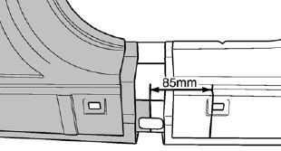
13 Rear Dog-leg Handy option. The lower cut measurement is the same as the rear quarter panel. Lower A Pillar Handy option also, plus has a method for partial replacement of the reinforcement. Check full A Pillar for lower cut measurement. Reinforcement Reinforcement 35mm 13


14 Sill panel options The sill panel has many cut options. Check the cut option that will best fit your repair. The reinforcement can also be sectioned so get full details for this method. Rear panel cut option No measurement given, the illustrations show the outer and inner panel option. Rear Rail The rear rail appears to have an OEM joint that can be used for fitting the rail end. 14
 SRS Air-Bag Refer to the SRS Air-Bag cautions information in general information Module 1.")

15 Body sealing and corrosion protection The BRM has full details on the joints to be sealed and the location of access holes for applying cavity wax. Product names are not given so duplicate with equivalent aftermarket product. Kia Rio (UB) SRS Air-Bag Refer to the SRS Air-Bag cautions information in general information Module 1. The illustration below shows the Air-Bag components used in the Rio. NVH Foam and Torque Settings NVH foam and the torque settings are not shown in the Picanto BRM manual. Overview The Picanto has some good repair options for a small vehicle, but perhaps this will change with a new model as the steels used for this model allow for a great range of repair. Side panels available The illustration below shows the partial side panel sections available for the Rio. 15


16 Steels used for the Rio body HSS is used for the doors boot lid, bonnet, guards and most all other structural panels. UHSS is shown for the B Pillar and cant rail reinforcement with mild steel used for side aperture panel. Partial replacement options The Rio has a good number of options. Front rail option Carrier mounting bracket Front rail option Panel gap and body measurements are given 16

 shown in")


17 Front rail continued A Pillar option The A Pillar outer and inner reinforcement can be replaced, the cut out sections (windows) shown in the illustration are for gaining access if replacing the reinforcement, you will require the full procedure when replacing the reinforcement. 17


18 B Pillar option The B Pillar outer requires a window cut in the upper cant rail panel if fitting the reinforcement. The reinforcement is made from UHSS so must be fitted at OEM joints and not sectioned, take care not to cut the reinforcement if removing the outer panel. Get the full method if replacing the reinforcement. Reinforcement CAUTION Always apply the spotweldable sealer between the centre pillar outer panel and centre pillar outer reinforcement, and also between the centre pillar outer reinforcement and centre pillar inner panel. CAUTION Always apply the spotweldable sealer between the centre pillar outer panel and centre pillar outer reinforcement, and also between the centre pillar outer reinforcement and centre pillar inner panel during installation. 18


19 Rear quarter panel Rear quarter panel is a straight forward cut and weld method with open butt welded joints. Has a hemmed non welded edge around the wheel arch. Hemmed wheel-arch Rear Dog-leg Handy option. The lower cut measurement is the same as the rear quarter panel. 19


20 Lower A Pillar Handy option. Also has method for partial replacement of the reinforcement. Check full A Pillar for lower cut measurement. Sill panel options The Rio has limited options for the sill panel, only the section in the front door opening is available. It also has a partial replacement option for the reinforcement (shown in the bottom illustration). Reinforcement Reinforcement Sill Reinforcement 20mm Reinforcement 20


21 Rear panel cut option The illustrations show the outer and inner panel option. Rear rail The rear rail appears to have an OEM joint that can be used for fitting the rail end. NVH Foam and Torque Settings NVH foam and the torque settings are not shown in the Rio BRM manual. Sealing and Corrosion protection The Rio has a very detailed section on sealing and corrosion protective wax installation. Overview The Rio has some good repair option. Inner rear panel 21


22 Kia Soul (PS) 2015 SRS continued SRS Air-Bag The supplemental restraint system (SRS) is designed to supplement the seat belt to help reduce the risk or severity of injury to the driver and passenger by activating and deploying the driver, passenger, side airbag and belt pretensioner in certain frontal or side collisions. The SRS (Airbag) consists of; a driver side airbag module located in the centre of the steering wheel, which contains the folded cushion and an inflator unit; a passenger side airbag module located in the passenger side crash pad contains the folded cushion assembled with inflator unit; side airbag modules located in the front seat contain the folded cushion and an inflator unit; curtain airbag modules located inside of the headliner which contains folded cushions and inflator units. WARNING/CAUTION labels are attached to the periphery of the air-bag components. Refer to the Shop Manual. SRS continued Side panels available The illustration below shows the partial side panel sections available for the Soul. The illustration shows the different parts of the SRS system; note the pressure sensors in the front door cavity. Tightening Torques Torque settings are given for the Soul mechanical. Below is an example for the Front Suspension taken from the BRM. Tightening torque (kgf.m) Nm kgf.m lb-ft Wheel Hub nuts 88.3 ~ ~ ~ 79.6 Wheel speed sensor mounting bolt 6.8 ~ ~ ~ 7.9 Wheel speed sensor wiring bracket bolt 8.8 ~ ~ ~


23 Strut assembly upper mounting nut 44.1 ~ ~ ~ 43.3 Strut assembly lower mounting bolt ~ ~ ~ Partial replacement options The Soul has a good number of options. Panel gap and body measurements are given in the BRM Front rail options Steels used for the Soul body HSS is used for the doors, boot lid, bonnet, guards and most all other structural panels. UHSS is shown for the B Pillar reinforcement and under floor rail with mild steel used for side aperture panel. Carrier mounting bracket Front rail full section option 23


24 Front rail partial A Pillar option The A Pillar outer and inner reinforcement can be replaced, the cut out sections (windows) shown in the illustration are for gaining access if replacing the reinforcement, you will require the full procedure when replacing the reinforcement. Reinforcement Reinforcement 24


25 B Pillar option The B Pillar outer requires a window cut in the upper cant rail panel if fitting the reinforcement. The reinforcement is made from UHSS so must be fitted at OEM joints and not sectioned, take not to cut if removing the outer panel. Get the full method if replacing the reinforcement. Lower sill joint B Lower sill joint C Reinforcement panel Reinforcement 25


26 Rear quarter panel Rear quarter panel is a straight forward cut and weld method with open butt welded joints. Has a hemmed non welded edge around the wheel arch. Rear Dog-leg Handy option. The lower cut measurement A is the same as the rear quarter panel. B is cut from the V shown in the illustration (no measurement is given). A B Inner dog-leg reinforcement option Reinforcement 26


27 Sill panel options The Soul has limited options for the sill panel, only the section in the front door opening is available. It also has a partial replacement option for the reinforcement (shown in the bottom illustration). Lower A Pillar Handy option, and also has method for partial replacement of the reinforcement. Check full A Pillar for lower cut measurement. Reinforcement Reinforcement Reinforcement Reinforcement 27

 4 and 5 door plus Koup 2014")


28 Rear panel cut option The illustrations show a straight cut through the rear panel with only one measurement. Kia Cerato (YD) 4 and 5 door plus Koup 2014 The Koup manual is 308 pages and contains all 3 models. Rear rail The rear rail appears to have an OEM joint that can be used for fitting the rail end. SRS Air-Bag Refer to the SRS Air-Bag cautions information in general information Module 1. The illustration below shows the Air-Bag components used in the Cerato. Overview The Rio has some good repair options. 28


29 Side panels available The illustration below shows the partial side panel sections available for the Cerato. Steels used for the Soul body HSS is used for the doors, boot lid, bonnet, guards and most all other structural panels. UHSS is shown for the B Pillar reinforcement and under floor rail with mild steel used for side aperture panel. Tightening Torque Torque settings are shown in the BRM for all bolt on Items and are very detailed. The following examples are for the Bonnet and door hinge. N.m Kgf.m lb-ft Front and rear doors Door hinge to body 33.3 ~ ~ ~ 30.4 Door hinge to door 21.6 ~ ~ ~ 19.5 Door checker to door 3.9 ~ ~ ~ 4.3 Door checker to body 19.6 ~ ~ ~ 21.7 The (YD) BRM has all measurements for the 3 body structures This also includes the body gaps. 29


30 Front rail option Body gap measurements Partial replacement options The Cerato has a good number of options. Front rail options Carrier mounting bracket 30


31 Upper apron panel A good option for partial replacement. No measurements are given so follow cut line shown in the illustration. A Pillar option The A Pillar outer and inner reinforcement can be replaced. The cut out sections (windows) shown in the illustration are for gaining access if replacing the reinforcement, you will require the full procedure when replacing the reinforcement. 31


32 B Pillar option The B Pillar outer requires a window cut in the upper cant rail panel if fitting the reinforcement. The reinforcement is made from UHSS so must be fitted at OEM joints and not sectioned, take care not to cut the reinforcement if removing the outer panel. Get the full method if replacing the reinforcement. Reinforcement panel Rear quarter panel The following illustrations show the replacement method for fitting the rear quarter of all 3 body styles. They have a hemmed wheel arch (check for glue around the wheel arch joint and replace if required). 4 Door Sedan A B 32


33 Rear quarter continued 5 door hatch continued 2 Door Koup 5 Door hatch 33


34 Hemmed wheel arch Lower A Pillar Handy option, and also has a method for partial replacement of the reinforcement. Check full A Pillar for lower cut measurement. Rear Dog-leg Handy option for the 4 and 5 door models. Lower measurement is the same as rear quarter joint. A No measurement given B Reinforcement Reinforcement 34


35 Sill panel options The Cerato has limited options for the sill panel; only the section in the front door opening is available. It also has a partial replacement option for the reinforcement (shown in the bottom illustration). Rear panel continued Rear rail The rear rail appears to have an OEM joint. No measurements are given. Rear panel cut option The illustrations show a straight cut through the rear panel with only one measurement. 35

 NZ has only released the 2 door model, however much of the BRM shows methods for the 5 door hatch, both models share the same platform.")

 Nm kgf.m lb-ft Wheel Hub nuts 88.3 ~ 107.9 9.0 ~ 11.0 65.1 ~ 79.")
36 NVH Foam and adhesive NVH foam and adhesives are not shown in the Cerato BRM manual. Overview The BRM for the Cerato is very informative plus has additional information not often include such as door and glass adjustments, seat-belts, seat parts removal operation. The dash pad and the components are also included. Pro-Ceed (JD) NZ has only released the 2 door model, however much of the BRM shows methods for the 5 door hatch, both models share the same platform. SRS Air-Bag Refer to the SRS Air-Bag cautions information in general information Module 1. The illustration below shows the Air-Bag components used in the 4 door Pro-Ceed. Torque settings Some of the settings for the front suspensions are shown in the example below. The BRM also has the wheel alignment settings Tightening torque (kgf.m) Nm kgf.m lb-ft Wheel Hub nuts 88.3 ~ ~ ~ 79.6 Strut assembly to frame 53.9~ ~ ~ 54.2 Strut assembly to knuckle ~ ~ ~ Strut assembly lock nut 58.8 ~ ~ ~ 50.6 Lower arm to sub frame (Front) 98.1 ~ ~ ~ 86.8 Lower arm to sub frame (Rear) ~ ~ ~


37 Wheel alignment The (JD) BRM has all measurements for the 3 body structures This also includes the body gaps. Steels used for the 4 door Pro-Ceed HSS is used for the doors, boot lid, bonnet, guards and most all other structural panels. UHSS is shown for the B Pillar reinforcement and under floor rail with mild steel used for side aperture panel. Partial replacement options The Pro-Ceed has a good number of options. 37


38 Front apron upper support This is a good option. Front rail option 38


39 A Pillar The A Pillar outer and inner reinforcement can be replaced. The cut out sections (windows) shown in the illustration are for gaining access if replacing the reinforcement, you will require the full procedure when replacing the reinforcement. Rear quarter panel 2 Door Only shows one measurement for the pillar joint, the rear sail panel is cut at the V on the flange and the lower joint lined up with the kick plate hole. 39


40 5 Door No measurement for the lower sill joint. Wagon The Pro-Ceed also has a wagon. No measurement given Wheel arch has hemmed edge 40


41 B Pillar The B Pillar outer requires a window cut in the upper cant rail panel if fitting the reinforcement, the reinforcement is made from UHSS so must be fitted at OEM joints and not sectioned. Take care not to cut the reinforcement if removing the outer panel. Get the full method if replacing the reinforcement. Nothing is shown for the 2 door model. Reinforcement No measurement given 41


42 Lower A Pillar Handy option, and also has a method for partial replacement of the reinforcement. Check full A Pillar for lower cut measurement. Rear dog-leg option Has option for the outer panel but nothing is shown for the reinforcement. Reinforcement 42


43 Sill panel options The Pro-Ceed has limited options for the sill panel; only the section in the front door opening is available. It also has a partial replacement option for the reinforcement (shown in the bottom illustration). Rear rail option The rear rail has reinforcement so a window is required to be cut out. Reinforcement 43


44 Rear Panel option Overview The Pro-Ceed has some good partial replacement options as well as having information not often seen, such as proceedure for removing the consol along with detailed information on seat belts and door trims etc. 44


45 Kia Optima (TF) Steels used for the Optima body HSS is used for the doors, boot lid, bonnet, guards and most all other structural panels. UHSS is shown for the B Pillar reinforcement and under floor rail with mild steel used for side aperture panel. SRS Air-Bag Refer to the SRS Air-Bag cautions information in general information Module 1. The illustration below shows the Air-Bag components used in the Optima. Side panels available The illustration below shows the partial side panel sections available for the Optima. Panel gap and body measurements are given in the BRM Tightening Torques Torque settings are given in the BRM (refer to dealer workshop manual) 45


46 Partial replacement options The Optima has some good options however some are a little more involved than the norm. Front rail continued Reinforcement Front rail The front rail option requires the inner reinforcement jointed at what appears to be an OEM joint. A Pillar The A pillar has 17 pages of instructions. If fitting the reinforcements a 3 layered sectioning joint is required as shown in the last illustration, get the full repair method if fitting a full A Pillar. The Optima also has a lower A Pillar outer and reinforcement option. 46


47 A Pillar lower section option Reinforcement 47


48 B Pillar The Optima B Pillar also has a 3 layered sectioning method for the sill reinforcements; get the full method before attempting this repair. B Pillar continued Reinforcement 48


49 Rear quarter panel Rear dog-leg option Reinforcement Hemmed wheel-arch 49


50 Sill panel options The Optima has limited options for the sill panel; only the section in the front door opening is available. It also has a partial replacement option for the reinforcement (shown in the bottom illustration). Rear rail option The rear rail appears to be joined at an OEM joint. Reinforcement NVH Adhesive and sealing The BRM for the Optima has very detailed illustrations of sealing and anti-corrosion requirements however NVH foams and adhesives are not included. 50
 SRS Air-Bag Refer to the SRS Air-Bag cautions information in general information Module 1.")
51 Overview The Optima has some good options however some of these are a little more involved than other methods recommended by Kia and should be considered at the time of preparing the estimate for repairs. Carens (RP) SRS Air-Bag Refer to the SRS Air-Bag cautions information in general information Module 1. The illustration below shows the Air-Bag components used in the Carens, note the pressure sensor for side impact? Side panels available The illustration below shows the partial side panel sections available for the Carens. 51


52 Tightening Torques Torque settings for bolt on parts are given in the BRM. The illustration shows the bonnet hinge tightening. Panel gap and body measurements are given in the BRM The following illustrations are an example of the information provided. Steels used for the Carens body HSS is used for the doors, boot lid, bonnet, guards and most all other structural panels. UHSS is shown for the B Pillar reinforcement and under floor rail with mild steel used for side aperture panel. Wheel alignment settings are also given in the BRM 52


53 Partial replacement options The BRM for the Carens has some good partial replacement options. Carrier mounting bracket Front rail front cut Rail to Bulk-Head at OEM joint 53


54 A Pillar The A pillar has 17 pages of instructions. If fitting the reinforcement get the full repair method. The Carens also has a lower A Pillar and reinforcement option. A Pillar Reinforcement joints Lower A Pillar only option 54


55 Reinforcement Reinforcement requires full replacement. Do not section. B Pillar outer 55


56 Rear quarter panel Rear quarter continued No measurement given Hemmed wheel arch Lower dog-leg, has outer only option 56


57 Sill panel The Carens has limited options for the sill panel; only the section in the front door opening is available. It also has a partial replacement option for the reinforcement (shown in the bottom illustration). Rear rail The rear cross-member end cap needs removing to replace the rear section of the rail. No measurement given Rear panel partial Reinforcement 57


58 NVH Adhesive and sealing The BRM for the Carens has very detailed illustrations of sealing and anti-corrosion requirements however NVH foams and adhesives are not included. Additional BRM information The Carens BRM has very detailed information on topics not often found in manuals such as the removal procedure for interior trims, door trims and window mechanism s, bonnet and boot panels. The seats are shown in detail along with a full section that covers all seat belts and the installation requirements. The illustrations below show an example of the door trim and seat construction information that is in the BRM. Overview The Carens has some good repair options along with some very detailed additional information not always shown in the BRM. It appears that more information is now being included for each new model produced. 58


59 Sportage (SL) Illustration showing side panel breakdown SRS Air-Bag Refer to the SRS Air-Bag cautions information in general information Module 1. The illustration below shows the Air-Bag components used in the Sportage, note the pressure sensor for side impact? There are differences between the 2 and 4 wheel drive Take care when ordering parts. Side panels available The illustration below shows the partial side panel sections available for the Sportage. The BRM has a full breakdown of all panels used for the Sportage body. Tightening Torques Torque settings for bolt on parts are not given in the BRM so refer to the Kia dealership workshop manual. Steels used for the Sportage body Steel grades used for the Sportage are not shown in the BRM so be sure to follow the recommended repair method shown if replacing welded panels. 59


60 Panel gap and body measurements are given in the BRM The following illustrations are an example of the information provided. Partial replacement options The BRM for the Sportage has some good partial replacement options. Front apron upper support This is a good option. 60


61 Front rail Front rail requires a window cut out for access to the reinforcement. Reinforcement Butt-weld joints Reinforcement 61


62 A Pillar The A Pillar has a 3 layer sectioning joint, so get the full repair method if fitting an A Pillar reinforcement. The Sportage also has a lower A Pillar and reinforcement option. A Pillar continued Reinforcement 62


63 B Pillar The B Pillar inner and outer can be sectioned; this requires cutting windows in the upper pillar and sill panels. The upper joint is 3 layers. Inner reinforcements Reinforcement Reinforcement 63


64 Rear quarter panel Rear quarter panel also has a lower dog-leg only option. Lower dog-leg option Outer panel only option; no option shown for sectioning the reinforcement. 64


65 Sill panel The Sportage has a good range of sill replacement options. Lower B Pillar and sill section Front door opening sill panel Reinforcement Reinforcement 65


66 Lower B Pillar reinforcement Rear rail Reinforcement Full outer sill panel replacement Reinforcement NVH and adhesives NVH and adhesives are not shown in the BRM however it does have a detailed section on sealing and corrosion protection application. Reinforcement Overview The Sportage has some good repair options; this is perhaps because the steels used don t limit what can be sectioned? 66


. Cleaning the epoxy adhesive area is important as dust or oiliness may greatly decrease the adhesive strength. 5.")
67 Sorento (UM12) Adhesives used in the Sorento Kia; Operation Procedures and Cautions in Using Epoxy Adhesives SRS Air-Bag Refer to the SRS Air-Bag cautions information in general information Module 1. The illustration below shows the Air-Bag used in the Sorento, also shown are the side impact sensor mounting locations, note the pressure sensor for side impact? Products stated in the BRM are (3m-PN8115) and (HENKEL Terokal 5055) Be sure to follow the instructions of the product you use Kia 1. Heat up the adhesive face on the panel to remove it. Heating temperature should be in the range of Use a torch or a heating gun. 2. Using a scraper, completely remove the remaining adhesive on the panel. 3. Using #50 - #80 sand paper, neatly grind off the adhesive area. Any remaining paint or surfacer must be removed from the adhesive area. 4. After grinding, clean the surface with a cleaner (adhesive cleaner). Cleaning the epoxy adhesive area is important as dust or oiliness may greatly decrease the adhesive strength. 5. Follow the same procedure of removing the paint and cleaning with a cleaner when applying adhesive on new panels. 6. Apply a light coat of adhesive on new panels or body panels, and then use a scraper to apply a second coat as thin as possible so that the metal surface is not visible (Skin coat). Ordinary adhesives are two-component types where the resin and hardener are filled in separate cartridges before being released from a nozzle or a gun. As the nozzle used for two-component type adhesive may harden after approximately 60 minutes without application, in case of delayed application, replace with a new nozzle. Check that the resin and hardener in the adhesive are released simultaneously before mounting the nozzle to the adhesive gun. This is important as nonsimultaneous release of resin and hardener may affect the hardening process. 7. Use the adhesive for a secondary application. The adhesive strength is generated on the panel in the secondary application in which the adhesive should be applied in a width of approximately 10mm. Apply in a width of 5 ó 6mm on flange areas. 8. Mount the panel onto the body. 67


68 9. After mounting the panel, use a clamp to firmly fix it so that there are no gaps or shaking. While the gaps and clearing of the panel may be adjusted before the adhesive is dry, caution is needed as adhesive must be applied again in case the mounted panel is detached. Maintain a distance of approximately 100 ó 150mm to the panel fixing clamp. 10. Using a scraper, remove any leaking adhesives during mounting process. As the adhesive is difficult to remove after it has been hardened, it must be removed before hardening. 11. Heat up the panel to harden. The adhesive is heat hardening type; it must be heated to harden. Steels used for the Sorento body HSS is used for the doors, boot lid, bonnet, guards and most all other structural panels. UHSS is shown for the Sill, A and B Pillar reinforcements plus the under floor and rear rails with mild steel used for side aperture and roof panels. Illustrations show where adhesive is used Welding When a damaged ultra high strength steel panel is replaced with a new one, spot welding should be used, if possible. Apply the epoxy adhesive and then carry out spot welding. 68


, Henkel (Terokal 5055) or equivalent.")

69 Measurements and panel gaps These are shown in the BRM with good illustrations. Partial replacement options The Sorento has some good options however some of these are very complex. Most of the panel replacement operations require some adhesive but be sure to check the BRM as the adhesive application is very specific. Example of adhesive application The following illustrations show the Kia instructions for the adhesive application. Torque settings Some of the settings for the front suspensions are shown in the example below. The BRM also has the wheel alignment settings. Adhesive Spot weld and MIG plug weld all holes, MIG lap weld the seam. If spot welding is impossible, MIG plug weld all holes. Apply epoxy adhesive to the weld points of new panel or body panel. Be sure to use the recommended epoxy adhesive. Epoxy adhesive : 3M(PN8115), Henkel (Terokal 5055) or equivalent. Tightening Torque Front Suspension Tightening torque (kgf.m) Nm kgf.m lb-ft Tire wheel hub nuts 88.3 ~ ~ ~ 79.6 Strut assembly to knuckle ~ ~ ~ Strut assembly lock nut 53.9 ~ ~ ~ 54.2 Lower arm to sub frame (Front) ~ ~ ~ Lower arm to sub frame (Rear) ~ ~ ~


70 Front rail options The BRM has 29 pages referring to the front rail replacement options. The following examples look at these options, the joint location and replacement methods required. Partial front rail bulkhead option continued Carrier mounting bracket Partial front rail forward section option Full rail replacement Partial front rail bulkhead option Reinforcement cut Reinforcement Assembly using weld bonding method 70


71 A Pillar continued A Pillar option The A Pillar has a 3 layer sectioning joint on the sill panel and the upper joint appears to be single layer. Reinforcements appear to be joined at the upper bulkhead region. Be sure to get the full method if replacing the reinforcement. Reinforcement joint location Reinforcement B Pillar replacement 71


72 Rear quarter panel Reinforcement panel 72


73 Adhesive used around wheel-arch Lower reinforcement Reinforcement Tailgate opening reinforcement joint Lower dog-leg option Another sill cut option given if replacing the inner panels Sill panel options The BRM does not show any options for the sill panel however the sill cut options for the A and B pillar and rear guard do have sectioning options as shown in the illustration. (Example only, check for the correct measurements) 73


74 Rear rail option The cross member end cap needs to be removed to allow access to the rail sectioning joint location. The join location appears to be at an OEM joint. Sealing and NVH The BRM has very detailed information on sealing and antivibration pads however it does not give the foam locations, the illustrations show examples from the BRM. Cavity Wax Injection Like most BRM for Kia, the Sorento also has very detailed cavity wax installation and show the application holes available. 74


75 Plastic Parts All plastic parts are identified along with a how to repair section. This is common for all Kia BRMs Carnival YP ANCAP The 2015 Carnival has limited sectioning options. This is perhaps because of the UHSS used for its construction. It is important to check if and where sectioning can be done as it appears this is limited to areas that are not UHSS panels. Overview The Sorento is a vehicle that uses a lot of UHSS so some repairs are perhaps limited. Along with this the Sorento uses a good amount of adhesive for replacing body panels. This is common for many new vehicles being manufactured today. SRS Air-Bag Refer to the SRS Air-Bag cautions information in general information Module 1. The following illustrations show the Carnival front and side impact sensor locations mounting note the pressure sensor for side impact? 75

.")
76 Adhesives used in the Sorento Kia; Operation Procedures and Cautions in Using Epoxy Adhesives Products stated in the BRM are (3m-PN8115) and (HENKEL Terokal 5055) Be sure to follow the instructions of the product you use Kia 1. Heat up the adhesive face on the panel to remove it. Heating temperature should be in the range of Use a torch or a heating gun. 2. Using a scraper, completely remove the remaining adhesive on the panel. 3. Using #50 - #80 sand paper, neatly grind off the adhesive area. Any remaining paint or surfacer must be removed from the adhesive area. 4. After grinding, clean the surface with a cleaner (adhesive cleaner). Cleaning the epoxy adhesive area is important as dust or oiliness may greatly decrease the adhesive strength. 5. Follow the same procedure of removing the paint and cleaning with a cleaner when applying adhesive on new panels. 6. Apply a light coat of adhesive on new panels or body panels, and then use a scraper to apply a second coat as thin as possible so that the metal surface is not visible (Skin coat). Ordinary adhesives are two-component types where the resin and hardener are filled in separate cartridges before being released from a nozzle or a gun. As the nozzle used for two-component type adhesive may harden after approximately 60 minutes without application, in case of delayed application, replace with a new nozzle. Check that the resin and hardener in the adhesive are released simultaneously before mounting the nozzle to the adhesive gun. This is important as nonsimultaneous release of resin and hardener may affect the hardening process. 7. Use the adhesive for a secondary application. The adhesive strength is generated on the panel in the secondary application in which the adhesive should be applied in a width of approximately 10mm. Apply in a width of 5 ó 6mm on flange areas. 8. Mount the panel onto the body. 9. After mounting the panel, use a clamp to firmly fix it so that there are no gaps or shaking. While the gaps and clearing of the panel may be adjusted before the adhesive is dry, caution is needed as adhesive must be applied again in case the mounted panel is detached. Maintain a distance of approximately 100 ó 150mmto the panel fixing clamp. 10. Using a scraper, remove any leaking adhesives during mounting process. As the adhesive is difficult to remove after it has been hardened, it must be removed before hardening. 11. Heat up the panel to harden. The adhesive is heat hardening type; it must be heated to harden. Illustrations show where adhesive is used 76


77 Torque settings Some of the settings for the rear suspensions are shown in the example below. The BRM also has the wheel alignment settings. Rear Suspension Tightening torque (kgf.m) Nm Kgf.m lb-ft Tire wheel Hub nuts 88.3 ~ ~ ~ 79.6 Trailing arm to body 98.1 ~ ~ ~ 86.8 Assist arm to sub frame ~ ~ ~ Assist arm to knuckle 68.6 ~ ~ ~ 39.8 Lower arm to knuckle ~ ~ ~ 61.6 Steels used for the Carnival body HSS is used for the doors, boot lid, bonnet, guards, floor, rails and most all other structural panels. UHSS is shown for the Sill A and B Pillar reinforcements plus the under floor and rear rails with mild steel used for side aperture and roof panel. Wheel Alignment Specification Front Rear Toe-in Individual 0.05 ± ±0.1 Total 0.1 ± ±0.2 Camber angle -0.5 ±0.5-1 ±0.5 Caster angle 4.14 ±0.5 - King-pin angle ±0.5 - Ride height mm ± 10mm ( ± in.) Body dimensions are given The BRM has a full section with very detailed information giving all the body dimensions and panel gaps. 77


78 Partial replacement options The Carnival has very limited partial replacement options. This is perhaps due to the increased use of UHSS. Always check if sectioning is permitted as it appears that this is never on UHSS panels. Most of the panel replacement operations require some adhesive but be sure to check the BRM as the adhesive application is very specific. Front rail The front rail only shows a full rail fitted at the OEM joint at the bulkhead. The carrier mounting bracket can be replaced as shown in the illustration. A Pillar replacement The A Pillar has a 3 layer sectioning joint on the sill panel and the upper joint appears to be single layer. Be sure to get the full method if replacing the reinforcement. When cutting the side sill outer reinforcement, take care not to cut through the matting flanges or the side sill inner reinforcement. 78


79 B Pillar option The B Pillar requires the full reinforcement cut into the upper roof rail. Note the front sill cuts are not cutting into the UHSS reinforcement. Reinforcement Reinforcement 79


80 B Pillar continued Rear quarter panel Reinforcement Sill panel options The BRM does not show any options for the sill panel apart from the sill cut options for the A and B Pillar and rear guard as shown in the illustration. (Example only, check for the correct measurements) 80


")


81 Inner quarter panels Sealing and NVH The BRM has very detailed information on sealing and anti-vibration pads however it does not give the foam locations, the illustrations show an example from the BRM. Rear panel The Carnival has a rear panel and rail end cap replacement method but no method is given for the rear rail. (Perhaps because they are UHSS) Cavity Wax Injection Like most BRM for Kia, the Carnival also has very detailed cavity wax installation and shows the application holes available. Overview The Carnival is very limited for partial replacement options. 81


82 Kia K2500 (PU) Light truck The K2500 has no body repair information; the Kia general repair instructions covered in Module 1 of this manual should be followed. K2500 Chassis dimensions Dimensions are available for both the 2 and 4 wheel drive models long and extra-long body. Cab options are; Standard cab Double cab King cab Note; This manual was developed as a quick reference tool showing the Kia replacement methods available for the current Kia fleet. This technical information is for fitting new genuine Kia parts only. Your local Kia dealerships are happy to provide the detailed repair information when ordering panel parts. 82
FOREWORD. Pub. No. RM029E RM427E
 FOREWORD This repair manual has been prepared as a supplement to TOYOTA SUPRA collision damaged repair manual to provide information on the repair methods (including cutting and welding operations, but
2008 Crown Victoria/Grand Marquis Workshop Manual. REMOVAL AND INSTALLATION Procedure revision date: 01/25/2010
 SECTION 501-35: Body Repairs 2008 Crown Victoria/Grand Marquis Workshop Manual REMOVAL AND INSTALLATION Procedure revision date: 01/25/2010 Ballistic Door Panel Special Tool(s) Heavy Duty Riveter 501-D011
Underbody Dimensions 4-Door 904
 Underbody Dimensions Wagon NOTE: Measurements are obtained on center, unless otherwise indicated. Underbody Dimensions 4-Door 904 SECTION 501-35: Body Repairs DESCRIPTION AND OPERATION Procedure revision
SRS AIRBAG Toyota RAV4. Supplemental Restraint System - RAV4 PRECAUTION CAUTION:
 2005 RESTRAINTS Supplemental Restraint System - RAV4 SRS AIRBAG PRECAUTION CAUTION: The TOYOTA RAV4 is equipped with SRS that includes a driver airbag, front passenger airbag, side airbag and curtain shield
General Motors. The Collision Repair Industry Leader.
 General Motors. The Collision Repair Industry Leader. This booklet provides you with detailed repair information. It is important to note that serviceability has been an integral part of the development
Body Repair News Fit: New Model Body Repair Information. June Applies To: Fit ALL
 Body Repair News Applies To: 2015 18 Fit ALL June 2017 2015 18 Fit: New Model Body Repair Information DISCLAIMER: This publication contains a summary of new body and vehicle technology that may affect
SP41A B-Pillar. Copyright 1999 Inter-Industry Conference On Auto Collision Repair v.4.0
 Uniform Procedures For Collision Repair SP41A B-Pillar 1. Description This procedure describes the repair and complete or partial replacement of an aluminum B-pillar assembly. Inspection and evaluation
SECTION Body Repairs
 501-35-i Body Repairs 501-35-i SECTION 501-35 Body Repairs CONTENTS PAGE Frame Members Front... 501-35-2 501-35-2 Body Repairs 501-35-2 Frame Members Front Special Tool(s) Rust Inhibitor Installation Kit
Bodyshop Manual GENERAL INFORMATION 00 PANEL REPLACEMENT 80C BODY STRUCTURE DIMENSIONS PLASTIC BODY PARTS 80F
 2009-2013 Bodyshop Manual FOREWORD This bodyshop manual is intended for use by technicians of Authorized Mazda Dealers to help them service and repair Mazda vehicles. It can also be useful to owners and
Introduction to Automotive Collision Repair Technology
 Introduction to Automotive Collision Repair Technology Introduction to Construction Materials Standard 01 Steel (Introduction to Construction Materials) Objective 01 I can explain steel strengths and the
SP06A Rail, Front Lower
 Uniform Procedures For Collision Repair SP06A Rail, Front Lower 1. Description This procedure describes the repair and complete or partial replacement of an aluminum front lower rail. Inspection and evaluation
Overview IMIARBBP13. Remove and Replace Motor Vehicle Body Panels Including Permanently Fixed Panels
 Overview This standard is about removing a variety of exterior and sub-structure body panels and panel sections, including permanently fixed panels, where these are damaged and replaced with new or repaired
Frame Members Rear. Special Tool(s) Rust Inhibitor Installation Kit Undercoating Spray Gun
 Rust Inhibitor Installation Kit Undercoating Spray Gun") SECTION 501-35: Body Repairs 2009 Mustang Workshop Manual REMOVAL AND INSTALLATION Procedure revision date: 04/03/2009 Frame Members Rear Special Tool(s) Rust Inhibitor Installation Kit 286-00002 Undercoating
SECTION 501-35: Body Repairs 2009 Mustang Workshop Manual REMOVAL AND INSTALLATION Procedure revision date: 04/03/2009 Frame Members Rear Special Tool(s) Rust Inhibitor Installation Kit 286-00002 Undercoating
2014-present. Bodyshop Manual GENERAL INFORMATION 00 PANEL REPLACEMENT 80C BODY STRUCTURE DIMENSIONS PLASTIC BODY PARTS 80F
 2014-present Bodyshop Manual FOREWORD This bodyshop manual is intended for use by technicians of Authorized Mazda Dealers to help them service and repair Mazda vehicles. It can also be useful to owners
Copyright 1999 Inter-Industry Conference On Auto Collision Repair v.4.0
 Uniform Procedures For Collision Repair DO21 Door Copyright 1999 Inter-Industry Conference On Auto Collision Repair v.4.0 1. Description This procedure describes the repair or replacement of a vehicle
Copyright 1999 Inter-Industry Conference On Auto Collision Repair v.4.0
 Uniform Procedures For Collision Repair UPCR SP08A Rail, Rear 1. Description This procedure describes the repair and complete or partial replacement of an aluminum rear rail. Inspection and evaluation
Body Repair News Accord: Body Repair Information. October Applies To: 2018 Accord ALL
 Body Repair News Applies To: 2018 Accord ALL October 2017 2018 Accord: Body Repair Information DISCLAIMER: This publication contains a summary of new body and vehicle technology that may affect collision
FOREWORD. Applicable models: GSJ 10, 15 series
 FOREWORD This repair manual has been prepared to provide essential information on body panel repair methods (including cutting and welding operations, but excluding painting) for the TOYOTA FJ CRUISER.
MODEL/YEAR MODÈLE /ANNÉE TL: Body Repair Information
 MODEL/YEAR MODÈLE /ANNÉE DATE OF ISSUE DATE EN VIGUEUR BULLETIN NUMBER NUMÉRO DU BULLETIN Body Repair News 2009 TL APRIL 25, 2014 BRN-14-2 2009 TL: Body Repair Information DISCLAIMER: This publication
SP91S Trunk Floor. Copyright 1999 Inter-Industry Conference On Auto Collision Repair v.4.0
 Uniform Procedures For Collision Repair SP91S Trunk Floor Copyright 1999 Inter-Industry Conference On Auto Collision Repair v.4.0 1. Description This procedure describes the repair and complete or partial
OPR Replacement Foxbody Floor Pans Pair (79-93 All)
") OPR Replacement Foxbody Floor Pans Pair (79-93 All) Time Necessary: Approximately 40-hours Tools Required: Spot Weld Cutter Tool Corded Drill Center Punch MIG Welder (minimum recommended: 110VAC/135A)
OPR Replacement Foxbody Floor Pans Pair (79-93 All) Time Necessary: Approximately 40-hours Tools Required: Spot Weld Cutter Tool Corded Drill Center Punch MIG Welder (minimum recommended: 110VAC/135A)
Airbags, servicing. Airbag system, safety precautions WARNING!
 Page 1 of 75 69-40 Airbags, servicing Airbag system, safety precautions Checking, removing, installing and servicing may ONLY be performed by qualified personnel. Never perform tests using a test light
NATEF Task List - Collision Repair & Refinish Non-Structural Analysis & Damage Repair
 For every task in Non-Structural Analysis and Damage Repair, the following safety requirements must be strictly enforced: Comply with personal and environmental safety practices associated with clothing
SP01A Rail, Front Upper
 Uniform Procedures For Collision Repair UPCR SP01A Rail, Front Upper 1. Description This procedure describes the repair and complete or partial replacement of an aluminum front upper rail. Inspection and
GENERAL VEHICLE INFORMATION FRONT LOWER STRUCTURE CENTRE LOWER STRUCTURE UPPER FRONT STRUCTURE NON-SIDE OPENING ELEMENTS
 4 Panelwork 40A GENERAL VEHICLE INFORMATION 41A FRONT LOWER STRUCTURE 41B CENTRE LOWER STRUCTURE 41C SIDE LOWER STRUCTURE 41D REAR LOWER STRUCTURE 42A UPPER FRONT STRUCTURE 43A SIDE UPPER STRUCTURE 44A
1997/98 Corvette. Panel Identification Front Bumper Impact Bar Front Wheelhouse Rail - Underbody Side Assembly...
 1997/98 Corvette Panel Identification...3-1 Front Bumper Impact Bar...3-2 Front Wheelhouse...3-4 Rail - Underbody Side Assembly...3-6 Front Side Door Opening Assembly...3-17 Windshield Frame Assembly...3-19
Technical Committee July 21,2011 Salt Lake City, Utah
 Technical Committee July 21,2011 Salt Lake City, Utah A 2010 Toyota XB with Damage to the Driver s Side There is damage to the rocker & outer B pillar-lower section Let s Write the sheet Set up frame machine
FR11A Fender, Welded-On
 Uniform Procedures For Collision Repair FR11A Fender, Welded-On 1. Description This procedure describes the repair and complete replacement of a welded-on aluminum fender. Inspection and evaluation requirements
MODEL/YEAR MODÈLE /ANNÉE ACCORD: New Model Body Repair Information
 Body Repair News MODEL/YEAR MODÈLE /ANNÉE DATE OF ISSUE DATE EN VIGUEUR BULLETIN NUMBER NUMÉRO DU BULLETIN 2018 ACCORD DEC. 19, 2017 J-6-17 2018 ACCORD: New Model Body Repair Information DISCLAIMER: This
Next Generation Methods Explained
 The following will feature overviews of each type of methods page with each element identified. There are different types of pages that exist in each document: the first page of the method, if applicable
FR11S Fender, Welded-On
 Uniform Procedures For Collision Repair UPCR FR11S Fender, Welded-On 1. Description This procedure describes the repair and complete replacement of a welded-on steel fender. Inspection and evaluation requirements
IDENTIFYING THE TYPE OF CLARITY MODEL
 Body Repair News December, 2017 07817 Version 3 2017 18 Clarity Series New Model Body Repair Information This publication contains a summary of new body and vehicle technologies that may affect collision
JK8 Body Kit KIT CONTENTS 1 K
 JK8 Body Kit KIT CONTENTS A B C 1 K6861352 D E G F H 2 K6861352 I M N J K L O P Q R S 3 K6861352 T U V W X Y CALL OUT PART NUMBER DESCRIPTION QUANTITY A P5156021 HARDTOP 1 B P5155997 BULKHEAD 1 C 1PH98/9TZZAE
Copyright 1999 Inter-Industry Conference On Auto Collision Repair v.4.0
 Uniform Procedures For Collision Repair DO31P Skin Copyright 1999 Inter-Industry Conference On Auto Collision Repair v.4.0 1. Description This procedure describes the complete or partial replacement of
CP01S Corrosion Protection
 Uniform Procedures For Collision Repair CP01S Corrosion Protection 1. Description This procedure describes repair methods and inspection requirements for the application of corrosion protection materials
Body Repair News RDX: Body Repair Information (Supersedes original publication issued December Revision includes 2016 model info)
") Body Repair News Applies To: 2013 RDX Model Series ALL April 2015 2013 RDX: Body Repair Information (Supersedes original publication issued December 2013. Revision includes 2016 model info) DISCLAIMER:
Body Repair News Applies To: 2013 RDX Model Series ALL April 2015 2013 RDX: Body Repair Information (Supersedes original publication issued December 2013. Revision includes 2016 model info) DISCLAIMER:
BODY CONSTRUCTION A-1 CONTENTS BODY COMPONENTS... 2 BODY MAIN CROSS-SECTIONAL VIEWS. 4 SILENCER APPLICATION LOCATIONS.. 21
 A- BODY CONSTRUCTION CONTENTS BODY COMPONENTS... BODY MAIN CROSS-SECTIONAL VIEWS. MAINTENANCE, SERVICEABILITY... BODY CONSTRUCTION CHARACTERISTICS... 8 FRONT BODY... 8 SIDE BODY... REAR BODY... ROOF...
Copyright 1998 Inter-Industry Conference On Auto Collision Repair v.4.0
 Uniform Procedures For Collision Repair DO01 Hinges 1. Description This procedure describes the replacement of door hinges. Inspection and evaluation requirements are also included. 2. Purpose The purpose
SUPPLEMENTAL RESTRAINT SYSTEM
 PRECAUTION CAUTION: The COROLLA MATRIX is equipped with SRS, which comprises a driver airbag, front passenger airbag, and side airbag. Failure to carry out service operations in the correct sequence could
HOW TO USE THIS MANUAL
 INTRODUCTION IN-5 HOW TO USE THIS MANUAL 1. BODY PANEL REPLACEMENT THIS MANUAL BP-34 BODY PANEL REPLACEMENT QUARTER PANEL (CUT) REPLACEMENT REMOVAL POINT 1 Remove the [A] at the same time. PART NAME [A]
Roll Cage Installation Notes
 Roll Cage Installation Notes Introduction The regulations state that you have to fit one of 3 versions of Safety Devices 6 point bolt-in cage. The items you need are shown below: Option 1 Part Number RBC052
Panel Bonding Adhesive
 Panel Bonding Adhesive Technical Data August 2017 Product Description 3M Panel Bonding Adhesive is a two-part epoxy adhesive which provides extended work-time but can be rapidly cured with heat. 3M Panel
FOREWORD. Applicable models: JZA80 series
 FOREWORD This repair manual has been prepared to provide information on the repair methods (including cutting and welding operations, but excluding painting) for collision-damaged body components of the
SUPPLEMENTAL RESTRAINT SYSTEM
 PRECAUTION CAUTION: HIGHLANDER is equipped with SRS, which consists of a driver airbag, front passenger airbag, side airbag and curtain shield airbag. Failure to carry out service operations in the correct
BODY & TRIM SECTIONBT CONTENTS. . For seat belt, refer to MA and RS section.. For wiring diagrams of body electrical systems, refer to EL section.
 BODY & TRIM SECTIONBT CONTENTS PRECAUTIONS...1 Service Notice...1 Supplemental Restraint System (SRS) AIR BAG and SEATBELTPRE-TENSIONER...1 GENERAL SERVICING...2 Clip and Fastener...2 BODY END...4 Body
Restoring Corrosion Protection Following Repair
 SECTION 501-35: Body Repairs 2009 Mustang Workshop Manual GENERAL PROCEDURES Procedure revision date: 09/05/2008 Restoring Corrosion Protection Following Repair Special Tool(s) Rust Inhibitor Installation
Body Repair News MDX: New Model Body Repair Information. September Applies To: 2014 MDX Model Series ALL
 Body Repair News Applies To: 2014 MDX Model Series ALL September 2013 2014 MDX: New Model Body Repair Information DISCLAIMER: This publication contains a summary of new body and vehicle technology that
1. General Description
 General Description 1. General Description A: COMPONENT (1) (2) (3) (4) (5) (6) (7) (8) (9) (10) (24) (23) (22) (21) (20) (19) (18) (17) (16) (15) (14) (13) (12) (11) AB-02007 (1) Curtain airbag module
Sheet metal work. Mechanisms and accessories
 Sheet metal work GENERAL LOWER STRUCTURE UPPER SIDE STRUCTURE UPPER REAR STRUCTURE TOP OF BODY Mechanisms and accessories EXTERIOR PROTECTION JE0 AL - JE0 EL - JE0 HL 77 11 196 742 DECEMBER 1997 Edition
Before repairs, remove the airbag sensor if shocks are likely to be applied to the sensor during repairs.
 NOTICE: When inspecting or repairing the SRS, perform the operation in accordance with the following precautionary instructions and the procedure and precautions in the Repair Manual for the applicable
The Core Four Solutions
 3M Tech Talk: The Core Four Solutions to Complete Corrosion Protection Have you ever seen a vehicle that has corrosion on only one panel? Do you then wonder why just one panel has corroded while the same
GENERAL INFORMATION HANDLING PRECAUTIONS
 BODY BO1 BO2 BODY GENERAL INFORMATION GENERAL INFORMATION HANDLING PRECAUTIONS Taping When it is possible that the body or parts may be scratched during the operation, apply protective tape before starting
WE51S Squeeze-Type Resistance Spot Weld
 Uniform Procedures For Collision Repair WE51S Squeeze-Type Resistance Spot Weld 1. Description This procedure describes methods for making and evaluating squeeze-type resistance spot welds (STRSW) on automotive
8. Front Bumper. Front Bumper A: REMOVAL EI FRONT BUMPER FACE. 5) For OUTBACK model, remove the side garnish of the front fender.
 For OUTBACK model, remove the side garnish of the front fender.") 8. A: REMOVAL 1. FRONT BUMPER FACE 1) Disconnect the ground cable from the battery. 2) Turn over the front mud guard, and remove the clips connecting the fender and bumper. 5) For OUTBACK model, remove
8. A: REMOVAL 1. FRONT BUMPER FACE 1) Disconnect the ground cable from the battery. 2) Turn over the front mud guard, and remove the clips connecting the fender and bumper. 5) For OUTBACK model, remove
AEB Fitment - Available. BMW 7 series. image source: BMW
 factor volumes AEB Fitment - Available BMW 7 series The 7 series is the 6 th generation of BMW s flagship luxury model, introducing many new technologies including Carbon Core CFRP (Carbon Fibre Reinforced
SRS AIRBAG PRECAUTION
 SRS AIRBAG PRECAUTION SRS AIRBAG The LEXUS ES300 is equipped with SRS, which comprises a driver airbag and a front passenger airbag. Failure to carry out service operations in the correct sequence could
TECHNICIAN SAFETY INFORMATION
 2009 Honda Accord L4-2.4L Vehicle > Restraints and Safety Systems > Air Bag Systems > Service Precautions TECHNICIAN SAFETY INFORMATION SRS Precautions and Procedures General Precautions NOTE: Some systems
Copyright 1999 Inter-Industry Conference On Auto Collision Repair v.4.0
 Uniform Procedures For Collision Repair UPCR SP11S Frame Copyright 1999 Inter-Industry Conference On Auto Collision Repair v.4.0 1. Description This procedure describes the repair and complete or partial
MODEL/YEAR MODÈLE /ANNÉE CR-V: New Model Body Repair Information
 Body Repair News MODEL/YEAR MODÈLE /ANNÉE DATE OF ISSUE DATE EN VIGUEUR BULLETIN NUMBER NUMÉRO DU BULLETIN 2012 CR-V Dec. 11, 2017 J-3-17 2012 CR-V: New Model Body Repair Information DISCLAIMER: This publication
Body Repair News MDX: New Model Body Repair Information. August Applies To: 2014 MDX Model Series ALL
 Body Repair News Applies To: 2014 MDX Model Series ALL August 2014 2014 MDX: New Model Body Repair Information DISCLAIMER: This publication contains a summary of new body and vehicle technology that may
Water Leak At Back Door Hatch
 T-SB-0008-12 January 6, 2012 Service Category Vehicle Exterior Section Door/Hatch Market USA Applicability YEAR(S) MODEL(S) ADDITIONAL INFORMATION 2006 2007 Highlander HV 2001 2007 Highlander Introduction
2004 Toyota RAV ACCESSORIES/SAFETY EQUIPMENT Toyota - Air Bag Restraint Systems
 DESCRIPTION & OPERATION 2004 ACCESSORIES/SAFETY EQUIPMENT Toyota - Air Bag Restraint Systems WARNING: Accidental air bag deployment is possible. Personal injury may result. Read and follow all WARNINGS
DESCRIPTION & OPERATION
 AIR BAG RESTRAINT SYSTEM 1996 ACCESSORIES/SAFETY EQUIPMENT Toyota Air Bag Restraint System DESCRIPTION & OPERATION WARNING: To avoid injury from accidental air bag deployment, read and carefully follow
FOR ALL OF VEHICLES PRECAUTION
 IN10 PRECAUTION IN0FA01 1. FOR VEHICLES EQUIPPED WITH SRS AIRBAG AND SEAT BELT PRETENSIONER (a) The CELICA is equipped with an SRS (Supplemental Restraint System), such as the driver airbag, front passenger
INSTALLATION INSTRUCTIONS
 INSTALLATION INSTRUCTIONS Accessory S P/N 08V67-SJC-101 Application 2012 RIDGELINE Publications No. AII 12006 Issue Date NOV 2011 PARTS LIST Back-up sensor harness 3 Wire ties with small clips (2 Not used)
Revised April High School Graduation Years 2016, 2017 and 2018
 Unit/Standard Number High School Graduation Years 2016, 2017 and 2018 Autobody/Collision and Repair Technology/Technician CIP 47.0603 Task Grid Secondary Competency Task List 100 SAFETY 101 Establish general
GENERAL GUIDELINES FOR THE APPLICATION OF TECTYL AUTO/TRUCK/TRAILER RUSTPROOFING COMPOUNDS
 Number 17 GENERAL GUIDELINES FOR THE APPLICATION OF TECTYL AUTO/TRUCK/TRAILER RUSTPROOFING COMPOUNDS A. Equipment 1) Airless type spray equipment, designed for fluid pressure atomization. The spray gun
INSTALLATION INSTRUCTIONS
 INSTALLATION INSTRUCTIONS Accessory S P/N 08V67-SJC-101 Application 2010 RIDGELINE Publications No. AII 42117 Issue Date AUG 2009 PARTS LIST Back-up sensor harness 3 Wire ties with small clip (2 Not used)
Copyright 1998 Inter-Industry Conference On Auto Collision Repair v.4.0
 Uniform Procedures For Collision Repair DO22 Door, Sliding 1. Description This procedure describes the repair or replacement of a sliding door. Inspection and evaluation requirements are also included.
Airbags and Pretensioners
 Airbags and Pretensioners Emergency Response Guide GM Service Technical College provides First Responder Guides (FRG) and Quick Reference (QR) Sheets free of charge to First Responders. FRGs and QRs can
Vivaro Conversion Recommendations. List of contents
 List of contents 1 Conversion limitations for platform chassis... 1 Wheel base extension... 1 Replacing brake lines... 1 Parking brake... 2 Wheel base shortening... 7 Rear overhang... 10 Additional corrosion
SECTION ZF FRONT AXLE
 04-101.01/ 1 2011JA14 SECTION 04-101.01 6 3 5 1 2 9 1. Upper radius rod 2. Lower radius rod 3. Caliper 4. BRAKE Disk 5. Pneumatic connector 6. Hub 7. steering knuckle 8. Grease Fitting 9. Pneumatic connector
SEAT BELT WARNING SYSTEM
 SEAT BELT SEAT BELT WARNING SYSTEM 1 SEAT BELT WARNING SYSTEM System Name Power window control system (with Jam Protection Function) Sliding Roof System PRECAUTION When disconnecting the cable from the
INSTALLATION INSTRUCTIONS
 INSTALLATION INSTRUCTIONS Accessory Application Publications No. BII 31129 REARVIEW CAMERA 2006 RL Issue Date OCT 2005 PARTS LIST Attachment Kit P/N: 08B21-SJA-B00 Template Rear camera trim 6-Pin connector
Air Bag and Safety Belt Pretensioner Supplemental Restraint System (SRS)
") Page 1 of 26 Published : Mar 16, 2005 Air Bag and Safety Belt Pretensioner Supplemental Restraint System (SRS) COMPONENT LOCATIONS, SHEET 1 OF 2 Item Part Number Description 1 - SRS (supplemental restraint
Page 1 of 26 Published : Mar 16, 2005 Air Bag and Safety Belt Pretensioner Supplemental Restraint System (SRS) COMPONENT LOCATIONS, SHEET 1 OF 2 Item Part Number Description 1 - SRS (supplemental restraint
Before repairs, remove the airbag sensor if shocks are likely to be applied to the sensor during repairs.
 NOTICE: When inspecting or repairing the SRS, perform the operation in accordance with the following precautionary instructions and the procedure and precautions in the Repair Manual for the applicable
SPECIAL TECHNICAL PRESENTATION. Oklahoma City, Ok April 2012
 SPECIAL TECHNICAL PRESENTATION Oklahoma City, Ok April 2012 How governmentregulations will affect your body shop business? What is CAFÉ? CAFÉ stands for Corporate Average Fuel Economy What are the CAFÉ
Advanced High-Strength Steel Vehicle Collision Repairability
 Advanced High-Strength Steel Vehicle Collision Repairability Steve Marks Industry Technical Support Manager I-CAR Tech Center Who Is I-CAR? Inter-Industry Conference On Auto Collision Repair Not-For-Profit
Model Year: 2008 Model: xb Doc ID: RM000000SUR00OX. (a) Using a scraper, remove the damaged stoppers, dam and adhesive from the windshield glass.
 Using a scraper, remove the damaged stoppers, dam and adhesive from the windshield glass.") WINDSHIELD / WINDOWGLASS: WINDSHIELD GLASS: INSTALLATION (2008 x... Page 1 of 10 Last Modified: 2-12-2007 Service Category: Vehicle Exterior 1.6 A Section: Window/Glass Model Year: 2008 Model: xb Doc ID:
WINDSHIELD / WINDOWGLASS: WINDSHIELD GLASS: INSTALLATION (2008 x... Page 1 of 10 Last Modified: 2-12-2007 Service Category: Vehicle Exterior 1.6 A Section: Window/Glass Model Year: 2008 Model: xb Doc ID:
Maintenance Agent Maintenance Chemicals 1
 Maintenance Agent Maintenance Chemicals 1 00492 Engine Room Wipe 10 sheets These newly developed sheets are hard to get stuck and be shaped into a ball, which allows for more efficient absorption of unwanted
INSTALLATION INSTRUCTIONS
 INSTALLATION INSTRUCTIONS Accessory S Application 2010 ODYSSEY Publications No. AII 41818 Issue Date JUNE 2009 PARTS LIST Right center sensor clip (Black) Backup Sensor Attachment Kit P/N 08V67-SHJ-101C
BODY REPAIR SECTION BRM CONTENTS BODY EXTERIOR, DOORS, ROOF & VEHICLE SECURITY BRM-1 FEATURES OF NEW MODEL... 2 PRECAUTION... 3 ON-VEHICLE REPAIR...
 BODY EXTERIOR, DOORS, ROOF & VEHICLE SECURITY SECTION BRM A BODY REPAIR B C D CONTENTS E FEATURES OF NEW MODEL... 2 BODY EXTERIOR PAINT COLOR... 2 Body Exterior Paint Color...2 PRECAUTION... 3 HANDLING
FOR ALL OF VEHICLES PRECAUTION
 INTRODUCTION PRECAUTION IN9 1. FOR VEHICLES EQUIPPED WITH SRS AIRBAG (a) The 4RUNNER is equipped with an SRS (Supplemental Restraint System), such as the driver airbag, front passenger airbag and seat
Collision Position Statements Date: June,
 Collision Position Statements GLOSSARY Use of Non-OEM Parts Reference: NPSB-16-594 Nissan Wheel Repair Reference: NPSB-16-595 Bumper Fascia Replacement with Sonar Reference: NPSB-16-596 Radar Recalibration
SHARK UPPER WINDSHIELD FRAME & WINDSHIELD REPLACEMENT. Text and Photos by TOM BENFORD
 Text and Photos by TOM BENFORD I purchased a fathom green 69 big-block tri-power T-top coupe with only 42,000 original miles on it recently. I'm the third owner of the car, and I got it for a very good
8. Front Bumper. Front Bumper A: REMOVAL EI FRONT BUMPER BEAM ASSEMBLY 1. FRONT BUMPER FACE
 8. A: REMOVAL 1. FRONT BUMPER FACE 1) Disconnect the ground cable from the battery. 2) Remove the front grille. 3) Turn over the front mud guard, and remove the
FR01A Fender, Bolted-On
 Uniform Procedures For Collision Repair UPCR FR01A Fender, Bolted-On 1. Description This procedure describes the repair and complete replacement of a bolted-on aluminum fender. Inspection and evaluation
LINCOLN. Continental 1
 3154_U01.qxd 8/1/03 7:28 AM Page 1 Continental 1 BRAKES...1-27 DRIVE TRAIN...1-21 ENGINE REPAIR...1-7 FUEL SYSTEM...1-20 PRECAUTIONS...1-7 SPECIFICATION CHARTS...1-2 STEERING AND SUSPENSION...1-22 A Air
9-2 In case of emergency
 In case of emergency If you park your vehicle in case of an emergency... 9-2 Temporary spare tire... 9-2 Maintenance tools... 9-3 Flat tires... 9-5 Changing a flat tire... 9-5 Tire pressure monitoring
FOREWORD RM029E RM027E RM036E EWD013E. M/Y Version. M/Y Version BRM002E 36438E
 FOREWORD 1 This repair manual has been prepared to provide information on the repair methods (including cutting and welding operations, but excluding painting) recommended by TOYOTA for collision damaged
SEAT BELT WARNING SYSTEM
 WARNING SYSTEM LOCATION WARNING SYSTEM 611 6105001 Combination Meter (Driver s Seat Belt Warning Lamp) Clock Assy (Passenger s Seat Belt Warning Lamp) Seat Belt Warning Sensor Front Seat Inner Belt Assy
2018 Honda Accord Hybrid Emergency Response Guide
 2018 Honda Accord Hybrid Emergency Response Guide Prepared for Fire Service, Law Enforcement, Emergency Medical, and Professional Towing Personnel 2018 American Honda Motor Co., Inc. All Rights Reserved.
SR11 Steering, Rack-And-Pinion
 Uniform Procedures For Collision Repair SR11 Steering, Rack-And-Pinion SR Menu Procedure Menu 1. Description This procedure describes diagnosis, replacement, and inspection of a rack-and-pinion steering
INSTALLATION INSTRUCTIONS
 INSTALLATION INSTRUCTIONS Accessory Application CR-V Publications No. AII 32953-34081 Issue Date NOV 2006 PARTS LIST 2 Corner sensor clips Backup Sensor Attachment Kit P/N 08V67-SWA-100A Back-up sensor
SUPPLEMENTAL RESTRAINT SYSTEM
 PRECAUTION CAUTION: PRIUS is equipped with SRS, which consists of a driver airbag, front passenger airbag, side airbag and curtain shield airbag. Failure to carry out service operations in the correct
2004 IMPREZA SERVICE MANUAL QUICK REFERENCE INDEX
 2004 IMPREZA SERVICE MANUAL QUICK REFERENCE INDEX BODY SECTION HVAC SYSTEM (HEATER, VENTILATOR AND A/C) HVAC SYSTEM (AUTO A/C) (DIAGNOSTICS) AC AC(diag) AB This service manual has been prepared to provide
BODY (INTERIOR AND EXTERIOR)
") BODY (INTERIOR AND EXTERIOR) Return to Main Table of Contents GENERAL... 2 BODY PANELING... 7 HOOD... 12 GRILLE AND MOULDINGS... 14 BUMPER... 16 FENDER... 19 WINDSHIELD... 21 REAR WINDOW GLASS... 25 FRONT
BODY (INTERIOR AND EXTERIOR) Return to Main Table of Contents GENERAL... 2 BODY PANELING... 7 HOOD... 12 GRILLE AND MOULDINGS... 14 BUMPER... 16 FENDER... 19 WINDSHIELD... 21 REAR WINDOW GLASS... 25 FRONT
FUEL SYSTEM SECTION CONTENTS B ENGINE FL-1
 B ENGINE A SECTION FUEL SYSTEM FL C D CONTENTS E PRECAUTIONS... 2 Precautions for Supplemental Restraint System (SRS) AIR BAG and SEAT BELT PRE-TEN- SIONER... 2 PREPARATION... 3 Special Service Tools...
Perkins Statewide Articulation Agreement. Documentation item: Secondary Competency Task List Coversheet
 Perkins Statewide Articulation Agreement Documentation item: Secondary Task List Coversheet The Secondary School agrees to: A. Implement the approved PDE Program(s) of Study. B. Provide assessment of student
INSTALLATION GUIDE AOI0020. aoielectrical.com IMPALA, 2011+CHEVY CAPRICE FORD F FORD EXPLORER
 INSTALLATION GUIDE AOI0020 2001-2014 IMPALA, 2011+CHEVY CAPRICE 2007-2013 FORD F150 2007-2013+ FORD EXPLORER 2013+ FORD UTILITY/ SEDAN INTERCEPTOR 2007-2013+ DODGE CHARGER 2007-2013+DURANGO 2008-2013+