Upgrading TriMark IEI RF Controller to TriMark Full-Feature RF Controller
|
|
|
- Amos O’Neal’
- 6 years ago
- Views:
Transcription
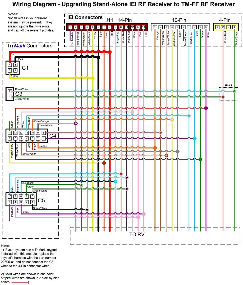
1 Rewiring Guide This guide explains how to upgrade from the discontinued IEI RF Controller to the TM-FF Controller. Use the tables explaining each wire s location and purpose for the old and new modules in conjunction with the equivalency spreadsheet and schematic for the recommended retrofit installation. Wire colors for the original installation may not match those mentioned in this guide, so reference only the parent connector and pin location when matching up wires. IEI Wiring Definitions This table details what each wire s purpose, parent connector, and pin location is for the original equipment installation. The default factory color is called out, but your installation may differ if the OEM provided integrated harnesses. IEI RF Module Connector Names and Locations 1
2 TM-Full Feature (FF) Wiring Definitions This table details what each wire s purpose, its parent connector, and its pin location for the TM-FF RF Module. The wire colors called out in this table are accurate if you ve purchased the kit including pigtail harnesses. Wire colors will vary if you ve purchased an adaptor harness from a manufacturer other than TriMark. TM-FF RF Module Connector Names and Locations IEI RF Module Wire Definitions 1 2 J11 Connector AUX 12A Relay Input/Output (Fuse is recommended) AUX 12A Relay Input/Output (Pin 1 and Pin 2 are interchangeable) Default Wire Color PURPLE / WHITE PURPLE / WHITE 3 LOCK Output (N / C Relay 30) WHITE / GREEN 4 LOCK Input (N / C Relay 87A) WHITE / BLACK 5 Connect to TRUE IGNITION YELLOW 6 Connect to CLEAN GROUND BLACK 7 SIREN (+) Output, Up to 2A BROWN 8 Connect to POWER SOURCE (Fuse Recommended) RED 9 UNLOCK Input (N / C Relay 87A) BLUE / WHITE 10 UNLOCK Output (N / C Relay 30) WHITE / RED 11 LOCK / UNLOCK Polarity (N / O Relay 87) PINK / BLACK 12 PARKING LIGHTS Output (+12V, 15A) WHITE DOME LIGHT 12A Relay Input/Output (Fuse is recommended) DOME LIGHT 12A Relay Input/Output (Pin 13 and Pin 14 are interchangeable) PINK PINK 10-Pin Connector Default Wire Color 1 ARMED Output (-) 500mA ORANGE 2 AUX. CHANNEL #2 (-) 500mA WHITE / BROWN 3 HORN Output (-) 500mA BROWN / WHITE 4 2 nd UNLOCK Output (-) 500mA WHITE / YELLOW 5 HEADLIGHTS Output (-) 500mA GRAY 6 UNASSIGNED PURPLE / GREEN 7 STAGGERED LOCK (-) 500mA WHITE / BLUE 8 (-) 2 nd UNLOCK Signal Input BLUE 9 (-) Door Trigger Input GREEN 10 (+) Door Trigger Input PURPLE 4-Pin Connector Default Wire Color 2 (-) UNLOCK SIGNAL Input WHITE / RED 4 (-) LOCK SIGNAL Input WHITE / GREEN CN2 & CN3 STARTER KILL Relay Non-Polarized, 40A 0.25 Male Connectors none 2
3 TM-FF RF Module Wire Definitions C1: 4-PIN HARNESS Default Wire Color None 2 IGNITION Input YELLOW 3 GROUND Input BLACK 4 POWER (+12V) Input RED C2: KEYPAD HARNESS Default Wire Color --- Pre-Made Harness (p/n or ) --- C3: 2-PIN HARNESS Default Wire Color 1 (-) LOCK SIGNAL Input GREEN / WHITE 2 (-) UNLOCK SIGNAL Input BLUE / WHITE C4: 14-PIN HARNESS Default Wire Color 1 (-) SECURITY TRIGGER Input 3 WHITE / PURPLE 2 ARMED Output (-500mA) ORANGE 3 STARTER KILL Output (-500mA) BROWN 4 HEADLIGHTS Output (-500mA) GRAY 5 HORN Output (-500mA) BROWN / WHITE 6 (-) SECURITY TRIGGER Input 1 WHITE / BLACK 7 SIREN Output (A/C) WHITE / YELLOW 8 AUX 2 Output (-500mA) RED / WHITE 9 AUX 1 Output (Relay +15A) BLACK / WHITE 10 2 ND UNLOCK Output (-500mA) WHITE / ORANGE 11 3 RD UNLOCK / STAGGERED LOCK (-500mA) WHITE / BLUE 12 PARKING LIGHTS Output (Relay +15A) WHITE 13 (+) SECURITY TRIGGER Input 2 WHITE / RED 14 SIREN Output (A/C) GREEN C5: 10-PIN HARNESS Default Wire Color 1 DOOR LOCK (N/C) (Relay 30A) GREEN / BLACK DOME LIGHT Output (Relay 15A) PURPLE 4 DOME LIGHT (N/O) (Relay 15A) PINK 5 DOME LIGHT (N/C) (Relay 15A) PINK / BLACK 6 DOOR LOCK (N/O) (Relay 30A) GREEN / WHITE 7 DOOR LOCK Output (Relay 30A) GREEN 8 DOOR UNLOCK (N/C) (Relay 30A) BLUE / BLACK 9 DOOR UNLOCK (N/O) (Relay 30A) BLUE / WHITE 10 DOOR UNLOCK Output (Relay 30A) BLUE C6: LED HARNESS 1,2 Included with module --- C7: PUSH-BUTTON HARNESS 1,2 Included with module --- 3
4 WIRE EQUIVALENCY SORTED BY NEW SYSTEM CONNECTIONS New System REPLACES Old System IEI Receiver Connector Pin Potential Wire Color Connector Pin Wire Purpose C C1 2 Yellow J11 5 KEY INSERTED/IGNITION C1 3 Black J11 6 GROUND INPUT C1 4 Red J V INPUT C2 ALL New Keypad Harness --- C3 1 Green/White 4-PIN 4 ENTRY LOCK INPUT (-) C3 2 Blue/White 4-PIN 2 ENTRY UNLOCK INPUT (-) C4 1 White/Purple 10-PIN 8 (-) SECURITY TRIGGER INPUT C4 2 Orange 10-PIN 1 ARMED OUTPUT (-500mA) C4 3 Brown NO CONNECTION STARTER KILL OUTPUT (-500mA) C4 4 Gray 10-PIN 5 LIGHTS OUTPUT (-500mA) C4 5 Brown/White 10-PIN 3 HORN OUTPUT (-500mA) C4 6 White/Black 10-PIN 9 (-) SECURITY TRIGGER INPUT C4 7 White/Yellow J11 7 SIREN OUTPUT (A/C) C4 8 Red/White 10-PIN 2 AUX2 OUTPUT (-500mA) C4 9 Black/White J11 2 AUX OUTPUT (+15 A) C4 10 White/Orange 10-PIN 4 2ND UNLOCK OUTPUT (-500mA) C4 11 White/Blue 10-PIN 7 STAGGERED LOCK OUTPUT (- 500mA) C4 12 White J11 12 PARKING LIGHTS (+15A) C4 13 White/Red 10-PIN 10 (+) SECURITY TRIGGER INPUT C4 14 Light Green NO CONNECTION SIREN OUTPUT (A/C) C5 1 Green/Black J11 4 ENTRY LOCK GROUND C C5 3 Purple J11 14 DOME LIGHT OUTPUT (+15A) C5 4 Pink J V INPUT C5 5 Pink/Black NO CONNECTION GROUND INPUT C5 6 Green/White J V INPUT C5 7 Green J11 3 ENTRY LOCK OUTPUT C5 8 Blue/Black J11 9 ENTRY UNLOCK GROUND C5 9 Blue/White J V INPUT C5 10 Blue J11 10 ENTRY UNLOCK OUTPUT 4
5 WIRE EQUIVALENCY SORTED BY OLD SYSTEM CONNECTIONS OLD SYSTEM IEI Receiver REPLACED BY NEW SYSTEM Connector Pin Wire Purpose Connector Pin NEW Wire Color J V BUS NO CONNECTION J11 2 AUX 1 OUTPUT C4 9 BLACK/WHITE J11 3 ENTRY LOCK OUTPUT C5 7 GREEN J11 4 ENTRY LOCK GROUND C5 5 GREEN/BLACK J11 5 IGNITION C1 2 YELLOW J11 6 GROUND INPUT C1 3 BLACK J11 7 SIREN OUTPUT C4 7 WHITE/YELLOW J V INPUT C1 4 RED J11 9 ENTRY UNLOCK GROUND C5 8 BLUE/BLACK J11 10 ENTRY UNLOCK OUTPUT C5 10 BLUE J11 11 ENTRY LOCK/UNLOCK POLARITY C5 6 GREEN/WHITE C5 9 BLUE/WHITE J11 12 PARKING LIGHTS OUTPUT C4 12 WHITE J V BUS C5 4 PINK J11 14 DOME LIGHT OUTPUT C5 3 PURPLE 10-PIN 1 ARMED OUTPUT C4 2 ORANGE 10-PIN 2 AUX 2 OUTPUT C4 8 RED/WHITE 10-PIN 3 HORN OUTPUT C4 5 BROWN/WHITE 10-PIN 4 2ND UNLOCK OUTPUT C4 10 WHITE/ORANGE 10-PIN 5 LIGHTS OUTPUT C4 4 GRAY 10-PIN 6 UNASSIGNED NO CONNECTION 10-PIN 7 STAGGERED LOCK C4 11 WHITE/BLUE 10-PIN 8 SECURITY TRIGGER INPUT (-) C4 1 WHITE/PURPLE 10-PIN 9 SECURITY TRIGGER INPUT (-) C4 6 WHITE/BLACK 10-PIN 10 SECURITY TRIGGER INPUT (+) C4 13 WHITE/RED 4-PIN 1 UNASSIGNED NO CONNECTION 4-PIN 2 DOOR UNLOCK SWITCH INPUT C3 2 BLUE/WHITE 4-PIN 3 UNASSIGNED NO CONNECTION 4-PIN 4 DOOR LOCK SWITCH INPUT C3 1 GREEN/WHITE ANY WIRES COMING FROM THE TRIMARK KEYPAD HARNESS (IF USED) SHOULD BE REMOVED. A NEW HARNESS WILL PROVIDE THE CONNECTION TO REPLACE THOSE WIRES. No other connections are used from this system 5
6 6
 1530 512460 Fax: +44 (0) 1530 512461 E-mail: sales@trimarkeu.")
7 TriMark Corporation 500 Bailey Avenue P.O. Box 350 New Hampton, IA United States Tel: Fax: TriMark Europe Limited Cedar Court Walker Road Bardon Hill Coalville, LE67 1TU United Kingdom Tel: +44 (0) Fax: +44 (0) TriMark (Xuzhou) Automotive Components Co. Ltd Building A5 Jingwu Road Xuzhou Economic Development Zone Xuzhou, Jiangsu PR China Tel: Fax: SB115 05/13-2
(electronic Access & Security Keyless-entry)
") e-ask Systems (electronic Access & Security Keyless-entry) Entrance doors, compartment doors or baggage doors, RF transmitter FOB, keypad or both...now you can have it all. Keyless convenience and security
e-ask Systems (electronic Access & Security Keyless-entry) Entrance doors, compartment doors or baggage doors, RF transmitter FOB, keypad or both...now you can have it all. Keyless convenience and security
2004 Scion xa. PARKING LIGHTS (+) GREEN At Harness On Top Of Fuse Box DOOR TRIGGER (-) RED/WHITE In 9-Pin On Top Of Fuse Box
 GREEN At Harness On Top Of Fuse Box DOOR TRIGGER (-) RED/WHITE In 9-Pin On Top Of Fuse Box") ALARM REMOTE START WIRING WIRE COLOR LOCATION 12V CONSTANT WIRE WHITE/BLUE and Ignition Harness WHITE/RED STARTER WIRE BLACK Ignition Harness 12V IGNITION WIRE BLACK/RED Ignition Harness SECOND IGNITION
ALARM REMOTE START WIRING WIRE COLOR LOCATION 12V CONSTANT WIRE WHITE/BLUE and Ignition Harness WHITE/RED STARTER WIRE BLACK Ignition Harness 12V IGNITION WIRE BLACK/RED Ignition Harness SECOND IGNITION
2 Way Security and Keyless Entry Installation Guide ca 1553
 PROFESSIONAL SERIES 2 Way Security and Keyless Entry Installation Guide ca 1553 2012 Audiovox Electronics Corporation. All rights reserved. 1 Table of Contents Before You Begin... 3 Wire Connection Guide...
CAUTION: REMOVE YELLOW WIRE AND TERMINAL FROM RELAY SOCKET
 '07 - '08 F-0 / Mark LT ALL RMST 3 of 3 8/3/07 POWER WINDOW, MOONROOF, POWER SLIDING BACKLITE INTERRUPTS NOTE: CUTTING THIS WIRE WILL DISABLE ALL POWER WINDOWS, MOONROOF AND POWER SLIDING BACKLITE POWER
FOR AUTOMATIC TRANSMISSION AND DIESEL ENGINE VEHICLES
 #STARTC2003-TW TWO-WAY FM/FM REMOTE CONTROL VEHICLE STARTER & ALARM SYSTEM INSTALLATION GUIDE FOR AUTOMATIC TRANSMISSION AND DIESEL ENGINE VEHICLES THIS UNIT MUST BE INSTALLED BY AN AUTHORIZED MICRO ALARM
Security and Remote Start Installation Guide for models: ca 6552 ca 6552 SST
 PROFESSIONAL SERIES Security and Remote Start Installation Guide for models: ca 6552 ca 6552 SST ca6552/6552sst. 2011 Audiovox Electronics Corporation. All rights reserved. 1 Table of Contents Before You
DirectWire Vehicle Information 2015 Dodge/Ram ProMaster (Diesel) - North America. Page 1 of 4. Wiring Information. Page 1 of 4
 - North America. Page 1 of 4. Wiring Information. Page 1 of 4") Page 1 of 4 Wiring Information 12 Volts red/black (20A) + ignition switch, white 3 pin plug, pin 2 Second 12 Volts red (70A) + BCM/dash fuse box, gray 2 pin plug, pin A Starter brown/white (gas); brown/gray
Page 1 of 4 Wiring Information 12 Volts red/black (20A) + ignition switch, white 3 pin plug, pin 2 Second 12 Volts red (70A) + BCM/dash fuse box, gray 2 pin plug, pin A Starter brown/white (gas); brown/gray
Security and Remote Start Installation Guide for models: ca6553 ca6553sst
 PROFESSIONAL SERIES Security and Remote Start Installation Guide for models: ca6553 ca6553sst 2012 Audiovox Electronics Corporation. All rights reserved. 1 Table of Contents Before You Begin... 4 Wire
PRODUCT GUIDE HCF900A DOCUMENT NUMBER REVISION DATE
 PRODUCT GUIDE DOCUMENT NUMBER REVISION DATE 20161024 NOTICE The manufacturer will accept no responsability for any electrical damage resulting from improper installation of this product, be that either
2012 FIAT 500 CM6000 INSTALL
 Page1 1. Digital Multi-Meter 2. Crimpers 3. Soldering Iron and Solder 4. Drill 5. Sockets 6. Torx s 7. CM6000 8. Spare Key for Key Wrap TOOLS AND PARTS ANALOG INTERFACE FUNCTION COLOR LOCATION POLARITY
INSTALL GUIDE OEM-AL(RS)-NI8-[FLCAN]-EN
![INSTALL GUIDE OEM-AL(RS)-NI8-[FLCAN]-EN](/thumbs/95/124648318.jpg "INSTALL GUIDE OEM-AL(RS)-NI8-[FLCAN]-EN") INSTALL GUIDE DOCUMENT NUMBER 5679 REVISION DATE 084 FIRMWARE OEM-AL(RS)-NI8-[FLCAN] HARDWARE FLCAN ACCESSORIES FLPROG (REQUIRED) TERMS OF USE: Automotive Data Solutions Inc. ( ADS ) products are strictly
INSTALL GUIDE DOCUMENT NUMBER 5679 REVISION DATE 084 FIRMWARE OEM-AL(RS)-NI8-[FLCAN] HARDWARE FLCAN ACCESSORIES FLPROG (REQUIRED) TERMS OF USE: Automotive Data Solutions Inc. ( ADS ) products are strictly
Remote Keyless Entry Installation Guide ca 2051
 PROFESSIONAL SERIES Remote Keyless Entry Installation Guide ca 2051 ca2051 rev B. 2011 Audiovox Electronics Corporation. All rights reserved. 1 Table of Contents Before You Begin... 3 Wire Connection Guide...
Automatic / Manual Transmission Remote Start with Keyless Entry Installation Guide for models: ca5153 ca5153sst
 PROFESSIONAL SERIES Automatic / Manual Transmission Remote Start with Keyless Entry Installation Guide for models: ca5153 ca5153sst 2012 Audiovox Electronics Corporation. All rights reserved. 1 Table of
INSTALLATION MANUAL. Model: PLUS Vehicle Security
 R Vehicle Security INSTALLATION MANUAL Model: PLUS-5000 Copyright 1999 Magnadyne Corporation For Technical Assistance (800) 638-3600 For Fax on Demand Technical Assistance (800) 994-9977 (Must be a Registered
INSTALLATION MANUAL. Remote Mobile Security System. Model: PL50
 Remote Mobile Security System INSTALLATION MANUAL Model: PL50 Copyright 2000 Magnadyne Corporation For Technical Assistance (800) 638-3600 For Fax on Demand Technical Assistance (800) 994-9977 (Must be
MM1 Installation Instructions
 MM1 Installation Instructions PROFESSIONAL INSTALLATION STRONGLY RECOMMENDED Installation Precautions: Roll down window to avoid locking keys in vehicle during installation Avoid mounting components or
Security and Remote Start Installation Guide for models: ca6554
 PROFESSIONAL SERIES Security and Remote Start Installation Guide for models: ca6554 2014 Voxx Electronics Corporation. All rights reserved. 1 Table of Contents Before You Begin...4 Wire Connection Guide...5
install guide ADS-AL(RS)-FM6-[ADS-ALCA]-EN
![install guide ADS-AL(RS)-FM6-[ADS-ALCA]-EN](/thumbs/89/97784818.jpg "install guide ADS-AL(RS)-FM6-[ADS-ALCA]-EN") install guide Document number 07 Revision Date 050 firmware ADS-AL(RS)-FM6-[ADS-ALCA] hardware ADS-ALCA accessories ADS-USB (REQUIRED) COMPATIBLE RF-KIT (REQUIRED) NOTICE The manufacturer will accept no
install guide Document number 07 Revision Date 050 firmware ADS-AL(RS)-FM6-[ADS-ALCA] hardware ADS-ALCA accessories ADS-USB (REQUIRED) COMPATIBLE RF-KIT (REQUIRED) NOTICE The manufacturer will accept no
DS4+ INSTALLATION GUIDE TL11. Designed by Installers for Installers
 INSTALLATION GUIDE DS4+ TL11 Designed by Installers for Installers 2017 Directed, Vista CA This product is intended for installation by a professional installer only! Attempts to install this product by
idatastart HC Document number Revision Date
 PRODUCT guide Document number Revision Date 20151001 NOTICE The manufacturer will accept no responsability for any electrical damage resulting from improper installation of this product, be that either
Remote Start with Keyless Entry Installation Guide ca5054
 PROFESSIONAL SERIES Remote Start with Keyless Entry Installation Guide ca5054 2014 Voxx Electronics Corporation. All rights reserved. 1 Table of Contents Before You Begin...3 Wire Connection Guide...4
INSTALL GUIDE OL-AL(RS)-CH5-[OL-MDB-ALL]-EN
![INSTALL GUIDE OL-AL(RS)-CH5-[OL-MDB-ALL]-EN](/thumbs/93/114018725.jpg "INSTALL GUIDE OL-AL(RS)-CH5-[OL-MDB-ALL]-EN") INSTALL GUIDE OL-AL(RS)-CH-[OL-MDB-ALL]-EN DOCUMENT NUMBER 8 REVISION DATE 009 FIRMWARE OL-AL(RS)-CH-[OL-MDB-ALL] HARDWARE OL-MDB-ALL ACCESSORIES OL-LOADER (REQUIRED) OL-HRN-CH (REQUIRED) RF-0/0/0-EDP
INSTALL GUIDE OL-AL(RS)-CH-[OL-MDB-ALL]-EN DOCUMENT NUMBER 8 REVISION DATE 009 FIRMWARE OL-AL(RS)-CH-[OL-MDB-ALL] HARDWARE OL-MDB-ALL ACCESSORIES OL-LOADER (REQUIRED) OL-HRN-CH (REQUIRED) RF-0/0/0-EDP
DirectWire Vehicle Information 2013 Porsche Panamera - North America. Page 1 of 5. Wiring Information. Page 1 of 5
 Page 1 of 5 Wiring Information 12 Volts red (30A) + Front BCM under driver dash, 4 pin plug (A), pin 1 Second 12 Volts red (30A) + Front BCM under driver dash, 4 pin plug (A), pin 2 Starter Second Starter
CSI-300 Installation Instructions
 CSI-300 Installation Instructions Kit Contents Installation Precautions: Roll down window to avoid locking keys in vehicle during installation Avoid mounting components or routing wires near hot surfaces
Remote Start with Keyless Entry Installation Guide CA 5051
 PROFESSIONAL SERIES Remote Start with Keyless Entry Installation Guide CA 5051 2010 Audiovox Electronics Corporation. All rights reserved. 1 Table of Contents Before You Begin... 3 Wire Connection Guide...
Model PRO 9246CH Installation Manual
 Model PRO 9246CH Installation Manual PRE-INSTALLATION NOTES: RF Programmable Features : Feature Selection 1 Flash 2 Flash 3 Flash Default 1st Do L/UL 1 Sec. 3.5 Sec. 1 Sec L, Dbl. U/L 1 Sec. 2nd Accy Lock
DirectWire Vehicle Information 2016 Subaru Impreza (Smart Key) - North America. Page 1 of 4. Wiring Information. Page 1 of 4
 - North America. Page 1 of 4. Wiring Information. Page 1 of 4") Page 1 of 4 Wiring Information 12 Volts red (50A) + dash fuse box, rear, brown 9 pin plug, pin 6 Starter pink + Keyless Access Module plug, pin 7 Ignition purple + Keyless Access Module plug, pin 6 Second
Page 1 of 4 Wiring Information 12 Volts red (50A) + dash fuse box, rear, brown 9 pin plug, pin 6 Starter pink + Keyless Access Module plug, pin 7 Ignition purple + Keyless Access Module plug, pin 6 Second
INTERFACE PART NUMBER NOTES
 2004 Pontiac GTO ALARM REMOTE START WIRING WIRE COLOR LOCATION 12V CONSTANT WIRE Must go to battery for 12V Battery STARTER WIRE PURPLE Ignition harness IGNITION WIRE ORANGE Ignition harness ACCESSORY
idatastart HC Document number Revision Date
 PRODUCT guide idatastart HC Document number Revision Date 05 NOTICE The manufacturer will accept no responsability for any electrical damage resulting from improper installation of this product, be that
INSTALLATION GUIDE. Directed Digital Solutions HKHT1. Designed by Installers for Installers
 INSTALLATION GUIDE Directed Digital Solutions HKHT1 Designed by Installers for Installers 2018 Directed, Vista CA This product is intended for installation by a professional installer only! Attempts to
Model APS-596E Installation Manual Remote Control Vehicle Security System. Table Of Contents: of 16
 Model APS-596E Installation Manual Remote Control Vehicle Security System Table Of Contents: Before You Begin Page 2 Wire Harnesses Quick View Page 3 Mounting Of The Major Components Page 4 6 Pin Power
DirectWire Vehicle Information 2012 Subaru WRX - North America. Page 1 of 5. Wiring Information. Page 1 of 5
 Page 1 of 5 Wiring Information 12 Volts white (50A) + ignition switch, white 6 pin plug, pin 3 Starter white/black + ignition switch, white 6 pin plug, pin 2 Second Starter white/red + ignition switch,
idatastart HC Document number Revision Date
 PRODUCT guide idatastart HC Document number Revision Date 20151023 NOTICE The manufacturer will accept no responsability for any electrical damage resulting from improper installation of this product,
VALCON HARDWARE MANUAL
 HARDWARE MANUAL E05171-K00050-00 November, 2008 Ver3-1.01 HKS Co., Ltd. REVISION RECORD DATE 2008/11/06 1st Edition CONTENT 1 INDEX REVISION RECORD................................................ 1 INDEX....................................................
PRODUCT GUIDE FT-DC2-S DOCUMENT NUMBER REVISION DATE
 PRODUCT GUIDE FT-DC2-S DOCUMENT NUMBER REVISION DATE 206025 NOTICE The manufacturer will accept no responsability for any electrical damage resulting from improper installation of this product, be that
PRODUCT GUIDE FT-DC2-S DOCUMENT NUMBER REVISION DATE
 PRODUCT GUIDE FT-DC-S DOCUMENT NUMBER REVISION DATE 0605 NOTICE The manufacturer will accept no responsability for any electrical damage resulting from improper installation of this product, be that either
6R / 5-BUTTON SERIES VEHICLE SECURITY SYSTEM
 6R / 5-BUTTON SERIES VEHICLE SECURITY SYSTEM Button 1 Button 2 Button 5 Button 3 Button 4 Standard Features: Two 5-Button Remote Transmitters Status indicator (LED) Valet / override switch Multi-tone siren
PRODUCT GUIDE FT-DC2-S DOCUMENT NUMBER REVISION DATE
 PRODUCT GUIDE FT-DC-S DOCUMENT NUMBER REVISION DATE 060809 NOTICE The manufacturer will accept no responsability for any electrical damage resulting from improper installation of this product, be that
INSTALLATION MANUAL. Remote Mobile Security System. Model: PL30
 Remote Mobile Security System INSTALLATION MANUAL Model: PL30 Copyright 1998 Magnadyne Corporation For Technical Assistance (800) 638-3600 For Fax on Demand Technical Assistance (800) 994-9977 (Must be
idatastart HC Document number Revision Date
 PRODUCT guide idatastart HC Document number Revision Date 0503 NOTICE The manufacturer will accept no responsability for any electrical damage resulting from improper installation of this product, be that
INSTALLATION GUIDE. Directed Digital Solutions HONDA4. Designed by Installers for Installers
 INSTALLATION GUIDE Directed Digital Solutions HONDA4 Designed by Installers for Installers 2018 Directed, Vista CA This product is intended for installation by a professional installer only! Attempts to
INSTALL GUIDE OEM-AL(RS)-CH5-[FLCAN]-EN
![INSTALL GUIDE OEM-AL(RS)-CH5-[FLCAN]-EN](/thumbs/82/85055414.jpg "INSTALL GUIDE OEM-AL(RS)-CH5-[FLCAN]-EN") INSTALL GUIDE OEM-AL(RS)-CH-[FLCAN]-EN DOCUMENT NUMBER 8 REVISION DATE 00 FIRMWARE OEM-AL(RS)-CH-[FLCAN] HARDWARE FLCAN ACCESSORIES FLPROG (REQUIRED) FLCHH (REQUIRED) NOTICE The manufacturer will accept
INSTALL GUIDE OEM-AL(RS)-CH-[FLCAN]-EN DOCUMENT NUMBER 8 REVISION DATE 00 FIRMWARE OEM-AL(RS)-CH-[FLCAN] HARDWARE FLCAN ACCESSORIES FLPROG (REQUIRED) FLCHH (REQUIRED) NOTICE The manufacturer will accept
Automotive Data Solutions Inc. Rev. Date: November 16, 2012 Doc. No.: ##10129##
 Automotive Data Solutions Inc. INSTALL GUIDE DBI-AL(DL)-GM-EN Available for : DBI-AL CA Rev. Date: November, 0 Doc. No.: ##09## 0 GM Version FRançaise disponible en ligne au www.idatalink.com please visit
ELEC ELECTRICAL SIGNAL SYSTEM CIRCUIT DIAGRAM SIGNAL SYSTEM EB806000
 EB806000 SIGNAL SYSTEM CIRCUIT DIAGRAM TRICAL 26 3 Main switch 4 Battery 6 Fuse (main) 35 Flasher relay 40 Turn switch 4 Hazard switch 42 Front turn signal light 43 Rear turn signal light 52 Fuse (signal)
INSTALL GUIDE ORB-AL(RS)-CH5-[ADS-ALCA]-EN
![INSTALL GUIDE ORB-AL(RS)-CH5-[ADS-ALCA]-EN](/thumbs/89/97839196.jpg "INSTALL GUIDE ORB-AL(RS)-CH5-[ADS-ALCA]-EN") INSTALL GUIDE DOCUMENT NUMBER 97 REVISION DATE 08078 FIRMWARE ORB-AL(RS)-CH-[ADS-ALCA] HARDWARE ADS-ALCA ACCESSORIES ADS-USB (REQUIRED) ADS-HRN-CH (REQUIRED) COMPATIBLE RF-KIT (OPTIONAL) TERMS OF USE:
INSTALL GUIDE DOCUMENT NUMBER 97 REVISION DATE 08078 FIRMWARE ORB-AL(RS)-CH-[ADS-ALCA] HARDWARE ADS-ALCA ACCESSORIES ADS-USB (REQUIRED) ADS-HRN-CH (REQUIRED) COMPATIBLE RF-KIT (OPTIONAL) TERMS OF USE:
INSTALL GUIDE OEM-AL(RS)-NI9-[FLCAN]-EN
![INSTALL GUIDE OEM-AL(RS)-NI9-[FLCAN]-EN](/thumbs/92/109677404.jpg "INSTALL GUIDE OEM-AL(RS)-NI9-[FLCAN]-EN") INSTALL GUIDE DOCUMENT NUMBER 5506 REVISION DATE 08098 FIRMWARE OEM-AL(RS)-NI9-[FLCAN] HARDWARE FLCAN ACCESSORIES FLPROG (REQUIRED) TERMS OF USE: Automotive Data Solutions Inc. ( ADS ) products are strictly
INSTALL GUIDE DOCUMENT NUMBER 5506 REVISION DATE 08098 FIRMWARE OEM-AL(RS)-NI9-[FLCAN] HARDWARE FLCAN ACCESSORIES FLPROG (REQUIRED) TERMS OF USE: Automotive Data Solutions Inc. ( ADS ) products are strictly
AL-1630-EDPB AL-1830-EDPB AL-2030-EDPB. Deluxe Security & Remote Start System. Installation Guide. July 12, 2010
 AL-1630-EDPB AL-1830-EDPB AL-2030-EDPB Deluxe Security & Remote Start System Installation Guide July 12, 2010 Temporary cover. Color cover is in a separate file. Table Of Contents Installation Considerations...
CS-865RKE Series II REMOTE KEYLESS ENTRY SYSTEM
 INTRODUCTION: CS-865RKE Series II REMOTE KEYLESS ENTRY SYSTEM INSTALLATION & OPERATING INSTRUCTIONS CONGRATULATIONS on your choice of a Remote Keyless Entry System by Crimestopper Security Products Inc.
INSTALLATION MANUAL. Model: PLUS For Technical Assistance, please call (800) , or visit
 , or visit") R Vehicle Security INSTALLATION MANUAL Model: PLUS-4700 This device complies with part 15 of the FCC rules. Operation is subject to the following two conditions: (1) This device may not cause harmful interference;
R Vehicle Security INSTALLATION MANUAL Model: PLUS-4700 This device complies with part 15 of the FCC rules. Operation is subject to the following two conditions: (1) This device may not cause harmful interference;
CSI-100 Installation Instructions
 CSI-100 Installation Instructions Installation Precautions: Roll down window to avoid locking keys in vehicle during installation Avoid mounting components or routing wires near hot surfaces Avoid mounting
Security and Keyless Entry Installation Guide ca 1051
 PROFESSIONAL SERIES Security and Keyless Entry Installation Guide ca 1051 ca1051 rev B. 2011 Audiovox Electronics Corporation. All rights reserved. 1 Table of Contents Before You Begin... 3 Wire Connection
INSTALLATION MANUAL. This unit is designed for professional installation only and must be installed by an authorized Silencer dealer.
 INSTALLATION MANUAL SL- 3 3-Channel Security with Keyless Entry System This unit is designed for professional installation only and must be installed by an authorized Silencer dealer. For Warranty information:
Model APS-510C Installation Manual Remote Control Vehicle Security System
 Model APS-510C Installation Manual Remote Control Vehicle Security System Table Of Contents: Before You Begin Page 2 Wire Harnesses Quick View Page 3 Mounting Of The Major Components Page 4 8 Pin Power
ALARM UPGRADE FOR FACTORY REMOTE KEYLESS ENTRY SYSTEM INSTALLATION PRECAUTIONS & WARNINGS
 CS-882 OEM ALARM UPGRADE FOR FACTORY REMOTE KEYLESS ENTRY SYSTEM INSTALLATI PRECAUTIS & WARNINGS NOTE: This system does not improve or affect the range of the factory remote keyless entry transmitters.
DirectWire Vehicle Information 2012 Subaru Impreza - North America. Page 1 of 5. Wiring Information. Page 1 of 5
 Page 1 of 5 Wiring Information 12 Volts white (common 50A) + ignition switch, white 8 pin plug, pin 4 Second 12 Volts white (common 50A) + ignition switch, white 8 pin plug, pin 5 Starter black/white +
INSTALL GUIDE OEM-AL(RS)-FM6-[OL-MDB-ALL]-EN
![INSTALL GUIDE OEM-AL(RS)-FM6-[OL-MDB-ALL]-EN](/thumbs/86/94757476.jpg "INSTALL GUIDE OEM-AL(RS)-FM6-[OL-MDB-ALL]-EN") INSTALL GUIDE DOCUMENT NUMBER 507 REVISION DATE 05 FIRMWARE OEM-AL(RS)-FM6-[OL-MDB-ALL] HARDWARE OL-MDB-ALL ESSORIES OL-LOADER (REQUIRED) NOTICE The manufacturer will accept no responsability for any electrical
INSTALL GUIDE DOCUMENT NUMBER 507 REVISION DATE 05 FIRMWARE OEM-AL(RS)-FM6-[OL-MDB-ALL] HARDWARE OL-MDB-ALL ESSORIES OL-LOADER (REQUIRED) NOTICE The manufacturer will accept no responsability for any electrical
2 WAY REMOTE STARTER & ALARM SYSTEM INSTALLATION GUIDE FCC ID NOTICE
 REV. ARS. WAY REMOTE STARTER & ALARM SYSTEM INSTALLATION GUIDE FCC ID NOTICE This device complies with Part 5 of the FCC rules. Operation is subject to the following conditions:. This device may not cause
Master Install Guide CM3 Series - CM4200 CM1000A
 By: Master Install Guide CM3 Series - CM4200 CM1000A FOR DISTRIBUTION TO AUTHORIZED COMPUSTAR DEALERS ONLY 04/27/06-1 - - 2 - TABLE OF CONTENTS Install Checklist...Page 4 Remote Programming Procedure 1WAM4R,
DS4+ INSTALLATION GUIDE TL10. Designed by Installers for Installers
 INSTALLATION GUIDE DS+ TL0 Designed by Installers for Installers 0 Directed, Vista CA This product is intended for installation by a professional installer only! Attempts to install this product by a person
INSTALL GUIDE OEM-AL(RS)-TL7-[FLCAN]-EN
![INSTALL GUIDE OEM-AL(RS)-TL7-[FLCAN]-EN](/thumbs/94/120615368.jpg "INSTALL GUIDE OEM-AL(RS)-TL7-[FLCAN]-EN") INSTALL GUIDE DOCUMENT NUMBER 545 REVISION DATE 08098 FIRMWARE OEM-AL(RS)-TL7-[FLCAN] HARDWARE FLCAN ACCESSORIES FLPROG (REQUIRED) TERMS OF USE: Automotive Data Solutions Inc. ( ADS ) products are strictly
INSTALL GUIDE DOCUMENT NUMBER 545 REVISION DATE 08098 FIRMWARE OEM-AL(RS)-TL7-[FLCAN] HARDWARE FLCAN ACCESSORIES FLPROG (REQUIRED) TERMS OF USE: Automotive Data Solutions Inc. ( ADS ) products are strictly
Automotive Data Solutions Inc. AVAILABLE FOR : FLCAN. Rev. Date: June 28, 2018 Doc. No.: ##51678##
 Automotive Data Solutions Inc. INSTALL GUIDE FLC-AL(DL)-HK-EN AVAILABLE FOR : FLCAN Rev. Date: June, 0 Doc. No.: #### HK U.S. PATENT NO.,,0 PLEASE VISIT WWW.FLASHLOGIC.COM FOR COMPLETE PRODUCT DETAILS
DirectWire Vehicle Information 2016 Kia Soul - North America. Page 1 of 5. Wiring Information. Page 1 of 5
 Page 1 of 5 Wiring Information 12 Volts red (40A) + ignition switch, black 6 pin plug, pin 1 Second 12 Volts black (40A) + ignition switch, black 6 pin plug, pin 5 Starter green + ignition switch, black
Button 1 Button 2. Button 3 Button 4. Programmed Remote Transmitter. Button Function Condition
 WWW.STELLAR.COM Button Function Condition 1 a. Arm and lock doors b. Car finder with sound c. Temporary stop alarm from sounding d. Remote lock doors 1 for 2 sec. Panic Anytime a. Alarm is disarmed b.
Automatic / Manual Transmission Remote Start with Keyless Entry Installation Guide. ca 5152
 PROFESSIONAL SERIES Automatic / Manual Transmission Remote Start with Keyless Entry Installation Guide ca 5152 1 Table of Contents Before You Begin... 3 Wire Connection Guide... 4 11 Pin Main Harness...
1-Way Model: 3606 Security System Installation Guide
 1-Way Model: 3606 Security System Installation Guide This product is intended for installation by a professional installer only! Attempts to install this product by a person other than a trained professional
EXTENDED INSTALL GUIDE Revision /2015 FW 51+
 AUTOMATIC/MANUAL TRANSMISSION REMOTE STARTER EXTENDED INSTALL GUIDE Revision 4.02-08/2015 FW 51+ 12V CONSTANT IN RED 1 ( + ) 500mA 12V TO STARTER PURPLE 2 ( + ) 500mA 12V TO IGNITION PINK 3 SYSTEM GROUND
Red #22 Power. Red #14. Brown #18. Ign/Acc/Start. White#14. Tachometer Foot-Brake Door Pin Pos Trunk/Hatch (open) (-) while running Lock Arm
 (-) while running Lock Arm") E400 RFK1004 WIRING / CONNECTION GUIDE AUTOMATIC & MANUAL TRANSMISSION REMOTE STARTER & ALARM QUICK INSTALLATION GUIDE GUIDE # 69151 Power (utility) Red #22 OUTPUT INPUT Power Red #14 1 Yellow #14 Starter
E400 RFK1004 WIRING / CONNECTION GUIDE AUTOMATIC & MANUAL TRANSMISSION REMOTE STARTER & ALARM QUICK INSTALLATION GUIDE GUIDE # 69151 Power (utility) Red #22 OUTPUT INPUT Power Red #14 1 Yellow #14 Starter
DirectWire Vehicle Information 2015 Mercedes Benz S Class (W222) - North America. Page 1 of 4. Wiring Information. Page 1 of 4
 - North America. Page 1 of 4. Wiring Information. Page 1 of 4") Page 1 of 4 Wiring Information 12 Volts red (40A) + Front SAM Control Unit in driver kick, 2 pin plug, pin 1 Starter violet (for starter kill only) + underhood fuse/relay box, plug (S4), pin 3 Ignition
Page 1 of 4 Wiring Information 12 Volts red (40A) + Front SAM Control Unit in driver kick, 2 pin plug, pin 1 Starter violet (for starter kill only) + underhood fuse/relay box, plug (S4), pin 3 Ignition
Directed Digital System
 Directed Digital System HYUNDAI2 Firmware Specific Guide This product is intended for installation by a professional installer only! Attempts to install this product by a person other than a trained professional
Page 1 of 5. DirectWire Vehicle Information 2014 Audi R8 - North America. Wiring Information. Page 1 of 5
 Page 1 of 5 Wiring Information 12 Volts red/violet (40A) + VESCM below glove box, brown 52 pin plug, pin 42 Ground (chassis ground) Starter black/gray + Steering Column Module, black 20 pin plug, pin 18
Automotive Data Solutions Inc. AVAILABLE FOR : ADS-AL CA. Rev. Date: August 29, 2018 Doc. No.: ##52817##
 Automotive Data Solutions Inc. INSTALL GUIDE ADS-AL(DL)-NI8-EN AVAILABLE FOR : ADS-AL CA Rev. Date: August 29, 2018 Doc. No.: ##52817## NI8 U.S. PATENT NO. 8,856,780 PLEASE VISIT WWW.IDATALINK.COM FOR
Copyright Triple S Customs
 CADILLAC CONCOURS 1994-1997 VEHICLE WIRING Copyright 2002-2004 Triple S Customs WIRING INFORMATION: 1994 Cadillac Concours 12V CONSTANT WIRE RED Ignition Harness STARTER WIRE YELLOW Ignition Harness IGNITION
DirectWire Vehicle Information 2016 Kia Soul EV - North America. Page 1 of 4. Wiring Information. Page 1 of 4
 Page 1 of 4 Wiring Information 12 Volts Red (50A) + SJB-Dash Fuse Box, black 3 pin plug (D), pin 2 Second 12 Volts White (50A) + SJB-Dash Fuse Box, black 3 pin plug (D), pin 1 Starter Yellow + SJB-Dash
e-ask electronic Access Security Keyless-entry
 e-ask electronic Access Security Keyless-entry Multiplex System Multiplex System Installation & Instructions (UM15 ~ 22272-03) Table of Contents Introduction... 1 Standard e-fob Operation and Features...
Alarms & Remote Start
 Alarms & Remote Start INSTALL GUIDE DOCUMENT NUMBER 809 REVISION DATE 0608 FIRMWARE COL-AL(RS)-VW6-[OL-MDB-ALL] HARDWARE OL-MDB-ALL ACCESSORIES OL-LOADER (REQUIRED) OMEGA-CARLINK-GPS (OPTIONAL) NOTICE
Model APS-101N Installation Manual
 Programmable Features Model APS-101N Installation Manual Select By Operating Transmitter Press Lock Button Press Unlock Button Siren Indications 1 Chirp 2 Chirps Factory Default 1) Arming Method Passive
DirectWire Vehicle Information 2015 Audi A6 - North America. Page 1 of 4. Wiring Information. Page 1 of 4
 Page 1 of 4 Wiring Information 12 Volts red/yellow (30A) + VESCM under driver dash, brown 17 pin plug, pin 16 Second 12 Volts red/blue (30A) + VESCM under driver dash, red 17 pin plug, pin 16 Starter blk
SCHEMATICS 2/29/2008
 33 SCHEMATICS 2/29/2008 INDEX PAGE 3. DC Panel 4. DC Panel Schematic 5. DC Panel Connectors 7. AC Panel - Single 8. AC Panel Schematic Single 9. AC Panel 230V 10. AC Panel Schematic 230V 11. Misc. Harness
FM SECURITY AND REMOTE START SYSTEM
 FM SECURITY AND REMOTE START SYSTEM INSTALLATION MANUAL BEFORE INSTALLING THIS PRODUCT PLEASE READ THIS INSTALLATION MANUAL THOROUGHLY!! This system is intended for installation on vehicles equipped with
INSTALL GUIDE OEM-AL(RS)-FM8-[ADS-ALCA]-EN
![INSTALL GUIDE OEM-AL(RS)-FM8-[ADS-ALCA]-EN](/thumbs/78/76901830.jpg "INSTALL GUIDE OEM-AL(RS)-FM8-[ADS-ALCA]-EN") INSTALL GUIDE DOCUMENT NUMBER 979 REVISION DATE 070 FIRMWARE OEM-AL(RS)-FM8-[ADS-ALCA] HARDWARE ADS-ALCA ESSORIES ADS-USB (REQUIRED) NOTICE The manufacturer will accept no responsability for any electrical
INSTALL GUIDE DOCUMENT NUMBER 979 REVISION DATE 070 FIRMWARE OEM-AL(RS)-FM8-[ADS-ALCA] HARDWARE ADS-ALCA ESSORIES ADS-USB (REQUIRED) NOTICE The manufacturer will accept no responsability for any electrical
Automotive Data Solutions Inc. AVAILABLE FOR : ADS-AL CA. Rev. Date: January 18, 2018 Doc. No.: ##47342##
 Automotive Data Solutions Inc. INSTALL GUIDE ADS-AL(DL)-NI9-EN AVAILABLE FOR : ADS-AL CA Rev. Date: January 8, 08 Doc. No.: ##4734## NI9 U.S. PATENT NO. 8,856,780 PLEASE VISIT WWW.IDATALINK.COM FOR COMPLETE
LSx Harness Installation. lsxeverything.com #BecauseYouShould
 LSx Harness Installation lsxeverything.com #BecauseYouShould Table of Contents Slide 1 Introduction Page Slide 2 Table of Contents Slide 3 Starting Instructions Slide 4 Power Connections Slide 5 Ground
INSTALLATION MANUAL. This unit is designed for professional installation only and must be installed by an authorized Silencer dealer.
 INSTALLATION MANUAL SL- 52 Two-Way 2-Channel Remote Start with Keyless Entry System This unit is designed for professional installation only and must be installed by an authorized Silencer dealer. For
NOTE: DATA/MUX WIRES ARE SENSITIVE and MUST BE SPLICED DIRECTLY. QUICK TAPS ARE NOT RECOMMENDED.
 REMOTE START & SECURITY PERFECTED AL-XX70-B Quick Reference - Installation Overview INSTALLATION GUIDE 1 2 3 4 5 6 7 8 9 Choose a discreet mounting location for the module and locations for any accessories
HDC Inc. Pro Controller I and II. The most advanced and exclusive keyless entry. security system for your vehicle!
 poplocks.com Pro Controller I and II Keyless Entry Security System For Vehicles Pat. Pend The most advanced and exclusive keyless entry security system for your vehicle! ID. M3FL PRO CONTROLLER Features:
Automotive Data Solutions Inc. Rev. Date: October 28, 2015 Doc. No.: ##23962##
 Automotive Data Solutions Inc. INSTALL GUIDE FLC-AL(DL)-CH4-EN Available for : FLCAN Rev. Date: October 8, 05 Doc. No.: ##396## CH4 please visit www.flashlogic.com for complete product details The brand
VW3 INSTALL GUIDE OL-AL(MDB)-VW3-EN. Alarms & Remote Start. Automotive Data Solutions Inc.
-VW3-EN. Alarms & Remote Start. Automotive Data Solutions Inc.") Alarms & Remote Start Automotive Data Solutions Inc. VW3 OL-AL(MDB)-VW3-EN AVAILABLE FOR : OL-MDB-ALL Rev. Date: March 04, 06 Doc. No.: ##757## U.S. PATENT NO. 8,856,780 The brand names and logos found
Alarms & Remote Start Automotive Data Solutions Inc. VW3 OL-AL(MDB)-VW3-EN AVAILABLE FOR : OL-MDB-ALL Rev. Date: March 04, 06 Doc. No.: ##757## U.S. PATENT NO. 8,856,780 The brand names and logos found
PRODUCT GUIDE HC1151A DOCUMENT NUMBER REVISION DATE
 PRODUCT GUIDE HC5A DOCUMENT NUMBER REVISION DATE 0604 NOTICE The manufacturer will accept no responsability for any electrical damage resulting from improper installation of this product, be that either
TALFM-TW INSTALLATION INSTRUCTIONS
 TALFM-TW INSTALLATION INSTRUCTIONS INDEX: WIRING INSTRUCTIONS... G 2-4 DOOR LOCKS/UNLOCKS... G 4-7 HI-JACK ROGRAMMING... G 8 LED STATUS INDICATOR... G 9 SHOCK SENSOR... G 9 NEG(-) HORN HONK OUTUT... G
INSTALL GUIDE OEM-AL(RS)-TL2-[FLCAN]-EN
![INSTALL GUIDE OEM-AL(RS)-TL2-[FLCAN]-EN](/thumbs/93/113120747.jpg "INSTALL GUIDE OEM-AL(RS)-TL2-[FLCAN]-EN") INSTALL GUIDE OEM-AL(RS)-TL-[FLCAN]-EN DOCUMENT NUMBER 5364 REVISION DATE 08098 FIRMWARE OEM-AL(RS)-TL-[FLCAN] HARDWARE FLCAN ACCESSORIES FLPROG (REQUIRED) TERMS OF USE: Automotive Data Solutions Inc.
INSTALL GUIDE OEM-AL(RS)-TL-[FLCAN]-EN DOCUMENT NUMBER 5364 REVISION DATE 08098 FIRMWARE OEM-AL(RS)-TL-[FLCAN] HARDWARE FLCAN ACCESSORIES FLPROG (REQUIRED) TERMS OF USE: Automotive Data Solutions Inc.
install guide OEM-AL(RS)-FM6-[ADS-ALCA]-EN
![install guide OEM-AL(RS)-FM6-[ADS-ALCA]-EN](/thumbs/89/98348878.jpg "install guide OEM-AL(RS)-FM6-[ADS-ALCA]-EN") install guide Document number 5 Revision Date 08 firmware OEM-AL(RS)-FM6-[ADS-ALCA] hardware ADS-ALCA accessories ADS-USB (REQUIRED) NOTICE The manufacturer will accept no responsability for any electrical
install guide Document number 5 Revision Date 08 firmware OEM-AL(RS)-FM6-[ADS-ALCA] hardware ADS-ALCA accessories ADS-USB (REQUIRED) NOTICE The manufacturer will accept no responsability for any electrical
Automotive Data Solutions Inc. AVAILABLE FOR : ADS-AL CA. Rev. Date: January 03, 2018 Doc. No.: ##46808##
 Automotive Data Solutions Inc. INSTALL GUIDE ADS-AL(DL)-CH4-EN AVAILABLE FOR : ADS-AL CA Rev. Date: January 03, 08 Doc. No.: ##46808## CH4 U.S. PATENT NO. 8,856,780 PLEASE VISIT WWW.IDATALINK.COM FOR COMPLETE
CA 680 Installation Instructions
 CA 680 Installation Instructions PROFESSIONAL INSTALLATION STRONGLY RECOMMENDED Installation Precautions: Roll down window to avoid locking keys in vehicle during installation Avoid mounting components
INSTALLATION GUIDE. FCC ID NOTICE
 REV.5 RS. ADVANCED REMOTE STARTER INSTALLATION GUIDE www.security.soundstream.com FCC ID NOTICE This device complies with Part 5 of the FCC rules. Operation is subject to the following conditions:. This
Automotive Data Solutions Inc. AVAILABLE FOR : ADS-AL CA. Rev. Date: January 18, 2018 Doc. No.: ##47334##
 Automotive Data Solutions Inc. INSTALL GUIDE ADS-AL(DL)-HK7-EN AVAILABLE FOR : ADS-AL CA Rev. Date: January 8, 08 Doc. No.: ##7## HK7 U.S. PATENT NO. 8,8,780 PLEASE VISIT WWW.IDATALINK.COM FOR COMPLETE
RS-340-EDP+ / RS-450-EDP+
 RS-340-EDP+ / RS-450-EDP+ Deluxe Keyless Entry & Remote Start Installation Guide July 11, 2012 Temporary cover. Color cover is in a separate file. Table Of Contents Installation Considerations... 3 6 Pin
INSTALL GUIDE OEM-AL(RS)-CH5-[ADS-ALCA]-EN
![INSTALL GUIDE OEM-AL(RS)-CH5-[ADS-ALCA]-EN](/thumbs/92/110603685.jpg "INSTALL GUIDE OEM-AL(RS)-CH5-[ADS-ALCA]-EN") INSTALL GUIDE DOCUMENT NUMBER 53964 REVISION DATE 28098 FIRMWARE OEM-AL(RS)-CH5-[ADS-ALCA] HARDWARE ADS-ALCA ACCESSORIES ADS-USB (REQUIRED) ADS-HRN-CH5 (REQUIRED) TERMS OF USE: Automotive Data Solutions
INSTALL GUIDE DOCUMENT NUMBER 53964 REVISION DATE 28098 FIRMWARE OEM-AL(RS)-CH5-[ADS-ALCA] HARDWARE ADS-ALCA ACCESSORIES ADS-USB (REQUIRED) ADS-HRN-CH5 (REQUIRED) TERMS OF USE: Automotive Data Solutions
VW3 INSTALL GUIDE ADS-AL(DL)-VW3-EN. Alarms & Remote Start. Automotive Data Solutions Inc.
-VW3-EN. Alarms & Remote Start. Automotive Data Solutions Inc.") Alarms & Remote Start Automotive Data Solutions Inc. INSTALL GUIDE ADS-AL(DL)-VW3-EN AVAILABLE FOR : ADS-AL CA Rev. Date: March 04, 2016 Doc. No.: ##27565## U.S. PATENT NO. 8,856,780 VW3 The brand names
Alarms & Remote Start Automotive Data Solutions Inc. INSTALL GUIDE ADS-AL(DL)-VW3-EN AVAILABLE FOR : ADS-AL CA Rev. Date: March 04, 2016 Doc. No.: ##27565## U.S. PATENT NO. 8,856,780 VW3 The brand names
5305 and 5105 Installation Guide
 5305 and 5105 Installation Guide LCD 2-way and 1-way models Security and Remote Start This product is intended for installation by a professional installer only! Attempts to install this product by a person
SHAVE DOOR HANDLE SYSTEMS
 Autoloc Shaved Door Kits set the standard for shaved doors done right, and your kit will provide you with years of flawless operation, however the kit must be installed properly. Follow the guidelines