Instruction Manual. The Power Is In The Post. The Armless Gate Opener. Steel Model Pillar & Ground Mount Operators
|
|
|
- Debra Newton
- 6 years ago
- Views:
Transcription


1 The Armless Gate Opener Steel Model Pillar & Ground Mount Operators Instruction Manual The Power Is In The Post Foreign & Domestic Patents Issued & Pending!


2 Table Of Contents I. SAFETY CONSIDERATIONS...3 Installation Safety for Automatic Gates...3 Operational Safety for Automatic Gates...3 II. INTRODUCTION...4 III. APPLICATIONS...4 IV. PRE-INSTALLATION CONSIDERATIONS...5 Welded/Integrated Gates...5 V. TOOLS / ITEMS NEEDED FOR INSTALLATION...5 VI. VII. PRE-INSTALLATION MEASUREMENTS...6 INSTALLATIONS...7 A. Pillar Mount...7 B. Ground Mount...10 VIII. BRACKETS...12 IX. ELECTRONICS...14 Control Panel...14 Wiring Terminal Functions...15 Wiring Instructions...16 Adjustments...16 Auto-Close & Locks...17 X. OPTIONAL EQUIPMENT INSTALLATION...18 XI. XII. XIII. TROUBLESHOOTING THE OPERATOR AND ACCESSORIES...19 OUR PROMISE TO YOU...20 WARRANTY / IDENTIFICATION LABEL...20 Contact our o!ce: Toll Free: Direct: Foreign & Domestic Patents Issued & Pending!
3 Safety Considerations! Turnstyle Enterprises wishes to emphasize that safety always comes first. It is of the utmost importance that the correct installation guidelines be followed during assembly and that all people and objects be kept clear of potential entrapment areas. Please read the following safety guidelines before performing your installation. Before beginning your installation, make sure that your gates and gate opener installation comply with applicable local codes. Installation Safety for Automatic Gates a. Install the gate opener only when: 1. The operator is appropriate for the construction of the gate and the usage Class of the gate. 2. All exposed pinch points are eliminated or guarded. b. The operator is intended for installation only on gates used for vehicles. Pedestrians must be supplied with a separate access opening. The pedestrian access opening shall be designed to promote pedestrian usage. Locate the gate such that persons will not come in contact with the vehicular gate during the entire path of travel of the vehicular gate. c. The gate must be installed in a location so that enough clearance is supplied between the gate and adjacent structures when opening and closing to reduce risk of entrapment. Swinging gates shall not open into public access areas. d. The gate must be properly installed and work freely in both directions prior to the final adjustment of the operator and connection to the power supply. e. Controls intended for user activation must be located at least six feet (6 ) away from any moving part of the gate and where the user is prevented from reaching over, under, around or through the gate to operate the controls. Outdoor or easily accessible controls shall have a security feature to prevent unauthorized use. f. The Stop and/or Reset button must be located in the line-of-sight of the gate. Activation of the reset control shall not cause the operator to start. g. A minimum of two (2) WARNING SIGNS shall be installed, one on each side of the gate where easily visible. [Warning signs have been supplied with the Turnstyle operator.] [FOR USERS AND INSTALLERS UTILIZING TYPE D ENTRAPMENT PROTECTION, NON-CONTACT SENSORS AND CONTACT SENSORS, THE FOLLOWING ADDITIONAL SAFETY CONCERNS APPLY. MORE DETAILED TREATMENT MAY BE FOUND IN UNDERWRITERS LABORATORIES SPECIFICATION 325 (UL 325).] a. For gate operators utilizing Type D [entrapment] protection: 1. The gate operator controls must be placed so that the user has full view of the gate area when the gate is moving. 2. An automatic closing device (such as a timer, loop sensor, or similar device) shall not be employed, and 3. No other activation device shall be connected. b. For gate operators utilizing non-contact sensor, refer to UL 325, Section : 1. See instructions on the placement of non-contact sensors for each type of application. 2. Care shall be exercised to reduce the risk of nuisance tripping, such as when a vehicle, trips the sensor while the gate is moving, and 3. One or more non-contact sensors shall be located where the risk of entrapment or obstruction exists, such as the perimeter reachable by a moving gate or barrier. c. For a gate operator utilizing a contact sensor, refer to UL 325, Section : 1. A hardwired contact sensor shall be located and its wiring arranged so that the communication between the sensor and the gate operator is not subjected to mechanical damage. 2. A wireless contact sensor such as one that transmits radio frequency (RF) signals to the gate operator for entrapment protection functions shall be located where the transmission of the signals are not obstructed or impeded by building structures, natural landscaping or similar obstruction. A wireless contact sensor shall function under the intended end-use conditions. 3. One or more contact sensors shall be located on the inside and outside leading edge of a swing gate. Additionally, if the bottom edge of a swing gate is greater than 6 inches (152 mm) above the ground at any point in its arc of travel, one or more contact sensors shall be located on the bottom edge. Operational Safety For Automatic Gates WARNING - To reduce the risk of injury or death: 1. READ AND FOLLOW ALL INSTRUCTIONS. 2. Never let children operate or play with gate controls. Keep the remote control away from children. 3. Always keep people and objects away from the gate. NO ONE SHOULD CROSS THE PATH OF THE MOVING GATE. 4. Test the gate operator monthly. The gate MUST reverse on contact with a rigid object or stop when an object activates the noncontact sensors. After adjusting the force or the limit of travel, retest the gate operator. Failure to adjust the gate operator properly can increase the risk of injury or death. 5. Use the emergency release only when the gate is not moving. 6. KEEP GATES PROPERLY MAINTAINED. Read the owner s manual. Have a qualified service person make repairs to the gate hardware. 7. The entrance is for vehicles only. Pedestrians must use separate entrance. 8. SAVE THESE INSTRUCTIONS. Foreign & Domestic Patents Issued & Pending!


4 Congratulations on the purchase of your new Turnstyle Gate Mounting System It is our mission to make the world s finest gate opener; unsurpassed in reliability, versatility, aesthetics and ease of installation. Whether you choose to perform self-installation or elect a qualified professional for installation purposes, you will find the Turnstyle Gate System installs quickly and easily. Before you begin your installation, please refer to the portions of this manual which apply to your purchase. If you have any problems, questions or concerns, a member of our team will be happy to assist you. Call: Applications This gate operator is suitable for uses with Classes I, II, III, and IV vehicular gate applications. Class I-RESIDENTIAL VEHICULAR GATE OPERATOR - A vehicular gate operator (or system) intended for use in a home of one to four single family dwelling, or a garage or parking area associated therewith. Class II-COMMERCIAL/GENERAL ACCESS VEHICULAR GATE OPERATOR - A vehicular gate operator (or system) intended for use in a commercial location or building such as a multi-family housing unit (five or more single family units), hotel, garages, retail store, or other building servicing the general public. Class III-INDUSTRIAL/LIMITED ACCESS VEHICULAR GATE OPERATOR - A vehicular gate operator (or system) intended for use in an industrial location or building such as a factory or loading dock area or other locations not intended to service the general public. Class IV-RESTRICTED ACCESS VEHICULAR GATE OPERATOR - A vehicular gate operator (or system) intended for use in a guarded industrial location or building such as an airport security area or other restricted access location or building such as an airport security area or other restricted access locations not serving the general public, in which unauthorized access is prevented via supervision by security personnel. NOTE: Class II, III, and IV users should consult local codes for further requirements. Foreign & Domestic Patents Issued & Pending!

 are to be integrated (welded to a Turnstyle Operator,) you or your gate fabricator will need to take special precautions.")

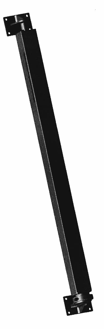
5 Pre-Installation Considerations! Turnstyle Gate Mounting Systems (GMS) are sold in two different mounting configurations, Pillar Mount and Ground Mount. The Pillar Mount utilizes an owner provided post or pillar for its support and is attached to the pillar or post by means of mounting brackets. The Ground Mount operates as a stand alone installation in which the Turnstyle operator is set in the ground. Each system is available in both Manual and Automatic configurations. " If your gate(s) are to be integrated (welded to a Turnstyle Operator,) you or your gate fabricator will need to take special precautions. The inner tube containing the motor and other heat sensitive components must be removed prior to and welding. Failure to take these precautions could result in heat damage to the motor and other internal parts of your operator and render your warranty void. A separate instruction guide regarding welding and powder coating is provided with operators intended for integration. Ground Mount! Pillar Mount Tools / Items required for installation: Turnstyle Pillar Mount GMS : Included with your package: * (1) Turnstyle Pillar Mount operator; (2) for dual gate installation * (2) Pillar Mount brackets; (4) for dual gate installation * (2) Gate mounting brackets; (4) for dual gate installation (if your gate is integrated with the Turnstyle operator, you do not need gate mounting brackets * Gate Mounting Hardware * (1) Turnstyle Installation DVD For Automatic GMS * (1) Control box with control board and two key chain remotes * (1) Rechargeable 12V 7AH Battery, (2) for dual gate installation * (1) AC/AC Transformer * (2) Safety Placards Other items required: * Mounting hardware for your pillar mount brackets (dependent on the material type of your pillar/post) * Power Drill * Drill bit (dependent on the material type of your pillar/ post and pillar mounting hardware) * Hex Bit Socket Set * Tape measure * Level * String level and string (for dual gate installations) Turnstyle Ground Mount GMS : Included with your package: * (1) Turnstyle Ground Mount operator; (2) for dual gate installation * (2) Ground Mount brackets; (4) for dual gate installation * (2) Gate mounting brackets; (4) for dual gate installation (if your gate is integrated with the Turnstyle operator, you do not need gate mounting brackets * Gate Mounting Hardware * (1) Turnstyle Installation DVD For Automatic GMS * (1) Control box with control board and two key chain remotes * (1) Rechargeable 12V 7AH Battery, (2) for dual gate installation * (1) AC/AC Transformer * (2) Safety Placards Other items required: * Shovel or Post Hole digger * Tape measure * Concrete mix * Hex Bit Socket Set * Level * String level and string (for dual gate installations) Foreign & Domestic Patents Issued & Pending!


6 Turnstyle Pillar Mount GMS utilizing Gate Mounting Brackets Integrated Turnstyle Pillar Mount GMS Foreign & Domestic Patents Issued & Pending!


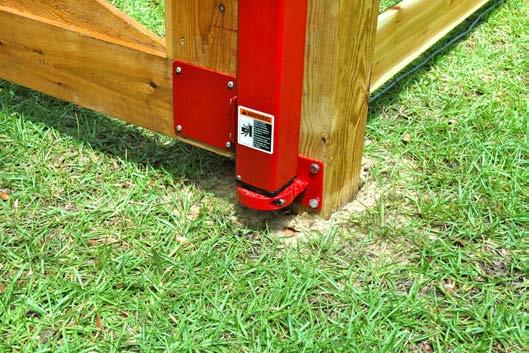
7 Step By Step: How to Install a Turnstyle Pillar Mount Gate Mounting System (GMS) The following instructions are for installation of a Turnstyle Pillar Mount GMS onto typical wood post(s) upon level to near level ground. If your gates will be mounted over ground where interference between the bottom of the gate and the ground could occur when the gate is operated, see your gate fabricator and installer for correct gate fabrication and location of the GMS. Step 1: Mount the Lower Pillar Mount Bracket a. Determine location of lower bracket a. Determine the desired height of the bottom of your gate above ground level and place your lower pillar mount bracket onto the pillar/post accordingly. b. b. Level lower pillar mount bracket If dual gate system is being installed, start your installation with the pillar/post located on the highest ground. Once the desired location of the lower pillar mount bracket is determined, make sure the bracket is level/square onto the pillar/post by using a level and/or square. c. c. Mark pilot holes onto pillar/post for lower pillar mount bracket Once the lower bracket is level, mark all 4 pilot holes onto the pillar/post using the lower pillar mount bracket as your guide. d. Mounting your lower pillar mount bracket onto pillar/post Depending on the construction of your pillar/post, drill your pilot holes and securely attach the lower pillar mount bracket. Make sure the bracket is securely attached to the pillar/post to ensure that it safely carries the weight load anticipated with your particular gate installation. d. Make sure you use a drill bit that corresponds with the material of the pillar/post into which you will be drilling. Step 2: Mounting your Turnstyle Operator a. Place Turnstyle operator into the lower bracket Loosen or remove the collar clamp from the lower bracket using a 5/16 hex wrench to increase ease of placing the inner tube into the lower bracket. Now place the inner round steel tube extending from the bottom of the Turnstyle gate operator into the lower pillar mount bracket and hold the operator upright/parallel to the pillar/post. If you are installing an automatic Turnstyle operator, make sure to not pinch the electrical wire between the operator tube and the lower bracket. a. Foreign & Domestic Patents Issued & Pending!


. c. Level upper pillar mount bracket b. & c.")


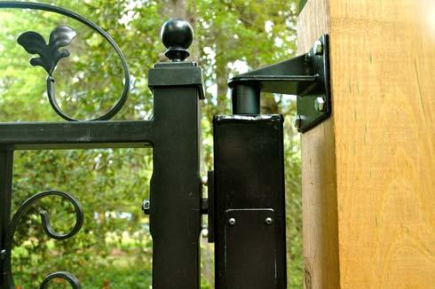
8 Step 3: Mount upper pillar mount bracket For safety purposes, have a helper hold the Turnstyle operator in place while you mount the upper pillar mount bracket. a. Place upper pillar mount bracket onto top of Turnstyle operator Securely place the upper pillar mount bracket onto the pivot detail (top pin) of the Turnstyle operator and hold the upper bracket against the pillar/post. a. The upper pillar mount bracket should touch the white nylon C clip washer located on the top pin of the Turnstyle operator. b. Determine location of upper pillar mount bracket With the upper pillar mount bracket held against the pillar/post, place a level on the Turnstyle operator and move the upper bracket along the pillar/post until the operator is vertically level (plumb). c. Level upper pillar mount bracket b. & c. Once the correct location of the upper bracket is determined, make sure the bracket is level/square onto the pillar/post by using a level and/or square. d. Mark pilot holes onto pillar/post for upper pillar mount bracket Once the upper bracket is level, mark all 4 pilot holes onto the pillar/post using the upper pillar mount bracket as your guide. e. Mounting your upper pillar mount bracket onto pillar/post d. Depending on the construction of your pillar/post, drill your pilot holes and securely attach the upper pillar mount bracket. Make sure the bracket is securely attached to the pillar/post to ensure that it safely carries the weight load anticipated with your particular gate installation. a. Optional: The holes can be drilled directly into the pillar/post through the holes of the upper bracket without removing the upper brackets. Be sure to hold the upper bracket steady so the holes will be drilled into the correct location. b. Make sure you use a drill bit that corresponds with the material of the pillar/post into which you will be drilling. e. Step 4: Attach the gate mounting brackets and gate onto the Turnstyle Operator. If your gate has been integrated with your Turnstyle operator, you will not need to attach gate mounting brackets. In this case, your gate will already be integrated (welded) with the Turnstyle operator. See page 4 for further instructions. See page 12 for instructions on attaching your brackets and gate to your Turnstyle operator. At this point you have successfully installed a Pillar Mount single gate manual Turnstyle GMS Foreign & Domestic Patents Issued & Pending!


9 Step By Step: How to Install the opposite operator for a Turnstyle Pillar Mount Dual Gate Mounting System (GMS) Step 1: Mount lower pillar mount bracket onto opposite pillar/post. a. Determine location of lower bracket onto adjacent pillar/post. Using a string level, stretch a string from the bottom edge of the previously installed lower bracket to the opposite pillar/post. Once the string is level, mark the opposite pillar/post. Place the bottom edge of the second lower pillar mount bracket onto the opposite mark on the pillar/post. Once the correct location of the opposite lower pillar mount bracket is determined, return to page 7 and follow installation instructions from Step 1: b. Level lower pillar mount bracket. When mounting dual gates onto pre-existing columns or posts which are not perfectly plumb, adjustable brackets may be used. See page 13. Leave the adjustment collar on the lower bracket loose for manual operation. At this point you have successfully installed a Pillar Mount dual gate manual Turnstyle GMS If you are installing an automatic Turnstyle GMS, proceed to page 14 to find the electronics installations instructions. Foreign & Domestic Patents Issued & Pending!

 should be placed at least!")


 on at least 2 consecutive sides of the operator and on top as you are filling the hole around the ground sleeve with concrete.")
10 Step By Step: How to install a Ground Mount GMS The following instructions are for installation of a Turnstyle Ground Mount GMS upon level to near level ground. If your gates will be mounted over ground where interference between the bottom of the gate and the ground could occur when the gate is operated, see your gate fabricator and installer for correct gate fabrication and location of the GMS. Turnstyle Ground Mount Operator!!! Ground Sleeve Step 1: Install ground sleeve and Turnstyle Ground mount operator a. Determine location of your Turnstyle Ground mount GMS a. Your Turnstyle ground mount operator (if installed in an end mount configuration) should be placed at least! away from the last fence post of your fence section to avoid the operator hitting the fence post during operation. a. & b. b. Prepare hole in the ground for your Ground Mount operator Once the desired location of the ground mount operator is determined, dig a hole in the ground approximately 31 deep and approximately 10 in diameter with a shovel or post hole digger. Test fit the ground sleeve into the hole and continue digging until the collar clamp on the ground sleeve is just above ground level. c. Prepare concrete b. If a dual gate system is being installed, start the installation of your first ground mount operator next to the end of your fence section located on the highest ground elevation. Prepare concrete mixture according to manufacturer s instructions. d. Level Turnstyle operator and secure ground sleeve into ground Once the appropriate size hole has been prepared with the ground sleeve in place, slide the inner steel tube of the Turnstyle operator into the ground sleeve. Tighten the collar clamp located at the top of the ground sleeve onto the inner steel tube. With ground sleeve in hole and operator attached, recheck the placement of your operator to be sure the operator is the desired distance from the end of your fence or last fence post. Adjust as necessary. d. Once the operator and ground sleeve are in the desired position, place a level on the side of the Turnstyle operator and fill the hole around the ground sleeve with concrete. Continuously check your level (plumb) on at least 2 consecutive sides of the operator and on top as you are filling the hole around the ground sleeve with concrete. Adjust the operator as needed through out this process to be sure the operator is plumb once the hole is completely filled with concrete. Although concrete is recommended around the ground sleeve, concrete is not absolutely necessary if your gate is to be mounted onto the Turnstyle ground mount operator in a center mount configuration. When a gate is mounted in a center configuration, the weight of the gate is equally balanced on either side and does not necessarily need the additional support that is required for an end mount configuration. Adding some gravel around the ground sleeve can help in soft soil conditions. Foreign & Domestic Patents Issued & Pending!

 is/are secure, replace the Turnstyle operator(s) into the ground sleeve(s) if they were removed during concrete curing.")
 with the Turnstyle operator. See page 5 for further instructions.")

 Step 1: Install the opposite ground sleeve and Turnstyle ground mount operator Return")
11 e. Allow concrete to cure Support the Turnstyle operator if necessary, until the concrete sets sufficiently to hold the operator and ground sleeve plumb or loosen the collar clamp on the ground sleeve and slide the inner steel tube of the operator out of the ground sleeve and allow the concrete to cure. a. Removing the Turnstyle operator from the ground sleeve while allowing the concrete to cure will reduce external forces on the ground sleeve. b. Cover the ground sleeve while allowing the concrete to cure to avoid debris from entering the ground sleeve. c. Allow the concrete to cure according to the concrete manufacturer s guidelines. d. Leave the collar clamp on the ground sleeve loose for manual operation. Once concrete is set and ground sleeve(s) is/are secure, replace the Turnstyle operator(s) into the ground sleeve(s) if they were removed during concrete curing. Step 2: Attach the gate mounting brackets and gate onto the Turnstyle Operator. If your gate has been integrated with your Turnstyle operator, you will not need to attach gate mounting brackets. In this case, your gate will already be integrated (welded) with the Turnstyle operator. See page 5 for further instructions. See page 12 for instructions on attaching your brackets and gate to your Turnstyle operator. At this point you have successfully installed a Ground Mount single gate manual Turnstyle GMS If you are installing an automatic Turnstyle GMS, proceed to page 14 to find the electronics installations instructions. Step By Step: How to Install the opposite operator for a Turnstyle Ground Mount Dual Gate Mounting System (GMS) Step 1: Install the opposite ground sleeve and Turnstyle ground mount operator Return to page 10 and follow Ground Mount installation instructions from Step 1: a. Determine location of your Turnstyle Ground mount GMS through Step 1: c. Prepare concrete and then proceed below. a. Using a string level, stretch a string from the top of the previously installed ground sleeve to the top of the opposite ground sleeve. Adjust the ground sleeve as needed (back filling if necessary,) until the string is level and the ground sleeve is in its desired location. Return to page 10 and follow Ground Mount installation instructions from Step 1: d. Level Turnstyle operator and secure ground sleeve into ground through Step 2: Attach the gate mounting brackets and gate onto the Turnstyle Operator. At this point you have successfully installed a Ground Mount dual gate manual Turnstyle GMS If you are installing an automatic Turnstyle GMS, proceed to page 14 to find the electronics installations instructions. Foreign & Domestic Patents Issued & Pending!

 have been integrated (welded) with your Turnstyle operator, you will not need to attach gate")


 which provide a measurement adjustment")

12 Step By Step: How to attach your gate mounting brackets and gate onto your Turnstyle operator(s) Three types of gate mounting brackets are available: Unicorn brackets, wood brackets and tube brackets. Please follow the instructions that correspond to your gate mounting brackets. *Note - If your gate(s) have been integrated (welded) with your Turnstyle operator, you will not need to attach gate mounting brackets. a. Attach gate mounting brackets Line up the 4 holes in the gate mounting brackets with the 4 pre-drilled holes in the Turnstyle operator. Insert the provided screws through the holes in the gate mounting brackets into each of the 4 pre-drilled holes in the Turnstyle operator. Tighten these screws with a 3/16 hex wrench. b. Mount your gate onto the gate mounting brackets It is suggested for safety purposes that two people be present while mounting any gate(s) onto the Turnstyle mounting brackets. Unicorn Brackets Mount your gate onto the Turnstyle operator by sliding the unicorn bracket into the holes on the side of your gate. Once your gate is in place upon both the top and bottom unicorn brackets, place a washer and nut over remaining exposed portion of the unicorn bracket. Tighten nut with the provided hex wrench. * Note - Unicorn brackets have two nuts (one on either side of the gate frame) which provide a measurement adjustment feature by tightening and/or loosening the nuts in order to prevent gaps between your dual gates and/or opposite post. Unicorn Brackets Tube Brackets Set mounting end of tube gate into the cup of the tube gate mounting brackets Adjust your gate to the desired position along the Turnstyle gate operator. Once your gate is in the desired position, alternately tighten the two socket head cap screws in the tube gate mounting brackets to secure your gate onto the Turnstyle gate operator. Lastly, lock the position of your tube gate in the mounting brackets by tightening the set screw in the outer half of the tube gate mounting bracket. Do not tighten bolts until your tube/chain link gate is in the desired position along the Turnstyle gate operator. Tube Brackets Foreign & Domestic Patents Issued & Pending!


13 Wood Brackets Slide wood gate into the wood gate mounting brackets Adjust wood gate vertically to the desired position along the Turnstyle operator. Place a level on top of the wood gate and adjust gate as needed. Once the gate is level and in the desired position along the Turnstyle operator, mark all four holes on each side of the wood brackets. *Optional - The holes can be drilled directly into the wood gate through the holes of the wood brackets without removing the wood gate from the wood gate mounting brackets. Be sure to hold the wood gate steady so the holds will be drilled into the correct location. Slide wood gate back into the wood brackets (if needed) and line up the holes in both sides of the wood brackets with the pre-drilled holes in the wood gate. Screw through the holes in the wood brackets into each of the pre-drilled holes in the wood gate and tighten to secure your wood gate onto the Turnstyle gate operator. Thru bolts can also be used. Wood Brackets Top Bracket Adjustable Pillar Mount Brackets Our optional adjustable pillar mount brackets have a 1 1/2 Adjustable horizontal Pillar range of Mount movement, Brackets making gate adjustments quick and easy. See the Our Turnstyle optional Catalog adjustable for details pillar and mount pricing brackets have information. a 1 1/2 horizontal range of movement, making gate adjustments quick and easy. Bottom Bracket See the Turnstyle Catalog for details and pricing information. Foreign & Domestic Patents Issued & Pending!
 switch, and the 100dB Alarm.")


: a.")
 c.")

14 Step By Step: Control Panel Installation for your GMS The Control Panel will arrive mounted inside the Control Box. Also mounted inside the Control Box, and pre-wired to the control panel; are the wireless receiver with its antenna, on-off (reset) switch, and the 100dB Alarm. The Control Box is configured to accommodate wiring. Each operator is supplied with approximately 20 feet of low-voltage wire, allowing the Control Box to be mounted on any surface within a 20 foot radius. The Control Box also houses the 12 Volt battery(s). An on-off (reset) switch is located on the underside of the Control Box. It is also pre-wired to the appropriate terminal on the Control Panel. 1. Control Panel: The Control Panel is a printed circuit board measuring 8.5 inches by 3.5 inches. WARNING: Do not attempt to remove the Control Panel from the Control Box. Contact with the reverse side of the printed circuit board can cause irreparable damage to the circuit board and render your warranty void. The installer and/or end user has four areas of concern when wiring the Control Board (see descriptions and figures below): a. Dip Switches (a small red block containing six dip switches, located on the top left side of the Control Board) b. Sensitivity Adjustment Potentiometers (small round white controls with adjusting screw heads, located in the upper right quadrants of the Control Board) c. Fuses (located on bottom left side of Control Board) 15 amp limit. d. Wiring Terminals (There are 18 sets of wiring blocks located along the bottom of the Control Board) a. b. b. c. d. a.!!!! b.!!! c. e. Digi-Code Wireless Receiver The Digi-Code Wireless Receiver comes pre-wired to the Turnstyle Control Board and contains a small red square containing 10 dip switches (figure e.) These dip switches are used to program a wireless keychain transmitter, or a wireless visor transmitter (figures f.) to the Turnstyle system. The wireless transmitters also contain 10 dip switches. Simply unscrew the back of your transmitter and sync the dip switches to match the dip switches on the Wireless Receiver Board. Dip switch synchronization is critical to proper programming. Example: if switch 1 is dipped towards the number on the wireless receiver board, it must also be dipped towards the number inside the wireless transmitter as well, and so on. Figure g. shows the dip switches contained inside the wireless keychain transmitters, the same toward the number programming technique is required. *Note: Factory set dip switches will be in an alternating pattern (2,4,6,8,10), and creating a unique combination is highly recommended. g. f. Foreign & Domestic Patents Issued & Pending!
15 d. 2.Wiring Terminal Functions: The 18 sets of wiring blocks are labeled in white lettering. The function of each wiring block is described below: Spare 12V - These three printed circuit board (PCB) terminals provide access points for 12VDC power that may be required to power peripheral accessories and/or safety devices. If none of these devices are included in your final installation, these terminals will remain unused. CAUTION - Do NOT connect ANY voltage source to any of these terminals. Doing so will damage the circuit board and render your warranty void. Solar/AC - Input for Solar Panel or supplied AC power supply. The polarity of the inputs is non critical. The recommended voltage is either 12VAC or 1 amp. *DO NOT USE CONVENTIONAL 110V. BATTERY - Input for battery source. This DC voltage requires correct polarity. However, reverse polarity will not damage the control panel. The positive (Red) wire should always be connected to the left-hand terminal marked (+) and the negative (Black) wire connected to the right-hand terminal marked (-). SWITCH - System power switch. This input is used to power off / on and to reset the system. Upon power up, all previous states are reset and the system will always initialize to gate being fully closed and locked. CSF (Contact Strip Front of Gate) - Input for contact safety edge installed on front of gate. Activated input will prevent gate from closing, and reverse the gate direction if gate was closing. CSB (Contact Strip Back of Gate) - Input for contact safety edge installed on back of gate. Activated input will prevent gate from opening, and reverse the gate direction if gate was closing. EMER. VEH. (Emergency Vehicle Opener) - Input for Emergency Vehicle Opener. Activation will open the gate. Continuous activation will prevent the gate from automatically closing. EXIT DET. (Exit Detection) - Input for devices to be used to only open the gate. Activated input will start the gate opening procedure if gate was not moving. Input activations while gate is moving have no effect. KEYPAD - Input for wired keypad, or other fixed input device in sight of gate. Activation will Open/Stop/Close/Stop the gate (repeated activations cycle through these 4). Activation will not stop the alarm. STOP/NCI (NON-CONTACTING INPUT) - Input for non-contacting safety sensors, such as an optical sensor, with a normally open output. Activated input will stop gate instantly and return gate to fully open position. ALARM - Output for 12VDC high volume (100 db minimum) alarm (included). If alarm is activated, clicking the on/off switch will silence the alarm and reset the system. LIGHT - Output for 12V lighting. Lights turn on when gate is moving and remain on for approximately 30 seconds after completion of the cycle. Do not exceed 40W of lighting. LOCK - Terminal points for lock motor(s) leads. Multiple locks may be employed. MAG LOCK - Terminal points for magnetic lock leads. The Magnetic Lock activates as soon as the gates complete their close cycle. The gate opening cycle will not begin until the Magnetic Lock disengages. The Magnetic Lock is wired into the terminal labeled Mag Lock Polarity Mag locks is are not polarity crucial. sensitive. Switches Switches 5 and 6 5 must and be 6 must open. be open. GATE 1 - Terminal points for gate motor leads. Polarity depends on desired swing of gate. Use this terminal with a single mount gate. GATE 2 - Terminal points for gate motor leads. Polarity depends on swing of gate. Use this terminal in addition to Gate 1 with dual mount gates. Foreign & Domestic Patents Issued & Pending!


 to the Solar/AC terminal.")

16 3. Wiring Instructions *NEVER CONNECT 110V AC DIRECTLY TO THE CONTROL BOARD. The Turnstyle System is low voltage (12V DC), thereby eliminating the danger of electric shock. Care should be taken however to guard against cuts and abrasions of the wire as this could cause a short circuit. All wires should be passed through one of the strain relief fittings in the bottom of the Control Box. Wires should be stripped back between 1/4 if needed. The exposed ends are then inserted into the proper terminals in the wiring blocks and the screws tightened. a. Attach the Gate wires first. If a single gate is installed, attach the wires to Gate 1 terminal (Blue wire on left, Brown wire on right), keeping in mind you may have to reverse polarity. If dual gates are installed, attach the wires from either gate to Gate 1 terminal and the other to gate 2 terminal. b. Next, attach the charging source(s) to the Solar/AC terminal. These terminals are not polar. You can attach an optional 12V solar panel or the included AC/AC wall transformer, an AC trickle charger, or both to the Solar/AC terminals. These sources charge the 12 volt battery. c. Next, attach the 12V battery, paying close attention to wiring colors. *Note: Before wiring other accessories, you should now proceed to the Adjustments section below to adjust the swing of the gates, polarity and sensitivity. 4. Adjustments Now that you have installed and wired your gate(s), you must now make some adjustments; the opening and closing positions of the gate(s), the sensitivity of the gate(s) to obstructions, and Automatic Closing (Auto-Close) time (if desired). 1. Open and Closed Positions of the Gates Turnstyle Gate Operators are engineered to move 90 degrees in either direction. Following your installation, your gates will most likely not open and close the way you want. However, adjustment to the desired positioning is very simple. First, direct your attention to the collar at the bottom of the operator(s). On a pillar mount the collar is a part of the lower mounting bracket. on a ground mount, the collar is a part of the ground sleeve (pictured below). The collar has two Allen (hex head) screws. Position the gate(s) in the closed position. Tighten the Bottom Mount screws so that the gate(s) are level and will not swing freely. a. With your keychain transmitter, press the button to activate the gate(s). Note the direction of opening of each gate. Press the button a second time to stop the gates before they hit any obstructions. If a gate is not moving in the desired direction, reverse the wires for that gate on the Control Panel wiring block. Again, press the transmitter button and allow the gate(s) to move until they completely stop. The gate(s) will not be in the desired positions. Do not press the button again because that will reverse the movement of the gate(s). b. Loosen the collars at the bottom of the gate(s) until the gates move freely. Position the gate(s) in the full 90 degree open position. Tighten the collars. Press the transmitter button again and allow the gate(s) to fully close. Loosen the collars and adjust the gate(s) to the final closed position. Tighten the collars securely. The gate(s) should now open and close to the desired positions. If the gate positions need any fine tuning, use the above procedure. 2. Sensitivity Adjustment The sensitivity adjustments are round white potentiometers located in the upper right quadrant of the circuit board (pictured right). The sensitivity is preset at the factory for most applications. It is intended to interrupt the operation of the system in the event the gate(s) encounter resistance such as striking an object or person. However, because of wind load or the weight of the gate(s), you may need to adjust sensitivity. To decrease sensitivity, turn the adjusting screw counter-clockwise. To increase sensitivity, turn the adjusting screw clockwise. Foreign & Domestic Patents Issued & Pending!
 without the need of human input.")
17 3. Locks & Auto-Close Adjustments The Turnstyle operator system has an automatic closing (Auto-Close) feature that is programmed into the Control Panel. This feature allows you to have the Control Panel automatically close your gate(s) without the need of human input. You can elect to have the gate(s) close after either 5, 10, 20, 30, 40, 50, or 60 seconds. The Auto-Close time begins as soon as the gate(s) reach their fully open positions. Auto-Close may be modified, enabled or disabled at any time. On the left hand side of the control panel is a small red block with six switches (pictured below, left). Switches 1, 2 & 3 select Auto-Close. See chart below. Switch 4: MOTOR-DRIVE MODE. Closing (Up) Switch 4 will select simultaneous motor drive mode (Both Gates 1 and 2 will open and close at the same time), while opening (Down) Switch 4 will select sequential motor drive mode (Gate 1 will open first, followed in 1 second by Gate 2; Gate 2 will close first, followed by Gate 1). Always select simultaneous mode when using the Power Bolt Lock and sequential mode when using the Magnetic Lock. Switch 5: LOCK TYPE. Closing (Up) switch 5 will select the Power Bolt Lock, while opening (Down) Switch 5 will select the Magnetic Lock. Switch 6: LOCK ENABLE. Closing (Up) switch 6 will disable the Power Bolt Lock. Opening (Down) Switch 6 will enable the Power Bolt Lock or Magnetic Lock as selected. Switch 1 Switch 2 Switch 3 CLOSED Auto-Close Adjustments (Switches 1-3) SWITCH 1 SWITCH 2 SWITCH 3 FUNCTION CLOSED (UP) CLOSED (UP) CLOSED (UP) AUTO-CLOSE DISABLED CLOSED (UP) CLOSED (UP) OPEN (DOWN) AUTO CLOSE ENABLED - 5 SECOND DELAY OPEN CLOSED (UP) OPEN (DOWN) CLOSED (UP) AUTO CLOSE ENABLED - 10 SECOND DELAY CLOSED (UP) OPEN (DOWN) OPEN (DOWN) AUTO CLOSE ENABLED - 20 SECOND DELAY Switch 4 Switch 5 Switch 6 OPEN (DOWN) CLOSED (UP) CLOSED (UP) AUTO CLOSE ENABLED - 30 SECOND DELAY OPEN (DOWN) CLOSED (UP) OPEN (DOWN) AUTO CLOSE ENABLED - 40 SECOND DELAY *Note: In the figure above, Switches 1-4 are in the Closed (Up) position; Switched 5-6 are in the Open (Down) position. Tip* Closed is towards the number. OPEN (DOWN) OPEN (DOWN) CLOSED (UP) AUTO CLOSE ENABLED - 50 SECOND DELAY OPEN (DOWN) OPEN (DOWN) OPEN (DOWN) AUTO CLOSE ENABLED - 60 SECOND DELAY *Note: If, after enabling the Auto-Close feature; you find the gates are automatically opening rather than closing, the polarity of the gate wires are reversed at the control panel. Simply reverse the positions of the wires at the Gate terminals. Now, after your gates open, they should Auto-Close. Motor Drive Mode (Switch 4) Lock Type (Switch 5) Lock Enable (Switch 6) SWITCH 4 FUNCTION SWITCH 5 FUNCTION SWITCH 6 FUNCTION CLOSED (UP) SIMULTANEOUS MOTOR DRIVE MODE CLOSED (UP) POWER BOLT LOCK SELECTED CLOSED (UP) LOCK MOTOR DISABLED OPEN (DOWN) SEQUENTIAL MOTOR DRIVE MODE OPEN (DOWN) MAGNETIC LOCK SELECTED OPEN (DOWN) POWER BOLT OR MAGNETIC LOCK ENABLED Foreign & Domestic Patents Issued & Pending!


18 Optional Equipment Installation The control panel to your Turnstyle Gate Operating System allows the employment of various optional devices. 1. Solar Panel - A solar panel is an optional battery charging device. The solar panel wires are connected to the terminal block labeled Solar/AC. Polarity is not critical. Be sure the solar panel is facing south for maximum exposure to sunlight. 2. Exit Devices - Various exit devices can be used to open your gate(s) upon exit. These include exit wands, loop detectors and optical sensors. These devices should be wired into the terminal labeled ED. Wiring instructions are provided with each of these devices. 3. Lights (low voltage) - Low voltage lights add beauty as well as function. They are wired directly into the terminal block labeled Light. The lights come on when the gate is activated and remain on for approximately 30 seconds after the cycle completes. They also visually relay critical system information such as battery conditions and sensor actions. 4. Contact Sensors - Contact sensors are sensitive strips attached to either the front, back, or both edges of the opening end of a gate. Contact sensors will stop the movement of a gate immediately upon contacting an object or person. A front edge contact sensor must be connected to the CSF terminal and back edge contact sensor must be connected to the CSB terminal. 5. Power Lock - The power bolt lock is designed to close four (4) seconds after the gate(s) complete their close cycle. The gate opening cycle will not begin until the power bolt lock is completely open. The power bolt lock is wired into the terminal labeled LOCK. Polarity is critical. Before mounting your lock to your gates, follow the below sequence to ensure proper installation and functioning. a. First establish that your gates are opening and closing correctly. (See Adjustments, p.16). If you are employing the Auto-close feature, follow the Auto-close Adjustment instruction on p. 17. b. Extend the bolt on your lock by touching the wires to the battery terminals (Brown wire to the Positive RED Terminal, Blue wire to the Negative BLACK Terminal). With the gates in the closed position, wire the lock to the control panel at the terminal marked LOCK and lay it on the ground. Now, open your gates and close them. The lock bolt should retract when the gates are opened and extend 4 seconds after the gates are fully closed. c. If the lock works in reverse of the open/close cycle, simply reverse the wires on the board to change the polarity. Once the lock opens and closes in sync with the gate(s) it is safe to mount your lock; (See p. 17). 6. Key Pads - The wireless key pad is designed to work with the wireless receiver, already installed in your control box electronics enclosure. Follow the instructions provided with the wireless keypad for programming. No further wiring is required. Hard wired key pads should be connected to the terminal marked K on the control panel. Refer to the instructions provided with the wired keypad for programming. 7. Emergency Vehicle Opening Devices - The EVO terminal on the control panel is reserved for emergency vehicle opening devices for admittance of fire and other emergency vehicles. Check with local fire, police and municipal authorities for EVO requirements. Foreign & Domestic Patents Issued & Pending!
. AUDIBLE ALARM SOUNDING.")
19 TROUBLESHOOTING THE OPERATOR AND ACCESSORIES SYMPTOM THE GATE OPENS OK BUT AFTER CLOSING, IT REOPENS. THE GATE MOVES A FEW FEET, BUT THEN STOPS AND/OR REVERSES. THE GATE WILL NOT OPEN USING THE KEYFOB OR KEYPAD TRANSMITTERS. THE KEYFOB TRANSMITTER WORKS ONLY AT A SHORT DISTANCE. ONLY ONE GATE WILL OPERATE (DUAL GATES). AUDIBLE ALARM SOUNDING. THE GATE OPENS BUT THEN CLOSES WITHIN A FEW SECONDS. THE POWER BOLT LOCK WILL NOT OPERATE. THE POWER BOLT LOCK CLOSES WHEN IT SHOULD OPEN AND OPENS WHEN IT SHOULD CLOSE. GATE SQUEAKS WHEN OPENING OR CLOSING. GATE IS OUT OF ALIGNMENT AFTER CLOSING. REMEDIES 1. EXCESSIVE CLOSING PRESSURE. IF THE GATE IS OVER ROTATING INTO A FIXED STOP, LOOSEN BOTTOM COLLAR AND READJUST GATE POSITION. (SEE PAGE 16) 2. THE AUTO-REVERSE SENSITIVITY IS TOO HIGH. READJUST SENSITIVITY. (SEE PAGE 16) 3. POWER BOLT LOCK MAY BE MISALIGNED. ADJUST ACCORDINGLY. 1. THE AUTO-REVERSE SENSITIVITY IS TOO HIGH. READJUST SENSITIVITY. (SEE PAGE 16) 2. BATTERY VOLTAGE MAY BE TOO LOW. MAKE SURE CHARGER AND/OR SOLAR PANEL ARE DELIVERING CURRENT. 1. CHECK SWITCH LOCATED ON BOTTOM OF CONTROL BOX, TO ENSURE IT IS IN THE ON POSITION. 2. CODE SWITCHES IN THE TRANSMITTERS DO NOT MATCH THE CODE SWITCHES IN THE RECEIVER. RESET THE CODE SWITCHES TO MATCH. (SEE KEYCHAIN TRANSMITTER INSTRUCTIONS.) 3. LOW OR DEAD BATTERY IN THE TRANSMITTER. REPLACE BATTERY. 4. FUSE BLOWN ON CIRCUIT BOARD. REPLACE FUSE. IF FUSES CONTINUE TO BLOW, CONTACT TURNSTYLE TECHNICAL SUPPORT ( ). 5. LOOSE WIRE. CHECK FOR LOOSE AND/OR UNATTACHED WIRES. 6. OPERATOR BATTERY LOW VOLTAGE. CHECK TRANSFORMER AND/OR SOLAR PANEL WIRING (PAGE 15). REPLACE BATTERY IF NECESSARY. 7. DEFECTIVE RECEIVER. REPLACE RECEIVER. IF YOU DETERMINE THE SYSTEM CANNOT BE RESTORED IMMEDIATELY, LOOSEN THE BOTTOM COLLAR ON THE OPERATOR, MAKING YOUR GATE MANUAL. 1. TRANSMITTER BATTERY LOW. REPLACE BATTERY. 2. RECEPTION IS BEING BLOCKED. AN EXTERNAL ANTENNA MAY BE NECESSARY. CHECK THE CRCUIT BOARD. IF YOU HAVE DUAL GATES, THERE SHOULD BE TWO WIRES ATTACHED TO THE WIRING TERMINAL MARKED GATE1 AND TWO WIRES ATTACHED TO THE TERMINAL MARKED GATE2. IF NOT, REATTACH THE WIRES. RESET ON/OFF SWITCH. CHECK GATES FOR OBSTRUCTIONS. IF THE ALARM CONTINUES, TURN OFF SWITCH FOR 5 MINUTES AND THEN TURN BACK ON. (THE AUDIBLE ALARM IS A SAFETY DEVICE AND SHOULD NEVER BE DISCONNECTED). THE AUTO-CLOSE FEATURE MAY BE ACTIVATED. SEE PAGE 17 TO DEACTIVATE OR CHANGE THE DELAY TIME ON THE AUTO-CLOSE FEATURE. 1. CHECK THE WIRING. BOTH WIRES FROM THE POWER BOLT LOCK SHOULD BE WIRED INTO THE CIRCUIT BOARD AT TERMINAL LOCK. 2. CHECK THE AUTO-CLOSE SWITCHES ON THE CIRCUIT BOARD. THE LOCK WILL NOT WORK UNLESS SWITCH 1 IS UP. (SEE PAGE 17) THE WIRES ARE INCORRECTLY CONNECTED AT THE CONTROL PANEL. AT THE TERMINAL MARKED LOCK REVERSE THE POSITION OF THE TWO WIRES. TOP PILLAR MOUNTING BRACKET MAY BE MISALIGNED. CHECK THE OPERATOR AND TOP BRACKET FOR PLUMB AND LEVEL. ADJUST IF NECESSARY. (SEE PAGE 8) BOTTOM MOUNTING BRACKET IS NOT TIGHT ENOUGH. REALIGN GATES AND TIGHTEN BOTTOM BRACKET COLLAR SUFFICIENTLY. (SEE PAGE 7) Foreign & Domestic Patents Issued & Pending!


 Operators) from the from date the of date purchase, of purchase, providing providing recommended recommended installation installation procedures procedures are")

20 V 2.1 V. 2.2 Our Promise To You We are dedicated to providing the industry s most reliable and aesthetically pleasing gate opening system. We promise uncompromising quality and innovation backed up by the utmost in friendly and efficient service. By using the finest components coupled with innovative engineering, we strive to make the Turnstyle Gate Mounting System second to none in performance, versatility, safety and aesthetics. Warranty TURNSTYLE AUTOMATIC GATE OPERATOR TURNSTYLE ENTERPRISES, INC. LIMITED WARRANTY " Turnstyle Turnstyle Automatic Automatic Gate Gate Operating Systems are are warranted against defects for a period of of (12) (12) twelve months months (thirtysix (36) for months Commercial for Commercial Operators) Operators) from the from date the of date purchase, of purchase, providing providing recommended recommended installation installation procedures procedures are are followed. This (thirty-six (36) months followed. This warranty is in lieu of all other warranties expressed or implied (some states do not allow limitations on how long warranty is in lieu of all other warranties expressed or implied (some states do not allow limitations on how long an implied warranty an implied warranty lasts, so this limitation may not apply to you) and shall be considered void if damage was due to improper lasts, installation so this limitation or use, connection may not apply to improper to you) power and shall source, be considered or if damage void was caused if damage by fire, was flood due or to lightning. improper The installation manufacturer or use, connection will not to be improper responsible power for any source, labor or charges if damage incurred was in caused the removal by fire, or replacement flood or lightning. of defective The manufacturer parts. will not be responsible for any labor charges incurred in the removal or replacement of defective parts.! In case of failure due to defective material or workmanship during the warranty period, the defective part will be repaired or replaced at the manufacturer s option at no charge if returned freight prepaid. New or factory rebuilt replacements may In be case used. of Replacement failure due to parts defective are warranted material or for workmanship the remaining during portion the of the warranty original period, warranty the period. defective The part manufacturer will be repaired or replaced will pay at the standard manufacturer s ground freight option on the at no return charge of repaired if returned or replaced freight items prepaid. in warranty. New or factory rebuilt replacements may be used. Replacement parts are warranted for the remaining portion of the original warranty period. The manufacturer will pay standard ground freight on the return of repaired or replaced items in warranty; other forms of shipping may be utilized at the expense of the customer. SIMPLY REVOLUTIONARY Toll Free: Direct: Return Policy TURNSTYLE ENTERPRISES, INC. Place Copy of Identification ALL PRODUCTS Label Here Turnstyle Enterprises, inc. will accept returned or exchanged products in original packaging for any reason within 30 days after purchase, except in instances where product has been damaged due to improper installation or installs which do not comply with Turnstyle s installation specifications, which render all warranties void. We credit (on exchanges) or refund (on returns) the cost of the products! only, This not label shipping contains charges. valuable We also information. implement a 15% restocking Please charge use the on serial all returned number products. whenever The customer communicating is responsible with Turnstyle for the shipment Customer cost Service. of the replacement Identical (exchange) labels are product(s). affixed to Please the Turnstyle call or contact post and us before to the returning inside cover a product. of the control panel enclosure. Foreign & Domestic Patents Issued & Pending!
Eagle Access Control Systems, Inc. / (800) / (3)
 / (3)") UL Listings IMPORTANT SAFETY INSTRUCTIONS A. WARNING To reduce the risk of injury or death: 1) READ AND FOLLOW ALL INSTRUCTIONS. 2) Never let children operate or play with gate controls. Keep the remote
UL Listings IMPORTANT SAFETY INSTRUCTIONS A. WARNING To reduce the risk of injury or death: 1) READ AND FOLLOW ALL INSTRUCTIONS. 2) Never let children operate or play with gate controls. Keep the remote
INSTALLATION M ANUAL
 INSTALLATION MANUAL Table of Contents UL Listings Installing the Warning Sign / Precautions Methods of Installation / Compact Installation Mounting the Secondary Entrapment / Welding Gate Arn Mounting
HYPPOETL HYPPO DUALETL 12 VOLT DC Swing Gate Operator
 HYPPOETL HYPPO DUALETL 12 VOLT DC Swing Gate Operator Manufactured by NICE SpA INSTALLATION MANUAL 08/10 CONTENTS IMPORTANT SAFETY INSTRUCTIONS... 3 Applications...... 4 Pre-Installation Checklist... 5
APOLLO Gate Operators, Inc.
 APOLLO Gate Operators, Inc. Model BA12 12 VOLT DC BARRIER ARM OPERATOR INSTALLATION MANUAL 0707 CONTENTS IMPORTANT SAFETY INSTRUCTIONS... 3 Applications... 4 Pre-Installation Checklist... 5 Operator Installation...
Gate Operators, Inc. Model 7100UL Residential & Medium Duty Commercial Slide Gate Operator INSTALLATION MANUAL
 Gate Operators, Inc. Model 7100UL Residential & Medium Duty Commercial Slide Gate Operator INSTALLATION MANUAL 10-04-00 CONTENTS Safety Precautions... 2 Applications... 3 Pre-Installation Checklist...
ontrol Systems, Inc. Swing Gate Installation Manual Eagle-200 Series Eagle-100 Series UL325 and UL991 Compliant
 Swing Gate Installation Manual Eagle-200 Series Eagle-100 Series ontrol Systems, Inc. www.eagleoperators.com Operator installation and instructions for the Eagle-200 and Eagle-100 Series. UL325 and UL991
FOR CLASS I, II, III, IV VEHICULAR GATE OPERATORS
 Ramset_Man300.qxd 4/18/05 1:06 PM Page 1 FOR CLASS I, II, III, IV VEHICULAR GATE OPERATORS Ramset_Man300.qxd 4/18/05 1:06 PM Page 2 www.ramsetinc.com Ramset_Man300.qxd 4/18/05 1:06 PM Page 3 TABLE OF CONTENTS
Model 1550 Single Swing Gate Model 1650 Dual Swing Gate
 Gate Operators, Inc. Model 1550 Single Swing Gate Model 1650 Dual Swing Gate Swing Gate Operator CONTENTS Safety Precautions... 2 Applications... 3 Pre-Installation Checklist... 4 Parts Identification...
RAMSET
 RAMSET TABLE OF CONTENTS Important Safety Requirements & Instructions...1 Responsibilities of Installers and Technicians...2 Important Safety Requirements by UL Standards...3 Classes of Vehicular Gate
COMMERCIAL 24VDC HIGH TRAFFIC OVERHEAD DOOR AND GATE OPERATOR WITH BATTERY BACKUP INSTALLATION MANUAL
 COMMERCIAL 24VDC HIGH TRAFFIC OVERHEAD DOOR AND GATE OPERATOR WITH BATTERY BACKUP INSTALLATION MANUAL Model HCTDCU HCTDCU Motor Unit HCT08 8 Foot Rail HCT10 10 Foot Rail HCT12 12 Foot Rail THIS PRODUCT
Sliding Gate Opener User s Manual
 Gat Model: Sliding Gate Opener User s Manual GA2500 Gate1Access, LLC. www.gate1access.com Email: support@gate1access.com 1 Thank you for purchasing GA2500 gear rack drive sliding gate opener. We are sure
RAMSET RAM
 www.ramsetinc.com TABLE OF CONTENTS Important Safety Requirements & Instructions...1 Responsibilities of Installers and Technicians...2 Important Safety Requirements by UL Standards...3 Classes of Vehicular
FOR CLASS I, II, III, IV VEHICULAR GATE OPERATORS
 R_Ramset_Ram3000.qxd 8/19/05 4:56 PM Page 1 FOR CLASS I, II, III, IV VEHICULAR GATE OPERATORS R_Ramset_Ram3000.qxd 8/19/05 4:56 PM Page 2 www.ramsetinc.com R_Ramset_Ram3000.qxd 8/19/05 4:56 PM Page 3 TABLE
APOLLO Gate Operators, Inc.
 APOLLO Gate Operators, Inc. Model 3500ETL/3600ETL Commercial Swing Gate Operator INSTALLATION MANUAL 01/08 CONTENTS IMPORTANT SAFETY INSTRUCTIONS. 3 Applications... 4 Pre-Installation Checklist... 5 Parts
Vehicular Swing Gate Operator. Nice. Titan 912L. The Titan 912L Gate Operator is intended for use with vehicular swing
 Vehicular Swing Gate Operator Nice Gate Operators Titan 912L The Titan 912L Gate Operator is intended for use with vehicular swing gates. The Titan 912L Gate Operator can be used in Class I, Class II and
Actuator Arm and Control Box Mounting
 Actuator Arm and Control Box Mounting To wire this operator and complete the installation, refer to a specific control box Wiring/Owner s manual. 6002 Vehicular Swing Gate Operator 6002-065-Y-1-13 Copyright
AUTOMATIC GATE OPENER
 AUTOMATIC GATE OPENER Part # 7001282.001 Rev.A INSTALLATION MANUAL Model G752 For Double Gates AUTOMATIC GATE OPENER Installation Manual GATE OPENER CLASS CATEGORIES* The Zareba Automatic Gate Opener is
Installation/Owner s Manual Series 6500
 Installation/Owner s Manual Series 00 Use this manual for circuit board 0-00 Revision E or higher. EXTERNAL ENTRAPMENT PROTECTI MUST be installed or the gate operator WILL NOT function. Vehicular Swing
RAM TABLE OF CONTENTS
 TABLE OF CONTENTS Important Safety Requirements & Instructions...1 Responsibilities of Installers and Technicians...2 Important Safety Requirements by UL Standards...3 Classes of Vehicular Gate Operators...4
Instruction Manual. Model RAM-1000 UL & RAM-5500 UL For Class I, II, III, IV Vehicular Gate Operators. No Rev
 Rev 060202 Instruction Manual Model RAM-1000 UL & RAM-5500 UL For Class I, II, III, IV Vehicular Gate Operators C No. 545327 US TABLE OF CONTENTS Important Safety Requirements & Instructions.......................................1,2
FOR CLASS I VEHICULAR GATE OPERATORS
 FOR CLASS I VEHICULAR GATE OPERATORS www.ramsetinc.com TABLE OF CONTENTS Important Safety Requirements & Instructions.... 1 Responsibilities of Installers and Technicians. 2 Important Safety Requirements
AC Powered. AC Powered. Model Installation/Owner s Manual. UL 325 Compliant. AC Powered Vehicular Swing Gate Operator
 Installation/Owner s Manual Model 652-080 AC Powered Vehicular Swing Gate Operator Use this manual for circuit board 100-010 Revision AA or higher. EXTERNAL ENTRAPMENT PROTECTI MUST be installed or the
Installation and Maintenance Manual
 Installation and Maintenance Manual Swing Gate Operator Model HL410-21 & HL410L-21 2 Contents Contents Parts & Components 3 Specifications & Capacities 4 Safety Information 6 Installer 6 End User 7 General
Installation/Owner s Manual Series 6500
 Installation/Owner s Manual Series 00 Use this manual for circuit board 0-08 Revision A or higher. Vehicular Swing Gate Operator Entrapment Protection must be provided for the gate system where the risk
UGP-712 Vehicular swing gate operator
 Vehicular swing gate operator INSTALLATION INSTRUCTION MANUAL PLATINUM ACCESS SYSTEMS Installation Instructions & Safety Information Manual Vehicular Swing Gate Operator Class I, Class II, Class III, and
Owner s Manual. Model 9150 Vehicular Slide Gate Operator
 Owner s Manual Model 9150 Vehicular Slide Gate Operator DoorKing, Inc. 120 Glasgow Avenue Inglewood, California 90301 U.S.A. Phone: 310-645-0023 Fax: 310-641-1586 www.doorking.com P/N 9150-065 REV D, 5/07
115 VAC Control Boxes for
 CLASS 582 HP OPEN CLOSE Wiring / Owner s Manual Use this manual for circuit board 02-010 Revision A or higher. 115 VAC Control Boxes for 6002, 600, 600 and 600 gate operators 02-065-E-5-12 CFORMS TO ANSI/UL-25
115 VAC Control Boxes for
 CLASS MODEL SERIAL 58 HP CLOSE Wiring / Owner s Manual Use this manual for circuit board 0-010 Revision A or higher. EXTERNAL ENTRAPMENT PROTECTI MUST be installed or the gate operator WILL NOT function.
AUTOMATIC GATE OPENER
 AUTOMATIC GATE OPENER INSTALLATION MANUAL Model G750 For Single Gates AUTOMATIC GATE OPENER Installation Manual GATE OPENER CLASS CATEGORIES* The Zareba Automatic Gate Opener is intended for use with vehicular
 SPECIFICATIONS AND WARNINGS SAFETY INSTALLATION INFORMATION 1. Vehicular gate systems provide convenience and security. Gate systems are comprised of many component parts. The gate operator is only one
MODEL D-SBG Single Arm Barrier Gate Operator
 INSTALLATION AND OWNER S MANUAL MODEL D-SBG Single Arm Barrier Gate Operator UL 325 and UL 991 Listed WITH NITRO BOARD (SEE SUPPLEMENTAL MANUAL) Serial #: Date Installed: Your Dealer: READ THIS MANUAL
Installation/Owner s Manual Model 9050
 8 CLASS HP MODEL VOLTS PHASE AMPS 0 Hz MAX GATE LOAD DoorKing, Inc., Inglewood, CA Installation/Owner s Manual Model 900 Use this manual for circuit board 70-00 Revision AA or higher. Vehicular Slide Gate
MODEL MSW Medium Duty Swing Gate Operator
 INSTALLATION AND OWNER S MANUAL MODEL MSW Medium Duty Swing Gate Operator UL 325 and UL 991 Listed 22-1/4 16-1/2 19-1/2 16 20'' LENGTH X 14-3/4'' WIDTH 2 O.D. PIPE (BY OTHERS) Serial #: Date Installed:
Owner s Manual. Model 9300 Vehicular Slide Gate Operator
 Owner s Manual Model 9300 Vehicular Slide Gate Operator DoorKing, Inc. 120 Glasgow Avenue Inglewood, California 90301 U.S.A. Phone: 310-645-0023 Fax: 310-641-1586 www.doorking.com P/N 9300-065 Rev C 6/03
Installation/Owner s Manual
 CLASS MODEL SERIAL HP 53382 Read owner s manual and safety instructions. Installation/Owner s Manual Use this manual for circuit board 4502-010 Revision AA or higher. EXTERNAL ENTRAPMENT PROTECTI MUST
Installation/Owner s Manual Series 9500
 MOVING GATE CAN CAUSE SERIOUS INJURY OR DEATH Operate gate only when gate area is in sight and free of people and obstructions. Do not allow children to play in gate area or operate gate. Do not stand
Owner s Manual. Model 9100 Vehicular Slide Gate Operator
 Owner s Manual Model 9100 Vehicular Slide Gate Operator DoorKing, Inc. 120 Glasgow Avenue Inglewood, California 90301 U.S.A. Phone: 310-645-0023 Fax: 310-641-1586 www.doorking.com P/N 9100-065 REV C, 1/04
Installation/Owner s Manual Series 9000 Vehicular Slide Gate Operator
 MODEL 8 Installation/Owner s Manual Series 9000 Vehicular Slide Gate Operator Use this manual for circuit board 0-00 Revision D or higher. 9000-0-N-- WARNING MOVING GATE CAN CAUSE SERIOUS INJURY OR DEATH
115 VAC Control Boxes for
 CLASS MODEL SERIAL 8 HP DOORKING CLOSE Wiring / Owner s Manual Use this manual for circuit board 0-00 Revision AA or higher. EXTERNAL ENTRAPMENT PROTECTI MUST be installed or the gate operator WILL NOT
Installation/Owner s Manual Series 9000 Vehicular Slide Gate Operator
 MODEL 8 Installation/Owner s Manual Series 9000 Vehicular Slide Gate Operator Use this manual for circuit board 0-00 Revision D or higher. 9000-0-K-7- WARNING MOVING GATE CAN CAUSE SERIOUS INJURY OR DEATH
Operators, Inc. Model 1550ETL Single Swing Gate Operator Model 1650ETL Dual Swing Gate Operator INSTALLATION MANUAL 04/07
 APOLLO Gate Operators, Inc. Model 1550ETL Single Swing Gate Operator Model 1650ETL Dual Swing Gate Operator INSTALLATION MANUAL 04/07 CONTENTS IMPORTANT SAFETY INSTRUCTIONS... 3 Applications... 4 Pre-Installation
Installation/Owner s Manual Model 9100
 CLASS MODEL VOLTS PHASE AMPS 0 Hz MAX GATE LOAD DoorKing, Inc., Inglewood, CA Installation/Owner s Manual Model 900 Use this manual for circuit board 0-00 Revision AA or higher. EXTERNAL ENTRAPMENT PROTECTI
For Classes I, II, III, IV
 For Classes I, II, III, IV pg 1 Contents Pg. General Information...3 Features...5 Parts Identification...6 Installation...8 Alternate Installation...12 Electrical...13 Fine Tuning...17 Master and Slave...18
AC Powered. AC Powered. Model Installation/Owner s Manual. AC Powered Vehicular Swing Gate Operator. UL 325 August 2018 Standard
 Installation/Owner s Manual Model 6524-380 AC Powered Vehicular Swing Gate Operator Use this manual for circuit board 4100-018 Revision A or higher. Entrapment Protection must be provided for the gate
APOLLO Gate Operators, Inc.
 APOLLO Gate Operators, Inc. Model 7200ETL Post Mounted Residential & Heavy Duty Commercial Slide Gate Operator INSTALLATION MANUAL 04/11 CONTENTS IMPORTANT SAFETY INSTRUCTIONS... 3 Applications... 4 Pre-Installation
Owner s Manual. Overhead Gate Operator. Copyright 2015 DoorKing, Inc. All rights reserved. REV SENSE OPEN GATE FORCED NO NC
 Owner s Manual 50 Overhead Gate Operator EXIT PART REVERSE TIME DELAY REV SENSE OPEN REV SENSE CLOSE 2 3 4 5 6 7 8 2 3 4 PUSH TO OPERATE technician use only GATE FORCED NO NC Copyright 205 DoorKing, Inc.
Installation/Owner s Manual Series 9150
 Read owner s manual and safety instructions. CLASS HP MODEL VOLTS PHASE AMPS 0 Hz MAX GATE LOAD DoorKing, Inc., Inglewood, CA Installation/Owner s Manual Series 90 Use this manual for circuit board 0-00
Installation/Owner s Manual Series 9000
 HP MODEL VOLTS PHASE AMPS 0 Hz MAX GATE LOAD DoorKing, Inc., Inglewood, CA Installation/Owner s Manual Series 9000 Use this manual for circuit board 0-00 Revision AA or higher. EXTERNAL ENTRAPMENT PROTECTI
Solar Control Box for
 CLASS MODEL SERIAL 53382 HP CLOSE Wiring / Owner s Manual Use this manual for circuit board 4302-010 Revision N or higher. Solar Control Box for 6002, 6003, 6004 and 6400 gate operators 4302-067-N-2-13
Solar Powered. Solar Powered. Model Installation/Owner s Manual. Solar Powered Vehicular Swing Gate Operator
 Installation/Owner s Manual Model 6524-081 Solar Powered Vehicular Swing Gate Operator Use this manual for circuit board 4100-010 Revision AA or higher. 6524-066-S-5-18 For AC Power, See 6524-065 AC Power
PowerMaster Model SG
 PowerMaster Model INSTALLATION MANUAL CAREFULLY READ THIS ENTIRE MANUAL FIRST BEFORE PROCEEDING! LEAVE THIS MANUAL WITH END USER FOR FUTURE REFERENCE AFTER INSTALLATION IS COMPLETE (LAST PAGE SHOULD BE
Solar Control Box for
 CLASS MODEL SERIAL 5338 HP D OOR KIN G OPEN CLOSE Wiring / Owner s Manual Use this manual for circuit board 430-010 Revision AA or higher. EXTERNAL ENTRAPMENT PROTECTI MUST be installed or the gate operator
MODEL D-WBG Wishbone Arm Barrier Gate Operator
 INSTALLATION AND OWNER S MANUAL MODEL D-WBG Wishbone Arm Barrier Gate Operator UL 325 and UL 991 Listed WITH NITRO BOARD (SEE SUPPLEMENTAL MANUAL) Serial #: Date Installed: Your Dealer: READ THIS MANUAL
Installation/Owner s Manual
 CLASS MODEL SERIAL HP 53382 DoorKing, Inc., Inglewood, CA Installation/Owner s Manual Use this manual for circuit board 4502-010 Revision K or higher. For operators manufactured July 2011and later. Series
PowerMaster MODEL MBG. Installation Manual U L R UL 325 AND UL 991 LISTED MEDIUM DUTY BARRIER GATE OPERATOR TABLE OF CONTENTS
 PowerMaster TABLE OF CONTENTS MODEL MBG MEDIUM DUTY BARRIER GATE OPERATOR Important Safety Information...... 3 System Designer Safety Instructions.......4 Installer Safety Instructions....... 5 Installation
Installation/Owner s Manual Model 9100 Vehicular Slide Gate Operator
 CLASS MODEL 8 DoorKing, Inc., Inglewood, CA Installation/Owner s Manual Model 900 Vehicular Slide Gate Operator Use this manual for circuit board 60-00 Revision A or higher. 900-06-Z-- WARNING MOVING GATE
Owner s Manual. Series 6050 and Vehicular Swing Gate Operator. Copyright 2010 DoorKing, Inc. All rights reserved. WARNING
 CERTIFIED TO CAN/CSA C22.2 NO. 247 53382 VEHICULAR GATE OPERATOR CLASS HP MODEL SERIAL AMPS 60 Hz MAX GATE LOAD DoorKing, Inc., Inglewood, CA MOVING GATE CAN CAUSE SERIOUS INJURY OR DEATH Operate gate
Owner s Manual. Series 6300 Vehicular Swing Gate Operators
 Owner s Manual Series 6300 Vehicular Swing Gate Operators DoorKing, Inc. 120 Glasgow Avenue Inglewood, California 90301 U.S.A. Phone: 310-645-0023 Fax: 310-641-1586 www.doorking.com P/N 6300-065 REV E,
TABLE OF CONTENTS SAFETY SAFETY SYMBOL AND SIGNAL WORD REVIEW SAFETY 1 ACCESSORY WIRING 29 INTRODUCTION 5 EXPANSION BOARD 31 INSTALLATION 9
 TABLE OF CONTENTS SAFETY 1 SAFETY SYMBOL AND SIGNAL WORD REVIEW...1 USAGE CLASS...2 UL325 ENTRAPMENT PROTECTION REQUIREMENTS...2 SAFETY INSTALLATION INFORMATION...3 GATE CONSTRUCTION INFORMATION...4 INTRODUCTION
Installation/Owner s Manual
 53382 HP Read owner s manual and safety instructions. Installation/Owner s Manual Use this manual for circuit board 4502-010 Revision K or higher. For operators manufactured July 2011and later. Series
Installation/Owner s Manual 9245
 CFORMS TO ANSI/UL-35 5338 VEHICULAR GATE OPERATOR CLASS HP MODEL SERIAL MAX GATE LOAD Do not stand in gate path or walk through path while gate is moving. Read owner s manual and safety instructions. CFORMS
AC Powered. AC Powered. Installation/Owner s Manual Model AC Powered Vehicular Slide Gate Operator
 gate area. 53382 HP MODEL VOLTS PHASE AMPS 60 Hz MAX GATE LOAD DoorKing, Inc., Inglewood, CA Installation/Owner s Manual Model 9024-080 Use this manual for circuit board 4100-010 Revision AA or higher.
IQ Gate Systems. IQ-500 Installation And Instruction Manual UL 325 and UL 991 Compliant.
 IQ Gate Systems IQ-500 Installation And Instruction Manual www.iqgatesystems.com 1-801-455-7961 UL 325 and UL 991 Compliant Revision B IQ Gate Systems: IQ-500 Installation IQ-500 Capacities: Swing gates
Owner s Manual. Models 6050 and 6100 Vehicular Swing Gate Operators
 Owner s Manual Models 6050 and 6100 Vehicular Swing Gate Operators DoorKing, Inc. 120 Glasgow Avenue Inglewood, California 90301 U.S.A. Phone: 310-645-0023 Fax: 310-641-1586 www.doorking.com P/N 6050-065
Phobos N BT. Phobos N L BT. installation manual version Professional installation required. tuned to you
 Phobos N BT installation manual version 120626 Phobos N L BT tuned to you Professional installation required 2 APPLICATIONS & CAPACITIES Important. This product is intended to be installed and serviced
Installation/Owner s Manual
 CLASS MODEL SERIAL 8 HP DoorKing, Inc., Inglewood, CA Installation/Owner s Manual Use this manual for circuit board 0-00 Revision AA or higher. EXTERNAL ENTRAPMENT PROTECTI MUST be installed or the gate
Installation Manual. Please contact for technical assistance or missing parts. DO NOT RETURN TO THE STORE
 Installation Manual Please contact 1-888-418-4400 for technical assistance or missing parts. DO NOT RETURN TO THE STORE This product meets and exceeds the requirements of UL 325, the standard which regulates
6002 swing gate actuator - installation guide
 600 swing gate actuator - installation guide 600 Residential Swing Gate Actuator Installation Guide DKS DoorKing, Inc. 0 Glasgow, Avenue Inglewood, Ca. 900 0.645.00 0.64.586 fax info@doorking.com www.doorking.com
Installation/Owner s Manual 6400 Vehicular Swing Gate Operator
 53382 HP Installation/Owner s Manual 600 Vehicular Swing Gate Operator Use this manual for circuit board 302-010 Revision A or higher. 600-065-L-7-10 Standard Control Box WARNING Deluxe Control Box CERTIFIED
Solar Powered. Solar Powered. Installation/Owner s Manual Model UL 325 Compliant. Solar Powered Vehicular Slide Gate Operator
 MODEL 582 Installation/Owner s Manual Model 9024-081 Use this manual for circuit board 4100-010 Revision D or higher. 9024-066-H-1-15 Solar Powered Solar Powered Vehicular Slide Gate Operator WARNING MOVING
gate operator class categories and examples
 BLSL840 Manual_Layout 1 3/14/2014 4:06 PM Page 1 BLSL840 BLSL840 Manual_Layout 1 3/14/2014 4:06 PM Page 2 BLSL840 Manual_Layout 1 3/14/2014 4:06 PM Page 3 Installation Instructions & Safety Information
RollSeal 1733 County Road 68 Bremen, Alabama Part No Rev Owner s Manual RS-Divider Curtain
 1. 2. 7 3. 4. RollSeal 1733 County Road 68 Bremen, Alabama 35033 256-287-7000 Part No 4801-5176 Rev 12-11-17 Owner s Manual RS-Divider Curtain Table of Contents 1 Warnings (Avertissements)... 3 2 Limited
Owner s Manual. Model 9310 Vehicular Slide Gate Operator
 Owner s Manual Model 930 Vehicular Slide Gate Operator DoorKing, Inc. 20 Glasgow Avenue Inglewood, California 9030 U.S.A. Phone: 30-65-0023 Fax: 30-6-586 www.doorking.com P/N 930-065 Rev D 5/05 Copyright
Linear Actuator Swing Gate Operator Installation Manual Model # LA405-24
 Linear Actuator Swing Gate Operator Installation Manual Model # LA405-24 2 Contents Contents Product Information and Specs. 3 Mechanical 3 Electrical, Line Connections 3 Electrical, Control Connections
TABLE OF CONTENTS WARNINGS GENERAL INFORMATION INSTALLATION INSTRUCTIONS OPERATING INSTRUCTIONS ACCESSORY CONNECTIONS MOTOR CONTROL SCHEMATIC
 TABLE OF CONTENTS WARNINGS GENERAL INFORMATION INSTALLATION INSTRUCTIONS OPERATING INSTRUCTIONS ACCESSORY CONNECTIONS MOTOR CONTROL SCHEMATIC REVERSE OPERATION & MASTER / SLAVE CONNECTIONS MAINTENANCE
AgriWheel Single Gate Kit Low Voltage & Solar. Installation & Operating Instructions
 AgriWheel Single Gate Kit Low Voltage & Solar Installation & Operating Instructions Thank you for purchasing you AgriWheel system. Please remove the lids from both the machine and control box and remove
Safety Installation Information Single Gate Opener Parts List...4. Dual Gate Opener Parts List...5. Technical Specifications & Features...
 Table of Contents ` Safety Installation Information..... 2-3 Single Gate Opener Parts List.........4 Dual Gate Opener Parts List........5 Technical Specifications & Features...........6-7 Installation
Actuator Arm and Control Box Mounting
 Actuator Arm and Control Box Mounting To wire this operator and complete the installation, refer to a specific control box Wiring/Owner s manual. 6005 Vehicular Swing Gate Operator Entrapment Protection
INSTALLATION MANUAL MODEL LA500 LIGHT COMMERCIAL - RESIDENTIAL DC VEHICULAR SWING GATE OPERATOR. UL991 compliant. UL325 compliant
 LIGHT COMMERCIAL - RESIDENTIAL DC VEHICULAR SWING GATE OPERATOR MODEL LA500 LA5001PKGDC Single Arm Package LA500DC Primary 24 VDC Actuator Arm for single swing gate applications LA500DCS Secondary 24 VDC
INSTALLATION INSTRUCTIONS AND SAFETY INFORMATION FOR THE VIKING H-10 GATE OPERATOR
 INSTALLATION INSTRUCTIONS AND SAFETY INFORMATION FOR THE VIKING H-10 GATE OPERATOR CLASS I, CLASS II, CLASS III, AND CLASS IV Residential and Commercial Vehicular Slide Gate Operator The H-10 gate operator
INSTALLATION INSTRUCTIONS AND SAFETY INFORMATION FOR THE VIKING Q-7 GATE OPERATOR
 INSTALLATION INSTRUCTIONS AND SAFETY INFORMATION FOR THE VIKING Q-7 GATE OPERATOR CLASS II, CLASS III, AND CLASS IV Heavy-Duty Commercial Vehicular Slide Gate Operator The Q-7 gate operator has the capacity
Solar Powered. Solar Powered. Installation/Owner s Manual Model Solar Powered Vehicular Slide Gate Operator
 gate area. employed. 53382 CLASS HP MODEL VOLTS PHASE AMPS 60 Hz MAX GATE LOAD DoorKing, Inc., Inglewood, CA Installation/Owner s Manual Model 9024-081 Use this manual for circuit board 4100-010 Revision
INSTALLATION MANUAL MODEL LA412 RESIDENTIAL DC SOLAR VEHICULAR SWING GATE OPERATOR. UL991 compliant. UL325 compliant. LA4121PKGDC Single Arm Package
 RESIDENTIAL DC SOLAR VEHICULAR SWING GATE OPERATOR MODEL LA412 LA4121PKGDC Single Arm Package LA412DC Primary 12 VDC Actuator Arm for single swing gate applications LA412DCS Secondary 12 VDC Actuator Arm
PowerMaster. Installation Manual UL 325 AND UL 991 LISTED MODEL RSG TABLE OF CONTENTS
 MODEL RSG RESIDENTIAL SLIDE GATE OPERATOR TABLE OF CONTENTS PowerMaster Installation Manual RESIDENTIAL SLIDE GATE OPERATOR UL 325 AND UL 991 LISTED UL R Important Safety Information.....3 UL Installation
3 Year SENTRY 300 S / 300 D. Installation/Owners Manual. High Quality Low Voltage Vehicular Swing Gate Opener
 SENTRY 300 S / 300 D High Quality Low Voltage Vehicular Swing Gate Opener Battery Powered Solar or AC Charged Installation/Owners Manual 3 Year Warranty Designed to open all types of gates in all kinds
RESIDENTIAL DC VEHICULAR SWING GATE OPERATOR
 RESIDENTIAL DC VEHICULAR SWING GATE OPERATOR INSTALLATION MANUAL Model RSW12U THIS PRODUCT IS TO BE INSTALLED AND SERVICED BY A TRAINED GATE SYSTEMS TECHNICIAN ONLY. This model is for use on vehicular
INSTALLATION INSTRUCTIONS AND SAFETY INFORMATION FO T E VIKING 10 GATE OPE ATO
 INSTALLATION INSTRUCTIONS AND SAFETY INFORMATION FO T E VIKING 10 GATE OPE ATO CLASS I, CLASS II, CLASS III, AND CLASS IV Residential and Commercial Vehicular Slide Gate Operator VIKING BLUE ENABLED SOLAR
Parkit360 Transformer
 Parkit360 Transformer 1 Owner s Manual Introduction We know you re busy, and need to get that fifth wheel moved. Now. So with that in mind, we ve kept these instructions as brief as possible, but they
INSTALLATION INSTRUCTIONS NEW IMAGE AND SAFETY INFORMATION FOR THE VIKING K-2 GATE OPERATOR
 INSTALLATION INSTRUCTIONS AND SAFETY INFORMATION FOR THE VIKING K-2 GATE OPERATOR NEW IMAGE CLASS I, CLASS III, AND CLASS IV Residential Vehicular Slide Gate Operator The K-2 gate operator has the capacity
Installation/Owners Manual PATRIOT RSL Vehicular Slide Gate Operator Heavy Duty Battery Powered Solar or AC Charged
 Installation/Owners Manual PATRIOT RSL Vehicular Slide Gate Operator Heavy Duty Battery Powered Solar or AC Charged WARNING TO REDUCE THE RISK OF INJURY OR DEATH 1. READ AND FOLLOW ALL INSTRUCTIONS 2.
BOLT-ON AND WELD-ON FLUSH FLOOR SLIDEOUT SYSTEMS OPERATION AND SERVICE MANUAL
 BOLT-ON AND WELD-ON FLUSH FLOOR SLIDEOUT SYSTEMS OPERATION AND SERVICE MANUAL TABLE OF CONTENTS SYSTEM...... Warning........ Description...... Prior to Operation OPERATION... Main Components... Mechanical...
Installing the gate post bracket with the cardboard arm template
 ......... Installing the gate post bracket with the cardboard arm template... Installing gate posts brackets and arms for Push-to-Open or Pull-to-Open gates... Connection of Power Source 240Vac or Solar...
Installation Instructions and Safety Information Manual: Vehicular Gate Operator Class I, Class II, Class III, and Class IV
 BLSW814 Manual_Layout 1 2/10/2014 5:04 PM Page 1 BLSW814 BLSW814 Manual_Layout 1 2/10/2014 5:04 PM Page 2 BLSW814 Manual_Layout 1 2/10/2014 5:04 PM Page 3 Installation Instructions & Safety Information
INSTALLATION INSTRUCTIONS NEW IMAGE AND SAFETY INFORMATION FOR THE VIKING K-2 GATE OPERATOR. CLASS I Residential Vehicular Slide Gate Operator
 INSTALLATION INSTRUCTIONS AND SAFETY INFORMATION FOR THE VIKING K-2 GATE OPERATOR NEW IMAGE CLASS I Residential Vehicular Slide Gate Operator The K-2 gate operator has the capacity to operate slide gates
Installation/Owners Manual
 Installation/Owners Manual Ranger I Single Swing Gate Operator Ranger II Dual Swing Gate Operator Heavy Duty Battery Powered Solar or AC Charged WARNING TO REDUCE THE RISK OF INJURY OR DEATH 1. READ AND
COMMERCIAL DC VEHICULAR SWING GATE OPERATOR
 COMMERCIAL DC VEHICULAR SWING GATE OPERATOR INSTALLATION MANUAL Model CSW24UL THIS PRODUCT IS TO BE INSTALLED AND SERVICED BY A TRAINED GATE SYSTEMS TECHNICIAN ONLY. This model is for use on vehicular
LED Stealth 3 Visor Light Instruction and Operations Manual
 LED Stealth 3 Visor Light Instruction and Operations Manual You have just purchased the LED Stealth 3 visor light bar from Extreme Tactical Dynamics. Your new interior visor light bar is made with only
MODEL WBG WISHBONE BARRIER GATE OPERATOR
 TABLE OF CONTENTS MODEL WBG WISHBONE BARRIER GATE OPERATOR Important Safety Information.....3 System Designer Safety Instructions.......4 Installer Safety Instructions........ 5 End User Safety Warnings...-
INSTALLATION INSTRUCTIONS AND SAFETY INFORMATION FOR THE VIKING G-5 GATE OPERATOR SINGLE AND DUAL GATE SYSTEMS
 INSTALLATION INSTRUCTIONS AND SAFETY INFORMATION FOR THE VIKING G-5 GATE OPERATOR SINGLE AND DUAL GATE SYSTEMS CLASS I, CLASS II, CLASS III, AND CLASS IV Residential and Commercial Vehicular Swing Gate
RESIDENTIAL DC VEHICULAR SWING GATE OPERATOR
 RESIDENTIAL DC VEHICULAR SWING GATE OPERATOR INSTALLATION MANUAL Model RSW12UL THIS PRODUCT IS TO BE INSTALLED AND SERVICED BY A TRAINED GATE SYSTEMS TECHNICIAN ONLY. This model is for use on vehicular