LED Stealth 3 Visor Light Instruction and Operations Manual
|
|
|
- Elfrieda Thomas
- 6 years ago
- Views:
Transcription

1 LED Stealth 3 Visor Light Instruction and Operations Manual You have just purchased the LED Stealth 3 visor light bar from Extreme Tactical Dynamics. Your new interior visor light bar is made with only the best LED bulbs and technology and is meant for use by professionals. This emergency vehicle light can be used for police, fire, EMS, tow truck, pilot cars, construction trucks, utility vehicles and security vehicles. Our manufacturer warranty protects against defects. It is important to read this document carefully and contact customer service with any questions, comments, or concerns. Warnings and Notices for Installers and End Users Alike We created this document to be read and used by professional EVT installers and / or end users. It includes information about the safe and correct use of Extreme Tactical Dynamics emergency vehicle lights. Before operating this visor light bar, the manual must be read in its entirety. Professional installers and end users will find vital information that could prevent property damage and injury to the installer and / or end user. In no way does the use of emergency LED lights guarantee that pedestrians or motorists will notice, react, or see visual signals such as police lights, fire truck lights, or cautionary lights. Lights and sirens do not guarantee the driver the right of way. It is a user s duty to use equipment and drive with safety and accountability at all times. 1
2 The LED Stealth 3 emergency vehicle visor light bar should be tested everyday to make sure it is working appropriately. If you experience any malfunctions, it s important to contact Extreme Tactical Dynamics. The team can help you with troubleshooting possibilities, service claims, and warranties. All of our Stealth visor lights are professionally made and are intended for use by emergency vehicle personnel and operators such as police, fire, EMS. It is the user s duty to adhere to the different emergency vehicle light state laws, understand the laws, and obey all the laws about the color of emergency lights that can be used and where they can be mounted on the vehicle. Extreme Tactical Dynamics accepts no responsibility for loss resulting in the use of our emergency vehicle visor light bars. Proper installation of these warning lights is vital to the dependability and usability of this visor light bar. Since an emergency vehicle operator usually drives and uses lights in demanding environments, it s vital it is fitted and installed only in effective areas that are easy to reach and permit for the driver to use without compromising eye contact with the road. The effectiveness of Extreme Tactical Dynamics emergency lights is reliant on professional mounting and wiring. In some instances emergency vehicle lights may necessitate high electrical voltages and currents. Users and installers must always use extreme caution around live electrical connections. Grounding or shorting of connections can result in high current arcing and severe injuries or vehicle damage. Electromagnetic interference could be caused by electronic devices in different emergency vehicles. To circumvent interference, a LED visor light bar should be mounted at least 12 to 34 from a radio antenna. Emergency vehicle lights and radio communication gear should not be grounded from the same circuit path. After all equipment is connected, it must be tested to ensure there is no interference. Professional installers and end users must appreciate the way equipment and airbags interrelate in an emergency vehicle. Any emergency vehicle lighting, wiring or equipment installed in airbag deployment areas can harm or displace airbags or sensors. Equipment in airbag deployment areas will also reduce the equipment s ability to protect passengers potentially causing serious harm or injury. Installers must make sure any wiring, power supplies, hardware, or other parts do not interfere with airbags, SRS wiring, or sensors. All Extreme Tactical Dynamics products must be mounted and installed according to manufacturer instructions and attached to a part of the vehicle that is adequate for it s use. The emergency vehicle product should only be mounted in areas specified by and approved by the vehicles manufacturer. PROPER INSTALLATION AND DRIVER TRAINING IS AN ESSENTIAL COMBINATION FOR APPROPRIATE USE OF EMERGENCY VEHICLE LIGHTS AND ACCESSORIES. 2

3 Unpacking your LED Stealth 3 emergency vehicle visor light bar The visor light bar will ship in one package. Some hardware may be shipped in small bags within the package. Empty box or all contents. Identify all parts to be used on your emergency vehicle light. Make sure the box is empty before storing it or throwing it out. (4) Sets of mounting brackets Consisting of (2) Long fork brackets (2) Short fork brackets (2) Bracket with six slats (2) Bracket with two slats (12) Screws (12) Washer (2) Flashback visor extender Attach to end of visor flash guard light if needed (8) Small screws Attach Flashback visor extender to visor light (2) Flashback guard rubber stripping Placed on end of flashback guard to reduce impact between visor and windshield of vehicle 3
4 Pre-Installation Inspection and Bench Testing It is important that you inspect the components of the emergency vehicle light and hardware as soon as it arrives. If there are any issues, you must contact Extreme Tactical Dynamics. After inspection, perform a bench test. For more information on bench testing a product please see Extreme Tactical Dynamics website. Bench Test Checklist Make sure all LEDs and modules are functioning Make sure all flash patterns are working correctly Make sure to check that the Non-volatile memory is operational Instructions for Mounting, Programming and Wiring your new emergency vehicle light IMPORTANT: Proper installation requires the professional installer or end user to have a good understanding of automotive electronics and 12 volt systems. If drilling into a vehicle s surface ensure it is free of electrical wires, upholstery, fuel lines, and any other obstructions that may cause damage to the vehicle. All drilled holes for wiring should have metal remnants removed, be deburred, and sealed. This can create a fire hazard in the vehicle if not done properly. Use heat shrink when soldering connections Use the proper size wires and create tight waterproof connections. Pay special attention to the location of spliced wires to protect from lost power. Do not use insulation displacement connectors. Extreme Tactical Dynamics sells the proper connectors on their website. Minimize wire splices as much as possible. Most failures come from improper splices. Use SXL type wire in the engine compartment 4

5 Control panel Located on the driver s side visor for ease of use On/off turns unit on and off by depressing button Take Down turns LED modules to a steady on mode (not flashing) or to flash mode by depressing the button One LED module per visor has this option. The LED modules with this option are located at the position closest to where your rear view mirror on your vehicle would be when the visor is mounted Arrow left directional pattern feature when button is depressed will provide a direction left pattern Arrow center out directional pattern feature when button is depressed will provide a direction center out pattern Arrow right directional pattern feature when button is depressed will provide a direction right pattern 5
 washer per set to connect the parts to each other Brackets with 6 slats connect to the short fork brackets Brackets with 2 slats connect to the long fork brackets See pictures for more")
6 MOUNTING BRACKETS Connect mounts together Start by connecting the mounting bracket parts to each other loosely tighten so you can adjust to fit your vehicle later during the install Use (1) screw and (1) washer per set to connect the parts to each other Brackets with 6 slats connect to the short fork brackets Brackets with 2 slats connect to the long fork brackets See pictures for more detail 6
 screws and (4) washers to attach mounting brackets to each side of visor light bar loosely tighten so you can adjust to fit your vehicle later during")
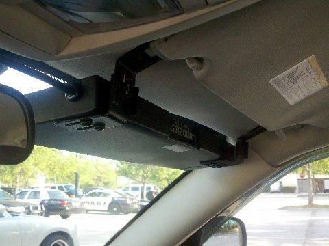
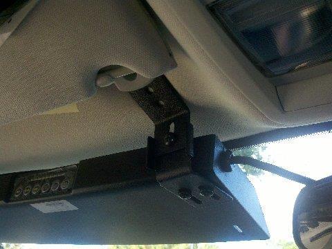
7 Attach mounts to visor unit Turn the visor light so that the bottom is facing up and you see 4 screw holes on each visor side This is where the mounting brackets will attach to the visor Mounting bracket part with slats connects to visor Use (4) screws and (4) washers to attach mounting brackets to each side of visor light bar loosely tighten so you can adjust to fit your vehicle later during the install The Two Slat bracket belongs on the innermost side of the visor. The Six slat belongs on the outermost side of the visor. 7


8 Mounting your visor light to the vehicle The visor light uses the existing screws located in your vehicles visors. You will still be able to use your vehicle visors. Loosen the vehicle visor screws enough to slide the visor light fork brackets into place under the visor screws. At this time determine if you will need to add the additional flash back guard extender. Not all vehicles will need this part. Be sure the visor is very close to the windshield so you will not get light flashing back into your vehicle when the unit is on and flashing. see Flash Guard Extender instructions if this part needs to be installed. Add rubber stripping to edge of visor light flash guard or visor light flash guard extender depending on the mounting option you choose for your install. This rubber stripping will create a protective barrier between your visor light and windshield to prevent damage during vehicle vibration and movements. Once the visor unit is in place tighten the visor screws so the visor light is stable and tightly in place Adjust brackets up/down and left/right to get a proper fit then tighten all brackets securely. 8
9 9

10 Flash Back Extender Not all vehicles will need this part. Be sure the visor is close to the windshield so you will not get light flashing back into your vehicle when the unit is on and flashing If the visor light unit is not close enough add the flash back extender The flash guard extender will attach to the visor light at the end of the visor light flash guard Use (2) small screws on each side of the flash guard extender and attach to the visor light Adjust accordingly to fit your vehicle 10

11 CONTROL AND POWER Cig Adapter Plug into your vehicles cig plug to power the visor light bar Includes on/off button on cig adapter Red light will turn on when depressing the toggle button on the cig adapter to denote light is on Red light will turn off when depressing the toggle button on the cig adapter it denote light is off The tip of the cig adapter has a fuse located in it. Occasionally you may need to change the fuse as regular maintenance on this unit. To access the fuse screw the black portion of the tip of the cig adapter counter clockwise. To replace the tip screw the black portion of the tip clockwise. Hard wiring to the battery or a separate siren box or control switch This unit can be hard wired by cutting the cig adapter off This will give you two wires positive + and negative By removing the cig adapter you will be removing the fuse located inside of the cig adapter tip it is imperative when hard wiring to your 12 volt power source you add a inline fuse to safe guard the unit from damage Connect to power accordingly to positive and negative feeds (If you reverse the polarities you will blow the circuit board) Please Note: Hard wiring the unit will void your warranty if not installed by a certified Emergency Vehicle Technician please see warranty policy for further information on this 11
12 Your install is complete if you need further instruction please contact us IMPORTANT: See Extreme Tactical Dynamics policies regarding hard wiring. Extreme Tactical Dynamics warranty covers manufacturer defects. Warranty is void if the unit is rewired, disassembled, improperly wired, or installed incorrectly. If you have any issues or concerns, please contact customer service immediately. Thank you for giving Extreme Tactical Dynamics your business. We know you have options when buying emergency vehicle lights and we are pleased you chose us. ALL RIGHTS RESERVED. NO PART OF THIS INSTRUCTION OR OPERATION MANUAL MAY BE COPIED, DISTRIBUTED, TRANSMITTED, OR SHARED IN ANY FORM BY ANY MEANS. THIS IS NOT LIMITED TO RECORDING, PHOTOCOPYING, ELECTRONIC DELIVER, OR.PDF REPRODUCTION. CUSTOMERS OF EXTREME TACTICAL DYNAMICS MAY DOWNLOAD AND PRINT THIS INFORMATION FOR USE WITH PRODUCTS SOLD TO THE CUSTOMER. HOWEVER, NO PART OF THE MANUAL AND INSTRUCTIONS CAN BE REPRODUCED, DOWNLOADED, DISSEMINATED, PUBLISHED, OR TRANSFERRED EXCEPT WITH THE PERMISSION OF EXTREME TACTICAL DYNAMICS. 12
STL K-Force 18 and Micro 14 LED Mini Light Bar
 2809 Business Park Dr Buda TX 78610 Phone 800.757.2581 Fax 844.894.2652 Email customerservice@speedtechlights.com STL K-Force 18 and Micro 14 LED Mini Light Bar Operation Manual and Instructions Congratulations,
STL Raptor - X TIR Interior LED Visor Light Bar
 2809 Business Park Dr Buda TX 78610 Phone 800.757.2581 Fax 844.894.2652 Email customerservice@speedtechlights.com STL Raptor - X TIR Interior LED Visor Light Bar Operation Manual and Instructions Congratulations,
STL Striker /Virtue Interior LED Traffic Series
 2809 Business Park Dr Buda TX 78610 Phone 800.757.2581 Fax 844.894.2652 Email customerservice@speedtechlights.com STL Striker /Virtue Interior LED Traffic Series Operation Manual and Instructions Congratulations,
STL Ceptor Series Running Board Light Stick
 2809 Business Park Dr Buda TX 78610 Phone 800.757.2581 Fax 844.894.2652 Email customerservice@speedtechlights.com STL Ceptor Series Running Board Light Stick Operation Manual and Instructions Congratulations,
2809 Business Park Dr Buda Texas STL Wireless Remote Switch Box Operation Manual and Instructions
 STL Wireless Remote Switch Box Operation Manual and Instructions Congratulations, you are the owner of a STL Wireless Remote Switch Control Box! Your bar is equipped with the latest technology and features
STL Raptor Series Interior LED Visor Light Bar
 2809 Business Park Dr Buda TX 78610 Phone 800.757.2581 Fax 844.894.2652 Email customerservice@speedtechlights.com STL Raptor Series Interior LED Visor Light Bar Operation Manual and Instructions Congratulations,
STL Mounting Brackets
 2809 Business Park Dr Buda TX 78610 Phone 800.757.2581 Fax 844.894.2652 Email customerservice@speedtechlights.com STL Mounting Brackets Operation Manual and Instructions Congratulations, you are the owner
STL Dart TIR Exterior LED Traffic Advisor Arrow Stick
 2809 Business Park Dr Buda TX 78610 Phone 800.757.2581 Fax 844.894.2652 Email customerservice@speedtechlights.com STL Dart TIR Exterior LED Traffic Advisor Arrow Stick Operation Manual and Instructions
STL Raptor Linear Interior LED Visor Light Bar
 2809 Business Park Dr Buda TX 78610 Phone 800.757.2581 Fax 844.894.2652 Email customerservice@speedtechlights.com STL Raptor Linear Interior LED Visor Light Bar Operation Manual and Instructions Congratulations,
STL Rear Raptor Linear Interior LED Visor Light Bar
 2809 Business Park Dr Buda TX 78610 Phone 800.757.2581 Fax 844.894.2652 Email customerservice@speedtechlights.com STL Rear Raptor Linear Interior LED Visor Light Bar Operation Manual and Instructions Congratulations,
218 Trademark Dr Buda Texas STL 80-Watt Strobe Hideaway Kit Operation Manual and Instructions
 STL 80-Watt Strobe Hideaway Kit Operation Manual and Instructions Congratulations, you are the owner of a STL 80-Watt Strobe Hideaway Kit! Your bar is equipped with the latest technology and features at
218 Trademark Dr Buda Texas STL Supreme II Control Switch Box(U.S. Patent Pending) Operation Manual and Instructions
 Operation Manual and Instructions") STL Supreme II Control Switch Box(U.S. Patent Pending) Operation Manual and Instructions Congratulations, you are the owner of a STL Supreme II Control Switch Box! Your bar is equipped with the latest
STL Supreme II Control Switch Box(U.S. Patent Pending) Operation Manual and Instructions Congratulations, you are the owner of a STL Supreme II Control Switch Box! Your bar is equipped with the latest
STL Z - 3 TIR LED Surface Mount
 2809 Business Park Dr Buda TX 78610 Phone 800.757.2581 Fax 844.894.2652 Email customerservice@speedtechlights.com STL Z - 3 TIR LED Surface Mount Operation Manual and Instructions Congratulations, you
STL K-Force Micro 50 TIR LED Light Bar
 2809 Business Park Dr Buda TX 78610 Phone 800.757.2581 Fax 844.894.2652 Email customerservice@speedtechlights.com STL K-Force Micro 50 TIR LED Light Bar Operation Manual and Instructions Congratulations,
STL K-Force Micro 21 TIR LED Mini Light Bar
 2809 Business Park Dr Buda TX 78610 Phone 800.757.2581 Fax 844.894.2652 Email customerservice@speedtechlights.com STL K-Force Micro 21 TIR LED Mini Light Bar Operation Manual and Instructions Congratulations,
218 Trademark Dr Buda Texas STL Striker-6 TIR LED Traffic Advisor Operation Manual and Instructions
 STL Striker-6 TIR LED Traffic Advisor Operation Manual and Instructions Congratulations, you are the owner of a STL Striker-6 Series LED Light Bar! Your bar is equipped with the latest technology and features
218 Trademark Dr Buda Texas STL Dual Carbine 50 Curved Hybrid Off Road LED Light Bar Operation Manual and Instructions
 STL Dual Carbine 50 Curved Hybrid Off Road LED Light Bar Operation Manual and Instructions Congratulations, you are the owner of a STL Dual Carbine 50 Curved Hybrid Off Road LED Light Bar! Your bar is
218 Trademark Dr Buda Texas STL K-Force 27 TIR MaxGen (U.S. Patent No. D703,082) Operation Manual and Instructions
 Operation Manual and Instructions") STL K-Force 27 TIR MaxGen (U.S. Patent No. D703,082) Operation Manual and Instructions Congratulations, you are the owner of a STL K-Force Series Light bar! Your bar is equipped with the latest technology
STL K-Force 27 TIR MaxGen (U.S. Patent No. D703,082) Operation Manual and Instructions Congratulations, you are the owner of a STL K-Force Series Light bar! Your bar is equipped with the latest technology
218 Trademark Dr Buda Texas STL Aries 60 Linear Tow Generation IV (U.S. Patent No. D700,098) Operation Manual and Instructions
 Operation Manual and Instructions") STL Aries 60 Linear Tow Generation IV (U.S. Patent No. D700,098) Operation Manual and Instructions Congratulations, you are the owner of a STL Aries Tow Series Light bar! Your bar is equipped with the
STL Aries 60 Linear Tow Generation IV (U.S. Patent No. D700,098) Operation Manual and Instructions Congratulations, you are the owner of a STL Aries Tow Series Light bar! Your bar is equipped with the
U L T I M A T E R A D A R / L A S E R D E F E N S E S Y S T E M
 S m a r t e r Q u i e t e r M o r e A c c u r a t e U L T I M A T E R A D A R / L A S E R D E F E N S E S Y S T E M Installation Manual PASSPORT 9500ci Comes Complete Front Radar Receiver Miniature weatherproof
Installation Guide. FOR TECHNICAL ASSISTANCE, VISIT
 Installation Guide The HG2 Runner Package is an extremely versatile emergency lighting system designed for maximum visibility with a minimal footprint. HG2 Runners were developed to enhance the outline
NOTE. Figure 2. Mounting Configurations (View shown from rear of LED Bar) Figure 3. Rear Deck Mounting NOTE
 Figure 3. Rear Deck Mounting NOTE") Page 5 Page 6 TO REAR OF VEHICLE (STANDARD WIRING) LIGHTBAR 2 TO FRONT OF VEHICLE (OPTIONAL WIRING) LIGHTBAR 1 LIGHTBAR 1 LIGHTBAR 2 Figure 2. Mounting Configurations (View shown from rear of LED Bar)
Page 5 Page 6 TO REAR OF VEHICLE (STANDARD WIRING) LIGHTBAR 2 TO FRONT OF VEHICLE (OPTIONAL WIRING) LIGHTBAR 1 LIGHTBAR 1 LIGHTBAR 2 Figure 2. Mounting Configurations (View shown from rear of LED Bar)
Challenger 60 & 70 Tow Series. Installation & User Manual
 Challenger 60 & 70 Tow Series Installation & User Manual 1 2 Contents Chapter 1 Safety & Precautions for Installers & Users...5 Safety Messages to Installers & Users Before Installation...5 Safety Messages
Automotive: Lightbars
 ENGINEERING COMPANY INC. 51 Winthrop Road Chester, Connecticut 06412-0684 Phone: (860) 526-9504 Fax: (860) 526-4078 Internet: www.whelen.com Sales e-mail: autosale@whelen.com Canadian Sales e-mail: canadiansales@whelen.com
INSTALLATION & OPERATION MANUAL
 INSTALLATION & OPERATION MANUAL SuperVisorTL IMPORTANT: SuperVisorTL Interior Lighting System 2011 Ford F150 CONTENTS: Introduction... 2 Unpacking & Pre-Installation...2 Installation & Mounting...3-4 Wiring
ResQ 48 & 60. Installation & User Manual
 ResQ 48 & 60 Installation & User Manual 1 2 Contents Chapter 1 Safety & Precautions for Installers & Users...5 Safety Messages to Installers & Users Before Installation...5 Safety Messages to Installers
Installation and Operation Instructions Safety Director Arrow
 Installation and Operation Instructions Safety Director Arrow! WARNING! Failure to install or use this product according to manufacturers recommendations may result in property damage, serious bodily/personal
S TROBE BEACO N INSTALLATION & OPERATION MANUAL MODEL 92XXX 12 JOULE MODEL 95XXX 15 JOULE MODEL 98XXX 8 JOULE MODEL 99XXX 20 JOULE FULL RANGE
 INSTALLATION & OPERATION MANUAL FULL RANGE SERIES 90 MODEL 92XXX 12 JOULE MODEL 95XXX 15 JOULE MODEL 98XXX 8 JOULE MODEL 99XXX 20 JOULE FULL RANGE S TROBE BEACO N IMPORTANT: Contents: Introduction... 2
GENERAL REQUIREMENTS:
 Installation & Service Manual Slim Rack Bunk Lift System with Control Box 1510000199 or 1510000260 Content Copyright Power Gear Issued: January 2013 # 3010002675, Rev. 0D Installation and Service Manual
CAUTION. Even Brakes with a black cable need second vehicle kit Even Brakes with a blue cable need second vehicle kit 98450
 cable not included cable not included Even Brakes with a blue cable need second vehicle kit 98450 Even Brakes with a black cable need second vehicle kit 98400 Check the Even Brake serial number before
INSTALLATION & OPERATION MANUAL
 INSTALLATION & OPERATION MANUAL SUPERVISOR TL SuperVisor TL Interior Lighting System Chevrolet Tahoe 2007 Model CONTENTS: Introduction... 2 Unpacking & Pre-Installation... 2 Installation & Mounting...
Automotive: Lightheads
 ENGINEERING COMPANY INC. Winthrop Road Chester, Connecticut 00 Phone: (0) 0 Fax: (0) 07 Internet: www.whelen.com Sales email: autosale@whelen.com Canadian Sales email: canadiansales@whelen.com Customer
INSTALLATION & OPERATION MANUAL
 INSTALLATION & OPERATION MANUAL SUPERVISOR TL SuperVisor TL Interior Lighting System Expedition 2007 Model CONTENTS: Introduction... 2 Unpacking & Pre-Installation... 2 Installation & Mounting... 3-4 Wiring
Installation Instructions
 patent pending Portable Proportional Braking System Installation Instructions Part number 9400 Towing and Suspension Solutions ROADMASTER, Inc. 6110 NE 127th Ave. Vancouver, WA 98682 800-669-9690 Fax 360-735-9300
INSTALLATION MANUALS FOR THE SUPERVISOR. Click below to go to the appropriate model. For all others, contact Customer Service at (314)
") INSTALLATION MANUALS FOR THE SUPERVISOR Click below to go to the appropriate model. For all others, contact Customer Service at (314) 426-2700. Ford Crown Victoria Chevy Impala Ford Explorer Chevy Tahoe
INSTALLATION MANUALS FOR THE SUPERVISOR Click below to go to the appropriate model. For all others, contact Customer Service at (314) 426-2700. Ford Crown Victoria Chevy Impala Ford Explorer Chevy Tahoe
Installation Instructions
 Portable Proportional Braking System Installation Instructions Part number 9400 Time Tested Time Proven ROADMASTER, Inc. 6110 NE 127th Ave. Vancouver, WA 98682 800-669-9690 Fax 360-735-9300 roadmasterinc.com
COBRA Model # - D X, D X, D-20109, D-20209, D-20409, D20609, D-20809, D-21015, D-20119, D Cobra Series- Instruction Manual V.
 V3.0 Cobra Series- Instruction Manual V.3 COBRA Model # - D-20109-1X, D-20215-2X, D-20109, D-20209, D-20409, D20609, D-20809, D-21015, D-20119, D-21109 This instruction manual serves as a guide for the
INSTALLATION & OPERATION MANUAL
 INSTALLATION & OPERATION MANUAL NON DOME LIGHT VERSION DOME LIGHT VERSION SuperVisor-MC - 2011 Dodge Charger With Multi Color Torus Technology Interior Lighting System CONTENTS: Introduction... 2. Unpacking
ARTICLE BEGINNING FUSES & CIRCUIT BREAKERS * PLEASE READ FIRST * ALL BUT JETTA ( ) Fuses & Circuit Breakers Volkswagen ELECTRICAL
 Fuses & Circuit Breakers Volkswagen ELECTRICAL") Article Text ARTICLE BEGINNING Fuses & Circuit Breakers 1987-96 Volkswagen ELECTRICAL FUSES & CIRCUIT BREAKERS * PLEASE READ FIRST * The fuse panel is located under the left side of the dash board by the
Article Text ARTICLE BEGINNING Fuses & Circuit Breakers 1987-96 Volkswagen ELECTRICAL FUSES & CIRCUIT BREAKERS * PLEASE READ FIRST * The fuse panel is located under the left side of the dash board by the
FUSION Model # - FN-XXXX, *See website for Part # Fusion Innerbar. Instruction Manual V2.0
 Fusion Innerbar Instruction Manual FUSION Model # - FN-XXXX, *See website for Part # This instruction manual serves as a guide for the Fusion Innerbars. IMPORTANT! Please read through all provided instructions
P.A. System Installation Manual
 P.A. System Installation Manual 100 Watt Public Address w/ Sirens WARNING: To ensure the longevity of your system, reading and following these instructions are recommended. Make sure to change filters
FENIEX ROCKER PANEL Series MODEL # D-11971
 www.feniex.com E-mail: Support@feniex.com Support line: 1.800.615.8350 Installation and Operational Guide FENIEX ROCKER PANEL Series MODEL # D-11971 This instruction manual serves as a guide for the Rocker
Do not install and/or operate this safety product unless you have read and understand the safety information contained
 Installation and Operation Instructions ED3766 TRI Color Directional LED Available in various color combinations, the ED3766 Directional LED is a surface mount, tri-color warning light that is ideal for
Opticom TM Model 795H-INT with Bracket for Deck or Inside Windshield Mounting
 2562625A REV. A 1211 Safety Message to Installers Opticom TM Model 795H-INT with Bracket for Deck or Inside Windshield Mounting People s lives depend on your safe installation of our products. It is important
Installation and Service Manual M² Sync Room Slideout System without Room Lock Connectors on Control Box
 Installation & Service Manual M² Sync Room Slideout System w/o Room Locks: for Slideout Control Box# 1510000143 and 1510000198 Figure 1 01/13 Power Gear #3010002088 Rev. 0C Installation and Service Manual
STRX-9 100% TAKE CONTROL INSTRUCTION MANUAL READY-TO-RUN. w/ Adult Supervision
 STRX-9 w/ Adult Supervision INSTRUCTION MANUAL 18005 100% READY-TO-RUN TAKE CONTROL Index Included Items Important Notes Battery Installation Charging Instructions Transmitter/Receiver Binding Basic Controls
NOTE. Installation and Service Manual Dual Planetary Gearmotor Slim Rack Slide Out System
 Installation & Service Manual Slim Rack In-Wall Slide Out System Control Box Part Number 1510000199 Content Copyright LCI/Power Gear Issued: December 2014 #3010002588, Rev. 0E Installation and Service
Ford Mustang V6 OEM-Style Fog Light Kit Parts List: Quantity: Tool List:
 2015-2017 Ford Mustang V6 OEM-Style Fog Light Kit Parts List: Quantity: Tool List: LED Foglights/ Bezels 2 Flat head & Phillips screwdriver (if you ordered part#3600) Ratchet & Socket set OR Wiring harness
Vehicle Rear Observation System With Integrated Parking Sensors
 Vehicle Rear Observation System With Integrated Parking Sensors Model: CAMSBAR Installation/User Manual Features: 2.5" LCD Color Display 2 Ultra Sonic Rear Obstacle Sensors On-screen Display Function Automatically
Do not install and/or operate this safety product unless you have read and understand the safety information contained in this manual.
 Installation and Operation Instructions MR Tri- Light Available in various color combinations, the MR Directional LED surface mount, tri-color warning light is ideal for a wide variety of auxiliary warning
Embedded Rack Slide-out System
 Embedded Rack Slide-out System SERVICE MANUAL Rev: 02.16.2017 Page 1 Electric Embedded Rack Slide-out System TABLE OF CONTENTS Safety Information 3 Product Information 3 Operation 4 Extending Slide-Out
LIGHTNING PLUS 120 WATT / 6 OUTLET VOLT POWER SUPPLY & STROBE LIGHT KIT 6 Different Light Patterns 8006 SERIES INSTALLATION INSTRUCTIONS
 LIGHTNING PLUS 120 WATT / 6 OUTLET 12-24 VOLT POWER SUPPLY & STROBE LIGHT KIT 6 Different Light Patterns 8006 SERIES INSTALLATION INSTRUCTIONS Your purchase of Wolo s LIGHTNING PLUS strobe light system
Installation Manual VEHICLE HANDSFREE KIT KRY ericssonz
 Installation Manual VEHICLE HANDSFREE KIT KRY 101 1613 ericssonz TABLE OF CONTENTS NOTICE! This manual covers Ericsson and General Electric products manufactured and sold by Ericsson Inc. This manual is
GENERAL REQUIREMENTS:
 Installation & Service Manual Slim Rack Bunk Lift System with Control Box 1510000199 or 1510000260 Content Copyright Power Gear Issued: January 2013 # 3010002675, Rev. 0D Installation and Service Manual
APOLLO Model # - F-12013, F-22013, D-50115, D-50215, D-50415, D-50615, D-50815, D Apollo Series- Instruction Manual V.3
 Apollo Series- Instruction Manual V.3 APOLLO Model # - F-12013, F-22013, D-50115, D-50215, D-50415, D-50615, D-50815, D-51015 This instruction manual serves as a guide for the Apollo Series. IMPORTANT!
INSTALLATION & OPERATION MANUAL. WingMan. WingMan. Interior Lighting System FORD CROWN VICTORIA UPPER REAR DECK LIGHT BAR IMPORTANT: CONTENTS:
 INSTALLATION & OPERATION MANUAL WingMan CONTENTS: WingMan Interior Lighting System FORD CROWN VICTORIA UPPER REAR DECK LIGHT BAR Introduction... 2 Unpacking & Pre-Installation... 2 Installation & Mounting...
ENFORCER TM 6201-IQ ELECTRONIC SIREN
 ENFORCER TM 6201-IQ ELECTRONIC SIREN INSTALLATION & OPERATION MANUAL CONTENT PAGE UNPACKING 2 INTRODUCTION 2 STANDARD FEATURES 2 INSTALLATION & MOUNTING 3 MOUNTING THE ENFORCER TM 6201 3 WIRING & ADJUSTMENTS
Installation & Calibration
 Installation & Calibration ED2-AT Series SkidWeigh System Lift Truck On-board Check Weighing With Accumulative Load Weight Total ED2-AT Series SkidWeigh V.1.1 General Installation Guide This ED2-AT Series
INSTALLATION & OPERATION MANUAL. WingMan. WingMan IMPORTANT: Interior Lighting System Crown Victoria REAR DECK LIGHT BAR
 INSTALLATION & OPERATION MANUAL SHORT VERSION WingMan LONG VERSION WingMan Interior Lighting System Crown Victoria REAR DECK LIGHT BAR CONTENTS: Introduction... 2 Unpacking & Pre-Installation... 2 Installation
AVH-2330NEX AVH-2300NEX AVH-1330NEX AVH-1300NEX
 AVH-2330NEX AVH-2300NEX AVH-1330NEX AVH-1300NEX DVD RDS AV RECEIVER Installation Manual Connection Precautions Your new product and this manual Do not operate this product, any applications, or the rear
Automotive: Lightbars
 ENGINEERING COMPANY INC. 51 Winthrop Road Chester, Connecticut 06412-0684 Phone: (860) 526-9504 Fax: (860) 526-4078 Internet: www.whelen.com Sales e-mail: autosale@whelen.com Canadian Sales e-mail: canadiansales@whelen.com
Plus SABRE LIGHTBARS
 INSTALLATION AND INSTRUCTION MANUAL Plus SABRE LIGHTBARS Models 5364LED, 5462LED, 5464LED and 5564LED PLIT445 REV. D 2/2/18 Keep any radio frequency sensitive equipment at least 20 from the bar and power
Owner s Manual Dual Planetary Gearmotor Auto Programming Slim Rack Slide Out System
 Owner s Manual Slim Rack In Wall Slide Out System With Control Box 1510000236 or 1510000276 Content Copyright LCI/PowerGear Issued: December 2014 #3010002814, Rev. 0F Owner s Manual Dual Planetary Gearmotor
harley davidson motorcycle equipment installation manual
 harley davidson motorcycle equipment installation manual (All mounting systems included in this manual were designed specifically for the Electra-Glide Model Harley Davidson Motorcycle. A current 2008
INFINITY-1 HALOGEN LIGHT BAR INSTALLATION MANUAL 7000 SERIES
 INFINITY-1 HALOGEN LIGHT BAR INSTALLATION MANUAL 7000 SERIES Your purchase of a Wolo warning light is the perfect choice to compliment your vehicle. Wolo s warning lights are manufactured with the finest
INFINITY-3 STROBE LED BAR INSTALLATION MANUAL 7700 SERIES
 INFINITY-3 STROBE LED BAR INSTALLATION MANUAL 7700 SERIES Your purchase of a Wolo warning light is the perfect choice to compliment your vehicle. Wolo s warning lights are manufactured with the finest
95-98 CHEVY TRUCK INSTALLATION INSTRUCTIONS KIT #112 #113
 This body lift kit should only be installed on vehicles that are in good working condition. Before the installation begins, the vehicle should be thoroughly inspected for evidence of corrosion or deformation
DESCRIPTION & OPERATION
 AIR BAG RESTRAINT SYSTEM 1996 ACCESSORIES/SAFETY EQUIPMENT Toyota Air Bag Restraint System DESCRIPTION & OPERATION WARNING: To avoid injury from accidental air bag deployment, read and carefully follow
INSTALLATION INSTRUCTIONS
 CLASSIC EDITION WITH AUX-IN CHROME OR BLACK FINISH THANK YOU FOR CHOOSING STEEL HORSE AUDIO! Protect yourself and others from possible injury and property damage or loss. Pay close attention to all instructions,
Proper installation of this product requires the installer to have a good understanding of automotive electronics, systems and procedures.
 ENGINEERING COMPANY INC. 51 Winthrop Road Chester, Connecticut 06412-0684 Phone: (860) 526-9504 Fax: (860) 526-4078 Internet: www.whelen.com Sales e-mail: autosale@whelen.com Canadian Sales e-mail: autocan@whelen.com
BOLT-ON AND WELD-ON FLUSH FLOOR SLIDEOUT SYSTEMS OPERATION AND SERVICE MANUAL
 BOLT-ON AND WELD-ON FLUSH FLOOR SLIDEOUT SYSTEMS OPERATION AND SERVICE MANUAL TABLE OF CONTENTS SYSTEM...... Warning........ Description...... Prior to Operation OPERATION... Main Components... Mechanical...
SlimRack Bed Lift System OEM INSTALLATION MANUAL
 SlimRack Bed Lift System OEM INSTALLATION MANUAL Rev: 07.11.2018 TABLE OF CONTENTS System Information 2 Safety Information 3 Resources Required 3 General Requirements 3 Installation 4 SlimRack Bed Lift
Grind Pro Series. Operator Manual. Manufacture by:
 Grind Pro Series Operator Manual Manufacture by: 1 Bench Sander Series INTRODUCTION The Bench Sander series are compact, durable machine designed for fast, complete finishing work. It will deliver efficient,
UNISTEER Performance Products UNIVERSAL HOT ROD ELECTRA-STEER KIT
 UNISTEER Performance Products UNIVERSAL HOT ROD ELECTRA-STEER KIT 8051500 BEFORE YOU START PLEASE READ! Designing steering systems requires an understanding of steering function and design. If you are
3-in-1 Electric Jack, Impact Wrench & Air Compressor
 Item No. : 7010 3-in-1 Electric Jack, Impact Wrench & Air Compressor User s Manual We are constantly improving our products so specifications are subject to change without notice. Visit our website for
B4850BTPACF Fender Mounting Instructions for MIN4050, MIN950 & MIN1550 Fenders
 B4850BTPACF Fender Mounting Instructions for MIN4050, MIN950 & MIN1550 Fenders STEP 1 A. Unpack all cartons and lay out parts. B. Compare the parts with hardware kit B4850BTPA as shown in Figure 1. B4850BTPACF
FORD F-250, F-350, 4WD 2 COIL SPRING LEVELING KIT INSTALLATION INSTRUCTIONS
 3651 N. Highway 89 Chino Valley, AZ 86323 (928) 636-7080 www.p-a-g.net FORD F-250, F-350, 4WD 2 COIL SPRING LEVELING KIT INSTALLATION INSTRUCTIONS 2008 KIT# FL223PA Many states now have laws restricting
LED FLASHER GND CONTROL FPC4N
 LED FLASHER GND CONTROL FPC4N Installation/Operations Manual FPC4N Table of Contents Applicable Models... 2 Introduction... 2 General Warnings... 2 Unpacking &Pre-Installation Check... 3 Installation &
Optional Extras 1. Part #AT7107A Privacy Handset 2. Part # HMN4058A Potato Mic.
 The AdvanceTec Hands-free car kit is designed for use with all AdvanceTec car kit cradles as well as all Motorola OEM car kit cradles for safe and convenient vehicular operation. The Car Kit (AT6538A)
EW-38. Owner s Manual. (888)
") EW-38 Owner s Manual www.ewheelsdealers.com (888) 305-0881 0 Table of Contents 1. Before you operate your scooter.... 2 2. Scooter initial operation...... 2 3. Technical specification... 3 4. Mirror Assembly..
EW-38 Owner s Manual www.ewheelsdealers.com (888) 305-0881 0 Table of Contents 1. Before you operate your scooter.... 2 2. Scooter initial operation...... 2 3. Technical specification... 3 4. Mirror Assembly..
INSTALLATION CLAMP-ON FORK MOUNTED DRIVING LIGHTS 5015
 CLAMP-ON 5015 PARTS INCLUDED 2 Driving Lights 2 Side Mount Clamps-43mm/49mm 1 Hardware Kit Including: 2 49mm Spacers 4 43mm Spacers 2 Pivot Dome Washers 2 3/8-16 Serrated Hex Nut 1 Wiring Kit for Driving
Model FM100 INSTALLATION & OPERATION MANUAL SPEAKER/FLUSHMOUNT IMPORTANT: MODEL FM100C OR FM100V Patent Pending
 INSTALLATION & OPERATION MANUAL MODEL FM100C OR FM100V Patent Pending Model FM100 SPEAKER/FLUSHMOUNT Contents: Introduction... 2 Unpacking & Pre-Installation... 3 Installation & Mounting... 3 Maintenance...
AutoFarm GPS AutoSteer Hardware Installation Guide
 AutoFarm GPS AutoSteer Hardware Installation Guide Supported Models: Case AFX-8010 Combines PN: 602-0039-01-A Special Requirements Tools This list consists of special tools required to complete the installation.
DC Singledock Vehicle Wiring and Mounting Instruction
 Installation Sheet Page 1 of 8 DC Singledock Vehicle Wiring and Mounting Instruction Archived August 2003 Operating information is contained in the MX1 Cradle Reference Guide. Table of Contents Introduction...2
275 Beacon 12v MODELS PERMANENT, MAGNETIC MOUNT BEACONS
 INSTALLATION & OPERATION MANUAL 275/275AH/275ASH/ 275AMH BEACON 275 Beacon 12v MODELS PERMANENT, MAGNETIC MOUNT BEACONS Contents: Introduction... 2 Unpacking & Pre-Installation... 2 Installation & Mounting...
FX817 INSTALLATION & OPERATION MANUAL IMPORTANT:
 INSTALLATION & OPERATION MANUAL FX817 Contents: Introduction...2 Features and Specifications...2 Current Draw...2 Installation & Mounting...3 Wiring...3 Operation...4 Maintenance...4 Troubleshooting...4
42 WATT LED TRIPLE BEAM WORKLIGHT
 42 WATT LED TRIPLE BEAM WORKLIGHT OWNER S MANUAL WARNING: Read carefully and understand all ASSEMBLY AND OPERATION INSTRUCTIONS before operating. Failure to follow the safety rules and other basic safety
Model Due to continuing improvements, actual product may differ slightly from the product described herein.
 12 volt Oooga horn Model 96291 Assembly And Operation Instructions Due to continuing improvements, actual product may differ slightly from the product described herein. 3491 Mission Oaks Blvd., Camarillo,
North American Signal Co. Be Seen, Be Safe. CLKE6H90(S) System with Hi/Lo option Installation Guide
 System with Hi/Lo option Installation Guide") North American Signal Co. www.nasig.com Be Seen, Be Safe. CLKE6H90(S) System with Hi/Lo option Installation Guide Safety First This installation guide is intended to provide all the necessary information
North American Signal Co. www.nasig.com Be Seen, Be Safe. CLKE6H90(S) System with Hi/Lo option Installation Guide Safety First This installation guide is intended to provide all the necessary information
INSTALLATION CONSTELLATION DRIVING LIGHTS 5009
 INSTALLATION CONSTELLATION DRIVING LIGHTS 5009 PARTS INCLUDED 1 Right Driving Light with Turn Signals 1 Left Driving Light with Turn Signals 1 Installation Component Kit Including: 8 Insulated Male Spades
Australian Warning Systems Pty Ltd assumes no liability for any loss resulting from the use of this warning device.
 AS SERIES DIRECTIONAL ARROWS With AC5 Control System Installation Instructions IMPORTANT! Read all instructions before installing and using. Installer: This manual must be delivered to the end user. Australian
TOYOTA Yaris Hatchback EC REARVIEW MIRROR Preparation
 Preparation Part Number: PT374-02090 Kit Contents Item # Quantity Reqd. Description 1 1 Auto Dimming Mirror Assembly w/ shift area light 2 1 Hardware bag Hardware Bag Contents Item # Quantity Reqd. Description
FN-4918 INSTRUCTION MANUAL SCAN HERE
 FENIEX // 2018 // INSTRUCTION MANUAL Is this the latest version? SCAN HERE FN-4918 INSTRUCTION MANUAL Feniex Product Copyrights This price List and the mentioned Feniex products include or describe copyrighted
Retrofit Steering Column
 Retrofit Steering Column Installation Instructions for 1970-75 Camaro For Part # s: 1620860010, 1620860020, 1620860051, 1620869910, 1620869920, 1620869951, 1625860010, 1625860020, 1625860051, 1625869910,
Back-Up Sensor System
 Back-Up Sensor System Model No.: PKC0RE Owner s Manual and Warranty Information OFF ON 0.4m/1.3ft 0.6m/2.0ft 1.0m/3.3ft 1.2m/4.0ft 1.5m/5.0ft LEFT RIGHT Read these instructions completely before using
WF-5110R True Sine Wave Inverter
 Operator s Manual WF-5110R True Sine Wave Inverter WF-9900 Series WF-5110R ( The Inverter model number is located on the label on top of the enclosure) Distributed in the U.S.A. and Canada by ARTERRA DISTRIBUTION
Fusion GPL 49 Instruction Manual
 FENIEX. 2018 INSTRUCTION MANUAL Fusion GPL 49 Instruction Manual 49 This instruction manual serves as a guide for the Fusion 49 GPL. Model # FN-4916 IMPORTANT! Please read through all provided instructions
INSTALLATION & OPERATION MANUAL
 INSTALLATION & OPERATION MANUAL MODEL OL15F Patent Pending OSCILASER TM HEADLAMP MODULE Contents: Introduction... 2 Unpacking & Pre-Installation... 2 Installation & Mounting... 2-3 Maintenance... 4 Cleaning...
Fender Mounting Instructions for MIN100, MIN150, MIN1600, MIN161200, MIN1900, MIN2200, MIN221800, MIN2260, MIN2480 & MIN9950 Fenders
 STEP 1 100126 Fender Mounting Instructions for MIN100, MIN150, MIN1600, MIN161200, MIN1900, MIN2200, MIN221800, MIN2260, MIN2480 & MIN9950 Fenders A. Unpack all cartons and lay out parts. B. Compare the