C10 C12. Combine Harvester Instruction Book. Sampo Rosenlew Ltd P.O.Box 50 FIN PORI /2015 Englanti
|
|
|
- Jared Wilkerson
- 6 years ago
- Views:
Transcription

1 C10 C12 Combine Harvester Instruction Book Sampo Rosenlew Ltd P.O.Box 50 FIN PORI /2015 Englanti
2
3 THIS BOOK The purpose of this book is to enable the Operator to familiarize himself with the combine. It is of utmost importance that the Operator becomes familiar with the structures, adjustments and maintenance of his combine. Compliance with the advice and instructions given in this manual guarantees the best results at the lowest costs. Have this manual always in the cab, in the special pocket reserved for it, for convenient reference. This manual provides descriptions of as well as operating and maintenance instructions for several models in the series. Every combine does not have all the described features. The actual structure as well as the number of accessories and optional equipment depend on what was agreed in the delivery contract. This is to be kept in mind when reading the manual. Item Technical Specifications has a description of the features of the combine. It does, however, not include retro-fitted accessories. The Manufacturer reserves the right to modify the structure, adjustments or accessories of the combine as well as the service and maintenance instructions without further notification. SAMPO ROSENLEW Ltd 1
4 CONTENTS This book 1 Safety Precautions 3 Warning Signs 7 Type Marking 9 Technical Specifications 11 Conformity to the EU Directives 13 Acceptance Inspection 14 Opening of the Guards 15 Structure and Functions of the Combine 20 Cut-away Picture of the Combine 21 Operator Controls and Instruments 24 Key to the Symbols 25 Operation and Adjustment 26 Threshing Equipment 38 Comvision 65 Automatic Cutting Height Control (AHC) 75 DHC 82 Driving and Threshing Instructions 83 Approximate Settings 90 Service and Maintenance 91 Transmission 117 Hydraulics 119 Electrical Equipment 123 Lubrication 130 Summary of Periodical Maintenance Procedures 133 Storage when Not in Use 134 Recommended Tools and Accessories 136 Screw Joints 136 Discarding of the Combine 137 Conversion to Maize Harvesting 138 Conversion to Sunflower Harvesting 143 Conversion to Rice Harvesting 145 2

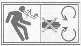
5 SAFETY PRECAUTIONS Read carefully these instructions on safety and use before starting to operate the combine. Time spent in becoming familiar with the instructions now will save you money or may even spare you from injury. Before accepting the delivery of the combine, make sure it conforms to the delivery contract. Do not fit the combine with any accessories not approved of by the Manufacturer. The Manufacturer of the Combine is not responsible for any damage or injury caused by such accessories either to people or property. 1. TRANSPORTATION ON A VEHICLE OR BY RAIL Make sure you know the measurements and weights of the combine and the transporter. Comply with any regulations governing the transportation. Use increased tyre pressures (2 2.5 Bar) to improve stability. Fix the combine securely in the transporter. For road transport lower the cutting table fully or disengage it. 2. DRIVING IN TRAFFIC When driving on public roads, comply with the relevant statutory traffic regulations. Remember the combine has rear-wheel steering. The brake pedals must be latched together. Test brake functions before driving on the road. Brake smoothly as the rear wheels of the combine easily rise from the ground when applying the brakes violently. The safety switch on the instrument panel must be depressed. (The switch is released to its top-most position by turning the knob clockwise). The threshing equipment must be disengaged, the straw dividers removed and the unloading pipe locked for road transport. The knife shield and the front warning signs shall be fitted onto the table, if it is permitted to drive on the road with the cutting table engaged. (Fitting of the front warning signs in accordance with the enclosed illustrations, A1). The front and rear lights and the rear-view mirrors shall be correctly aligned. Never drive downhill with the gears in neutral. Never carry passengers on the combine. Never use the combine for transporting goods. Always have the grain tank empty when driving on the road. 3. THRESHING Get familiar with the structure of the combine by studying the manual before starting threshing. Wear appropriate clothing. Avoid loose clothing that may get caught in moving parts. Keep the doors closed when working to prevent dust and noise entering the cabin. Use of hearing protectors is recommended.make sure the protective guards are properly attached and in good condition. Sound the signal to warn people around the combine before starting the engine. Adjust the rear-view mirrors before starting to ensure good visibility of the road or the working area behind. Never use the combine for anything but threshing. Manual feeding of crops onto the cutting table is prohibited. A1 3


6 Before starting, particularly reversing, make sure that everybody nearby is aware of your intentions. Test the brakes as soon as you start, and stop immediately if the brakes or steering operate defectively. Never adjust the seat or steering wheel while driving. Never leave the cab while the combine is moving. Never leave the engine running unattended. Do not open the guards with the engine running. Do not mount, or allow others to mount, on top of the grain tank or the straw walkers with the engine running Beware of the cutting mechanism and the rotating chopper knife. Keep in mind that with the chopper rotating, there is a 20 m no-access danger zone behind it. /Fig. A2) Drive carefully on hillsides; the combine may overturn, particularly with the grain tank full. The combine cab is no safety cab. THE RIGHT-HAND SIDE DOOR MAY BE USED AS AN EMERGENCY EXIT. PULL UP THE HANDLE, AND OPEN THE WINDOW. FIG. EXIT. Note the recommended safety distances when threshing under power lines. Stop the engine before cleaning or servicing the combine. Stop the combine and the engine immediately if there is an alarm or any abnormal sounds or smells. Find out the reason for them, and remove the problem before carrying on with threshing. Support or lock the cutting table and the reel before going beneath them. Never clean the combine without the proper equipment. When leaving the combine, lower the cutting table, lock the parking brake, stop the engine and remove the ignition key. A2 EXIT SAFETY DISTANCES WHEN THRESHING UNDER OPEN-WIRE POWER LINES The minimum space between the combine and power lines with voltage must be in accordance with the enclosed illustration, in which the danger zone is darkened. Low-voltage power lines (240/400V), fig. A3, can be distinguished from high-voltage lines (over 1 kv) by the smaller insulators and the fact that there are usually 4 low-voltage lines. In case the height or voltage of the power line is difficult to estimate, the Electric Company shall be consulted. In Case of an Accident If there is an accident despite all precautions, keep calm and consider carefully what to do. First try to reverse the combine away from the power line. If there are other people near, ask them to check that the combine is not stuck in the line. If the combine is just leaning against the lines, try to disengage it by driving. Follow the advice from the people nearby. Due to their own safety, they shall stay a minimum of 20 metres from the combine touching A3 4


7 the power line. If the combine cannot be disentangled, and you have to leave the combine, jump down with your feet together in order not to touch the combine and the ground simultaneously. Do not make yourself a conductor through which electricity can pass; the real danger lies in touching the combine and the ground simultaneously. et away from the combine jumping either with your feet together or with only one foot on the ground at a time. Otherwise the electric field on the ground may create a fatal electric current between your legs. You will be safe at a distance of 20 metres from the combine. Beware of broken power lines lying on the ground. A combine touching a power line may catch fire. Leave the combine immediately if smoke starts coming from the tyres. Make sure the combine is guarded at a safe distance. Do not try to get on the combine even if the power in the power lines may seem to have gone off. Remember that open-wire lines never have a blown fuse, but they are always dangerous unless made dead by an electrician. Even if the power went off, it may come back on in a while due to technical reasons. This may be repeated several times. Contact the Electric Company and inform them about the exact site of the accident. By doing this, any risk can be eliminated and the fault repaired. Ask the Electric Company for advice and follow it. Inform them about any contact with power lines even if there was no actual damage. A4 Source: Koneviesti Magazine 15/87 4. REPAIR AND SERVICE Always keep the combine in good condition. Check the condition of fast moving parts daily. Pay special attention to the transmission mechanism and the rotating chopper knives. Replace defective parts before they become dangerous. Make sure that all the guards and other safety equipment are in good condition and mounted before the combine is used. Clean, repair and service the combine with the transmission and engine off, the ignition key off the ignition and the master switch in its off position. Disconnect the battery minus cable before repairing the engine or the electrical instruments. Do not use inappropriate tools to connect and disconnect the battery. Do not make an open fire or smoke near the battery. Handle the battery acids with care. Do not add air in the tyres without a pressure gauge due to risk of explosion. Do not add coolant with the engine running. Do not remove the radiator cap from an overheated engine. Do not refuel with the engine running. Do not smoke while fuelling. Do not adjust the hydraulic working pressure without a pressure gauge due to possible damage to the hoses. When servicing the hydraulics, be aware of the A5 A6 5


8 high pressure in the system. Make sure there is no pressure in the system or in the pressure reservoir before disconnecting the connectors. Never use over-sized fuses; they involve risk of accident. Never start the combine with anything but the ignition key. When refitting a wheel, tighten the fixing screws to the correct torque. Attach accessories such as the trailer using the appropriate equipment. Tow the combine only from designated points. This symbol in the manual refers to a special risk involved in taking a certain measure, due to which extra caution shall be practiced. 5. THE LAWS AND REGULATIONS Combine harvester is a complex device, and dangerous if misused. User manual must always be preserved with the machine at the place reserved for it and if needed, new drivers should be instructed to operate the machine your area. 6. FIRE SAFETY Two factors are needed to start a fire: flammable material and ignition; oxygen is always available. Threshing generates a lot of light and highly flammable dust. Therefore it is important to clean the combine on a regular basis and the engine compartment daily. Oil and fuel leaks increase the risk of fire. Repair any defects immediately. High temperature near the exhaust pipe makes the area fire-prone. A fire may also be caused by a short circuit in the electric system, slipping of an overloaded belt, a damaged bearing or overheating of the brakes. Make sure there is at least one 6-kilo class AB fire extinguisher located in its marked place on the combine at all times. In particularly dry and dusty circumstances another similar extinguisher is to be placed near the engine compartment. 6
9 MARKING OF THE DANGER POINTS The structures of the combine have been designed to be as safe to use and service as possible. This manual provides instructions on how to eliminate any risks there may be in the use of the combine. The danger points have been marked on the combine using danger symbols. The following diagram shows the location of the markings. Check regularly that the markings are clearly visible. On the following page you will find the key to these symbols. The danger symbols are based on the international ISO standard. Location of the Danger Symbols


10 DANGER SYMBOLS Danger How to avoid it No Symbol Subject to danger due to insufficient information Read the manual before starting the combine 1 A raised part may fall down Support raised parts before going under them 2 Gap in belt drive Stop the engine and remove the ignition key before removing any guards 3 Getting entangled in moving parts Stop the engine and remove the ignition key before removing any guards and /or reaching a the danger zone 4 Getting entangled in rotating auger Stop the engine and remove the ignition key before removing any guards 5 Getting entangled in rotating auger Do not reach into an opening with the engine running 6 Falling into moving machinery Stop the engine and remove the ignition key before removing any guards 7 Danger caused by hurtling objects Keep at a safe distance from the combine 8 Kickback or upward motion of arm handle Stop the engine and remove the ignition key before inserting the handle 9 8


11 TYPE MARKING When ordering spare parts or service, always quote the type marking and number shown on the machine plate of the combine. When ordering parts for the cutting table, also quote the type marking and number shown on the cutting table. When ordering engine parts, also quote the engine number. Write down the numbers of the combine and engine on this page (and in the spare parts list). Combine type plate Cutting table type plate Combine number Engine number Note! Left side of the combine = The side of the cab with the stairs Right side of the combine = The side with the fuel tank 9
12 TECHNICAL SPECIFICATION C10 &C12 Cutting table Reel Threshing Cylinder Concave Straw Walkers Shaker Shoe Grain Tank Engine Sisu Power C10 C12 Traction Drive 10
13 Driving speed (km/h)* Final Hydrostatic Traction Drive drives CIT Turning radius (m) Tyres / Air pressure (bar) Wheel track (m) Volumes (litres) 11
14 Weight (kg) C10 C12 Cutting table (m) 4,5 4,8 5,1 5,7 6,0 6,3 6,9 Weight (kg) Chopper weight (kg) Maize table 6 row (kg) Length (m) C10 C12 Width (m) Height with cabin (m) Noise level in cabin db(a) (O. E. C. D.-1967/6) 12
15 13
16 ACCEPTANCE INSPECTION AND GETTING STARTED The combine leaves the factory packaged in an appropriate way to ensure undamaged delivery. Before using the combine, the following measures shall be takes. Read the instruction manual carefully. Remove any loose parts stored in the grain tank. Check the combine for any transport damage or lost parts. (If necessary, contact the dealer or the transport company.) Make sure the combine complies with the purchase contract. (If necessary, contact the dealer.) Attach any parts removed before shipment such as lamps, mirrors, etc. Put the fire extinguisher in its place. Check the oil and coolant levels. In case the combine has been stored for over a year, perform annual service according to the manual. Check and lower tyre pressures to comply with the manual. Make sure the threshing mechanism can rotate unhindered and that there are no foreign objects inside the combine before starting the engine. Engage the cutting table if delivered disengaged. Assemble, fit and adjust the straw dividers as shown in the drawings in the spare parts catalogue Fit the crop lifters as instructed in the manual. Test-run the combine as instructed in the manual under Storage when Not in Use. IMPORTANT NUMBERS Check and write down the following numbers: The combine serial number The cutting table serial number The engine serial number The cab key number The fuel tank key number 14


17 OPENING OF THE GUARDS To ensure safety, the movable guards in the combine have been equipped with a locking device. They cannot be opened without the appropriate tool supplied with every combine, hanging on a hook on the back wall of the cab. (The guards can also be opened with a 13 mm socket wrench or a screw driver.) The guards get locked automatically when closed. Some guards also have additional clamps. Unlock the guard at the left end of the cutting table, fig. B1b by turning the locking device counter-clock wise. To open the guard, pull the handle outwards and lift the guard slightly upwards at the same time. The guard gets locked automatically when closed. B1b The side guards, fig. B2b, are released by placing the tool in the hole at the lower part of the guard and turning counter-clockwise. The guard opens when the lower edge is pulled outwards. The guard rests on the gas springs. The guard is locked automatically when closed. The lower guards on the combine can be opened. The front and rear of the guard can be opened separately. The front of the lower guard is opened by unlocking the front of the guard using the tool. Fig. B2c. To open the rear, slack screws on both sides of the rear guard and remove guard. There is space for a tool kit on the left behind the front guard. B2b B2c 15

18 The rear guard of the chopper, fig. B3, (straw spreader) is released by opening the side locks on both sides of the combine. The guard gets locked in the upper position. When the guard is lowered, make sure the guard gets locked at the required height on both sides. Choppers belt guard is opened by loosening the bolt on the guard and turning the cover open.the guard is secured in the upper position with a rubber strip. Straw hoods plastic cover is opened by lifting the bottom upwards, then loose the bolts of the inner guard and remove inner guard. B3 16


19 The locking on the guard on the engine air intake is opened by placing the tool on the rear corner of the guard and turning counter-clockwise, fig. B4. The top door to the straw walker compartment is locked with a hexagonal screw. B4 Open the locking on the grain tank cover, fig. B5, by placing the tool in the hole and turning counter-clockwise. B5 Open the cover above the engine compartment like this: Unlock the locks on both sides of the cover using a tool and lift upwards Fig. B6. B6 17

 B7 Fire extinguisher is placed in the stairs.")
20 Windscreen cleaning When cleaning the windscreen, climb on top of the crop elevator A and hold on of the top arms of the mirrors B (Figure B7.) B7 Fire extinguisher is placed in the stairs. (A, Figure B8). B8 18

21 Access ladder, grain tank CAUTION: Shut off the engine and set the park brake. B9 Use ladder A to get into grain tank. (Figure B9.) 19
22 STRUCTURE AND FUNCTIONS OF THE COMBINE Standard Threshing Mechanism The cutting and feeding equipment take the crops in for threshing. The straw dividers limit the crop to be cut and bring it within reach of the reel. The reel, together with the crop lifters, lift up the laid-down crop up and take it from the cutting knife onto the table auger. The table auger gathers the cut crop and feeds it onto the crop elevator, which takes the crop forward to be threshed. Stones and other heavy objects are pushed to the stone trap thus preventing damage to the threshing mechanism. The threshing mechanism separates the grains from the straw. The threshing cylinder beats the grain off on the concave. Most of the threshed grain and chaff go through the concave into the grain pan. The rear beater and the concave extension take the threshed straw onto the straw walkers. The separating and cleaning equipment sieves the grains. The straw walkers separate the grains from the straw and eject the straw out to the field from the rear of the combine. The grains run along the bottom grooves to the grain pan. The grain pan takes the threshed material to the shaker shoe. The chaff and any light remains are sorted topmost in the grain pan with the grain at the bottom. The air stream from the fan lifts the light chaff in the air and transports it over the shaker shoe and out of the machine. Heavier grains and any partly threshed material fall through the chaff sieve. Any larger remains move out along the sieve. Clean grain falls onto the grain auger through the grain sieve and is transported from there by the grain elevator and filling auger to the grain tank. The grains and occasional straw bits, which lie on the shaker shoe extension, fall to the returns course to be re-threshed. The chopper cuts and spreads the straw. After the straw walker, the straw is either discharged uncut onto the field or taken to the chopper, which cuts and spreads it out. 20
23 CUT - AWAY PICTURE OF THE COMBINE 1. Pick-up reel 5. Stone trap 9. Fan 13. Shaker shoe 17. Straw walkers 21. Bottom augers 2. Cutter bar 6. Threshing cylinder 10. Grain pan 14. Return auger 18. Straw alarm 22. Filling auger 3. Table auger 7. Concave 11. Grain elevator 15. Sieves 19. Straw chopper 23. Grain tank 4. Crop elevator 8. Rear beater 12. Auger housing 16. Sieve extension 20. Unloading pipe 24. Engine 25. CSP 21
24 STRUCTURE AND FUNCTIONS OF THE COMBINE, The TS Threshing Mechanism The cutting and feeding equipment take the crops in for threshing. The straw dividers limit the crop to be cut and bring it within reach of the reel. The reel, together with the crop lifters, lift up the laid-down crop up and take it from the cutting knife onto the table auger. The table auger gathers the cut crop and feeds it onto the crop elevator, which takes the crop forward to be threshed. Stones and other heavy objects are pushed to the stone trap thus preventing damage to the threshing mechanism. The threshing mechanism separates the grains from the straw. The cut crop first comes onto the pre-cylinder, which gently separates the most easily threshable grains and ejects them through the pre-concave to the front of the grain pan. The pre-cylinder also evens out the feed onto the main cylinder. The rest of the grains are threshed off by the main cylinder and concave. Most of the threshed grain and chaff go through the concave into the grain pan. The rear beater and the concave extension take the threshed straw onto the straw walkers. The separating and cleaning equipment sieves the grains. The straw walkers separate the grains from the straw and eject the straw out to the field from the rear of the combine. The CSP ruffling drum placed above the straw walkers intensifies the separation of loose grains from the straw by opening a fluffier area into the straw flow. The grains run along the bottom grooves to the grain pan. The grain pan takes the threshed material to the shaker shoe. The chaff and any light remains are sorted topmost in the grain pan with the grain at the bottom. The air stream from the fan lifts the light chaff in the air and transports it over the shaker shoe and out of the machine. Heavier grains and any partly threshed material fall through the chaff sieve. Any larger remains move out along the sieve. Clean grain falls onto the grain auger through the grain sieve and is transported from there by the grain elevator and filling auger to the grain tank. The grains and occasional straw bits, which lie on the shaker shoe extension, fall to the returns course to be re-threshed. The chopper cuts and spreads the straw. After the straw walker, the straw is either discharged uncut onto the field or taken to the chopper, which cuts and spreads it out. 22
25 CUT - AWAY PICTURE OF THE COMBINE, the TS Threshing Mechanism 1. Pick-up reel 6. Threshing cylinder 11. Grain elevator 16. Sieve extension 21. Pre-concave 26. Engine 2. Cutter bar 7. Concave 12. Auger housing 17. Straw walkers 22. Unloading auger 27. CSP 3. Table auger 8. Rear beater 13. Shaker shoe 18. Straw alarm 23. Bottom augers 4. Crop elevator 5. Stone trap 9. Fan 10. Grain pan 14. Return auger 15. Sieves 19. Straw chopper 20. Pre-cylinder 24. Filling auger 25. Grain tank 23
 A Comvision-display B Multi-function Lever C Steering Wheel H Brake Pedals F Instrument Panel E Gear Lever D Traction Speed Control Lever G Seat I Buddy Seat J Concave Clearance Indicator K")

 A Traction Speed Control Lever B Cutting Table Start/Stop C Threshing Mech.")
26 OPERATOR S CONTROLS AND INSTRUMENTS, Operator s Platform / Cab (fig. D1b) A Comvision-display B Multi-function Lever C Steering Wheel H Brake Pedals F Instrument Panel E Gear Lever D Traction Speed Control Lever G Seat I Buddy Seat J Concave Clearance Indicator K Hand Brake D1b Instrument Panel (fig. D2b) A Thermometer B Fuel Gauge C Tank Cover Lift D Reversing of Cutting Table and Feeding Mech. E Concave Clearance Adjustment F Concave Clearance Adjustment G Direction of Straw Chopper Spray H Direction of Straw Chopper Spray I Working Lights J Working Lights K Safety Switch L Emergency Flasher M Rotating Flasher N Vertical Knife, left (optional) O Vertical Knife, right (optional) P 4WD Switch (optional) Q Engine faulty code R Main switch S Electric Outlet T Ignition Lock, Starter / Stopper D2b Switches (fig. D3b) A Traction Speed Control Lever B Cutting Table Start/Stop C Threshing Mech. Start/Stop D Fan Speed Adjustment E Electric accelerator (depending on the engine type) F AHC/DHC G AHC Pre-setting height H AHC Automatic height I Armrest angle adjustment J Cylinder Speed Adjustment K Reel Speed Automatic/ Manual L Cover M Unloading Start/Stop D3b 24
27 SIGNS AND SYMBOLS Concave Clearance Adjustment Reel Fore & Aft Control Ignition Lock Master Switch (electric) Ignition Signal Oil Warning Light Alternator Warning Light Engine Revolutions, lever control Engine Revolutions, electric control Gear Change Diagram Horn Reel Speed Control Air Volume Speed Control Air Direction Control Lever Reversing Switch of Cutting Table Four-wheel Drive Rotating Flasher Emergency Flasher Swinging of Unloading Pipe Flasher Lifting of Grain Tank Cover Dip Switch Headlights Working Lights Windscreen Wiper Temperature Control Air Conditioning Hand Brake Cutting Table Height Cutting Table Side Tilt Reel Height Grain Tank ½ Full Grain Tank Full Grain Elevator Alarm Bottom Auger Alarm Return Auger Alarm Straw Alarm Coolant Temperature Alarm Straw Guide for Chopper Straw Guide for Long Straw Threshing Mechanism Switch Air Filters Blocked Speed Control Lever Cutting Table Switch Grain Tank Unloading Switch Threshing Cylinder Speed Hydraulic Filter Blocked Hydraulic Oil Too Hot Emergency Exit Engine Malfunction Light Reel automatic / manual EXIT 25
28 OPERATION AND ADJUSTMENT Operation Hierarchy of Electrical Controls. The connection of the electrical controls meets the safety requirements set on the machine. In the following descriptions you can read on which conditions each operation can be started. Engine Start-up: The main power switch is in the on position The traction lever is in its med-position. Start-up of the Threshing Mechanism: The engine is running The safety clutch is pulled up The chopper gets switched on = the pressure sensor in the chopper connection cylinder connects the drive current (if the straw plate is turned to the to the chopper position) If yellow switch is left up, it must be pushed down and then lifted up again. Chopper Start-up: Will start when the threshing mechanism is started if the limit switches in the straw guide plate connect the drive current Cutting Table Start-up: The threshing mechanism is running = the pressure sensor in the connection cylinder of the threshing mechanism connects the drive current If yellow switch is left up, it must be pushed down and then lifted up again. Reel Start-up: Will start when the table is started The operation requires that the pressure sensor on the table clutch connects the drive current Vertical Knife Start-up: Will start when the table is started, if the knife is switched on by the control switch. The drive current is supplied by the cutting table electric control. Start-up of Feed Equipment Reverse: The engine is running The cutting mechanism has been disengaged Start-up of Unloading: The engine is running The safety clutch is pulled up Swinging of the Unloading Pipe: The engine is running The safety clutch is pulled up Lifting and Lowering of the Cutting Table, Lifting and Lowering of the Pick-up Reel, Adjustment of Reel Distance, Cutting Table Side Tilt: The engine is running Adjustment of Pick-up Reel Speed: The cutting table is running (The pressure sensor in the table clutch connects the drive current) Chaff Spreader Start-Up: Will start when the threshing mechanism is started Rotating Light 0, automatic and on position. When automatic, light rotates when grain tank is half loaded. 26


29 STEERING WHEEL Position Can Be Adjusted (Triple Adjustment Steering Column) To adjust the steering column angle, depress pedal A and tilt the whole column forward or backward. The steering column folds in the middle. Lift the lever B up and adjust the steering wheel to the desired position. To adjust the height of the steering wheel, lift the lever C (Fig. K1c) up and adjust the steering wheel to the desired position K1b K1c 27


30 OPERATOR S SEAT Adjustments Spring Suspended Grammer Seat (fig. K2a) To adjust the fore and aft position, release lever A under the seat and move the seat to the required position. Adjust the height by raising the seat manually. There are three alternative heights at 20 mm intervals. When the seat is raised above the highest position, it will drop to the lowest position. Adjust the suspension to suit the operator s weight by turning adjustment screw B. The screw tightens when turned clockwise. Adjust the backrest angle by releasing lever C and turning the backrest. Adjust the armrest angle by turning hand wheel D. The height of the armrest can be adjusted by moving its fixing point. D A C B Air Suspended Grammer Seat (fig. K2b) K2a To adjust the fore and aft position, release lever A under the seat and move the seat to the required position. To adjust the height, raise adjustment lever B briefly after being seated. The seat will be automatically adjusted to suit the driver s weight. From this position the seat can be moved up and down by turning the adjustment lever in the required direction. Adjust the suspension to suit the weight of the operator by turning screw C. To adjust the backrest angle, release lever F and turn the backrest. To adjust the lumbar support, turn hand wheel G. Adjust the armrest angle by turning hand wheel H. The height of the armrest can be adjusted by moving its fixing point. C B H A G F K2b Electrically adjustable mirrors K2c Turn the switch to position A when adjusting left mirror Turn the switch to position B when adjusting right mirror 28

 The hand brake operates on the intermediate shaft of the gears.")

31 BRAKES (fig. K3) While Driving and Turning The brakes operate on the front wheels through the drive shafts. They may be used separately as steering brakes by releasing locking pin A. When driving on the road, the brake pedals must be latched together. K3 HAND BRAKE (fig. K5) The hand brake operates on the intermediate shaft of the gears. Use the brake only when parking, and fully release it before starting. A symbol light warns of an unreleased parking brake. That light is on only when ignition is switched on. K5 Drive Lever (K6) Combines speed and direction is controlled with a drive lever. To adjust the lever position, slacken nut B and turn the lever in the ball-and-socket joint. Tighten the screws and the nut after adjustment to ensure the lever will not move while driving. K6 29


32 TRANSMISSION Hydrostatic Transmission has Three Speed Ranges (fig. K7) Engine power is transmitted to the hydraulic pump by means of gearing. Transmission from the pump onto the hydraulic motor of the gearing takes place by means of liquid. Pump output is adjusted steplessly on a drive lever between position 0 and the maximum +/-. There are three gear speed ranges, which are selected using lever A, fig. K7. Ranges 1 and 2 are for threshing and range 3 for driving on the road. Never use range 3 on the field. Gears should be changed on level ground with drive lever B, fig. K7, in its mid position. Transmission is hydraulically eased. The front of knob A has a switch, which is pressed to open K7 the gear lock hydraulically. The engine must be running to provide pressure in hydraulics! The speed and direction of the combine are controlled using lever B, fig. K7. With the lever in its mid position the combine is stationary if the gear is on and the engine running. The combine will move forward when the drive lever is pushed forward from its mid position. The further the lever is pushed the higher the speed. To reverse the combine, pull the lever backward from the mid position. A combine equipped with hydrostatic transmission must never be parked using only the gear, but the parking brake must always be engaged. A hydraulic engine cannot keep the combine stationary for any length of time. Shift the gear into neutral to enable towing, if the engine cannot be started for some reason. (In case of eased gearboxes the gear lock prevents the shifting of gear into neutral.) Optional FOUR-WHEEL DRIVE (fig. K8) The combine is equipped with assistant four-wheel drive. There is hydraulic parallel connection between the rear and the front wheels. When using speed range 2, the front and the rear wheels drive in relation to the axle weight. Due to the parallel connection the peripheral speeds of the wheels adapt to different driving conditions even within speed range 1. Rear-wheel drive is switched on electrically using switch on the instrument panel, fig. K8 (see operator s controls and instruments page 24) The coupling can be done with the combine moving. Four-wheel drive may be used in speed ranges 1 and 2 only. When towing the combine, four-wheel drive must be off and the engine running to allow the wheel motors to be disengaged. Switch four-wheel drive off when driving down a steep hill. The combine may rush forward unless the rear wheels grip the ground. K8 30
33 Starting the ENGINE with the Ignition Key (fig. K9) The combine is equipped with a safety ignition system, which prevents the combine from moving when the engine is being started. It allows the start-up to take place only with the traction speed control lever in neutral. It is advisable, however, always to start the engine with the gear in neutral. Electrically Controlled Engines, Fig. K9a Electrically controlled engines have no throttle lever but a throttle control switch with three positions. On idle the switch B rear is depressed. Fig. K9a. The power is switched on by turning the ignition key to the right. The alternator and oil pressure warning lights will come on. To start turn the key to position HS. Do not start until the lights have come on. It takes some time to activate the control unit. Cold weather starting at below +5 o C The engines are equipped with a pre-heating resistance controlled by the engine control unit. In cold weather it functions automatically. When pre-heating switches itself on, control light C, fig. K9a, comes on. Start the engine as soon as the control light goes off. After the engine has started, the heater switches itself on again for some time. Fault Codes on Electrically Controlled Engines Engine malfunction light E K9a, functions as a fault code indicator for the engine control unit. For more information, see the engine manual. The ignition lock allows only one start-up function. Turn the key to the STOP position before restarting. K9a Combines with hydrostatic transmission must not be started in temperatures below 15 o C as the oil is too stiff and the machinery may get damaged. 31
34 Stopping of the ENGINE / Listening to the Radio Before stopping the engine, move the throttle into the idling position and disengage the threshing mechanism. Turn the ignition key to the STOP position. In order to listen to the radio with the engine not running, turn the ignition key left from the STOP position while pressing the key down. 32

35 THE STAIRS (fig. K10a) The stairs can be turned forward to the front of the wheel to reduce combine width. They can be turned standing on the ground by lifting locking lever A. The turn can also be done standing on the cab landing by lifting knob B to release the locking. The stairs shall always be turned forward when the combine is driven on the road without the cutting table. MASTER SWITCH (fig. K11) Controls Electricity for the Whole Combine There is a master switch to control the electrical equipment of the combine. It is located on the left-hand side, on the rear guard. The current is connected in position 2. To disconnect the current, turn the switch to position 1, in which position the key may be removed. Electrical Master Switch K10a K11 Depending on the specification the switch may also be electrically controlled. The operating switch is in the cab (see page 24). The switch disconnects current to all other electrical devices except to its own control circuit. 33

36 CAB (fig. K12) Fresh-air Fan Provides Good Ventilation K12 The 4-speed fan is started using switch A. To change the airflow direction, turn nozzles 1 at the front top of the cab. Air coming into the fan is taken through detachable coarse mesh and fine filters. To keep up the fan capacity and to secure the purity of the air, the filters have to be cleaned daily and replaced often enough to prevent harmful impurities and fungi from clogging the filters. In dusty conditions it is necessary to clean the coarse mesh filter several times a day. By opening nozzles 2, cab indoor air can be circulated through the fan, which reduces the need for outdoor air and thus reduces the risk of blocked filters. The windscreen wiper is controlled by switch B. Cover D can be removed and a radio set installed in the space. HEATER Provides Additional Heat from the Engine The air in the cab is heated by a heating element in which the engine coolant circulates. Turn switch E to the right to increase the amount of coolant circulating in the element. This will increase the temperature in the cab. Open nozzles 2, fig. K12, to re-circulate the heated cab air. This will further increase the temperature in the cab. AIR CONDITIONER Cools the Air in the Cab The cab can be equipped with an air conditioner system. Turn switch C to the right to switch on and regulate the cooler. Open nozzles 2 to re-circulate the cooled cab air, which will further cool down the cab. Note! A difference of over 8 o C between indoor and outdoor temperatures is harmful to your health. Keep the cab door closed when the air-conditioning is on. 34


37 TOWING (figs. K14 and K15) Allowed from Towing Points Only The combine may be towed from designated points only. When towing forward, the towline is hooked to the link on the front axle, fig. K14. When towing backward, wind the towline round the rear carrier, fig. K15. The towline must not be wound round the rear axle. With the combine on tow, the operator must be in the cab and the engine running to enable steering. The brakes must be latched together and the gears in neutral. Four-wheel drive must be off. Unless the engine can be started, the combine must be towed with great care; without power steering engaged, the combine is slow and heavy to handle. When towing on the road, statutory traffic regulations must be followed. K14 Correct LIFTING of the Combine (figs. K14 and K15) The combine may be lifted using the designated points only. It shall be lifted on level, sturdy ground. The grain tank shall be empty. The lifting capacity of the jack shall be a minimum of 10 tons. If an ordinary jack is used to raise the combine, a sufficiently high and firm, one-piece platform with an area of a minimum of 300 x 300 mm is to be placed underneath the jack. Before the lift, the combine must be immobilized by placing wedges in front of and behind the wheels on the ground. Use a sturdy trestle to secure the combine in its raised position. If several wheels are to be removed at the same time, the ground surface of the trestles is to be a minimum of 600 x 600 mm. K15 35


38 TABLE TRAILER (figs. K16, K17 and K18) for Road Transport of Wide Cutting Tables The need for a table trailer depends on farm conditions. The trailer may be necessary for a 3.9 m and 4,2m cutting table if transportation is necessary on busy, narrow roads. Cutting tables 4.5 and wider should always be transported on a trailer in order not to inconvenience traffic and risk the safety of road users. The trailer has no traction unit, but shall be towed attached to the combine. No other cargo except for a cutting table must be transported on the trailer, nor must any other attachment except for the trailer be hooked to the combine towing hook. In case the trailer is attached to another traction unit, a tractor, for example, the attachment shall be made in accordance with the instructions, and the statutory traffic regulations shall be followed. K16a Placing the Table on the Trailer Disengage the table from the combine as instructed in paragraph Removing the Table. Connect hoses for reel drive and reel horizontal movement to each other. Protect the other connectors with rubber cups. Place the trailer on level ground and align its frame with the ground by adjusting the cam wheel. Pull locking pins A into their open position, fig. K16. Remove the straw dividers from the table and place them on the brackets on the trailer. Depending on the type of dividers, the brackets are either at the front or the back of the axle. Lock the dividers with ring cotter and/or locking pivot B, fig. K16. When needed, adjust the guides of the adjustable divider in a narrower position so that the table bottom does not touch the divider. K16b K16c 36


, hook the table with the winch and tighten.")
39 Drive the table above the trailer from the left-hand side so that the knife is level with the trailer marking sticks and brackets A at the rear of the table, fig K17, are between carriers B. Lower the table slowly. Make sure the table is positioned correctly: Reverse slowly so that the rear end of the table is against both the carrier limiters. Lower the crop elevator further so that it becomes disengaged from the cutting table and back up the combine with caution. Raise the crop elevator as soon as possible. Push the rear locking pins into their locking position. The trailer is equipped with a winch, which can be used to pull the trailer to the combine hook after the combine has been reversed near the trailer. Hook the trailer to the combine and plug in the electric cable. Place the winch on the axle (fig17b), hook the table with the winch and tighten. K17 Attaching of the Cutting Table to the Combine is done in reverse order. In case the trailer must be left on the road temporarily, place appropriate warning signs. Connect hydraulic hoses and the PTO shaft, Fig. K18. Tighten hydraulic hose fittings all the way to the bottom. If there is pressure in the hoses, a spanner may be needed. However, the fittings do not need to be tightened to any certain torque. Trailer on Tow Extreme caution shall be exercised when towing the trailer. The total length of the vehicle is approx. 16 m, so turning the vehicle requires space. Do not turn the rear wheels to their extreme position as the trailer arm may touch the rear wheel and the vehicle will get stuck. However, if this is the case, back up the combine and use the steering brake at the same time. Reverse very carefully. Watch the trailer movements in the mirror. K17b K18 37
 When the safety switch is pressed, all engaged mechanisms (threshing, chopper, cutting table and unloading) stop.")

40 THRESHING EQUIPMENT SAFETY SWITCH There is safety switch on the instrument panel (See page 24). It must be in its top-most position before any mechanisms can be switched on. (It will rise when the knob is turned clockwise.) When the safety switch is pressed, all engaged mechanisms (threshing, chopper, cutting table and unloading) stop. The safety switch also stops the reversing of the feeding equipment. The unloading pipe cannot be turned with the safety switch pressed. The switch must always be depressed when driving on the road! WARNING LIGHTS and CONTROL LIGHTS There are control lights on the right A-pillar to indicate the mode of combine functions. A B C D E F G H I J K L M N O P Q R S T U V W X Y Charging not working Engine oil pressure too low pre-heating Engine alert light Engine overheated Air filter blocked Hand brake engaged Head lights Flasher Blockage in hydraulic filter Hydraulic liquid overheated Max. height exceeds 4 m Unload. pipe between its extreme pos. 4WD switched on Straw guide for chopper Blockage in the grain elevator Blockage in the bottom return auger Straw guide for long straw Blockage in the vertical return auger Blockage in the chaff hood Grain tank full CSP alarm Cutting table heavily on ground Grain tank ¾ full Hour Meter L2 Instruments (fig. L2b) are located in right A-pillar A B Warning and control ligths Comvision-display L2b 38

41 STRAW DIVIDERS (fig. L3) Have to be Adjusted The straw dividers are fitted on both sides of the cutting table. Their height is adjusted by means of slide pieces D with holes. Depending on the specification the dividers can be of the following types: Long torpedo dividers with fixed frames Short torpedo dividers with fixed frames Medium-long torpedo dividers with foldable frames Arc-type dividers Adjust guide plates A and B to suit the threshing conditions. The outside guide tube is attached to the divider at the front and to the table side at the rear. The adjuster for the tube is at the rear. Always attach the tube on the side of the uncut crop. Long dividers are used to thresh long-strawed crops such as rye and oats. Short dividers are used to thresh short-strawed crops such as barley and wheat. Dividers with foldable frames are suited for different crops. They do not need to be removed but can be turned to their transport position. Arc-type dividers are suited for short-strawed crops and crops that do not need dividing but are pressed down in a narrow section, such as turnip rape and flax. L3 The straw divider can be replaced with an electric vertical knife. It is particularly efficient when threshing oil plants. CROP LIFTERS (fig. L4) Spaced Correctly. Below you can see the appropriate number of crop lifters for different table widths: 3.9 m m m m m m m m 22 L4 Attach the crop lifters with the knife finger fixing screw as shown in the figure. The numbers in the figure indicate the number of finger spaces. The crop lifters operate well if clearance to the ground is 8 10 cm, which clearance also prevents stone pick. In some cases, for example, when threshing peas, it may be advisable to install more lifters, maybe even in every other knife finger. 39


42 REEL ADJUSTMENTS Four Adjustable Settings (figs. L5 and L6) 1 Reel height is controlled by switch B, fig. L5, on the traction speed control lever. The reel rises when the top button is pressed and falls when the bottom one is pressed. 2. Reel speed is controlled by switches E fig. L5, at the front of the traction speed control lever. Speed can only be adjusted when the reel is rotating. 3. The fore and aft adjustment is made by switches D, fig. L5. The clearance increases when the left-side button is pressed and vice versa. At the same time press shift switch at the front of the lever. 4. The blade angles are adjusted by pulling at button F and turning the adjustment lever in the required direction, fig. L6a. When harvesting laid-down crops, the tines shall be adjusted to gather the crops efficiently. The torque of the reel is restricted by means of a relief valve in the control valve. L5 Do not adjust the reel in its rear-most position if the tine angle is adjusted rearwards. The tines may reach the table auger and get damaged. Place locking A on the reel, fig. L6b, in the support position if working beneath a raised reel. L6a L6b 40


43 CUTTING KNIFE Must Be Kept in Good Condition! No actual knife adjustments can be made during threshing. The knife must be in perfect condition to produce good threshing results. For more precise service and adjustment instructions, see under Maintenance. A spare knife is stored in the case at the top of the table. TABLE AUGER (fig. L7) Height and Finger Positions Are Adjustable Adjust the feed auger vertically to suit the amount of straw in the crop being threshed. Average clearance X is mm. When threshing e.g. heavy rye or turnip rape, adjust clearance X between the auger and cutting table wider, approx mm. In special conditions even a 5 mm clearance can be used. To adjust, loosen screws A at both ends of the cutting table. Now the table auger can be lifted or lowered as required using adjustment screws B. Clearance between the feed auger and the bottom must be equal at both ends of the table. After moving the feed auger, check the drive belt tension. Loosen screw D to adjust the feed finger position with lever C at the right hand end of the cutting table. A minimum clearance of 10 mm is required between the feed fingers and the table bottom. The fingers must recede into the auger sufficiently early to allow the crop to be transported forward. Otherwise tall and damp crops in particular may wrap around the auger. L7 C D B A X Depending on the model, the table auger may be equipped with a safety switch. Adjustment instructions under Service and Maintenance. The Correct Height and Tension of the CROP ELEVATOR CHAIN (fig. L8) The elevator has a fixed top roller and a floating bottom roller to enable the elevator to fluctuate according to the flow of crop on it. Adjust the clearance between the bottom roller and the bottom of the elevator housing with screws C. Correctly adjusted, there should be a clearance of 20 mm between the lowest slats and the housing at middle of bottom roller. The tension of the crop elevator chain is adjusted with screws D. To check the tension, open the inspection door at the top of the elevator housing. The tension is correct when the deflection midway between the top and bottom rollers is approx. 80 mm. If the chain is assembled too tight, it wears out quickly and in some cases it may even break. L8 41
.")
. Pull up yellow switch to engage the table.")
44 TABLE AUGER AND CROP ELEVATOR REVERSE DRIVE (fig. L9) Eliminate Blockage from the Table Blockage in crop feed may stop the table auger and crop elevator as the safety switches slide. The blockage can be cleared by turning the feed equipment backwards. To do this, disengage the drive to the table and press reverse switch (fig. L9). The table auger and elevator will rotate in reverse direction and clear the blockage. NOTE! The reverse drive will only operate with the engine running and the safety switch in its upper position. Engaging and Disengaging of the CUTTING TABLE The cutting table is engaged and disengaged using switch (Fig. L9a). Pull up yellow switch to engage the table. The actual engagement is done by means of a hydraulic drum clutch. L9 L9a Caution! The cutting and feeding mechanism disengaged using the switch can start running when, for instance feeding disorders are eliminated from the table. Therefore, always stop the engine before any work is carried out on the table. A Supporting of the CUTTING TABLE (fig. L10) Before doing repairs and maintenance beneath the table, raise it to its full height and lock the support over the ram by means of lever A, fig. L10, on the right-hand side of the table auger. Do not use the cutting table support while driving on the road. L10 42
 Table height is controlled using switches A, fig. L11.")

45 Height of the CUTTING TABLE (figs. L11, L12 and L13) Table height is controlled using switches A, fig. L11. Cutting height is shown on the Comvision display, The cutting table is eased using a gas accumulator, and the warning light is lit when pressure off the table lifting is too low and table switched on. When warning light is lit, the table lies heavily against the ground, in which case soil or stones easily get onto the table and damage it. Adjustment of the pressure switch is done as follows: Pressure switch is located in the output line of the table valve (fig. L13). Warning light must be observed when adjusting pressure switch, table switched on. Alternatively conductivity of the switch can be measured with multimeter when engine not running. Warning light is lit when switch is conductive. L11 1. Lift table ca.10 cm off ground 2. Turn adjusting screw clockwise until warning light is lit (if not already litted) 3. Turn adjusting screw counter-clockwise until warning light goes off. Continue turning still yet 1/8 round after warning light goes off. More you turn switch open after warning light goes off, the more heavily table is allowed to lie against the ground before warning light is lit. Note. Warning light may blink also when lowering table. Side Tilt of the CUTTING TABLE The transverse position of the cutting table to the ground can be adjusted hydraulically using switches D on the traction speed control lever, fig. L11. (The same knobs adjust the reel clearance.) Side tilt may be needed on a sloping field when the combine tends to tilt downhill. L13 43

 Must Be Emptied Regularly The stone trap prevents stones from getting onto the concave. It is located between the crop elevator and concave.")
46 STONE BLOCK Behind the Knife An optional stone block can be fitted on the cutting table behind the knife. It has proved extremely useful on fields with a lot of small stones. They are stopped by the stone block and can be removed from there. Always stop the combine and the engine and fit the supports for the table and the pick-up reel before carrying out any work on the cutting table. STONE TRAP (fig. L14) Must Be Emptied Regularly The stone trap prevents stones from getting onto the concave. It is located between the crop elevator and concave. The hinged bottom can be opened and locked using lever A. The stone trap must be emptied daily; the contents of it must be of soft nature. When harvesting short stubble on stony fields, empty the stone trap more often. L14 Engage THRESHING MECHANISM (fig. L15) at Engine Idling Speed Only Engage and disengage the threshing mechanism using switch (fig. L15). Engage the threshing mechanism by pulling up yellow switch. The function is electro-hydraulic. The levers in the belt coupling are turned hydraulically. The chopper starts first if the chaff guide plate is for the chopper. The threshing mechanism is switched on after the chopper. NOTE! ENGAGE AND DISENGAGE THE THRESHING MECHANISM AT ENGINE IDLING SPEED ONLY. DO NOT INCREASE THE ENGINE SPEED BEFORE THE WHOLE THRESHING MECHANISM HAS BEEN SWITCHED ON! L15 Stepless Control of THRESHING CYLINDER Speed (fig. L16) The speed of the threshing cylinder is controlled using switch (fig. L16). The rotation speed may be changed with the threshing mechanism running only. The threshing cylinder speed is displayed in Comvision-display. Settings for various crops are given in the adjustment table on the cab window. L16 44
 The adjusting mechanism has been designed to maintain the ratio between the front and rear clearances.")
47 STANDARD THRESHING CYLINDER Adjusting of the CONCAVE Clearance (figs. L17 and L18) The clearance between the threshing cylinder and concave can be adjusted steplessly using switch L17. Clearance is displayed in gauge on panel in the right hand side (see page 24.) The adjusting mechanism has been designed to maintain the ratio between the front and rear clearances. The normal ratio is 2:1; front clearance C is double rear clearance D, fig. L18. The concave clearance should be checked at the beginning of each harvest season. See the settings for various crops in the adjustment table on the cab window. L17 Adjusting of the ADJUSTMENT RATIO (fig. L19a The adjustment ratio between the concave and the cylinder can be changed so that instead of the normal 2:1 ratio, ratios 1.5:1 or 1:1 are used. When changing the ratio, move the ratio lever on both sides of the machine to position A, B or C. A = 2:1 B = 1.5:1 C = 1:1 Adjustment A is best suited for damp and adjustment C for extremely dry conditions when it is important to prevent the straw from breaking on the threshing cylinder. L18 L19a 45

48 THE PRE-THRESHING CYLINDER Adjusting of PRE-CONCAVE Clearance between the pre-concave and pre-cylinder is adjusted steplessly with the left-hand sided switch fig. L17b, on the instrument panel. Press the lower part of the switch for wider clearance E, fig. L18b, and the upper part for smaller clearance. In Premium Plus cabin clearance is displayed in gauge on panel in the right hand side (see page 24.) L17b L18b 46

 L20 In order to remove a blockage from the threshing cylinder, a tool (under the right-hand side guard) is supplied by means of which the cylinder may be turned manually.")
49 CONCAVE FILLER PLATES (fig. L20) Remove the Barbs The threshing effect of the concave can be improved by fitting filler plates A under the first concave beaters. Pass the filler plates through the holes at both ends of the concave where the springs keep them fixed. The same filler plates fit the main concave and the preconcave on the TS model. REVERSING THE CYLINDER (fig. L21) L20 In order to remove a blockage from the threshing cylinder, a tool (under the right-hand side guard) is supplied by means of which the cylinder may be turned manually. Open the plastic cover on the mudguard to reveal the shaft end. The cover can be opened with a screwdriver. The engine and the threshing mechanism coupling must be off. The concave should be in its bottom position. If necessary, the blockage may also be cleared through the service openings. L21 47
 Keep the Bottoms Clean The bottom cassettes of the straw walkers can be removed for cleaning by releasing clamps A and pulling the cassettes out from the rear door to the chaff hood.")
50 STRAW WALKERS (fig. L24) Keep the Bottoms Clean The bottom cassettes of the straw walkers can be removed for cleaning by releasing clamps A and pulling the cassettes out from the rear door to the chaff hood. The switch on the chaff hood top lights an alarm lamp if an excessive accumulation of straw causes a blockage. Immediately disengage the threshing mechanism, clear the blockage and find out the cause for the trouble before going on working. Note! Always check the operation of the warning device before starting harvest. CSP Straw Ruffler Depending on the specification, there may be a beltdriven ruffling drum above the straw walkers to fluff up the mass of straw to improve grain separation. The ruffler finger angle can be adjusted by changing the position of the adjustment lever on the right side of the combine. The normal position is in the middle of the adjustment range. L24 When the lever is moved backwards (to the left), the fingers will retract earlier in the direction of rotation and vice versa. This should be done when threshing turnip rape of flax. A speed monitor monitors the ruffler rotation. Its operation is connected to the straw alarm. Thus an activated straw alarm may indicate either a blockage caused by straw accumulation or a speed drop in the CSP drum. Check the drive belt tension regularly. L24a 48


51 GRAIN PAN (figs. L25 and L26) Clean the Segments The grain pan can be removed in three segments for cleaning. A removal tool is supplied under the right side guard, fig. L25. Pass the flat end of the tool into the hole at the mid-plate of the segment. Press with the side of the tool to unlock the segment and pull backwards out of the machine, fig. L26. Before the removal of the segments the top sieves shall be removed. When harvesting in damp conditions, check daily that the segment surfaces are clean, and remove any sticking dirt. A dirty surface will reduce the transporting ability and cause uneven burden on sieves and increase threshing losses. Moreover, the dirt will cause extra weight, burden the grain pan and may even lead to damage. L25 L26 49


52 SHAKER SHOE (fig. L27a) Mechanical Adjustment The shaker shoe has been divided in two lateral sections. Both the top and the bottom sieves are of the adjustable lamella type. The adjustment is made using the adjustment screws at the rear of the shaker shoe. The threshing mechanism and the engine shall be stopped before any adjustments are made. Open the back door to the shaker shoe to adjust the lower sieve. The sieve openings may be read on the scale on the connecting rod of the adjustment levers. When adjustments are made, adjust always at a smaller value first and after that at the required value. Settings for various crops are given in the adjustment table. At regular intervals, check that the reading on the scale and the sieve opening are consistent.!! A A L27a SHAKER SHOE Electric Remote Control Adjustment (fig. L27b) The shaker shoe has been divided in two lateral sections. Both the top and the bottom sieves are of the adjustable lamella type. The adjustment is made using the switches on the instrument panel. The sieve openings may be read on the screens next to the adjustment switches. The upper display and switches are for the chaffer sieve and lower one for the grain sieve. When adjustments are made, adjust always at a smaller value first and after that at the required value. Adjustments can be made while threshing. Make sure the sieves are clean. Settings for various crops are given in the adjustment table. At regular intervals, check that the reading on the gauge and the sieve opening are consistent. Adjustment of the CHAFFER SIEVE EXTENSION L27b Each chaffer sieve has a separately adjustable extension. It is adjusted using the adjustment screw at the rear of the extension. The threshing mechanism and the engine shall be switched off before any adjustments are made.! L28 50

 To reach seed sieves for adjusting or cleaning the rear door of the shaker shoe is needed to open. Pull backward the locking rod A, fig 32 to get the door opened.")

53 Removal and Refitting of CHAFFER SIEVES (fig. L30) The sieves must be removed for cleaning. The rears of the sieves are fixed to the shaker shoe frame with hexagonal screws A. Before the sieves are removed, remove cable B in the adjustment device and connecting rod C between the sieves. Refitting is done in the opposite order. Do not make any changes in the adjustment devices. After refitting make sure that the adjustment scale and the actual adjustment value are consistent. Removal and Refitting of SEED SIEVES (figs. L31 and L32) To reach seed sieves for adjusting or cleaning the rear door of the shaker shoe is needed to open. Pull backward the locking rod A, fig 32 to get the door opened. The rears of the sieves are fixed to the shaker shoe frame with hexagonal screws A. Before the sieves are removed, remove cable B in the adjustment device and connecting rod C between the sieves. Refitting is done in the opposite order. Do not make any changes in the adjustment devices. After refitting make sure that the adjustment scale and the actual adjustment value are consistent. L30 The standard seed sieve is adjustable. For special purposes there are also fixed sieves available. Hole size 3 16mm. L31 L32 51
 is located on the instrument panel. The cleaning fan speed is displayed in Comvision-display. NOTE!")


54 CLEANING FAN (figs. L33, L34 and L35) Provides Sufficient Air Flow The airflow is adjusted steplessly by changing the variator speed. Speed regulating switch(fig L33) is located on the instrument panel. The cleaning fan speed is displayed in Comvision-display. NOTE! Adjustments can only be made with the threshing machinery engaged. L33 With smaller seeds requiring a weaker airflow, open door A beneath the fan by loosening screws B, fig. L34, and find the correct air flow by adjusting the variator with the door open. A B L34 Adjust the airflow direction using regulating rod C, fig. L35. With the rod in its front position the air is directed forward and up. By moving the rod backwards, the air direction turns down and rearwards. Suggested air speed and direction settings for various crops are given in the adjustment table. C L35 52


55 AUGER HOUSING (Fig. L36) Bottoms Can Be Opened from the Side From the shaker shoe, the clean grains fall to the front transport auger and the returns to the rear transport auger. The bottom troughs in the transport augers can be opened by lifting wire A from groove B and letting locking levers C go down, which will open the doors. To close the doors, lift the wire back to groove B and turn up the locking levers. A warning light will flash if the bottom auger of the returns is blocked. Immediately stop the machine, clear the blockage and find the cause for the trouble. GRAIN ELEVATOR AND GRAIN AUGER (Fig. L37) Must Be Kept Clean and the Alarms in Working Order L36 The grain elevator and the auger attached to it are on the right-hand side of the combine. The elevator doors enable the operator to check the tension of the chains and clean the elevator. An alarm will indicate a drop in the elevator speed. Any blockage can be cleared through the elevator service doors. After having cleared a blockage, operate the threshing machinery at low speed for some time before continuing threshing. The auger next to the elevator fills the grain tank. Doors at the lower end of the auger can be opened to clean the auger. Especially when harvesting in damp conditions, the grain transport system must be cleaned often to maintain its transporting capacity.!!!! At the lower end of the filling auger inside the housing there is a grease nipple for periodic lubrication. L37 53
 The re-thresher is located on the left-hand side of the combine.")

56 A Warning Light Controls the RETURN SYSTEM (Fig. L38) The re-thresher is located on the left-hand side of the combine. A warning light will flash when there is a blockage in the return system. There are doors in the elevator housing for cleaning and clearing any blockage. L38a L38b 54

57 GRAIN TANK WITH CLOSED UNLOADING PIPE (figs. L40a and L41a) The grain tank is filled by the filling auger. Filling up is indicated by a two-sensor alarm. The alarm sensor height can be adjusted by moving the sensor to a different hole. This will either advance or delay the alarm. The lower one turns on the tank ¾ signal light, and the top one turns on the tank full signal light and the alarm. The lower sensor is to be adjusted at the height at which a signal of approaching unloading is required. The top sensor is to be adjusted at the height at which threshing needs to be stopped.! On top of the tank bottom auger there is a division brush. Its right-end height and the opening of the side plates can be adjusted. The tank cover can be lifted up to utilize the whole capacity. Threshing can also be done with the cover down. The cover is raised with switch fig. 42a, on the instrument panel. The cover will rise with the engine running when the outer end of the switch is pressed down, and it will lower when the inner end is pressed down. L40a L41a The >4m signal light is on in the cab when the cover is up. To facilitate cleaning of the tank, the division brush on the bottom auger can be removed. The grain tank also has doors at the right-hand end and at the bottom end of the vertical auger for cleaning and on the rear wall for servicing of the engine. Both ends of the vertical knife have grease nipples, which must be greased in the 50h service. If cleaning or service jobs require entry into the tank, the engine must be switched off and the ignition key removed from the lock to ensure the engine cannot be started. L42a 55

58 Turning and Operating of the UNLOADING PIPE (Fig. L43a, L43b) Closed Unloading The unloading pipe is turned with switches C on the traction lever. The top button raises the pipe, and the bottom one lowers it. This operation requires that the safety switch be activated in its top position. There is a rapid motion, which turns the pipe to its extreme position (in a designated time) at the push of a button. The movement will stop if either button is pressed during the movement. A new push will turn the pipe in the selected direction. The movement can also be stopped by pressing down the SAFETY SWITCH on the instrument panel. The switch must always be depressed when driving on the road. To release the safety switch up, turn the knob clockwise. Unloading can be done in any position. To activate unloading, press the front end of operating switch B. Unloading stops when the rear of the switch is pressed. L43a During unloading it is important to ensure that there is enough space beneath the pipe spout for the unloading grain. The auger and transmission may get damaged if the grain cannot unload unhindered. The >4m signal light is on in the cab when the pipe is up. L43b 56

59 GRAIN TANK WITH AN OPEN UNLOADING PIPE GRAIN TANK (Figs. L40b, 41b and L42b) with a Rising Cover The grain tank is filled by the grain auger, and an alarm sounds when it is full. The height of the alarm sensor can be adjusted by moving the sensor from one hole to another. This will either advance or postpone the alarm. There are two filling-up sensors. The lower one turns on the tank ¾ signal light, and the top one turns on the tank full signal light and the alarm. The lower sensor is to be adjusted at the height at which a signal of approaching unloading is required. The top sensor is to be adjusted at the height at which threshing needs to be stopped. There is a door on the front wall of the grain tank through which a grain sample can be taken from the grain that will start flowing in as soon as threshing is started. The tank cover can be raised to utilize the whole volume of the tank. Threshing can also be done with the cover down. The cover is raised using switch (Fig. L42b) on the instrument panel. The cover will rise with the engine running when the outer end of the switch is depressed and it will lower when the inner end is depressed. The >4m control light is on in the cab when the cover is raised. The bottom augers may be removed for cleaning by undoing locking catch A, fig. L41b. The grain tank also has cleaning doors at the right-hand end and an engine service door on the rear wall. When it is necessary to work in the tank during cleaning or servicing, the engine must be switched off and the ignition key removed from the lock to make sure nobody can turn on the engine. L40b! A! L41b L42b 57

60 Grain tank auger cover (fig. L42c) Grain tank with open unloading pipe is equipped with an extra hole B in the middle auger. In dry conditions threshing efficiency can be increased by removing cover from hole B. Fasten removed cover to place A in grain tank. (In dry conditions augers and inner surface of the pipe stays clean and glossy L42c 58

61 Turning and Operating of the UNLOADING PIPE (Figs. L43 and L44) Switches C on the traction lever are used to swing the unloading pipe into the unloading position. The pipe rises by pressing the higher button and lowers by pressing the lower button. The safety switch must be activated in its top position before swinging of the unloading pipe. Depending on the specification there may be a quick operation to turn the pipe. In this case pressing one button will turn the pipe to its extreme position. The movement will stop if either button is pressed during turning. Another press will turn the pipe in the required direction. The movement can also be stopped by depressing SAFETY SWITCH on the instrument panel. The switch shall always be depressed when driving on the road. To release the safety switch to its top-most position, turn the knob clockwise. L43 Note! Buzzer will sound and the control light come on when the unloading pipe is turned. Unloading cannot be started until the pipe is all the way up and the control light has gone off. Unloading is switched on by depressing the front of operating switch B. Unloading will stop when the rear end of the switch is pressed. While unloading, it must be monitored that there is always enough space for the unloading grain beneath the top end of the pipe. The auger and the transmission may get damaged unless the grain can unload unhampered. The over 4m light is on in the cab with the unloading pipe in its top position. When cleaning the grain tank, the bottom auger with its bearings can be pulled out of the tank, fig. L44. L44 59


62 Danger Zone behind the STRAW CHOPPER (Figs. L45, L46 and L47) Beware of the rotating straw chopper knife! Never make adjustments or clean the chopper while the engine is running! Never stand in the no-access danger zone behind the rotating chopper! The straw chopper is powered directly by the engine by means of a separate belt drive. It also has its own clutch. The chopper will always switch on as the threshing mechanism is started if the straw guide plate is in its to the chopper position. The control lever is on the rear right. The straw is guided to the chopper with the plate in position B. In position A unchopped straw is guided onto the field. Fig. L45. A control light in the cab will indicate the guide plate position when the safety switch in the threshing mechanism is activated. The degree of chopping can be varied by turning counter knife beam A, fig. L46. To do this, slacken screws B on both sides of the chopper, and turn the counter knife beam into the required position. With the counter knives at right angles to the rotor centre, the straw is chopped short and chopping absorbs more power. With the counter knives down from the rotor centre, the chaff is cut longer and the power demand decreases. In their lowest position, the chopping action is minimal, but for turnip rape and flax still sufficient and recommended. When extremely short chaff is required, turn stop plate C on the bottom of the chamber up by undoing clasps D. The chaff distribution pattern is varied by changing the vane position in the spray hood after slackening screws E in the holes on both sides of the chopper, fig. 47. A lever is used to adjust the front of the vanes. The rear of the vanes can be adjusted by slackening the sectional screws. NOTE! Avoid adjusting the spray hood in such positions that the chaff is spread onto uncut crop, as this can block the knife, overload the sieves and result in poor grain in the tank. L45 L46 When servicing the knife, the spray hood may be raised to rest on a support. It shall, however, always be lowered as soon as the service job has been completed. L47 60

63 ELECTRICAL ADJUSTMENT OF THE CHOPPER The combine can be equipped with a remotecontrolled electrical chop guide. The controls are located on the instrument panel. Fig. L48. The left-hand switch controls the left-hand guide vane and the right-hand switch the right-hand vane. The vanes spread out when the front of the switch is pressed and become narrower when the rear of the switch is pressed. L48 CHAFF SPREADER Spreads the Chaff Evenly on the Field The specification of the combine may include a chaff spreader. It is powered by the same hydraulic circuit as the pick-up reel. The spreader will switch on whenever the threshing mechanism is running. The spreader is fastened behind the shaker shoe with joints. It is turned to the front in its working position. The rear position is needed while servicing the sieves. If necessary, the spreader may be removed from the combine. In this case thick hydraulic hoses are to be connected to each other using fast couplings as the whole oil flow for the reel drive pump flows through here. 61

 The engine suction air is cleaned by a coarse filter and a two-part paper filter. There is a control light to indicate a blockage in the filter system.")
 Shall Be Filled with Pure Fuel Only The fuel tank is on right hand side of the combine. Use pure and water-free gas oil as fuel. Before refuelling, remove all impurities from around filler A.")
64 ENGINE, Source of Power The engine is a water-cooled, four-stroke, six-cylinder, direct-injection diesel. For a more detailed description of the engine, see the engine manual. The power is transmitted from the rear of the engine to the traction, threshing mechanism, grain tank unloading and the hydraulic pump. At the front of the engine there are belt drives for the fan and alternator and the compressor of the optional cab cooling system. Suction Air Filters (Fig. L51) The engine suction air is cleaned by a coarse filter and a two-part paper filter. There is a control light to indicate a blockage in the filter system. See cleaning instructions under Maintenance. The coarse filter is on the filter housing and it is being emptied continuously by means of the exhaust fume ejector. L51 The Fuel Tank (Fig. L52) Shall Be Filled with Pure Fuel Only The fuel tank is on right hand side of the combine. Use pure and water-free gas oil as fuel. Before refuelling, remove all impurities from around filler A. Be sure to clean the step above the filler, too. The filler is equipped with a refuse strainer. Clean the strainer at regular intervals. A L52 PRE-FILTER (fig. L52a) and water separator The fuel pre-filter and water separator are located near the engine. There is a stopcock at the tank end (Fig. L52a).. L52a 62
 is injected into exhaust gases. Most commonly known trademarks of DEF are AdBlue, Air1 and Greenox.")
65 4th generation AGCO SISU POWER motors has adopted exhaust gas treatment with SCR technology (Selective Catalytic Reduction). In SCR technology a liquid called DEF (Diesel Exhaust Fluid) is injected into exhaust gases. Most commonly known trademarks of DEF are AdBlue, Air1 and Greenox. For the DEF requirements, see engine manual. DEF tank (60 liters) is located in the engine compartment, and the filler neck shown in Figure L53. L53 Be careful when handling DEF. DEF is aggressive to some materials and corrosive to some metals. DEF becomes crystalline when in contact with air. In case of a spillage rinse with plenty of water and dry with a clean cloth. Even small amounts of diesel fuel in DEF tank may damage the gaskets of the SCR system! Combine is not equipped with a heating system for DEF, so use of combine below -10 C temperatures is prohibited. Start up and short-term transfers are possible. AGCO SISU POWER SCR system is durable and almost maintenance free. Only main filter change for supply module is required in normal use. AGCO SISU POWER SCR is equipped with on-board diagnostic, which will warn the operator or limit the usage of the machine if any problems (e.g. leakages or blocking of lines) occur in the system. For the maintenance and adjustment of SCR, see engine manual. 63


66 Daily Checks of the Engine (Fig. L54) Lubrication System It is of utmost importance to use correct lubricating oil, in accordance with the load placed on the engine. See Lubrication Table under Maintenance. Check the oil level daily before starting; it shall be between the minimum and maximum marks on dipstick A, preferably near the maximum, fig. L54. Oil is refilled through filler B. A control light indicates low oil pressure. Should the oil pressure warning light come on with the engine running, stop the engine immediately and find the cause for the trouble. COOLING SYSTEM (Fig. 55) The engine cooling air is purified by a rotating screen. The cooling fan is located inside the rotating screen in front of the radiator. When the combine leaves the factory, the engine cooling system has antifreeze added. Do not use ordinary water as coolant because of the risk of corrosion. Check the radiator coolant level daily before starting. It must be in the middle line of the expansion tank when the engine is cold. The coolant temperature gauge on the instrument panel indicates the temperature of the engine coolant. In normal working conditions the needle must be between o C. A control light and buzzer indicates engine overheating. The alarm temperature is approx. 100 o C. If the temperature starts to rise, check that the outside of the radiator is not clogged. To remove any blockage, direct compressed air from the side of the fan through the radiator, or use a brush. Always be careful not to damage the lamellas. To clean the equipment, the fan unit in front of the radiator may be turned open by first opening protective cover A and then fan unit B. L54 L55 64

67 COMVISION This section deals with the use of the COMVISION monitor. In addition to grain losses the monitor also measures the threshed area, the threshing time used, it estimates the finishing time for the section, monitors and alarms the rotation speeds of certain shafts, adjusts reel speed, controls the grain tank filling up and measures the amount and quality of the returns. The equipment consists of a touchscreen main unit, loss sensors, pulse sensors and limiter switches. The equipment is connected to the forward speed sensor, the cylinder and fan speed sensors, the grain tank sensors and the straw alarm sensor. The operating switch for automatic reel setting is on the instrument panel or on the arm rest. There is a sensor on the return auger to measure the amount of returns. The figure L56 below shows the home view, from which you can select the required menu by pressing the icon. Letter i on a blue background shows that there is more infromation available by pressing icon i. Work Settings Data Gauge Tools L56 Console 65
.")
68 Work monitor Grain loss over sieves and straw walkers as well as the amount of return material is shown in the normal work screen. Furthermore, icons indicating excessive loss, reduced working width and a raised cutter bar also appear on this screen. On the left side you can see remaining amount of the Diesel Exhaust Fluid (DEF). Pressing the meter on top of the monitor will open a window which displays all meters. The window has four tabs. Meters are presented in Figures L58-L61. You can choose four meters to be displayed in working monitor simply by pressing desired meter. L57 Driving speed Hectares threshed Hectares left Hectares per hour Stopwatch Estimated time by which the programmed area is threshed at current speed) Chopper RPM Threshing cylinder RPM Bottom auger RPM L58 Return RPM Feeder Elevator RPM Fan RPM Grain elevator RPM The reel speed in relation to the speed of the combine Table height % Time CSP-cylinder RPM Engine RPM L59 66


69 Fuel consumption The battery voltage Coolant temperature Oil pressure The engine load percentage DEF consumption The fuel temperature The charge air temperature DEF temperature L60 Exhaust temperature The outdoor temperature Total fuel consumption Charge pressure The fuel feed pressure Operating Hours L61 67
 to open a new window. Select the functions shown in the figure.")

70 Back to work monitor Shaft revolutions Increase the reel speed in relation to the speed of the combine Press the arrow on the right (Figure L62) to open a new window. Select the functions shown in the figure. L62 Clock Start/ stop Working width Decrease the reel speed in relation to the speed of the combine Shaft revolutions shows shaft speeds Figure L63. To adjust and view alarms, press the revolution number. L63 68


71 Settings Settings opens up a menu Fig. L64. L64 Machine Opens a menu for adjusting alarms, or to make the calibration for different functions. L65 The Alarms window has two tabs. Alarms page #1 contains alarms for: Chopper Thresher Fan Grain elevator Return elevator 1 Return elevator 2 L66 Alarms page #2 contains alarms for: Straw walker Feeder Reel Grain tank Grain loss CSP drum L67 69


72 Fig. L68 shows an example of an alarm window. For example, minimum level and alarm state can be modified. For more detailed information: Letter i on a blue background shows that there is more infromation available by pressing icon i. L68 The calibration can be performed for functions in the Fig. L69. L69 On this screen you can adjust the sensitivity of the grain loss display. Select the bar you want to adjust and press button + or -. 0=less sensitive, 199=the most sensitive L70 On this screen (Fig. L71) you set the working width. The effective working width is to be encoded in cm. L71 70


73 Speed calibration Fig. L72 On this screen there are two alternatives: 1. Direct encoding of a known value 2. Automatic calibration by driving 100 meters. L72 Header height adjustment Fig. L73 On this screen you set the height at which the hectare counting and the reel speed adjustment are interrupted. The height value can be entered directly to the Header up box, or save the current table height pressing Save. The two top boxes are for recording current position as the minimum or maximum header height L73 Test The test program is a general tool covering all the inputs and outputs. The test menu has two alternatives: Test inputs: Function of the sensors can be checked by activating the sensor, and by examining how the impulses increase or the sensor status changes HI / LOW. Test outputs: In the test output menu all outputs can be activated by pressing the corresponding soft key. Settings menu shows also active and passive fault codes of the engiune. The self-diagnostics monitors different functions in the engine giving a fault report in case of possible disturbance. Additionally in certain cases, it limits the engine power, performing a so called delayed stopping or a so called forced stopping. The code in the display tells the cause as described on the last pages of the engine manual. L74 71


74 Data Data menu, Figure L75, shows different Job, Total and Engine counters. User can also view the accumulated logs of alarms and working hours. L75 Gauge Gauge, Figure L76, used when driving on the road. L76 Console menu Use console menu, Figure L77, to adjust and calibrate the screen and to change the language and date / time. L77 Tools Tools menu, Figure L78, containing the calculator. L78 72
75 Operation / adjustment There is no separate power switch in the equipment, but it gets switched on when the engine is started. Starting up takes a while. The basic factory settings can be adjusted to suit the conditions. Plant type switch in the loss sensors The loss sensors have a three-position switch by which the basic setting is made. The symbol on the switch displays three different-size rings: a small one for hayseeds and rape, a medium size one for grain and a big one for peas and beans. The factory setting is suitable for grain. Sensor for the amount of returns In principle the returns sensor is similar to the loss sensor. Its microphone cover is thicker to be able to withstand the abrasion caused by the flow of returns. The sensors have a three-position switch by which the basic setting is made. The symbol on the switch displays three different-size rings: a small one for hayseeds and rape, a medium size one for grain and a big one for peas and beans. The factory setting is suitable for grain. Sensitivity of the loss display The sensitivity of the loss display can be adjusted between 0 and =less sensitive, 199=the most sensitive. The sensitivity of shaker shoe losses is set at 100 at the factory and that of straw walker losses at 150. Sensitivity can be adjusted to suit the conditions. Sensitivity of the display indicating the amount of returns The sensitivity of the loss display can be adjusted between 0 and 199. The factory setting is at 30. Sensitivity can be adjusted to suit the conditions. Rotation control Alarm limits have been set on shaft rotation control. These limits can be adjusted if necessary. The fan and cylinder limits depend on the variator adjustment. An advisable alarm limit is 8-20% below normal speed. Alarm can be switched off if so required. Automatic adjustment of the pick-up reel In the automatic position reel speed should be adjusted either higher or lower than the selected rate of ground speed. However, the adjustment range sets its own limits. No adjustment is made with the table raised or with the table stopped. The adjustment system has limiter switches that stop the servomotor at the end of the adjustment range. Adjustment of the table cutting height Combines have a potentiometer operating as a height sensor. The cutting height can be set at any height on the screen or the SAVE key can be pressed at the desired height on the encoding screen. Calculation of the area and the threshing time as well as reel adjustment stop when the table up symbol is displayed on the screen. 73
76 Service Loss sensors require regular service. Their surfaces must be kept clean. In damp conditions dirt may accumulate on the sensor surfaces. Remove the dirt while still damp. Do not use a sharp tool, as the surface is a microphone cover. Check the condition of the pulse sensors and the secure fastening of the magnets from time to time. The sensor for the amount of returns may also get dirty. It can be cleaned through the service door on the housing of the returns threshing machinery. Check the sensor operations on a regular basis by running the TEST function of the equipment. Knock lightly on the cover of each loss sensor to change the display reading of the pulse counter to show the sensors are intact. The left and right side sensors have parallel connection. Therefore they produce pulses in the same counter! To test the forward speed sensor, drive the combine forward. Test the pulse sensors by running the machinery. A regular increase in the pulse reading shows that the sensors are intact. If there is something wrong, check for loose cable connections. If the sensor mode remains at HI all the time, the sensor is open or the cable is broken / the connector loose. If the sensor mode remains at LO all the time, the sensor is closed or the cable is short-circuited. In case of combines with a pick-up reel driven by belt variator, the following shall be kept in mind: When adjusting the belts, make sure that after the adjustment of the mechanical limiter the electrical limiter switches are adjusted to stop the servomotor shortly before the limiter nut stops the screw. This ensures that automatic adjustment cannot damage the servomotor. 74

77 AUTOMATIC CUTTING HEIGHT CONTROL (AHC) Introduction Instructions on how to use the automatic height control (AHC) of the cutting table. L75 It is advisable to read first the combine operating manual, particularly chapter Operator Controls and Instruments and in chapter Threshing Equipment paragraphs dealing with the pick-up reel and the cutting table. Safety Precautions Always keep the equipment in good condition. Make sure you repair any defects as soon as they appear. Faulty equipment must not be used. Before starting the combine, make sure the AHC selection switch is in its mid position. Make it a rule to check this always before start-up. Keep in mind that when the equipment is switched on, there is an automatic movement. When using the automatic mode, make sure there are no people or animals within a danger zone. When using the start-up feature, ensure that there is enough space to move the cutting table and that there is a strong level support beneath the cutting table onto which the table can be lowered. When turning the unloading pipe, ensure that there is enough open space on the left side of the combine to allow the pipe to turn unhindered. Always press down the SAFETY SWITCH A (Figure L75 )at the instrument panel before moving onto the road. This will prevent unintentional turning of the unloading pipe on the road. 75
78 General Description The AHC system includes the following functions: combine frame at the touch of a button. Measurements are taken at both ends of the table and the adjustment tilts the table when necessary in relation to the ground contour. 76
79 Operator Controls L76 Switch Panel, Fig. L76 The switch panel of the system is located in the cab. The panel houses mode selection switch A, two adjustment knobs B and C and their signal lights. Switch A has two modes: With switch A in its mid position the automatic features are switched off. Table height is adjusted using the lifting and lowering buttons on the drive handle. When the bottom end of selection switch A is depressed all the way to the AUTO position, the system is in its automatic stand-by position. Adjustment knobs B and C set the desired cutting height separately for presetting and for automatic setting. Knob B on the left adjusts the preset height and knob C on the right the automatic height. The signal lights above the adjustment knobs are on depending on which mode has been selected on the drive handle. Drive Handle, Fig.L77 The AHC uses the same drive handle that comes standard on the De Luxe cab, but the button functions have been modified to be more practical. Single button A at the rear of the handle is called a shift button, which is pressed to change the functions of certain buttons from primary to secondary. In the AUTO mode the functions are the following: Buttons B on the left are the normal manual buttons to lift and lower the cutting table. Mid buttons C lift and lower the pick-up reel. Buttons D on the right turn the unloading pipe. Lower buttons E and F control the automatic mode. Button E on the left moves the table to the preset height. Button F on the right moves the table to its automatic height. When depressing shift button A, buttons E and F adjust the pick-up reel fore and aft. L77 77
80 With the selection switch in its mid position the functions are the following: Fig. L78 buttons to lift and lower the cutting table. and left. F adjust the pick-up reel fore and aft. L78 78
81 Start-up Number of Lifting Cylinders To ensure the proper functioning of the automatic features it is essential that the hydraulic level ranges between Bars with the table raised. The pressure level depends on the weight of the table and the number of lifting cylinders. Two, three or four lifting cylinders may be installed. If three cylinders are used, the third one shall be installed on the left of the combine. The standard installation of two cylinders is enough up to a 6.9-metre cutting width unless optional extras have been fitted to the table. Adjustment of Lowering Speed The adjustment knob in the lowering valve adjusts the lowering speed of the cutting table. Make sure the speed is adjusted slow enough. Loosen the adjustment screw to slow down the speed and tighten it to increase speed. Note that if the adjustment screw is loosened all the way, the table will not lower. If the lowering speed is too high, there is a rattling sound and vibration when the table is being lowered to its automatic height using knob F. Fitting of a Table not Equipped with Sensors The combine can be fitted with a cutting table that does not have height sensors. If this is the case, there are no automatic adjustments. 79


82 Use Automatic Height Control Before use turn off the standard-pressure gas accumulator. It is used only with manual adjustment. Close valve A to turn off the accumulator. Fig. L79. L79 Basic Adjustment Press selection switch A in its AUTO position. Fig. L80. Activate pre-lowering height by pressing button E on the drive handle. In this mode you can adjust the pre-lowering height by turning left-sideregulating switch B on the switch panel. If so desired, you may also set the height at liftingheight in which case the quick adjustment of pre-lowering becomes quick lifting. Activate automatic height by pressing button F on the drive handle. Adjust the cutting height by turning right -side regulating switch C on the switch panel. L80 While Threshing With the selection switch in the automatic mode, buttons E and F can be pressed to go from any height direct to the pre-selected cutting height. Fig. L81. When either of the automatic modes has been activated and the cutting height is adjusted up or down manually, the system goes to a stand-by position. Automatic features can be re-activated by pressing buttons E or F to obtain the desired mode With the automatic height adjustment on, the height sensors guide the lifting and tilting of the table in such a way that both table ends stay at the same height in relation to the ground. The pressure sensor connected to the system, however, guides the table upwards if cylinder pressure drops below a certain limit. Therefore ground contact near mid table does not cause malfunction, but the table floats in light ground contact. L81 80


83 Maintenance During threshing keep an eye on the runners to see if they accumulate soil between themselves and the cutting table. Accumulated soil can prevent the runner from operating correctly near the ground surface, in other words, when the runner operation is at its mort important. Remove any soil off the runner. Check periodically that the sensor runners can move unhindered from one extreme to the other. L82 Crop Elevator Angle Sensor, Fig. L83 The lever mechanism of the height sensor on the right side of the crop elevator becomes easily bent. When carrying out maintenance work, make sure not to damage the levers and the sensor. L83 WARNING! When carrying out service jobs on hydraulics, ensure that the pressure stored in the system is released in a safe manner. A table gas accumulator equipped with a cut-off valve is pressurized if the valve is turned off. Turn valve A, fig. L79 on and release the pressure by lowering the table. Because of the counter valve and the additional gas accumulator installed in the pipes, there is always some pressure in the hydraulic control valves. This can be released with the engine stopped by pressing the manual control studs at the ends of the solenoids on the table side tilt valve with a pin (Fig. L84). The valve is of double-acting type. Both the solenoids must be pressed alternately as the accumulator holds enough oil for a couple of tilting movements. The tilt bar in front of the crop elevator (and the table) move during this function. Make sure nothing gets squeezed by the bar while it moves. Lubrication The rear joints in the cutting table sensor runners are to be lubricated with grease every 50 hours. The front joint in the sensor runners are to be lubricated with oil every 50 hours. L84 81

84 DHC Presetting of Cutting Height Safety Precautions Always keep the equipment in good condition. Make sure you repair any defects as soon as they appear. Faulty equipment must not be used. Before starting the combine, make sure the DHC selection switch A is in its mid position. Make it a rule to check this always before start-up. L79 Keep in mind that when the equipment is switched on, there is an automatic movement. Make sure there are no people or animals within a danger zone when moving the cutting table. Use The DHC is a system by means of which a cutting table is set to the preset cutting height at a short touch of a button. When the bottom end of selection switch A is depressed all the way to the AUTO position, the system is in its stand-by position. DHC system can store two values in storage places. To save the current position of the cutting table to storage place, hold SHIFT button B with button C or D for at least 2 seconds. The cutting table height value remains saved until a new value replaces the old one. To use stored cutting table height push SHIFT button B with button C or D. 82
85 DRIVING AND THRESHING INSTRUCTIONS Before Starting the Combine Check that: There are no foreign bodies inside the combine. The oil levels are correct (engine, hydraulic tank). There is coolant in the cooling system. There is enough fuel in the tank. The safety switch is pressed down. Always before starting, sound the signal to warn those nearby. Starting the Engine: The traction speed control lever in its mid-position. The power is switched on by turning the ignition key to the right. The alternator and oil pressure control lights will come on. By turning the key farther to the right into position HS the starting motor will start to run the diesel engine and the engine will start. Should the control lights not go off after starting the engine, immediately stop the engine. Stopping the Engine: Models with no separate stopper are stopped by turning the ignition key to the STOP position. Note! Do not stop the engine, especially if turbo-charged, immediately after threshing. Idle the engine for a few minutes to allow it to cool off and the temperature to equalize. Do not have the ignition on for over 15 minutes on models equipped with distributor pumps unless the engine is running as the injection pump solenoid may overheat. To listen to the radio, turn the ignition key left from the STOP position while pressing the key down. This turns on the current to the radio only, so there is no risk of the solenoid overheating. Cold Weather Starting: On engines equipped with a line-type pump, the cold weather starting automation gets switched on when the engine is stopped. always Engines with distributor type of feed pumps are equipped with a pre-heating resistance controlled by the engine electronic control unit. In cold weather it functions automatically. When pre-heating switches itself on, control light C, fig. K9a, comes on. Start the engine as soon as the control light goes off. After the engine has started, the heater switches itself on again for some time. If the engine has not started within 15 seconds, wait for a while and ignite again as above. Combines with hydrostatic transmission must not be started in temperatures below -30 C as the oil is too stiff, and may damage the mechanism. (In case stiffer grade VG46 oil is used in the driving hydraulics, the lowest temperature to allow starting is -15 C.) 83
86 When Starting Off: Select the required speed range with the traction speed control lever in the mid-position. Push the speed lever slowly forward or backward to drive the combine in the required direction. Select the required speed using the speed lever. Do not start off until the hydraulic oil has warmed up. Stiff oil strains the shaft seals on the traction pump Test the brakes. Note! Speed range 3 is only meant to be used when driving on the road with the grain tank empty. Using it on the field is prohibited. Changing of Gears: The gears are not synchronized. Therefore change gears cautiously. Do not change gears with the combine moving. Need for changing gears is minimal in hydrostatic combines. When getting off the road and starting threshing or vice versa, changing is, however, necessary. Change gears on level ground. If the gear feels stiff, that is because the combine tends to go downhill. In this case, slam the brake and carefully try to drive downhill to release the gear. Driving on the Road: The brake pedals must be latched together. Brake smoothly as the rear wheels easily rise from the ground when applying the brakes violently. Never drive downhill with the gear in neutral. The statutory traffic regulations stipulate that when driving on the road, the grain tank must be empty, the knife guard mounted, the lights correctly aligned and only the headlights on. Driving on the Field: The brakes may be used independently to reduce the turning radius. In Soft Field Conditions: To improve the carrying capacity, the air pressure in the front tyres may be reduced by approx. 20 kpa (0.2 bar). Do not reduce the air pressure in the rear tyres. With reduced tyre pressure, only half-fill the grain tank. When returning to normal harvesting conditions or on the road, return to recommended pressures. On Steep Slopes: Increase the tyre pressure by approximately 30 kpa (0.3 bar) to improve the stability of the combine. Only half-fill the grain tank to eliminate the risk of overturning. 84


87 THRESHING INSTRUCTIONS Choose the Correct Time and Conditions Before starting the harvest, make sure that the crop to be threshed is ripe and dry enough. The germinating power of most crops is easily reduced if the threshing moisture exceeds 25%. Moist crops easily stick to the separation surfaces and conveyors, in which case the combine needs to be cleaned more often than recommended. Particularly in dry conditions with moisture below 12%, straw becomes chopped extremely easily. This will hinder the straw walker operation and burden the shaker shoe excessively. Good Threshing Results with Even Feed Always run the engine at maximum revolutions when threshing. When threshing, it is important to adjust the forward speed, the cutting height and the reel according to crop conditions to achieve as even feed as possible. Do not cut too low. Leafy matter moistens the straw leading to a poor threshing result. Empty the stone trap at least once a day. Before emptying, stop the engine, apply the parking brake and fit the cutting table support. Start with the Recommended Settings In the table at the end of this chapter you will find settings and adjustments for different crops. After adjusting your combine according to these recommended settings, test run the combine at the speed you will use in harvesting. Monitor the quality of the sample coming into the tank and the losses in the field. Note! When threshing heavy strawed crops without the chopper, it is important to make sure that all the straw comes out of the straw walkers without clogging the chaff hood. Reel Position in Accordance With Crop For normal standing crops, set the reel in its rear position at such a height that the reel tines lightly strike the crop. Reel speed slightly higher than the combine ground speed to ensure the crop is feeding head first, fig. M1. M1 For short-strawed crops, lower the reel so that the tines strike just above the knife. The reel speed increases the faster you drive and the shorter the straw is cut with the heads. The reel must pull in the heads toward the table auger. For long-strawed standing crops, set the reel in its forward position, the speed lower than the combine ground speed so that the heads are pushed forward and the crop is laid butt first onto the table, fig. M2. M2 85

88 For laid-down crops, set the reel forward, reel speed higher than the combine ground speed and the reel angled to facilitate the gathering of the crop, the knife cutting below the heads, fig. M3. When using crop lifters, the reel should feed the cut crop onto the feed auger with the reel tines in the normal position. Adjust the straw dividers to reduce table losses and improve feeding To avoid threshing losses caused by straw dividers, pay special attention to adjusting them according to the conditions and crops. Adjust the height of the dividers with slide piece D, fig. M4, so that in laid-down crops the dividers follow the contours of the field beneath the crop. In standing crops the head of the divider should be set cm above the knife. M3 Adjust side guide plate B so that it prevents the cut crop from getting between the table end and the reel end. Long-strawed reclining or laid-down crops are lifted by upper guide plate A so that the reel can gather the crop for cutting and convey it further to the feed auger. Outside guide tube C is used in long-strawed crops to move the uncut crop aside. Estimation of Threshing Losses 2% is generally considered to be the maximum acceptable threshing loss. The losses can be calculated as follows: With an estimated yield of 5000 kg/ha, the weight of 1000 grains 35 g. When monitoring the cutting width of the combine, max. 3 grains may be found in a palmsized area of 1 sq.dm. This is when straw chopper is switched on and its spreading width corresponds table width. M4 Sources of grain loss: Shedding in the field before harvesting From the table Unthreshed grain From the shaker shoe From the straw walkers Before readjusting, make a methodical check in the above order to isolate the cause of the loss. Make one adjustment at a time and check the result with a test run. Check the crop in front of the combine to ensure that shedding has not occurred before the machine has touched the crops. To test for the table loss, stop the machine and reverse it one combine length; the grain loss can easily be seen in the field. 86
89 Causes of table loss: The reel has threshed the grain onto the field due to too high or low revolutions and too wide a clearance. Local blockage in the knife causes a depressed and uncut section in the field. This may be due to a damaged knife plate or finger. Remember that uneven feed onto the cylinder causes disturbances in the whole threshing mechanism and machinery and leads to extensive grain losses. Always aim at even feed when threshing. Unthreshed Grain Check that the grain gets threshed off the heads. Check the long straw on the straw walkers as the chopper also removes the unthreshed grains efficiently. Cylinder speed should be moderate and concave clearance as wide as possible to obtain unbroken grain and straw as well as minimal grain losses. It is not necessary to aim at complete threshing. Particularly when threshing seed grain, the minimal recommended speed setting for the cylinder should be used, as high cylinder speed damages germinability more easily than minimal concave clearance. If the moisture of the crop to be threshed is low and the straw brittle, the concave fore/aft adjustment ratio can be modified by changing the setting of the ratio adjustment plate. The normal factory setting is 2:1. Settings 1.5:1 and 1:1 can also be used, which means a narrower front clearance can be used without unnecessarily shredding the straw. The threshing effect and breaking of barbs can be improved by fitting filler plates under the front of the concave. 1-2 filler plates are usually enough. Unthreshed grain loss can be caused by: Check the straw before it is fed into the chopper. Monitor the grain coming into the tank as well as the returns. Reasons for unthreshed grain loss can be: Cylinder speed too low Cylinder-concave clearance too wide Uneven feed Crop too green in parts Damaged cylinder or concave. Shaker Shoe Losses If the sample coming from the sieves (taken on a shovel) shows grain being lost, check for the following: Excessive or insufficient fan speed Incorrect direction of cleaning fan airflow Blocked sieves Chaffer sieve not sufficiently open Grain sieve holes too small (overloads the return system) Crop too damp Excessive weed Too high cylinder speed will generate a lot of chaff onto the sieves. Straw Walker Losses If the sample coming from the straw walkers shows grain being lost, check for the following: Uneven feed Blocked concave and/or straw walkers Excessive forward speed Cylinder-concave clearance too small Too much weed Crop too damp 87
90 Quality of Sample in the Tank: If there is crushed or cracked grain in the sample, the reason could be: Cylinder speed too high Cylinder-concave clearance too small Blocked concave Crop too green in parts If the sample is not clean, the reason could be: Insufficient fan speed Incorrect direction of fans Chaffer sieve open too much Bottom sieve open too much Forward speed too low (insufficient load on the threshing mechanism) Crop sparse in places and weedy Cylinder-concave clearance too small Too many breaks in threshing (turning, etc.) Malfunction Problems The cylinder winds up and gets clogged: Crop damp or green Forward speed too high Cylinder-concave clearance too wide Cylinder speed too low Cylinder bars damaged or worn Rear beater damaged The grain auger gets clogged: Chaffer sieve set too wide open Insufficient fan speed The return auger gets clogged: Bottom sieve open too little Bottom sieve blocked Insufficient fan speed Chaffer sieve set too wide open 88
91 Cleaning Instructions When Going From One Crop To Another Drive the combine on level open ground. Change the gear into neutral and lock the parking brake. Remove the ignition key whenever the engine is switched off to ascertain that no outsiders can start the combine. Do not implement any cleaning operations with the engine running! Cleaning with compressed air is recommended. An appropriate brush can also be used. Support the reel and the cutting table in their top positions. Open the stone trap and empty it with a cassette key, for instance. Open all cleaning doors (not those to the grain tank). Remove and clean all sieves. Clean the supporting grooves of the sieves in the shaker shoe. Lock the back door in the shaker shoe. Remove and clean the bottom grooves in the straw walkers. Run the threshing mechanism for 2-3 min. with the cleaning fan at maximum speed. Lift and lower the cutting table, but do not start it. Leave the table in its bottom position. Stop the threshing machinery. Check that the grain pan is empty. If necessary, remove and clean the cassettes. Check the spaces between the return and grain augers and remove any remaining grain. Shake the chain of the feed auger to make the grains run down. Clean the auger inside and out. Clean the cutting table. Remove the bottom augers of the grain tank and the part of the unloading auger in the grain tank. Brush the bottom furrows, discharging the grains through the bottom door. Clean the unloading auger by turning the auger counter-clockwise with the pipe being raised half way up to make the grains run out through the bottom door. After cleaning, refit the parts and close the doors. 89
92 APPROXIMATE SETTINGS This table only gives recommendations for settings. While threshing, adjust the settings according to the harvesting conditions. Threshing Cylinder Concave Shaker Shoe Fan Crop r/min Preconcave mm Main concave (front) mm Chaffer sieve open mm Chaffer sieve extension mm Seed sieve open mm r/min Direction Notch Rye Barley ,5 2,5 Wheat ,5 2,5 Oats Rape * 2 3 Turnip rape * 2 3 Timothy * 4 Closed Clover * 2 3 Pea Meadow fescue * 2 3. Sunflower Buckwheat Cumin * Honey Flower * 4 Flax Maize removed** Sorghum Soybean Rice *) with the bottom door open **) Returns course closed with blanking plates at the rear of the shaker shoe. The normal concave front:rear clearance ratio is 2:1. In dry conditions when the straw is extremely brittle, it is advisable to use concave ratio 1.5:1...1:1, i.e. the clearance at the rear of the concave is bigger than in the normal setting. This will reduce straw damage and walker losses. 90

 Be very careful, when starting the engine during and after service.")
93 SERVICE AND MAINTENANCE Safety Installations and adjustments can only be made by a person with the required skills and qualifications and the necessary knowledge of the machine in question. Installations, adjustments and repairs must be carried out with the engine switched off and the ignition key removed. Any moving parts shall be in balance and stopped and, when necessary, locked. Support the cutting table and the pick-up reel in their top-most positions. Make sure there is no pressure in the fluid systems before undoing mechanical or hydraulic joints. (The gas accumulator for the table, the air conditioning system, the radiator, etc.) Be very careful, when starting the engine during and after service. To minimize the risks involved in malfunctioning make sure all the periodic service and cleaning measures are carried out on time and in compliance with the instructions. General Instructions Make sure you are skilled enough to service the combine before undertaking any maintenance work. If not sure, contact a qualified service man. Get acquainted with the combine structure and the service instructions before undertaking any work. Wear appropriate protective clothing. Use appropriate tools and other equipment. Handle the combine and any work materials in compliance with the instructions in such a manner that there is no risk of injuring yourself or anybody else, or damaging the environment. WELDING The regular service measures required do not involve welding, but it may sometimes be necessary when doing repairs. Only qualified hot work operators are allowed to weld. Welding causes a considerable fire risk. Clean the combine carefully before undertaking any welding work and make sure you have a fire extinguisher handy. Appropriate fire watch shall be seen to. CV CTA The electrical system of the combine houses several components with semiconductors. They get easily damaged when there are voltage peaks caused by arc welding. The main principle is to detach any structures that require welding. If any fixed combine structures need to be welded, take the following precautions: Switch off the master switch or disconnect one of the battery cables. Disconnect connector A to the Comvision-display unit inside the instrument panel. Fig. CV Disconnect the feeder cable (left cable) to the control unit of the Common-Rail motor. First remove the protective cover off the unit (TORX TX20) attached to the motor. Turn the locking clip on the connector up and pull the connector open. Fig. CTA 91
94 The Functioning of the Combine Is Based on the Condition of the KNIFE Check that each knife holder touches the knife section lightly. Adjust by bending the holder down, fig. P1. Check that each knife section touches the corresponding finger. If a knife section is bent, resulting in too wide a gap between the finger and knife section, align or replace the section, Check the reversing points of the knife, fig. P2. At both extremities of the stroke the reversing point shall be beyond the finger centre line. If this is not the case, check the drive joint and the attachment of the knife drive device. (In case the knife drive lever is removed for some reason, make sure the slot on the lever is aligned with the marker on the end of the groove shaft when refitting the lever. P1 Replacing of the KNIFE First remove the lower guard of the knife drive. Remove fixing screws A, fig. P3, on the connecting lever and remove the knife. Check the knife fore/aft and up/down positions. The fore/aft position is adjusted using screw joint A, fig. P3. The fore/aft position is correct when the knife tang and the joint fixing piece can move freely for the whole length of the stroke without brushing the edges of the groove or the heads of the locking screws on the knife finger. The up/down position is correct when the bottom surface of the first knife section brushes the cutting surface of the knife finger. Normally no adjustments are necessary. Adjust the height by moving the drive lever in its groove connection. Make sure the knife moves lightly when turning the drive pulley in the knife drive device by hand with the belt disengaged. P2 P3 92

95 Replacing of a KNIFE SECTION Screw-on knife sections Screw-on knife sections can be replaced without removing the knife from the cutting table. Ensure that adjacent knife sections are aligned with each other. If necessary, remove the knife and align as shown in figures P8 and P9 or replace bent knife sections. When replacing the KNIFE FINGERS it is important to remember that the three pairs of knife fingers on the left differ from the other fingers. P8 P9 TABLE AUGER FINGERS Must Be Straight Straighten or replace a bent finger. To remove the finger, which is necessary in both cases, open the door in the table auger housing and turn the auger until locking screw A can be unscrewed, fig. P10. Place the reel supports before undertaking any work! A bent finger will wear the guiding bearing and crankshaft bearing quickly. When replacing a finger, check the bearing condition and replace the bearings, if necessary. The feed finger has a groove at which the finger will break when it comes into contact with a hard obstacle. The broken finger will fall inside the feeder auger. Replace the finger and remove the broken part from inside the auger. P10 93


96 SPECIAL INSTRUCTIONS FOR THE CUTTING TABLE The OVERLOAD CLUTCH of the TABLE AUGER shall be checked before starting harvest. C The function of the overload clutch protecting the table auger shall be checked annually before starting harvest. To do this, slacken nut A, fig. P11, which tensions the cup spring pack, so that spring packs B will slacken. After this, turn belt pulley C to ensure that friction plate D is not stuck. Open the clutch, if necessary, and remove any rust from the friction surfaces. After checking, tension the spring packs to their original measure. If necessary, move adjustment plates F under the springs. B F A D B A P11 Removing of the TABLE in the Correct Order The cutting table may only be removed on hard, level ground. Lower the reel into its lowest position. Stop the engine. Disconnect the hydraulic piping between the combine and the table. Cover the hose connectors with plugs and put the hoses in their holders. If the machine is equipped with a hydraulic quick coupling unit, set the connector on the side of the combine on its holder. Remove the transmission shaft from the crop elevator and place it on the holder on the table. P12. Pull the locking pins in the connection between the crop elevator and the table outwards to their extreme positions. Use cotters to secure them open. Place the table support in between the knife fingers, in the approximate centre of the knife, as shown in fig. P13. Lower the table onto the support ensuring that the support remains in position and that the crop elevator comes away from the rear of the table. When the crop elevator is entirely off the table, reverse the combine, checking that the table does not move. P12 P13 94

97 Adjustment of the CUTTING TABLE ANGLE in soft conditions The cutting table angle can be adjusted in relation to the ground. This may be necessary due to soil properties, for example. To make the adjustment loosen locking nut A, fig. P14, on the centre shaft of the side tilt beam at the front of the crop elevator and add or remove adjustment plates B. After adjustment tighten nut A. The factory setting is one 12 mm adjustment plate. There are additional plates in the tool kit. With all the plates installed, the knife reaches furthest down to cut laid down crops. P14 95
98 CROP ELEVATOR OVERLOAD CLUTCH Check the operation of the overload clutch protecting the crop elevator annually before the harvesting season. Undo nut A on the cup spring pack, fig. P16b, so that spring pack B will slacken. After this rotate belt pulley C to check that friction disc D is not stuck. If necessary, take apart the whole clutch and remove any rust off the friction surfaces. Oil the pulley sliding hub. After the service adjust the spring pack to its original measurement of A=18 mm when measured from the top of the washer. Ensure that the belleville springs are fitted correctly: always two springs facing in the same direction on top of each other! Checking of the CYLINDER Clearance, Fig. P17 P16b Periodically, preferably at the beginning of each harvesting season, check the concave position in relation to the threshing cylinder, i.e. the cylinder/ concave clearance. Use tool R First turn the concave adjustment indicator to position 20 and then further up to 12. Now the clearance, i.e. the feed distance between the first concave rasp bar and a cylinder rasp bar, shall be 12 mm. Correspondingly, the clearance between the last concave rasp bar and a cylinder rasp bar shall be 6 mm, if the ratio is in position 1:2. (If the ratio is in position 1:1.5, the clearance shall be 8 mm. If the ratio is 1:1, the clearance shall be 12 mm). If there is deviation, adjust the clearance using nuts B at the lower end of concave adjusting arm A, fig. P17. Check the measurements from all the four corners of the concave. P17 96
99 Checking of PRE-CYLINDER Clearance, Fig. P18 Check the clearance using R First turn the pre-concave to position 20. Turn down to position 12 mm. Make sure the clearance between the precylinder and the concave is 12 mm. If necessary, adjust the length of supporters A with nuts B, fig. P18. Check the clearance on both sides of the combine. P18 97


100 BELT TENSIONING NOTE: Check the tension of all the belts after the first day of harvesting. THRESHING MECHANISM DRIVE BELT The belt and its tensioning device are located under the left side guard of the combine and in the engine compartment. Check the drive belt tension with the threshing mechanism running. Check the tension visually looking from behind the engine compartment. Be very careful when carrying out the check. End of measuring plate A shall come up to the outer edge of the hexagonal part of the adjuster sleeve when the threshing mechanism is running at normal speed without any load. Fig. P20. When necessary, the adjustment is made with the engine stopped and the ignition key removed. To adjust the belt, loosen locking nut B and turn adjuster sleeve C in the required direction as far as needed. Check and readjust if necessary. Lock locking nut B. P20 C A B THRESHING MECHANISM DRIVE BELT The pre- threshing mechanism The TS threshing mechanism uses a four-row drive belt. The belt and its tensioning device are located under the left-hand side guard and in the engine compartment. Check the drive belt tension with the threshing mechanism running. Check the tension visually looking from behind the engine compartment. Be very careful when carrying out the check. There must be a minimum of a 8 mm gap A, fig, P20a, between the edge of the limiter sleeve and the lever bracket beam. P20a When necessary, the adjustment is made with the engine stopped. 98


101 DRIVE BELT IN THE CUTTING AND FEEDING MECHANISM The belt and its tensioning device are located under the left side guard of the combine. The tension is correct when spring length corresponds with length of the measuring plate A. If necessary, the tension is adjusted by turning adjuster sleeve B in the required direction. Fig. P21. CUTTING TABLE DRIVE BELT The belt and its tensioning device are located under the left side guard of the crop elevator. The tension is correct when spring length A in the tensioning device is mm. When necessary, adjust the tension by turning adjuster sleeve B in the required direction. Fig. P22. P21 A B P22 99
.")
102 KNIFE DRIVE BELT The belt and its tensioning device are located under the left side guard of the cutting table. The belt-tensioning device is stiff, without any spring. The belt tension is correct when the deflection midway on the lower span is 16 mm when pressing by thumb (45 N = 4.5kg). If necessary, the tension is adjusted by turning adjuster sleeve A in the required direction. Fig. 23. TABLE AUGER DRIVE BELT The belt and its tensioning device are located under the left side guard of the cutting table. The belt-tensioning device is stiff, without any spring. The belt tension is correct when the deflection midway on the lower span is 11 mm when pressing by thumb (65 N = 6.5 kg). If necessary, the tension is adjusted by turning screw B. Fig. 23. P23 100


103 GRAIN TANK UNLOADING BELT The belt and its tensioning device are located under the left side guard of the combine and in the engine compartment. Check the belt tension with the unloading mechanism running. For safety reasons the threshing mechanism shall be disengaged. Check the tension visually looking from behind the engine compartment. Be very careful when carrying out the check. End of measuring plate A shall come up to the outer edge of the hexagonal part of the adjuster sleeve when the unloading mechanism is running at normal speed without any load. Fig. P24. When necessary, the adjustment is made with the engine stopped and the ignition key removed. To adjust the belt, loosen locking nut B and turn adjuster sleeve C in the required direction as far as needed. Check and readjust if necessary. Lock locking nut B. P24 A C B STRAW CHOPPER CLUTCH BELT The belt and its tensioning device are located under the left side guard of the combine and in the engine compartment. Check the belt tension with the threshing mechanism and straw chopper running. Check the tension visually looking from behind the engine compartment. Be very careful when carrying out the check. End of measuring plate A shall come up to the outer edge of the hexagonal part of the adjuster sleeve when the threshing mechanism is running at normal speed without any load. Fig. P26. When necessary, the adjustment is made with the engine stopped and the ignition key removed. To adjust the belt, loosen locking nut B and turn adjuster sleeve C in the required direction as far as needed. Check and readjust if necessary. Lock locking nut B. P26 C A B Note that the jockey pulley can be fitted in two different holes in its lever. Move the pulley if necessary. STRAW CHOPPER BELTS The straw chopper transmission belts are located under the left side guard of the combine. The tension is correct when spring lengths corresponds with the lengths of the measuring plates A. Fig. P27. If necessary, the tension is adjusted by turning adjuster sleeve C in the required direction. P27 101
. Fig.")

104 DRIVE BELT in the CLEANING MECHANISM The belt is located under the left side guard of the combine. The belt-tensioning device is stiff, without any spring. The belt tension is correct when the deflection midway on the upper span is 10 mm when pressing by thumb (100 N = 10 kg). Fig. P28 If necessary, the tension is adjusted by turning adjuster sleeve A in the required direction. SHAKER SHOE DRIVE BELT The belt and its tensioning device are located under the left side guard of the combine. The belt-tensioning device is stiff, without any spring. The belt tension is correct when the deflection midway on the lower span is 10 mm when pressing by thumb (100 N = 10 kg). If necessary, the tension is adjusted by turning adjuster sleeve B in the required direction. Fig. P28. P28 CSP DRIVE BELTS The CSP drive belts are tensioned by adjusting the intermediate pulleys. Both the belts become tensioned simultaneously. Undo pulley locking screws A behind the pulleys. Adjust the tension with screw B. The tension is correct when the deflection midway when pressed by hand (20-30N = 2-3kg) is 15 mm at the front and 10 mm at the rear. P28b 102

105 CYLINDER VARIATOR BELT To tension the belt, tighten anchor bolts A and B (on the housing) and connecting bolt C (between the variator arms), fig. P29a. The connecting bolt must be turned two turns per each turn of the anchor bolts to retain the transmission ratio of the variator. When tensioning the belt, operate the pulleys by hand to allow the belt to move evenly on the pulleys. Belt tension is checked with the variator midway within the adjustment range. The tension is correct when bushing (A) can be rotated by hand, but it must not roll loosely. Check the tension of the bushing daily. After the adjustment, check that the variator arms do not touch the outer shell of the variator pulley in their minimum or maximum positions. There must be a clearance of at least 1 mm. Adjust the arms using screws A-C or B-C. After adjusting the belt you must set stop nuts E, fig P29b so that belt does not rise over outer edge of the pulleys at min. or max speed setting. P29a C E E P29b 103

106 CYLINDER VARIATOR BELT The pre-threshing Mechanism To tension the belt, tighten anchor bolts A and B (on the housing) and connecting bolt C (between the variator arms), fig. P30a. The connecting bolt must be turned two turns per each turn of the anchor bolts to retain the transmission ratio of the variator. When tensioning the belt, operate the pulleys by hand to allow the belt to move evenly on the pulleys. Belt tension is checked with the variator midway within the adjustment range. The tension is correct when bushing (A) can be rotated by hand, but it must not roll loosely. Check the tension of the bushing daily. After the adjustment, check that the variator arms do not touch the outer shell of the variator pulley in their minimum or maximum positions. There must be a clearance of at least 1 mm. Adjust the arms using screws A-C or B-C. P30a PRE-CYLINDER BELT The belt is tensioned by a spring-loaded jockey pulley. The tension is correct, when spring length A, fig. P30b, is 76+2 mm. P30b 104


107 FAN VARIATOR BELTS The fan belt variator is located under the right side guard of the combine. Belt tension is correct when the deflection midway is 8 mm when pressing by thumb (35 N = 3,5 kg). To tension the belts, slacken screw A on the middle shaft of the variator pulley and adjust using nuts B and C, fig. P31. After the adjustment, tighten the slackened nuts. After the adjustment, check the adjustment range of the variator. If necessary, adjust limiter nuts D so that the belts on the variator pulley do not rise above the outer rims of the pulley in their extreme positions. A B C D D GRAIN ELEVATOR BELT The belt and the tensioning device are located under the right side guard of the combine. The tension is correct when spring length corresponds with the length of the measuring plate. Fig. P32. If necessary, tension the belt by turning adjuster sleeve A in the required direction. P31 P32 STRAW WALKER BELT The belt and the tensioning device are located under the right side guard of the combine. The belt-tensioning device is stiff, without any spring. The belt tension is correct when the deflection midway on the vertical span is 20 mm when pressing by thumb (75 N = 7,5 kg). Fig. P33. If necessary, tension the belt by turning adjuster sleeve B in the required direction. B P33 105


108 RADIATOR BELT The belt is located in the engine compartment at the front of the engine. Belt tension is correct when length A of the spring is same as length of the tube covering it.(105±2 mm). Fig. P34. If necessary, the adjustment is made with nut B. COOLING FAN BELT The engine-cooling fan is located on the right hand side of the combine inside the cooling unit, which can be opened. The belt is tensioned with a spring. Belt tension is correct when length A of the spring is same as length of the tube covering it.(105±2 mm). Fig. P35. If necessary, the adjustment is made with nut B. P34 COMPRESSOR BELT IN THE AIR CONDITIONER The refrigeration compressor is located at the front of the engine. It is driven by the water pump disk. The belt tension is correct when the deflection is 10 mm when pressing by thumb (200 N). To adjust the belt, slacken adjustment screw A and sectional screws B. Fig. P36. Turn the compressor with a suitable lever and lock the slackened screws. When Replacing the BELTS, Return the Bows and Belt Supports to their Original Positions Particularly when changing the clutch belts in the threshing machinery, grain tank unloading and the chopper, check that the belt support and the bows round the pulleys supporting the belt are refitted correctly. Mark the positions before removing the parts to ensure re-assembly in the same positions. A new belt must be tensioned after a few operating hours. Always check the condition of the pulleys, too. The sides of the pulley shall be straight, smooth and rustfree. If necessary, clean with fine sandpaper. Replace worn pulleys as a pulley worn rough cannot convey the necessary power, but the belt gets damaged quickly. Always use original belts. They have been tested by the Manufacturer to meet the quality requirements. P35 B A P36 106

109 GRAIN TANK CHAINS; CLOSED UNLOADING PIPE The tank unloading augers are rotated by two chain drives. One drive is on the right and the other on the left side of the combine. Both the chains have an adjustable tensioning device. Check the chain tension regularly and tension, when necessary, by slackening screw A in the tensioning device and turning slide piece B. P40 GRAIN TANK CHAIN; OPEN UNLOADING PIPE To tension the chain, loosen screw A and nut B, fig. P41, and turn eccentric plate C in the direction indicated by the arrow. Tighten nut B and lock screw A in their original positions. There must not be slackness in the chain, but it must rotate lightly without any jerks. P41 107


110 REEL CHAIN To tension the chain, loosen screws A and B, fig. P42, and turn hydraulic motor. There must not be slackness in the chain, but it must rotate lightly without any jerks. P42 GRAIN ELEVATOR CHAIN Check the tension of the chain through the cleaning door at the bottom of the elevator. Check the tension with a tooth on the bottom sprocket pointing downwards. The tension is correct when the chain can be moved sideways by hand on the lowest sprocket, but there is no radial play. Before any adjustment, slacken the elevator drive belt by slackening locking nut A, fig. P43, and turning adjusting nut B. Keep tensioning the chain until when turning the drive pulley with the chain slack, some tension can be felt as the chain goes beyond a tooth. Slacken enough not to feel any jerking. Tighten nut A after the adjustment. Finally adjust the elevator drive belt to the correct tension, fig. P32. P43 RETURN ELEVATOR CHAIN Check the tension of the chain through the cleaning door at the bottom of the elevator. Check the tension with a tooth on the bottom sprocket pointing downwards. The tension is correct when the chain can be moved sideways by hand on the lowest sprocket, but there is no radial play. Before any adjustment, slacken the chain of upper head of elevator by slackening locking nut C, fig. P44, To adjust the elevator chain loosen locking nuts A and turn adjuster nut B in the required direction as far as needed. Check and readjust if necessary. Lock locking nuts A. Finally adjust the chain of upper head of elevator to the correct tension. it must rotate lightly without any jerks. C B A P44 A 108

111 GRAIN ELEVATOR OVERLOAD CLUTCH The overload clutch is of friction plate type and located on the rear beater shaft by the drive pulley. Always open the clutch before the harvesting season and remove any rust from the friction surfaces. The clutch spring is correctly tensioned when spring pack X is 23 mm thick, fig. P45. The overload clutch has ten belleville springs. They are always fitted with two belleville springs facing in the same direction on top of each other! P45 RETURN BOTTOM AUGER OVERLOAD CLUTCH The overload clutch in the return bottom auger is located at the right hand end of the bottom auger by the drive belt pulley. It is of gear clutch type. The clutch is tight enough when the inner rim of flange A comes up to the rim of the protecting sleeve. Fig. P47. The spring shall never be tensioned shorter than 46 mm as the clutch cannot operate then. A P47 109

112 Changing of CHOPPER KNIVES If the rotor knives (or knife) are worn, they can be inverted. Broken or damaged knives must be replaced. To maintain the rotor balance, it is important always to change the two opposite knives as well. To remove a knife, unscrew locknut A, fig. P50. Now remove the fixing screw from the joint, which will disassemble the joint. Counter knives are fastened with a locking rod, which is pulled out before changing the knives. P50 Removing a GIB KEY with a Tool To keep a gib key in good condition for re-use, use tool set R to remove it, fig. P51. Removing and Refitting of a Bearing Locked with an ECCENTRIC RING P51 A Removing: Slacken the grub screw in the locking ring and open the eccentric ring by hitting the ring in the opposite direction of shaft rotation with a mandrel. Unscrew the flange locking screws, remove the outer flange and pull the bearing off the shaft. B Refitting: Fit the inner bearing flange. Fit the bearing, locking ring and outer bearing flange. Fit the fastening screws of the flanges and tighten by hand. Check the shaft position and tighten the flange screws. Lock the locking ring in the direction of shaft rotation by hitting it with a mandrel. Lock the grub screw on the locking ring. P52 110

113 The correct direction of the SPRING COTTER NOTCH Note the position of the cotter notch in regard to the load direction, fig. P53. Some joints have two cotters within each other in which case the notches face each other. BRAKES The driving brakes are of hydraulic disc brake type. They do not need any adjusting. Monitor the friction plates for wear and replace when necessary. The brake fluid tank is in the cab left of the seat. Check the fluid level on a regular basis. The fluid shall be changed every two years. P53 HAND BRAKE Adjustment The brakes shall be adjusted on a regular basis due to wear of the brake bands. The free travel of the hand lever on the toothed arc must not exceed 5-6 teeth. The adjustment can be made either at the upper or lower end of the brake wire. The easiest way is to adjust the brake lever at the lower end of the wire. Locking nut A is slackened, fig. P54, pin B of the fork is removed and the fork is turned to shorten the wire as required. After the adjustment, lock the slackened joints. B A P54 111


114 CAB Ventilation, Heating and Air Conditioning Regular daily cleaning of the suction air filter is the most important maintenance measure. The filter is of two-stage type. At the front there is a course mesh filter in a frame. Behind it there is a fine filter, a replaceable paper element. To remove the side filter, unscrew screw A and slacken screw B. To remove the back filter, turn the holder plate Fig. P55. The best way to clean the filters is with compressed air. The course mesh filter may be washed in washingup liquid, if necessary. The paper filter must be replaced minimum once a year. The condenser in the air conditioning equipment in front of the engine radiator must be cleaned daily, if necessary, by blowing air into the cell from the engine side. Take care not to damage the heating cell. The evaporator and the heating cell as well as the air channels and the fan shall be cleaned minimum once a year, and in dusty conditions more often. This can be best done using compressed air and/or a vacuum cleaner through the cab top door. P55 Checking of the Quantity of Liquid in the COOLING SYSTEM The check shall be conducted at the beginning of every harvesting season. There may be some leaks, particularly if the cooling system is unused for a long time. Slight leakage is normal. The check is made by running the cooling system at full capacity. Using a small mirror, look through the small inspection window on top of the drying cartridge, fig. P56, to make sure there are no gas bubbles, but liquid behind the window. The incidence of gas bubbles is allowed only for a short period after the compressor switches on. The dryer is located in the engine compartment in the coolant hose between the condenser and the cab. Be very careful as the check is made with the engine running. If a refill is needed, it shall be done by an authorised service outlet. P56 112


115 ENGINE (Complete service and maintenance instructions for the engine are provided in a separate engine manual) Oil Change Always after the Harvesting Season The oil is changed every 500 h and always during the winter service. The old oil is drained from the warm engine by removing plug A off the oil drainpipe, fig. P60, on the right side of the combine. Used oil is problem waste, which shall be disposed of in an appropriate manner. A Fig. P61 A Oil Measuring Dipstick B Oil Filler C Coolant Filler P60 Types and quantities of oil to be used are given in the oil table and the engine manual. Replacement of the Oil Filter The oil filter is replaced every time the oil is changed. The filter is replaced through the service door on the back wall of the grain tank. Remove the ignition key before the operation to ascertain no outsiders can start the engine. Used filters are problem waste, which shall be disposed of in an appropriate manner. A Check the instructions for filter change in the engine manual. Fuel Filters Fuel filters are located near the engine with a water separator. The filter is replaced through the service door on the back wall of the grain tank. Remove the ignition key before the operation to ascertain no outsiders can start the engine. P61 Drain any condensed water into a dish weekly. Replace the filters as instructed in the service table or more often in case of clogged filters. Fault code LOW FUEL PRESSURE refers to a clogged pre-filter or air leak in the pipes. Used filters are problem waste, which shall be disposed of in an appropriate manner. See instructions for filter replacement in the engine manual. 113
116 Air Filter The engine suction air is purified by a pre-filter and a double-element, dry paper filter. Perfect functioning of the filter is an essential prerequisite for long engine life. The filter housing is located in the engine compartment. On the instrument panel there is a blockage indicator for the air filter. The cover of the filter housing is attached with locking brackets and the filter cartridges are under the cover, fig. P62. Both the filters shall always be replaced at the beginning of the harvesting season. The outer filter cartridge shall be replaced when the blockage indicator shows the filter needs servicing or at least once a year. The outer cartridge may also be cleaned. The outer cartridge can be cleaned a maximum of five times. Open the catches on the filter back cover and twist the cartridge out of the housing. Be careful not to damage the paper. Do not remove the inner cartridge unless it needs replacing. The filter protects the suction channel against impurities during service. Blow dry compressed air (not exceeding 5 bar) inside the filter, fig. P63. Take care not to damage the filter cartridge nor allow dust inside the cartridge. After cleaning, the condition of the filter is checked. Direct a strong light to the inside of the filter. In case the outer filter cartridge is broken, it shall be replaced. The inner filter shall also be replaced as it has become dirty. Otherwise the inner cartridge is replaced after five services or at least every other year. Clean the inside of the filter housing carefully before removing the inner cartridge. When refitting the filters, ensure that the gaskets are intact, mating surfaces clean and that the filter fits properly. When servicing the filter, check the condition and attachment of the air hoses and the purity of the hose in the exhaust fume ejector. P62 P63 Note! Do not run the engine without filters. 114


117 Removing and Refitting of the ENGINE COOLING AIR INTAKE SCREEN The cooling air intake screen, fig. P65, may have to be removed for cleaning or other maintenance purposes. It shall be done in the following manner: Open the side guard in front of the suction screen. Unlock locking A on the suction screen. Turn the screen open. When refitting, keep the following in mind: Make sure the gear clutch on the fan drive shaft is aligned with its counterpart. If the rotating screen must be removed when the belt is replaced, for example, take the following measures: Undo the gas spring on the side guard and open the guard all the way. Remove the top cover off the debris vacuum B. fig. P65a Unlock fastening C on the rotating screen and pull the screen off its shaft. P65 P65a You need a ladder to carry out the job. 115


118 COOLING SYSTEM Draining of the System The coolant shall be changed minimum every other year in order to maintain its anti-corrosion properties. The cooling system is drained by opening the plugs in the lower part of the radiator and on the left side of the engine at the rear as well as the expansion tank cap, figs. P66 and P67. In order to drain the heater cell as well, turn the temperature controller to maximum heating. Used coolant is problem waste and shall be disposed of in an appropriate manner. Filling of the Cooling System P66 The cooling system is filled with coolant with % of ethylene glycol added. Never use plain water as coolant. Before filling the system, the engine must have cooled off entirely. When refilling the cooling system, remember that the coolant expands considerably when getting warm, so the system must not be filled all the way up, but the upper tank shall be left mm below the rim. See instructions in the engine manual. After filling, run the engine with the heater in its maximum position for approx. 5 min. to bleed the air from the heater. Check the liquid level after this.! With the Engine Overheating, Idle the Engine before Stopping If the engine is overheated, and the coolant begins to boil, reduce the engine speed immediately to idling, and let the engine idle until the temperature decreases. Never open the filler plug on a hot radiator. Pressurized hot fluid will spurt out and cause serious injuries. P67 116


119 TRACTION TRANSMISSION The CIT GEARBOX (fig. R1b) B Check in check plug C that the oil level is level with the rim. Change the oil every 600 h or once a year. Drain the oil by unplugging oil drain A. New oil is poured into filler B. The oil level shall be at the height of check plug C on the right side of the gearbox. Used oil is problem waste, which shall be disposed of in an appropriate manner. Use an oil type in accordance with the oil table. Check and clean, if necessary, the breather on the cover R1b C A FINAL DRIVES (fig. R2) Check in opening B that the oil level is level with the rim. Change the oil every 1200 h or at least every other year. Drain the oil by unplugging oil drain A. New oil is poured in through a funnel into filler B at level with the rim. Used oil is problem waste, which shall be disposed of in an appropriate manner. Use an oil type in accordance with the oil table. Check and clean, if necessary, breather C in the upper section of the final drive. R2 117
 After the oil has been drained, open and clean solenoid plug D at the bottom of the gear.")

120 ENGINE SPLIT GEAR (fig. R4) Oil quantity is checked through opening C. Oil level shall come up to the rim. Oil is changed every 600 h or once a year. Oil is drained through drain plug A, on the left-hand side. (The front-most hose) After the oil has been drained, open and clean solenoid plug D at the bottom of the gear. When opening the plug, a small quantity of oil comes out. With a funnel new oil is poured into opening B up to the rim of monitor opening C. Used oil is problem waste and shall be handled in an appropriate way. Use types of oil in accordance with the oil table. Check and clean breather B on the filler when necessary. C B D A R4 KNIFE DRIVE WOBBLE BOX (fig. R6) Oil quantity is checked through opening C. Oil level shall come up to the rim. Oil level can be checked through the opening in the drive pulley. Oil is changed every 600 h or once a year. Oil is drained through drain plug A. Rotate the pulley to a suitable position. With a funnel new oil is poured into opening B up to the rim of monitor opening C. Used oil is problem waste and shall be handled in an appropriate way. R6 118


121 GEARING IN CLOSED UNLOADING Bottom Gear (fig. R7) The unloading system of the closed grain tank houses two gear assemblies. One is at the bottom end of the vertical knife and is oil lubricated. Oil change once a year or every 600h. Open drain plug A to drain the oil. Add new oil in filler B level with the rim. There is approx. 1.5 litres of oil. R7 Top Gear (fig. R8) The top gear is located inside the unloading top bend. It is grease lubricated. The grease does not need to be changed in regular service. The gearing has grease nipple A, through which more grease can be added, if there is any reason to believe some has leaked out from the gearing. R8 119
122 HYDRAULICS General Description The combine has four separate hydraulic circuits: traction hydraulics, the combined working and steering hydraulics, the combined drive hydraulics for the reel and the chaff spreader and the low-pressure connection hydraulics. All the circuits use the same oil tank and filter. There are three pumps in the system. They are located at the rear of the engine, in the distribution gear and form an entity. Hydrostatic steering and working hydraulics use a joint pump. Hydrostatic steering gets its oil by means of a priority valve. The valve always supplies the amount of oil needed in steering and the rest can be used in other working hydraulics. There is a separate pump for reel rotation, which also drives the optional chaff spreader. The spreader gets switched on when the threshing mechanism is started. Traction hydraulics works in a closed circuit. The engine return oil returns straight into the pump. Connection hydraulics uses the feed oil in traction hydraulics. Depending on the specification, the combine may have 4WD. 4WD gets the oil from the main transmission by means of a connection valve on the rear axle. With the drive switched off the rear wheels rotate freely and there is no oil circulating in the final drives. There is also an oil cooler in the system located in the traction hydraulics return line before the filter. The cooler functions are controlled by means of a thermostat valve. The control valves in working hydraulics are electrically controlled. There are two valves: the valve above the right mudguard houses the control valves of table height and free circulation; the one in the right-side of the feeder elevator houses the control valves of the reel lift and for/aft, the cutting table side tilt and the turning of the unloading pipe. Movement speeds are regulated by restrictors at the control valve gates except for the table lowering speed, which can be adjusted by the operator. The valve for reel rotation is located under the left-side guard below the engine. The connection and torque regulator valve for the optional chaff spreader is located below the oil tank. The control valve for connection hydraulics is located next to connection cylinders. Pump output in working hydraulics is 25 l/min. Working pressure is restricted to 180 Bar. Pump output in reel drive hydraulics is 25 l/min. Maximum working pressure for the reel has a factory setting of 75 Bar. The chaff spreader is connected to the series before the reel regulator valve. Its pressure setting is 125 Bar, which means that there is a minimum of 50 Bar pressure difference for the spreader. Pump output in traction hydraulics is 240 l/min. Maximum working pressure is 420 Bar. Feed pressure in traction hydraulics is approx. 24 Bar. 120


123 Adjustment of Table Lowering Speed The table lowering speed can be adjusted steplessly by regulating knob A, fig. R9, on the valve. The speed increases, as the adjustment knob is turned clockwise when looking from below, and decreases when turned counter-clockwise Daily Service The oil tank is in the engine compartment. Periodic service measures include checking of the oil level and changing of the oil and filters. To check the oil level, there is transparent measuring window E, fig, R10, on the oil tank. The oil level must be visible in the window, near the maximum, with the cutting table and the reel lowered. New pure oil is added through filler B, when necessary. Before unplugging the filler, clean the whole area carefully to prevent any impurities from getting into the tank. Keep the area around the oil tank always clean. Daily service measures also include checking and, if necessary, cleaning of the oil cooler. The hydraulic oil cooler is positioned below of the engine radiator. At the base of the oil filter there is a sensor that indicates flow loss through the filter. If the control light on the instrument panel comes on with the engine running at full speed and the oil in its operating temperature, the filter cartridge is blocked and shall be replaced. R9 Change of Oil and Filter The oil and filters are changed every 600 h or at least once a year before the beginning of the harvesting season to remove any condensed water from the system after the winter. The oil is drained by opening drain A, on left hand side of the combine, fig. R11. After draining of the oil, replace filter cartridge C, fig R10. Clean the area round the filter carefully before removing the filter. Check and, if necessary, change the filter cover gasket before refitting. Use original filters only to ensure perfect functioning of transmission. Fill the filter housing with pure oil before closing the cover. Used oil and filter are problem waste, which shall be disposed of in an appropriate manner. Use an oil type in accordance with the oil table. Make sure the oil is free from any impurities. Always use a clean funnel. After oil change let the engine idle for some 15 minutes during which time no hydraulics must be used. During this time the oil circulates through the filters several times and the impurities in the oil are filtered off. Monitor the oil level and check for leaks in the filter. Air is bled from the system by turning the steering wheel several times from one extreme to the other with the engine running. Monitor the oil level in the measuring hose and add oil if necessary. Also the breather, which functions as a filler, shall be changed every 1200 h or every two years. Check the condition of the hydraulic hoses periodically. Replace damaged hoses immediately with new original ones. R10 R11 121
124 4 WD on Models Equipped with it 4WD uses the pump and oil in traction hydraulics. The only service feature required is the greasing of the gasket housing on the shaft of the rear wheel hub motor. The nipple is on the outer rim of the hub motor. Greasing is done in the autumn after the harvesting season. Apply only one or two squeezes of grease. Too much grease may damage the gasket. Chaff Spreader The optional chaff spreader is located behind the shaker shoe. The spreader has three different quick settings. The two front-most ones are working settings. The rear-most setting is used when the shaker shoe is serviced or when the chaff is not spread. If necessary the spreader is easy to remove. If removed, the hoses in the working circuit are to be connected and the oil line is to be plugged. Otherwise the oil does not get to the reel control valve. There are no features that would require periodic service measures. 122
125 ELECTRICAL SYSTEM The engine is equipped with an alternator. The master switch or the battery cables must not be disconnected with the engine running. FUSES and Relays Fuses F1-F42 are located in circuit board (fig. S1a) under the instrument panel. Fuses F100-F116 are located in fusebox of the rear switchboard (fig. S1b) under left side guard. Mainfuses are also located in rear switchboard under left side guard. The control relays for different functions are located under the instrument panel. The functions and locations of the relays are illustrated on the instruction sticker stuck on the inside of the service door to the instrument panel. S1a 123
126 CABLE KITT START- CABLE KITT INTERMEDIATE CABLE CABLE KITT BATTERY+/CENTER CABLE KITT REVERSE CABLE KITT THRESHING MACHINE CABLE KITT ENGINE CABLE KITT REAR S1b 124
127 Fuses 1F 150A Main fuse 2F 3F 30A Main fuse 4F 150A Main fuse, vertical knife 5F 40A Main fuse,/ electrical box 6F 250A Fuse, Grid heater 7F 50A Fuse, vertical knife 8F 50A Fuse, vertical knife Fuse PCB F1 3A mirror F2 10A A/C, F3 20A Fuse, lightswitch F4 15A Hazard blinker F5 10A Air suspended seat., cabin light, F6 20A AC, fan F7 20A Windscreen motor F8 20A Reverse alarm, indicator and backlight, workinligts F9 7,5A +12V output in cabin F10 5A LH, engine display, rear camera F11 10A Blinker F12 3A Engine +12V ignition key +15 F13 15A Gauges F14 25A Gear lock, not used F15 MAX 25A option F16 15A Treshing machinery F17 20A Workinlights, front F18 20A Workinlights, front F19 20A Rotating beacon F20 25A Treshing drum and fan speed F21 15A 4WD, diff.lock F22 20A Concave adjustment, (auto reset funktion) F23 25A AHC, COBO F24 5A S0,S50,S51,S53,S57,K7control F25 5A K32,K34,H53 control F26 25A Crain tank cover F27 7,5A K2,S37,S38 control F28 7,5A Radio F29 7,5A Radio, R position F30 10A Brakelights F31 5A K21,K13,K27 control F32 7,5A Blinker left F33 7,5A Blinker right F34 7,5A Lowbeam left F35 7,5A Lowbeam right F36 7,5A Fuse, high beam left F37 7,5A Fuse, high beam right F38 7,5A Parkinglight left, front and rear, F39 7,5A Parkinglight right, front and rear, F40 7,5A Glow plug (not used) F41 3A Start F42 10A Guard relays and DHC Fuse Electr. box rear F100 20A Nox sensors, waste gate F101 10A Reversing alarm F102 25A Straw spreader adjustment (auto reset funktion) F103 15A Workinglight, sieve area, F104 25A Worklights, stairs,left side,unloading F105 25A Start F106 20A +12V machine back part, workinglight sidecovers F107 5A Diesel (auto reset funktion) F108 F109 F110 F112 25A Diesel F113 10A Nox sensors engine F114 10A Waste gate F115 15A Radio, memory,main switch F116 15A heater urea module Relays Relays PCB K1 Relay, diesel running K2 Relay, +15(preconcave adjustment), graintank cover K3 Relay, cabin blower K4 Relay, gear lock K5 Relay, alarm, crain tank full K6 RPM guard relay, CSP drum K7 Relay, 4wd K8 Relay, blinkers K9 Relay, AC compressor K10 Relay, reverse K11 table off, seat K12 unloading off seat K13 Relay, rotating beacon K14 Relay, treshing unit on K15 Relay, treshing machinery safety K16 Relay, cuttingtable reset K17 Relay, Treshin unit reset K18 Relay, unloading off K19 Relay, workinlight front K20 Relay, Crain tank cover K21 Relay, cuttingtable on K22 Relay, treshing unit on K23 Relay, chopper on K24 Relay, unloading on K25 Relay, workinlight front K26 Relay, Crain tank cover K27 Relay, graintank full (LH 500) K28 Relay, DHC cutting table down K29 Relay, graintank 3/4 ( LH500) K30 Relay, DHC cutting table up K31 Relay, DHC cutting table stop point K32 Relay, pick-up reel -- K33 Relay, DHC active K34 Relay, pick-up reel+++ Instrument panel K35 RPM guard relay, return bottomauger K36 RPM guard relay, returnauger K37 RPM guard relay, grainelevator 125 K200 Controller joystick control Cabin roof K42 thermostate K43 Relay, cabin blower K44 Relay, AC blower K45 Relay, cabin blower position 4 Rear switchboard K100 relay,chopper spreader adjustment K101 relay,chopper spreader adjustment K102 Relay, nox sensors, waste gate K103 Relay, Reversing alarm K104 Relay, urea main heater K105 Relay, workinglight rear left/right side,unloading K106 Relay, start K107 Relay, Diesel supply K108 K109 relay,chopper spreader adjustment K110 relay,chopper spreader adjustment
128 Engine Fuses are located in fusebox of the rear switchboard (fig. S1b) under left side guard. The engine control unit is attached to the engine on the side of the grain tank. Do not fit an oversized fuse, as it may damage the cables and the respective electrical devices. If a fuse blows on the same location repeatedly, find the reason for it and remedy it. Sensors of ELECTRICAL GAUGES The sensors of electrical speedometers (driving speed as well as fan and cylinder speeds) are located in the gearbox and at the ends of the respective shafts. To guarantee the correct functioning of the sensor, make sure that distance a between the sensor and the pulse disc (or the gear) is 1+/- 0.5 mm. (Fig S4.) Make any necessary adjustments by turning the sensor fixing nuts. The sensor must not touch the rotating pulse disc. Maximum tightening torque 5 Nm. ELECTRONIC SPEED MONITORS The rotation of the grain elevator bottom auger, the return bottom auger and the return elevator is controlled by an electronic speed monitor. The alarm shall work with the threshing mechanism running, when the throttle is adjusted at mid-speed. S4 126
129 The Rotation Sensors The threshing monitor have rotation sensors located on several shafts. The sensors are of the Hall type, which require a magnet attached on a rotating shaft. This sensor type does not require a particularly accurate installation distance. A suitable distance ranges between 3-8 mm. Fig, S6 The Approaching Sensor The threshing monitor is equipped with a Reed type detector to detect the cutting table height. The detector is located at the top right of the crop elevator. It consists of a sensor and a magnet attached on the crop elevator. The sensor distance from the magnet shall range between 3-8 mm. Fig S6 The Reel Rotation Sensor The threshing monitor has a rotation sensor located on the reel shaft. It consists of an inductive sensor and a star plate attached on the shaft. The distance from the sensor head a to the edge of the star plate shall be mm. Fig S4 S6 127
130 Battery The gas generated by the battery is very explosive. Avoid open fire and sparks in the vicinity of the battery. When servicing any electrical equipment, disconnect the negative cable of the battery. Checking of the Charge State of the Battery During the harvesting period the engine recharging equipment keeps the battery charged. At other times, check the state of the battery at regular intervals and recharge if necessary. An acid gauge may be used for checking. In the table below you can see the charge state of the battery compared with the acid specific weight. Specific weight Charged state reading Fully charged % % % No charge Do not leave a flat battery unused for a long time. A low-charged battery freezes easily and exposure to frost will cause extensive damage. If a recharging device is available, recharging can also be done at home. Before starting to recharge: Disconnect the battery cables. Check the fluid level. Use 5-10 % of the Ah of the battery for charging current. For example: A 180 Ah battery may be recharged using 7 14 ampere current. Recommended recharging interval is 6-10 weeks. Cleaning of the Battery and Other Maintenance Clean the battery cover regularly. Remove any oxidisation off the poles and cable lugs. Make sure the cable lugs are properly tightened. Coat the outer faces of the poles and lugs with Vaseline. Check the fluid level before the harvesting season and before winter storage. Add distilled water if necessary up to the upper fluid level. Note! Wrong connection of either the battery or the generator will damage the generator. Before electrical welding, disconnect the battery and generator cables. 128
131 Using of an Auxiliary Battery If an auxiliary battery is needed for starting, proceed as follows: Check that the voltage of the auxiliary battery is 12 V. Make sure the combine battery has not frozen; a flat battery freezes at -10 o C. Follow carefully the connecting sequence given below: 1. Connect the positive poles of the batteries (marked with red paint, a P or a + symbol) with an auxiliary starting cable. 2. Connect the end of one auxiliary starting cable to the negative pole of the auxiliary battery (marked with blue paint, an N or a - symbol) and the last free end to the negative pole of the discharged battery. Do not lean over the batteries while making the connections. Start the engine. Disconnect the cables in exactly the opposite order. Fitting of Electrical Accessories When fitting electrical accessories to the combine, it must be noted that the capacity of the charging generator is 200A. The total consumption of a standard combine exceeds 100 A in the dark comprising: Headlights Working lights Gauge lights Fan in the cab Air conditioning Electric engine adjustment 12 A 54 A 3 A 14 A 10 A 30 A 129
132 LUBRICATION Do not lubricate while the engine is running. Remove the ignition key and lock the parking brake before starting lubricating. The cutting table and reel supports shall be locked or lowered when lubricating. The table below gives recommended lubricants to be used at different temperatures. The table also gives different types of air conditioning liquids, although they do not normally have to be changed. Recommended lubricant Oil grade API SAE grade SAE grade Filling quantity litres Change intervals o C o C Engine - Common Rail CJ-4 10W30 15W40 26 l Gearbox GL-5 80W90 85W140 7 l Final drive GL-5 80W90 85W140 Hydraulics Shell Esso Tellus T 46 Univis 46 Tellus T 68 Univis 68 7,5+7,5 l 25 l (change) Engine split gear GL-5 80W90 85W140 4 l Knife drive device GL-5 80W90 85W l 500 h or 1 year 600 h or 1 year 1200 h or 2 years 600 h or 1 year 600 h or 1 year 600 h or 1 year Lower gear in closed unloading GL-5 80W90 85W l 600 h or 1 year Top gear in closed unloading Shell Alvania R3 Alvania R kg Crop elevator angle gear Lithium grease GLP 00 G GLP 00 G 0.25 kg - Lubrication with oil CB/CC 10W30 15W40 Lubrication with grease Brake fluid Lithium grease ATE Brake Fluid NLG 2 NLG 2 Oil in the air conditioner PAG 500 SUS 500 SUS J 1703 J years 1.8 dl initial fill Agent in the AC HFC R134a 1.2 kg When shipped from the factory, the combine is filled with oil suitable for the temperature range of o C. When the oil is changed, make sure the oil used meets the prevailing temperature requirements. 130
133 If the combine is used in areas where only biologically decomposable hydraulic oils shall be used, the Manufacturer is to be consulted about the choice of oil. Correct lubrication is of major importance to the perfect functioning and long working life of the combine, due to which the lubrication recommendations shall be followed carefully while simultaneously monitoring if any place demands more lubrication. All the lubricants shall be pure. Even slightest impurities may cause damage. Oil fillers and nipples shall be wiped clean. The nipples are lubricated with grease in accordance with the lubrication table. Apply machine or engine oil to places to be oiled. The safety clutches and the variator pulleys must be lubricated carefully. Excessive lubrication will cause unnecessary slipping of the clutches and damage to the belts, if lubricants come into contact with the belts or friction plates. After lubrication the variator pulleys are adjusted with the threshing mechanism running between different speed ranges, which will spread the lubricants evenly on the surfaces. 131
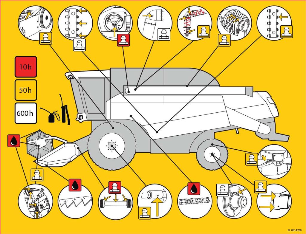
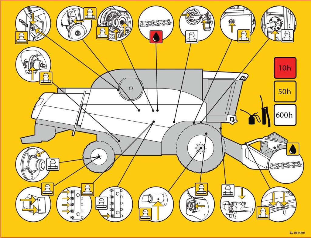
134 LUBRICATION DIAGRAMS T1 T2 132
135 SUMMARY OF PERIODICAL MAINTENANCE PROCEDURES For more detailed instructions on engine adjustments and maintenance, see the engine manual. Daily: Every 300 working hours or yearly: Lubricate the points to be lubricated daily. Check the engine oil level. Check the purity of the radiator and the inlet screen. Check the radiator coolant level. Check the hydraulic oil level. Check the fluid and oil connections for leaks. Check the function of the alarm system. Check the condition of the cab air filter. Check the purity of the AC condenser. Check the condition and tension of belts visually. Check the chopper knives visually. Check the tightening of the wheel nuts/bolts first hour and then each 10 hours till 50 total hours. Check tension of variator drive belt. Change the engine oil and filter 500 hours Change the engine air filters. Lubricate the fan variator hub. Lubricate the pedal shafts (Oil). Lubricate the gear lever joints and bearings (Oil). Lubricate the engaging levers (Oil). Change the cab air filter. Check the fluid level in the battery. Check the hydraulic hoses visually. Check the engine intake air hoses and coolant hoses for leaks. Replace at least every 5 years. (Check when manufactured on the hose.) Every 600 working hours or yearly: Every 50 working hours: Lubricate all the points specified in the table. Check the battery fluid level. Clean the outer element of engine air filter. Clean the breathers on the hydraulic containers on the outside. Check the gearbox oil level. Check the oil level in the engine split gear. Check the oil level in the final drives. Check the oil level in the knife drive device. Check the oil level in the unloading angle gear (Closed unloading). Check the knife condition. Check the concave basic setting. Check the condition of the threshing equipment. Check the condition of the power transmission equipment. Check the tension of belts and chains. Check the operations of safety clutches. Check and clean the cab air filter. Check the tension of the grain elevator chain. Check the tension of the return elevator chain Check the tension of the crop elevator chain. Check the brake functions. Check the brake fluid level. Check the light functions. Check the tyre pressures. Lubricate the carrier at the bottom of the filling auger in the grain tank. Change the oil in the gearbox. Change the fuel filters. Change the oil in the engine split gear. Change the oil in the knife drive device. Change the oil in the unloading angle gear (Closed unloading). Lubricate the bearings on the left-hand side of the threshing cylinder and rear beater. Lubricate the bearings on the shaker shoe crankshaft. Change the hydraulic oil and filter. (Always before the harvesting season.) Lubricate the middle shaft of the stairs. Lubricate the wheel bearings. Grease the shaft gasket in the rear wheel hydraulic motor (on 4WD models, once a year; only a couple of pushes). Lubricate the hinges and lock on the cab door. Sensitize the friction plate type of safety clutches always before the harvesting season (feeding auger, crop elevator top shaft, grain elevator). Check the condition of the hydraulic hoses. Replace at least every 10 years. (Check when manufactured on the hose.) Every 1200 working hours or every other year: Change the oil in the final drives. Replace the breather valve in hydraulics. Replace the breather valve in fuel tank. Every other year: Change the radiator fluid in the engine. Change the brake fluid. 133
136 STORAGE WHEN NOT IN USE To guarantee the operating reliability of the combine, proper service and storage are of great importance. The service before winter storage can be divided into three parts, in order of performance: cleaning, checking and protection. A dry store or shed is ideal storage for the combine. Cleaning: Open the stone trap and all doors. Remove and wash all detachable guards, sieves, the bottom cassettes of the grain pan and straw walkers as well as the grain tank bottom augers. Dirt is efficiently removed from a dry combine by compressed air. A high-pressure washer may be used with caution. To reduce drying time use warm water and idle the threshing machinery. Do not direct water jets at the bearings, as the packing does not hold against a strong spray of water. In normal seasons, it is not necessary to wash the inner parts of the combine with water; the inside of the combine can be raked clean with a suitable tool. Apply suitable solvent on heavily greasy spots before washing. Start cleaning from the top. Clean the radiator cells by blowing air from the direction of the wings. Checking: Take a pen and paper and write down all the shortcomings and required service measures in the following order: Condition of the knives. Draw-in fingers and bearings. Slip damages and breaks in belts and the remaining tensioning margin. Condition of and basic settings for the cylinder and concave. Condition of the grain pan and shaker shoe packing. Bearing clearances and fastenings. Wear, corrosion and dents. Rotor knives and counter-knives of the chopper as well as rotor bearings. It is important to have the recorded defects repaired before storage to ensure the efficient functioning of the combine at the beginning of the following harvesting season. Protection: Use pure engine oil or special protective oil in a sprayer. Places to be protected: Knife (protective oil) Draw-in fingers (protective oil) Worn paint (paint) Electrical connections (special protective spray) Chains (oil); rotate the mechanism by hand to ensure even lubrication. Transmission chains (unloading and the reel) shall be disengaged, cleaned with a solvent and lubricated with molybdenic oil. Lubrication of the rotor knife joints of the chopper. After protection all the cleaning doors, the grain pan and straw walker bottoms and sieves are left open to produce a draught inside the combine. This will prevent rodents from nesting in the inner parts of the combine. Also leave the service door to the instrument panel open! Pre-storage Service of Cab Ventilation: Filters are cleaned. Air channels on the cab top and the ventilator unit with its cells are also cleaned. This may be done with a vacuum cleaner. 134
137 Pre-storage Service of the Air Conditioner: Use compressed air to clean the cooler condenser and evaporator cells. In case the combine engine is run during storage, the cooler should also be switched on for a few minutes. To operate the cooling system in cold weather, have the heater on at full capacity and the ventilator fan stopped for approx. 15 min. during which time the air conditioning sensor will warm up and enable the switching on of the compressor. After this the ventilator fan is run at its lowest speed and the cooling at full capacity. Pre-storage Service of the Engine: Clean the engine on the outside. Change the fuel filter. Change the engine oil. Change the engine oil filter. Drain and clean the fuel tank. Check the anti-freezing quality of the coolant. It must be a minimum of - 25 C. Run the engine min. 10 minutes. Seal the exhaust pipe, inlet opening of the air filter and the breather with e.g. masking tape or plastic film. Other Pre-storage Measures: Change the oil in the gearbox. Clean the magnet in the bottom plug and the breather filter. Clean the air filter. Disconnect the battery, the negative pole first, clean the top of the battery with warm water and store it in a dry cool place. Clean the cable lugs and apply grease to them. It is not necessary to remove or loosen the V belts for storage. Check the tyre air pressure. Lubricate all points to be lubricated and run the threshing machinery after that. Lower the cutting table and the pick-up reel to allow the cylinder pistons to go in. After-storage Attention Remove the engine opening covers. Fit new air filters (engine and cab). Fasten the fully charged battery, the positive pole first. Check the coolant level. Change the hydraulic oil and filters. Check the oil levels in the engine and the gearbox. Check the belt and chain tensions. Make sure the rotor knives of the chopper turn. Turn the coolant pump by the fan to loosen a possibly stuck sealing. Open slightly the bottom plug of the fuel tank and drain any condensed water from the tank bottom. Run the engine on the starter a few revolutions with the stopper in the stop position or with the running solenoid cable disconnected to allow oil pressure into the bearings prior to the actual starting. Check that there are no foreign objects inside the combine. Start the engine and let it run on fast idle for about 3 minutes. Watch the oil pressure and alternator control lights. Check for any coolant, oil or fuel leaks. Carefully engage the threshing mechanism. Gradually raise the RPM to the normal level, simultaneously monitoring the function of the threshing mechanism. Stop the threshing mechanism and the engine and close all doors. Set the threshing settings for the first threshing. 135
138 RECOMMENDED TOOLS AND ACCESSORIES Recommended Tools For do-it-yourself maintenance it is necessary to replenish the tools supplied with the combine with the special tools mentioned under Maintenance as well as with the fork, ring and socket wrench kits, observing the wrench gap table below and the wrench gaps of 16, 18 and 27 mm for the hose and pipe couplings. Recommended Accessories For the Knife Device Knife sections 25 pcs Knife plate screws 50 Fingers 2 Knife holders 2 For the Table Auger: Fingers 8 pcs Finger bearings 4 Bearing holders 2 For the Reel: Plastic tines 5 pcs General Parts Hexagonal screws M6-M12, the most common lengths of mm, strength class minimum 8.8. Hexagonal nuts M6-M12, strength class 8. A few locknuts. Washers and spring washers, mm. Plate screws 4.8, lengths mm. Split cotters 3x20 and 5x30 mm. Wire cotters 2.5x50 mm. Spring cotters, 3-8 mm, lengths mm. Circlip cotters 10 mm. Grease nipples 6 mm and 1/8, straight and angled. Additional loops for chains. Fuses 7.5, 15, 20, 25 and 50 A. SCREW JOINTS It is important to tighten the screw joints into the correct tightening torque. Wrench gaps and torque for the screws: Screw Wrench Torque for screws size gap mm of 8.8 strength class M Nm M M M M M M Note! Torque for fixing screws in the wheels: Front wheels M Nm Rear wheels M Nm Rear wheels 4WD M Nm 136
139 DISCARDING OF THE COMBINE Even the best of products will come to the end of its useful lifetime and it is time to discard it. It is important to make sure the discarded combine will not be harmful to the environment. Below you will find a list of things to consider before discarding the combine: Do not let the discarded combine spoil the scenery. Store it indoors. Lower all the hydraulically raised parts of the combine. (Cutting table, reel, unloading pipe) Remove the battery and take it to an appropriate problem waste collection centre. Drain all the fuel into a spare tank. Drain all the oil from the engine, gearbox, final drives, engine split gear, knife drive device and hydraulic systems into an appropriate collection dish. Drain the oil from all the pipes, cylinders and hydraulic components. Drain the coolant into a collection dish. If the combine is equipped with air conditioning, let an authorised service outlet drain the cold gas and oil. If the combine is to be scrapped, follow the below given procedure: Disassemble the combine starting from the top. In case flame cutting or other spark generating measures are used, pay careful attention to fire precautions. There may be highly flammable dust and grease in the combine structure. Beware of any moving machine parts. Most of the combine material is steel. There is copper in the radiator and electric conductors, start-up motor and alternator. There is rubber in the tyres, belts and hoses. There is plastic in the crop elevator tines, cab interior, lamps and lights. Pay attention to the recyclability of the components. There is glass in the cab, mirrors, lamps and lights. There is no asbestos in the combine structure. There are minor quantities of heavy metals, such as lead in the slide bearings. Take all the recyclable parts to a recycling centre. 137


140 CONVERSION TO MAIZE HARVESTING When the combine is used to thresh maize, it can be fitted with a 4- or 6-row maize header. Note! It is very important that row distance in the header and the row distance on the field are almost the same Some other modifications are also required to make the combine suitable for threshing of maize. If the combine is equipped with pre-threshing cylinder you need maize parts also for pre-threshing unit.! Maize kit for the combine (option) includes all necessary parts for maize harvesting. The instructions are based on a combine equipped with the following components: 3-4 table lifting cylinders A cylinder drive variator in the speed range of r/min (low speed kit) A HD (maize) concave V1 Fitting of the Maize Header Remove the cereal-cutting table from the crop elevator and replace it with the maize header. There may be a drive shaft on both sides of the table, particularly if the table is equipped with a stubble chopper. If this is the case, remove the shield plate from the end of the transmission shaft cover on the right-hand side of the crop elevator and connect the right-hand side shaft. Disconnect the electric connector from ON/ OFF cartridge A of the pick-up reel control valve, fig. V3. It is located on the left-hand side of the combine, below the engine. V3 Do not use the cereal-cutting table to thresh maize. 138

141 Modification of the Threshing Cylinder Make sure the HD concave has been fitted. Fit the stone trap blanking plate A, fig. V4. The plate is fixed with the same bolts as the lower sealing of the crop elevator. Installation is done through the opened stone trap. The plate rear lies on top of the front of the concave. Same blanking plate is used also for combine equipped with prethreshing unit Fit rubber shield plate B, fig. V4. This is necessary, particularly if there is a stubble chopper on the maize header. Fixing with the same bolts as the before mentioned shield plate and sealing plate. Same rubber shield plate is used also for combine equipped with pre-threshing unit B A V4! Fit filler plates A, fig. V5, between the cylinder rasp bars. Use DIN bolts with locking glue. The tightening torque of the bolts is Nm. To facilitate the job, open the front door to the cylinder chamber and the top door to the crop elevator. Note! The narrower edge of the filler plate (marked with a hole) shall be against the cylinder rasp bar! Note! Never use higher than 900 RPM cylinder speed with the filler plates fitted. Note! The stone trap blanking plate and cylinder filler plates shall be removed when threshing cereal. V5 A 139
142 Other Modifications of the Threshing Mechanism: Fit the return auger blanking plates fig. V7, to the rear of the shaker shoe. This is needed especially when harvesting in damp conditions. Keep the return auger running even with the blanking plate fitted. Fit guide plate, fig. V8, to the straw hood. The plate prevents the cobs from getting to the rising side of the rotor blades and decreases the risk of the cobs being thrown upwards. The guide plate is required if the chopper is used. Note! Never use the above mentioned plate with any other plants but maize. Fluffy straw may get arched on the plate. V7 Rear Weights Std threshing unit The need for rear weights depends on the combine type and what kinds of accessories and cutting table are used. The main principle is that 20% of the total weight rests on the rear axle. Use of extra weights is not recommended with cereal header Approximately 760 kg of additional weight is required on a combine with standard threshing mechanism (with the weight of the maize header 2130 kg). The weights of the following accessories can be subtracted from this weight. - straw chopper 280 kg - straw guide (no chopper) 150 kg - chaff spreader 70 kg - 6.3m 2 straw walkers 100 kg - 4 WD 100 kg V8 Fit rear weight frame, fig. V9, to the rear beam. Place a maximum of twelve additional 36-kg weights on the frame. The maximum weight to be gained is 450kg. It is possible to install max three weights (27 kg each) onto the straw guide (when no straw chopper). They will cause 40 kg weight to rear axle each. Additionally, the rear tyres can be filled with either water or saline solution (Calcium chloride) to gain an additional 190kg. TS-model The TS model equipped with a pre-cylinder does not require additional weights. V9 140

143 Modifications of the Chopper (if used with maize): Turn the chopper counter knife unit to its bottom position. Fit guard plate, fig. V10, on top of the counter knives. V10 Remove the two rear-most chopper belts off the cock wheel and cock wheel, fig. V11. Remove the belt pulley from the shaft trestle and fit it the other way. (With the bigger pulley outwards) Refit the pulley unit so that the shaft is in the fore-most position. Fit the belts and tension to their original tension. This will decrease the chopper speed to 2000 RPM. V11 Special Instructions to Be Followed when Threshing Maize 1 Crop Elevator Adjust the bottom shaft of the crop elevator near its top position. 2 Adjustment of the Concave If the combine is equipped with pre-threshing cylinder, adjust the pre-concave clearance fully open mm from the front in compliance with the instructions given under Approximate Settings The suitable concave clearance depends on the moisture and size of the corncobs. Adjust the clearance and cylinder speed so, that you will get all the grains removed from the cobs without damaging the grains. The core of the cob should also be undamaged; it must not split on the cylinder. When these conditions are met, threshing is at its most efficient. If the core splits, there are unthreshed grains on it. The concave adjustment ratio shall be in position 1.5:1 or 1:1. See instructions in section Threshing Equipment, fig. L19. If necessary, the adjustment ratio can be tuned using the support bars on the concave. 141
144 Check the threshing result on the straw walkers before the chopper. Remember to return the concave clearance back to normal before starting cereal harvesting. 3 Harvesting in Freezing Conditions Remember to clean the grain elevator and the grain augers daily after threshing. If this is not done, they may be frozen the next morning, which will damage them. Modification back to Cereal Harvesting: When modifying the combine back to cereal harvesting, any special parts and components shall be replaced with the original ones intended for cereal harvesting. However, the rear weight frame (without the weights) may stay. Remember to adjust the concave back to normal before moving cereal harvesting. 142
145 THRESHING EQUIPMENT TO BE USED WITH SUNFLOWER No special threshing equipment is necessary when harvesting sunflower. The basic cutting table can, however, not be used with sunflower. The seeds fall off easily and the whole flower heads may fall onto the ground in front of the knife. This would mean too high table losses. The combine may be equipped with a special cutting table meant for sunflower. This is recommendable if there are hundreds of hectares to be threshed annually. A less expensive solution is to provide the standard cereal-cutting table with sunflower equipment. Fit extension trays in front of the knife to guide the stems onto the cutting knife and prevent seeds and flower heads from falling onto the ground. The reel tines are equipped with plates by means of which any flower heads on the trays are fed in. The straw dividers are replaced with high plate guides at the ends of the table to prevent the plants from turning to the side on top of the table end. Fitting of Sunflower Equipment to the Cereal Table Tray Clamps If the sunflower equipment has not been pre-installed in the factory, fit the tray clamps to the cutting knife. The clamps go in the gaps between the knife presses. See fig. V21. Screen plate A is fitted above the knife and hook B below the knife. The first clamp goes between the 6 th and 7 th finger. M10x45 screws are used in the fitting. V21 Fitting of the Side Guides The side guides are fitted to the same clamps as the straw dividers, fig. V22. V22 143
146 Fitting of the Trays The center trays are fitted using the quick coupling next to each clamp. Adjust the tightness of the quick coupling when doing the installation, Fig V23 The outer trays are fitted at their ends to the side guide with screw D, fig. V22. The rear end is fixed with screws A, fig. V22 to the end of the table. Drill screw holes in the table. The height of the side tray rear is the same as that of the center trays. V23 Fitting of the Pick-up Reel Plates Guard plates are fitted to the pick-up reel tines behind the tines. Fig. V24. Each plate is fixed with five screws A to the blade pipe (and with five bindings to the tines if needed). V24 144


147 SPECIAL INSTRUCTIONS TO BE FOLLOWED WHEN THRESHING RICE General Rice can only be threshed using a combine originally equipped for this purpose. Rice is extremely heavy to thresh, so the combine must be equipped with a heavy-duty table auger and crop conveyor mechanism. Use a replaceable type of rear beater equipped with wings. It is advisable to have a 4-WD transmission in the combine. Before starting to thresh rice, the combine is fitted with a suitable spike tooth threshing cylinder and concave. The rear beater is fitted with spiked wings instead of plate wings. The straw walkers are equipped with additional ruffle plates. Modifications on the threshing cylinder To gain access to the threshing cylinder, disengage the crop elevator from the combine. Disengaging of the Crop Elevator (with the Cutting Table Fitted) - Disconnect the hydraulic hoses from the table on the right-hand side. - Disconnect the electric cables on the cutting table. (Fig. Y1) Y1 - Remove the left-hand guard. (Fig. Y2) Y2 145


148 - Support the crop elevator from below using e.g. a lockable lifting jack as shown. (Fig. Y3) Y3 - Disconnect hydraulic hose connection A to reduce pressure in the cutting table lifting cylinders. Remove carrier pins B in the table lifting cylinders from the crop elevator. (Fig. Y4) Y4 - Slacken table drive belts A by turning adjusting screw B. Remove the table belts from the crop elevator. (Fig. Y5) Y5 146
 - Reverse the combine slowly to disengage the crop elevator and the table from the combine.")
 and a lockable support to lift the front axle. (Fig.")

149 - Remove the carrier pins from the crop elevator. (Fig. 6) - Reverse the combine slowly to disengage the crop elevator and the table from the combine. Keep in mind that the crop elevator is heavy and needs to be well supported before the combine is reversed! Y6 Removing of the Cylinder Variator - Use a jack (10 tons) and a lockable support to lift the front axle. (Fig. Y7) - Remove the right-side front tyre (bottom figure). - Remove the right-side mudguard. Ensure that the front axle is properly supported to stop the combine from overturning. A jack must not be used to support the front axle as it is only intended for lifting. Y7 - Slacken nut A until the spring pack loosens. (Fig. Y8) Y8 147
 Y9 - Loosen 3 screws A and remove the")

 - Slacken the pulleys and the belt on the")
150 - Undo nuts A to slacken the variator belt. (Fig. Y9) Y9 - Loosen 3 screws A and remove the locking plate and loosen nut B, (fig. 10). Y10 - Loosen screws A connecting the variator arms and remove the arms. (Fig. Y11) - Slacken the pulleys and the belt on the cylinder variator. Y11 148

 - Remove the wedges off the threshing cylinder shaft. - Lock the cylinder with wooden wedges. (Fig.")

151 Disengaging of the Cylinder With the crop elevator and the cylinder variator removed as above. Y12 - Set the concave in its top-most position. - Remove the speed indicator sensor and its bracket on the left side. - Remove the bearing locking ring, loosen the bearing fixing screws and remove the bearing. (Fig. Y12) - Remove the wedges off the threshing cylinder shaft. - Lock the cylinder with wooden wedges. (Fig. Y13) Y13 - Loosen the bearing locking screws on the right side and pull the shaft with its bearing housings out from the right side. Fig. Y14 - Put two 3-metre planks from the floor to the edge of the concave and roll the cylinder onto the ground. Note! The threshing cylinder is heavy. This job requires two people. Y14 149


152 Removing of the Concave Fig. Y16 - Set the concave in its lowest position. - Loosen lowest nuts A. - Remove cotter B and slacken locking screws C. - Remove the concave brackets on both sides of the combine. Y16 - Pull the concave supporting shafts out to the right. - Pull the concave out from the front. Y17 Fitting of the Rice Concave Fitting is done in reverse order. Pay attention to the following points: - Push the concave in from the front. Note! The concave extension shall be fitted with the ratio adjustment plate in position 1:1. (The plate in position C, fig. L19a.) - Push the concave supporting shafts in. - Fit the concave brackets. - Fit the cotter and tighten the locking screws. Note! Concave adjustments are made after the spike tooth cylinder has been fitted. L19a 150
 by tightening the screws. Tightening torque for the screws is 45Nm. Note!")

153 Replacing of the Rear Beater Wings Fig. Y18 - Remove all the 6 wings by loosening the 48 screws. - Fit the spiked wings (3+3) by tightening the screws. Tightening torque for the screws is 45Nm. Note! The left and the right side spiked wings shall be fitted alternately. Removing of the Forward Baffle Remove forward baffle A and its supporting shaft B behind the rear beater. Fig. Y19 Access to the straw walker compartment is through the top door. Y18 Y19 151
 - Fit the left side bearing, but do not lock the bearing yet.")
.")
154 Fitting of the Spike Tooth Cylinder - Replace the rear beater wings (separate instructions). - Fit the rice concave (separate instructions). - Push the spike tooth cylinder along planks to its place. - Lock the threshing cylinder with wooden wedges. - Push the cylinder shaft with its bearings to its place from the right side. (Fig. Y20) - Fit the left side bearing, but do not lock the bearing yet. - Tighten the fixing screws in the right-hand bearing. - Tighten the screws in the left side bearing and lock the eccentric ring. - Center the spike tooth cylinder sideways so that the space between the spikes on the cylinder and the rear beater is equal on both sides of the spikes (bottom figure). - Lock the cylinder shaft wedges in place. - Fit the speed indicator sensor and its bracket, (bottom figure). - Adjust the sensor distance from the disc (max. 1 mm) - Refit the cylinder variator pulleys. Settings for the variator arms and belt are given in the combine service manual. Y20 Basic Setting of the Concave - Set the concave in position 17 mm in the cab. - Set rice concave and spike tooth cylinder distance X at 17 mm next to the second and the last spike row on the concave. (Fig. Y23) Height adjustment is made with screws A. (Fig. Y16) - Adjust the concave sideways by tightening or loosening adjustment screws so that the space between the concave and the cylinder spikes is equal on both sides of the spikes. (Fig. Y22) - Lock the adjustment screws by tightening the locking nuts. Y22 Y23 152

155 Setting Instructions for the Cutting Table - Clearance between the table auger and the bottom of the cutting table is 5 mm. - Clearance between the anti-wind plates and the table auger is 2 3 mm. Fitting of the Ruffle Plates in the Straw Walkers Additional ruffle plates can be fitted to the straw walkers both at the rear of the stairs and to the sieve surface in the middle of the straw walker. The maximum number of ruffle plates recommended as given in the table. (Fig. Y25) Y25 Special Instructions for Rice Threshing A spike tooth threshing cylinder necessary when threshing rice does not separate grains as efficiently as the standard cylinder. This means that more grains go onto the straw walkers to be separated. Another difficulty is separating grains from dense green foliage. For these reasons threshing efficiency with rice is lower than with wheat. Aim at even feed. Threshing losses are highest at load peaks. The longer the stubble the more efficiently the combine threshes. Efficiency depends mainly on the amount of straw. Set the cutting table auger low enough (clearance from the bottom approx. 5 mm). Set the anti-wind plates behind the auger at a distance of 2-3 mm from the auger. Make sure the separating surfaces are clean. The spiked concave, straw walkers and sieves are the most important. Set the cylinder rotation speed low enough in order not to damage the grain husks. However, do not set the speed too low as lower rotation speed reduces threshing efficiency. The spiked concave has spikes in five rows. Different conditions and types of rice require different threshing. Too aggressive threshing produces too much chaff, which reduces straw walker efficiency. As factory setting only every other spike has been fitted to the front-most spike row. The missing spikes are supplied loose with their nuts to be fitted if required by the conditions. The number of spikes in the rear-most row can be halved or all of them can be removed if desired. Tightening torque for the spike fixing screw is 160Nm and for the locking nut 100 Nm. Set the fan speed high enough to ensure a clean threshing result. Conversion back to Cereal Threshing When going back to threshing cereal or maize, all the cylinder modifications shall be returned to their original state. Do the job in reverse order. The straw walker ruffle plates may also be used with cereal, but must be removed when threshing maize. 153
Comia. Combine Harvester Instruction Book. Sampo Rosenlew Ltd P. O. Box 50 FIN PORI FINLAND /2017 Englanti
 Comia Combine Harvester Instruction Book Sampo Rosenlew Ltd P. O. Box 50 FIN-28101 PORI FINLAND 0814374 01/2017 Englanti THIS BOOK The purpose of this book is to enable the Operator to handle and maintain
Comia. Combine Harvester Instruction Book. Sampo Rosenlew Ltd P. O. Box 50 FIN PORI FINLAND /2018 Englanti
 Comia Combine Harvester Instruction Book Sampo Rosenlew Ltd P. O. Box 50 FIN-28101 PORI FINLAND 0815601 4/2018 Englanti THIS BOOK utmost importance that the Operator becomes familiar with the structures,
Combine Harvester Instruction Book. Sampo Rosenlew Ltd P. O. Box 50 FIN PORI FINLAND /2016 Englanti
 2035 2045 2065 2085 2095 Combine Harvester Instruction Book Sampo Rosenlew Ltd P. O. Box 50 FIN-28101 PORI FINLAND 0814334 02/2016 Englanti THIS BOOK utmost importance that the Operator becomes familiar
8-XP Combine Harvester Instruction book
 8-XP Combine Harvester Instruction book Sampo Rosenlew Ltd P.O.Box 50 FI 28101 PORI, FINLAND 11/2012 0814418 This book The purpose of this book is to enable the Owner/Operator to handle and maintain the
John Deere. MODEL: 4400 Combine JD-O-OMH86804
 John Deere MODEL: 4400 Combine THIS IS A MANUAL PRODUCED BY JENSALES INC. WITHOUT THE AUTHORIZATION OF JOHN DEERE OR IT'S SUCCESSORS. JOHN DEERE AND IT'S SUCCESSORS ARE NOT RESPONSIBLE FOR THE QUALITY
productive harvesting subtle power pioneer in cleaning careful separation advanced driving ergonomics
 productive harvesting Efficient cutting table for improved productivity subtle power Same power, less fuel consumption pioneer in cleaning Market s easiest and fastest combine to clean careful separation
Wheel Horse. 44 Snowthrower. for 5xi Lawn and Garden Tractors. Model No & Up. Operator s Manual
 FORM NO. 8 Rev A Wheel Horse Snowthrower for 5xi Lawn and Garden Tractors Model No. 7966 890050 & Up Operator s Manual IMPORTANT: Read this manual, and your tractor manual, carefully. They contain information
6.0 Vehicles and machinery
 Code of Practice for Preventing Injury and Occupational Ill Health in Agriculture 6.0 Vehicles and machinery 6.1. Risk assessment Farm vehicles and machinery account for the highest proportion of farm
9895 Combine Parts Catalog EFF. S/N HSC8101
 9895 Combine Parts Catalog EFF. S/N HSC8101 1 FORWARD ALPHABETICAL INDEX The complete alphabetical index appears at the beginning of this publication. It is used to locate major groups, assemblies and
Combine harvesters CROP TIGER
 Combine harvesters CROP TIGER 40 30 Threshing system and engine. Efficient drive power: TATA engine (emissions standard BS III) with up to 76 hp and high reserves of torque thanks to greater power at low
MODELS 1324 & 1624 & 1824
 THE MODELS 1324 & 1624 & 1824 HYDRAULIC TRENCHERS CONGRATULATIONS! You are now the proud owner of a BARRETO trencher. Please take a moment of your time to look over the following information. Familiarize
Emergency response guide
 Emergency response guide 20408 DAF Trucks N.V., Eindhoven, The Netherlands. In the interest of continuing product development, DAF reserves the right to change specifications or products at any time without
LEXION Demands rise.
 LEXION 770 760 750 740 730 670 Demands rise. LEXION 770 / 770 TT 760 / 760 TT 750 / 750 TT 740 / 740 TT 730 670 Straw Walker Threshing system APS (Accelerated Pre-Separation) MULTICROP concave Drum width
Emergency response guide
 Emergency response guide ΛΦ 20426 DAF Trucks N.V., Eindhoven, The Netherlands. In the interest of continuing product development, DAF reserves the right to change specifications or products at any time
Finishing Mower Estate 72
 Finishing Mower Estate 72 Owners/Operators Manual & Spare Parts List Issue Date: October 2011 1 Introduction Your FIELDMASTER Estate 72 Finishing Mower has been designed to do a range of work to your satisfaction.
FR 28 Forwarder instruction manual
 FR 28 Forwarder instruction manual Sampo Rosenlew Ltd P.O.Box 50 FI 28101 PORI, FINLAND 06/2017 0812481 Englanti Introduction The purpose of this book is to familiarize the operator with the forwarder.
STIGA TORNADO 51 S 51 SE PRO 51 S
 STIGA TORNADO 51 S 51 SE PRO 51 S 8211-0225-09 SVENSKA S 1 2 3 1. 2. ADD FULL FULL ADD ADD FULL 0,15 l. 3. LS 45 4. XTE 60 3x 5. LS 45 6. XTE 60 STOP I H 7. 8. 2 S SVENSKA 9. 10. 11. 12. LS 45 0,75 mm
1.CONTENTS 1. Contents Control location Before riding Safe riding Driving Use genuine spare parts Use
 1.CONTENTS 1. Contents... 1 2. Control location... 3 3. Before riding... 4 4. Safe riding... 4 5. Driving... 5 6. Use genuine spare parts... 5 7. Use of each component... 6 Gauges... 6 Operation of ignition
MOTORINI GP 50. User s Manual.
 MOTORINI GP 50 User s Manual www.motorini.co.uk Dear user: Thank you for choosing to buy a Motorini GP 50 This manual provides the correct operation and maintenance methods for safe riding and maintaining
PCBL 1600/1800 POWER WHEELCHAIR MODERN USER'S MANUAL Edition
 PCBL 1600/1800 POWER WHEELCHAIR MODERN USER'S MANUAL Edition 09.2013 mdh sp. z o.o. 90-349 Łódź, ul. Tymienieckiego 22/24 tel. (+48) 42 212 32 08 fax: (+48) 42 674 04 99 www.mdh.pl viteacare@mdh.pl 1 TABLE
HANDLING BIG BALES SAFELY
 HANDLING BIG BALES SAFELY PRE-HARVEST PRECAUTIONS Those big round bales weigh 1,000 to 2,000 pounds. Developing safety awareness begins with the operator's manual. Take time to read through it when the
Emergency response guide
 Emergency response guide 2047 DAF Trucks N.V., Eindhoven, The Netherlands. In the interest of continuing product development, DAF reserves the right to change specifications or products at any time without
User Manuel. Titan Hummer XL
 User Manuel Titan Hummer XL Dear User, Tzora Active Systems Ltd. thanks you for choosing the Titan Hummer-XL and wishes you safe and enjoyable journeys. For proper operation and to maintain the scooter
D. Instruments and controls
 Operating instructions for the extra and alternative equipment are in section K, of this book, after each extra equipment. D. Instruments and controls NOTE: The places of the switches can vary depending
AU DU PONT DE LUTTRE BRUSSELS BELGIUM PHONE: FAX: OPERATING MANUAL. Electric Fully Automatic Floor Saw FS 1218 EX
 AU DU PONT DE LUTTRE 74-1190 BRUSSELS BELGIUM PHONE: 322 34 83 162 FAX: 322 34 83 136 OPERATING MANUAL Electric Fully Automatic Floor Saw FS 1218 EX 2 Important information before you start! When the machine
Wheel Horse. 36 Tiller. Model No & Up. Operator s Manual
 FORM NO. 8 9 Rev. A Wheel Horse 6 Tiller for Classic Garden Tractors Model No. 7970 690000 & Up Operator s Manual IMPORTANT: Read this manual carefully. It contains information about your safety and the
WILDFIRE OPERATOR TRAINING MANUAL
 WILDFIRE OPERATOR TRAINING MANUAL 1 WildFire Component Locations Turn Signal Switch Accessory Switch Panel Generator Start/Stop Switch and Hour Meter Fig. 1 Brake Pedal Gas Pedal 2 WildFire Component Locations
Package Contents Part A (3) I-Beam (1) Base (2) Other parts
 I-Beam (1) Base (2) Other parts") Page 1 Installation Instructions for 81245 Adjustable Height Gantry Crane 1-Ton Capacity Table of Contents Important Safety Information pg. 2 Specific Operation Warnings pg. 2 Main Parts of Product pg.
Page 1 Installation Instructions for 81245 Adjustable Height Gantry Crane 1-Ton Capacity Table of Contents Important Safety Information pg. 2 Specific Operation Warnings pg. 2 Main Parts of Product pg.
610 BUSHEL MANURE SPREADER
 610 BUSHEL MANURE SPREADER RODA MANUFACTURING 1008 LOCUST ST. HULL, IA. 51239 Art s-way Manufacturing 712-439-2366 Co., Inc. Hwy 9 West - PO Box 288 WWW.RODAMFG.COM Armstrong, IA. 50514 U.S.A 2 INTRODUCTION
OPERATIONS MANUAL LEVER CHAIN HOIST
 OPERATIONS MANUAL LEVER CHAIN HOIST IMPORTANT SAFETY INFORMATION Please read, understand and follow all safety information contained in these instructions prior to the use of this hoist. Retain these instructions
REPAIR MANUAL AFX8010
 REPAIR MANUAL AFX 1 27/05/2004 Contents INTRODUCTION DISTRIBUTION SYSTEMS POWER PRODUCTION POWER TRAIN TRAVELLING BODY AND STRUCTURE TOOL POSITIONING CROP PROCESSING A B C D E G K AFX 1 27/05/2004 INTRODUCTION
SECTION 1 7 OPERATION OF INSTRUMENTS AND CONTROLS Ignition switch, Transmission and Parking brake
 SECTION 1 7 OPERATION OF INSTRUMENTS AND CONTROLS Ignition switch, Transmission and Parking brake Ignition switch.............................................. 114 Automatic transmission.....................................
JAGUAR. Post Harvest Check
 JAGUAR Post Harvest Check TABLE OF CONTENTS Introduction Handling... 4 Checklists Cab / Operator's platform... 7 Electric system... 9 Feeder unit... 10 Chopping... 12 Discharge... 14 Gearbox... 17 Chassis...
Boring Unit Sitework Systems Attachment
 FORM NO. 6 Boring Unit Sitework Systems Attachment Model No. 0 89000 & Up Operator s Manual English (CE) Contents Page Introduction................................. Safety......................................
SIP Direct Drive Oil-Lube Air Compressors - Operating & Maintenance Instructions
 SIP Direct Drive Oil-Lube Air Compressors - Operating & Maintenance Instructions Please read and fully understand the instructions in this manual before operation. Keep this manual safe for future reference.
Backhoe for Dingo Compact Utility Loaders
 Form No. 50-5 Backhoe for Dingo Compact Utility Loaders Model No. 60 000000 & Up Operator s Manual Original Instructions (EN/GB) Contents Page Introduction................................. Safety......................................
HYDRAULIC PALLET TRUCK. MODEL No: PTE550 PART Nos OPERATION & MAINTENANCE INSTRUCTIONS
 HYDRAULIC PALLET TRUCK MODEL No: PTE550 PART Nos 7630171 OPERATION & MAINTENANCE INSTRUCTIONS 0604 Please read these instructions carefully before operating the truck Thank you for purchasing this CLARKE
OPERATION AND MAINTENANCE MANUAL SERIES HIGH GRASS MOWER FT
 S.p.A. OPERATION AND MAINTENANCE MANUAL SERIES HIGH GRASS MOWER www.hscmsc.co.uk CONTENTS INTRODUCTION IDENTIFICATION AND TECHNICAL CHARACTERISTICS PACKING AND TRANSPORT SAFETY RULES AND LIMITS ON USE
Commander 15i Container and Pallet Loader. Property of American Airlines
 Commander 15i Container and Pallet Loader Section 2. Operation BEFORE ATTEMPTING TO OPERATE OR MAINTAIN THE VEHICLE, COMPLETELY READ AND UNDERSTAND THE OPERATION AND MAINTENANCE MANUAL, INCLUDING ALL DANGER,,
General Knowledge Test E
 General Knowledge Test E 1. If you are convicted of a traffic violation you should notify your employer within thirty (30) days if the following are true: a. The violation occurred in your personal vehicles.
Twin Master Combine. Threshing Cylinder Section 1. Threshing Cylinder ( ) Threshing Cylinder (2009 Present)...
 Threshing Cylinder (2009 Present)...") Threshing Cylinder Section 1 Threshing Cylinder (2006 2008)... 2-8 Threshing Cylinder (2009 Present)... 9-15 Return to this page by clicking the upper right corner of any page in this section. Revised
Threshing Cylinder Section 1 Threshing Cylinder (2006 2008)... 2-8 Threshing Cylinder (2009 Present)... 9-15 Return to this page by clicking the upper right corner of any page in this section. Revised
SAFETY GUIDANCE MATERIAL
 SAFETY GUIDANCE MATERIAL SAFETY OPERATIONS GUIDANCE MONDAY MARCH 23, 2015 This safety resource was written for the scrap industry by the scrap industry and was developed to assist you in making your scrap
Disc Grinder PDA-100H. Handling Instructions. Read through carefully and understand these instructions before use.
 Disc Grinder PDA100H Handling Instructions Read through carefully and understand these instructions before use. 1 2 4 6 8 1 2 3 4 5 6 7 9 0 8 L K I G 1 3 5 7 15 ~30 A B 1 A D 5 9 8 B C 0 1 2 J 4 5 8 0
SECTION 1-6 OPERATION OF INSTRUMENTS AND CONTROLS 05 HIGHLANDER_U (L/O 0409) Gauges, Meters and Service reminder indicators
 Gauges, Meters and Service reminder indicators") SECTION 1-6 OPERATION OF INSTRUMENTS AND CONTROLS Gauges, Meters and Service reminder indicators Fuel gauge................................................ 132 Engine coolant temperature gauge...........................
SECTION 1-6 OPERATION OF INSTRUMENTS AND CONTROLS Gauges, Meters and Service reminder indicators Fuel gauge................................................ 132 Engine coolant temperature gauge...........................
PCBL 1610/ 1810 DE LUXE POWER WHEELCHAIR USER'S MANUAL Edition
 PCBL 1610/ 1810 DE LUXE POWER WHEELCHAIR USER'S MANUAL Edition 08.2010 mdh sp. z o.o. 90-349 Łódź, ul tymienieckiego 22/24 tel. (+48) 42 212 32 08 fax: (+48) 42 674 04 99 www.mdh.pl export@mdh.pl 1 TABLE
Farming machinery (1) Operation of ride-on tractors
 Operation of ride-on tractors") Farming machinery (1) Operation of ride-on tractors Tractors refer to a special type of vehicles that have an independent motor, can move without relying on rails, and can tow objects. The uses and types
Farming machinery (1) Operation of ride-on tractors Tractors refer to a special type of vehicles that have an independent motor, can move without relying on rails, and can tow objects. The uses and types
Edition Manual Chapter Page Workshop Manual, Stiga Park 5 Belts 11
 2008-05-19 Workshop Manual, Stiga Park 5 Belts 11 Pro 20 1. Dismantle the belts A and B as described above. 2. Block up the rear frame and remove the right rear wheel. Clean carefully the insex hole in
DRIVER S GUIDE. For VEHICLE INSPECTIONS
 DRIVER S GUIDE For VEHICLE INSPECTIONS The United States Laws and Federal regulations published herein are in public domain. Due to the constantly changing nature of government regulations, it is impossible
Auger Dingo Attachment
 Form No. 334-5 Auger Dingo Attachment Model No. 400 0000000 & Up Operator s Manual English (CE) Contents Page Introduction................................ Safety..................................... Safety
Section 4.3. Machine Operation - Operating Procedures. Before Starting the Engine: General Pre-Start Inspection
 Section 4.3 Machine Operation - Operating Procedures Before Starting the Engine: General Pre-Start Inspection... 4.3.2 Engine Starting Procedure... 4.3.2 Cold Weather Start-Up... 4.3.3 Engine Shutdown
Retro it Steering Column
 Retro it Steering Column INSTALLATION INSTRUCTIONS for 1976-86 CJ5 & CJ7 FOR PART NUMBER S: 1520800010, 1520800020, 1520800051, 1526800010, 1526800020, 1526800051 S I NCE 1986 Instruction # 8000000010
B2 Car and it s handling
 1 / 21 CAR AND IT S HANDLING Dashboard Pedals Gears Parking brake Climate control Windscreen wiper Driving lights and indicators Meters Initial preparation Driving Engine and refueling B2 Training -material
DYNAPAC CONCRETE EQUIPMENT RAMIRENT. BG70 Power Floats INSTRUCTIONS & SPARE PARTS CATALOGUE BG70 - IS ENG
 DYNAPAC CONCRETE EQUIPMENT INSTRUCTIONS & SPARE PARTS CATALOGUE BG70 Power Floats BG70 - IS - 10682 - ENG SAFETY INSTRUCTIONS - MACHINES SUBMITTED : Powered with : Electric, Pneumatic, Petrol or Diesel
TUFF TORQ TRANSAXLE. Tuff Torq Hydrostatic Transaxle. Transaxle Removal Tuff Torq
 Tuff Torq Hydrostatic Transaxle Internal Service 3. Disconnect the cotter pin and the washer to the brake rod (Figure 63). Internal service information is contained in the Tuff Torq KGIA Transaxle Service
HYDRAULIC PALLET TRUCKS
 HYDRAULIC PALLET TRUCKS HYDRAULIC PALLET TRUCKS MODEL Nos: PT550 GAL & PT685 GAL PART Nos: 7630234 & 7630236 OPERATION & MAINTENANCE INSTRUCTIONS 0204 Please read these instructions carefully before operating
Dead zone. Concave. Separation zone Concave sections. Concave whip Rotor whip 3
 Combine» RT490 ~ Versatile RT490 ~ The RT490 is a new 490 hp Class VIII combine from Versatile. True to the heritage of Versatile, the RT490 was designed to be rugged, reliable and simple to maintain and
2006 Machinery Operation Exam Kansas Hazardous Occupation Training
 2006 Machinery Operation Exam Kansas Hazardous Occupation Training Student Name: Date: Instructor: A passing score of 75% is recommended for the written exam, meaning the student must get at least 38 questions
QT INSTRUCTION MANUAL
 QT INSTRUCTION MANUAL PLEASE READ BEFORE USE Distributed by Qpod Motor Company Tel: 01404 850545 Fax: 01404 851110 www.qpod.co.uk Contents Pg 3 Servicing and Warranty Pg 4 Serial Numbers / Vehicle Keys
2014 Axial Combine Settings Guide
 2014 Axial Combine Settings Guide 1 DROPPING WINDROW SPREADING DISCHARGE DROPPING WINDROW SPREADING DISCHARGE DROPPING WINDROW SPREADING DISCHARGE Header Size DROPPING WINDROW SPREADING DISCHARGE DROPPING
SENTINEL R *331000* Sweeper Operator Manual. North America / International Rev. 05 ( )
") SENTINEL R Sweeper Operator Manual North America / International www.tennantco.com 331000 Rev. 05 (09-2008) *331000* This manual is furnished with each new model. It provides necessary operation and maintenance
SENTINEL R Sweeper Operator Manual North America / International www.tennantco.com 331000 Rev. 05 (09-2008) *331000* This manual is furnished with each new model. It provides necessary operation and maintenance
36 Tiller Wheel Horse Lawn and Garden Tractor Attachment
 Form No. 9 6 Rev B 6 Tiller Wheel Horse Lawn and Garden Tractor Attachment Model No. 797 890000 and Up Operator s Manual English(En) Contents Page Introduction................................ Safety.....................................
Part 1 OPERATION OF INSTRUMENTS AND CONTROLS
 Part 1 OPERATION OF INSTRUMENTS AND CONTROLS Chapter 1-6 Ignition switch, Transmission and Parking brake Ignition switch with steering lock Automatic transmission Manual transmission Four-wheel drive system
C6000 SERIES DEUTZ-FAHR C C6205 TS
 C6000 SERIES DEUTZ-FAHR C6205 - C6205 TS C6000 SERIES. Your Work. Your Comfort. Your Combine. New evolutionary horizons. The C6205 arrives to complete the range of combine harvesters with a new design,
60 Series Combines By
 Sloan Implement Combine Quick Guide 60 Series Combines By Call Center help line # 217-693-6209 Table of Contents 1. Cover 2. Table of Contents 3. Hydro Handle 4. Armrest Button I.D. 17. Header Calibration
32 quarts Transmission Allison HT 740 Automatic Fluid
 BOOK: Blue Book I SECTION: E-One Engine (SGT) Page 1 of 6 E-ONE CYCLONE TABLE OF CONTENTS SPECIFICATIONS... 2 DAILY CHECKS... 2 SAFETY CHECKS... 3 START ENGINE... 3 STOP ENGINE... 3 EMERGENCY SHUTDOWN
Tube-Line Techno-Bale 980
 Tube-Line Techno-Bale 980 Operator's Manual 28287 (05/05/11) 2 One- Year Manufacturer's Warranty For Normal Use With The Exception Of Tires If the equipment does not function properly, or if a manufacturing
RTV900 Safety Code. Please contact us for further information: Tel: Visit:
 RTV900 Safety Code DEALER S STAMP Please contact us for further information: Tel: 0800 023 1111 Visit: www.kubota.co.uk Email: sales@kubota.co.uk Kubota (UK) Ltd, Dormer Road, Thame, Oxfordshire. OX9 3UN
SAFE OPERATION 1. BEFORE OPERATION
 1 The best insurance against accidents is to abide by the safety regulations. Read and understand this manual carefully before operating the excavator. Every user, however experienced, should carefully
For cleaning machines, parts & supplies click/visit
 SENTINEL Sweeper Operator Manual TennantTrue Parts North America / International For latest Parts manual or other language Operator manual, visit: www.tennantco.com/manuals 331000 Rev. 11 (2-2016) *331000*
AUTO REWIND AIR HOSE REEL
 Model #s 46845, 46848 AUTO REWIND AIR HOSE REEL OPERATOR S MANUAL STORE THIS MANUAL IN A SAFE PLACE FOR FUTURE REFERENCE!? NEED HELP? Save time, contact us first. 888-648-8665 support@tekton.com WARNING:
Section 4.3. Machine Operation - Operating Procedures. Before Starting the Engine: General Pre-Start Inspection
 Section 4.3 Machine Operation - Operating Procedures Before Starting the Engine: General Pre-Start Inspection... 4.3.2 Engine Starting Procedure... 4.3.2 Cold Weather Start-Up... 4.3.3 Engine Shutdown
AIR BRAKES THIS SECTION IS FOR DRIVERS WHO DRIVE VEHICLES WITH AIR BRAKES
 Section 5 AIR BRAKES THIS SECTION IS FOR DRIVERS WHO DRIVE VEHICLES WITH AIR BRAKES AIR BRAKES/Section 5 SECTION 5: AIR BRAKES THIS SECTION COVERS Air Brake System Parts Dual Air Brake Systems Inspecting
Maintenance and Repair
 Maintenance and Repair WARNING ALWAYS shut off the engine, remove key from ignition, make sure the engine is cool, and disconnect the spark plug and positive battery terminal from the battery before cleaning,
OPERATOR S MANUAL 2200 SERIES LIFT - LIL HOISTER. July 2017
 July 2017 OPERATOR S MANUAL 2200 SERIES LIFT - LIL HOISTER! Before operating this lift, read and understand this Operator s Manual. Become familiar with the potential hazards of this unit. Call SUMNER
As a safety precaution, remove keys from the ignition while working under or around the vehicle.
 CAB AND CHASSIS As a safety precaution, remove keys from the ignition while working under or around the vehicle. 1. Approach Check the overall appearance of vehicle stance (not leaning). Check for signs
Agricultural tractor safety
 Agricultural tractor safety Introduction Farming has always been one of the most hazardous industries because of the number of hazardous activities farm workers perform. These activities include operating
MODEL : GT-550EX EURO-2
 DATE February, 2007 TADANO TRUCK CRANE MODEL : GT-550EX EURO-2 GENERAL DATA CRANE CAPACITY 55,000 kg at 3.0 m BOOM 5-section, 11.1 m 42.0 m DIMENSION MASS Overall length approx. 13,480 mm Overall width
LA County Fire Department Pre -Trip Inspection Class B Vehicles
 LA County Fire Department Pre -Trip Inspection Class B Vehicles Pre Trip Inspection This slide program was designed to assist firefighter s s with their pre trip inspection This slide program comes with
Operating instructions ErgoPack 600 E
 Operating instructions ErgoPack 600 E Operation of the device is only permitted if the operating instructions have been carefully read and understood before use! Declaration of conformity EU declaration
Tube-Line Techno-Bale 960. Operator's Manual
 Tube-Line Techno-Bale 960 Operator's Manual One- Year Manufacturer's Warranty For Normal Use With The Exception Of Tires If the Equipment does not function properly, or if a piece is defective due to a
Worldlawn Power Equipment, Inc. Industrial Park 2415 Ashland Ave. Beatrice, NE Toll Free Number:
 Operator s Manual R WYZ48/52/60CS BAGGER Worldlawn Power Equipment, Inc. Industrial Park 2415 Ashland Ave. Beatrice, NE 68310 Toll Free Number: 1-800-267-4255 OPERATOR S MANUAL This catcher manual is for
Light condition and operation Windshield glass condition Wiper blade condition Paint condition and corrosion Fluid leaks Door and hood lock condition
 GENERAL CHECKS Engine Compartment The following should be checked regularly: Engine oil level and condition Transmission fluid level and condition Brake fluid level Clutch fluid level Engine coolant level
HYDRAULIC PALLET TRUCK MODEL NO: PT540M/BM/CM & PT685BM/CM PART NO: , , , ,
 HYDRAULIC PALLET TRUCK MODEL NO: PT540M/BM/CM & PT685BM/CM PART NO: 7631700, 7631705, 7631710, 7631715, 7631720 OPERATION & MAINTENANCE INSTRUCTIONS LS0316 INTRODUCTION Thank you for purchasing this CLARKE
1 2 " H Y D R AU L I C V E H I C L E P O S I T I O N I N G J A C K OWNER S MANUAL
 2 " H Y D R AU L I C V E H I C L E P O S I T I O N I N G J A C K OWNER S MANUAL WARNING: Read carefully and understand all INSTRUCTIONS before operating. Failure to follow the safety rules and other basic
General Instructions and Inspection Instructions for Crane
 General Instructions General Instructions and Inspection Instructions for Crane Distributed by Ergonomic Partners Sales@ErgonomicPartners.com www.ergonomicpartners.com Tel: 314-884-8884 EN R_(EN)/1 --
Backhoe for Compact Utility Loaders
 Form No. 54-4 Rev A Backhoe for Compact Utility Loaders Model No. 6 6000000 and Up Operator s Manual Register your product at www.toro.com. Original Instructions (EN) Contents Page Introduction.................................
Trench Filler for Compact Utility Loaders
 Form No. 3353-608 Rev A Trench Filler for Compact Utility Loaders Model No. 22472 260000001 and Up Operator s Manual Register your product at www.toro.com Original Instructions (EN) Contents Page Introduction................................
Kato CR-200 Ri. 20 t All Terrain Crane. Tel: Fax:
 Kato CR-200 Ri 20 t All Terrain Crane 1565 3165 2965 2245 1665 200 200 1575 350 10 1880 5 13. 350 3210 Min: 6500 Max: 28000 Stroke: 21500 1685 6940 3345 2115 3250 8710 Ramp break over : 23゚ When the suspension
AQUATEC R / AQUATEC F / AQUATEC XL. Bathlift Operating instructions
 AQUATEC R / AQUATEC F / AQUATEC XL Bathlift Operating instructions 1 2 3 4 5 6 7 8 9 10 11 Contents 1 General instructions................. 3 1.1 Introduction......................... 3 1.2 Proper use.........................
HYDRAULIC TRUCK CRANE GT-600EX CARRIER : TC section, 11.0 m 43.0 m DIMENSION Overall length. approx. 13,170 mm Overall width
 HYDRAULIC TRUCK CRANE SPEC. SHEET NO. GT-6E-1-31/EX-2 GT-6EX CARRIER : TC-42-2 GENERAL DATA CRANE CAPACITY 6, kg at 3. m BOOM 5-section, 11. m 43. m DIMENSION Overall length approx. 13,17 mm Overall width
Log Splitter. Owner/Operator Manual. Models HCWP1-26
 Log Splitter Owner/Operator Manual Models HCWP1-26 SAFETY..........................2 SAFETY WARNING SYMBOL.........3 SAFETY RULES.................. 4-5 SPECIFICATIONS................. 6 CONTROLS AND FEATURES.......
Property of American Airlines
 MH Utility Vehicle Section 2 SECTION 2: OPERATION A. CONTROLS, INSTRUMENTS AND SWITCHES The tractor controls and instruments include a headlight switch, ignition switch, hour meter, ammeter (if equipped),
Electrical Systems. Introduction
 Electrical Systems Figure 1. Major Components of the Car s Electrical System Introduction Electricity is used in nearly all systems of the automobile (Figure 1). It is much easier to understand what electricity
New Holland TC5040 combines step up in performance and versatility
 New Holland TC5040 2 3 New Holland TC5040 combines step up in performance and versatility Since their introduction in 1992, thousands of customers and operators have found the TC combine range to far exceed
Towing TOWING A TRAILER. Trailer socket
 Towing TOWING A TRAILER E90953 WARNINGS Never exceed the maximum weights for either the vehicle or trailer. Doing so can cause accelerated wear and damage to the vehicle. It can also adversely affect vehicle
Table of Contents. Boom. Power Jib. Boom. (Stationary on rubber) Boom. (Pick & Carry) Searcher hook. (Option)
 Boom. (Pick & Carry) Searcher hook. (Option)") Power Jib (Stationary on rubber) (Pick & Carry) Searcher hook (Option) Searcher hook (Stationary on rubber)(option) Searcher hook (Pick & Carry)(Option) Table of Contents SPECIFICATION 1 Notes for the
Power Jib (Stationary on rubber) (Pick & Carry) Searcher hook (Option) Searcher hook (Stationary on rubber)(option) Searcher hook (Pick & Carry)(Option) Table of Contents SPECIFICATION 1 Notes for the
HYDRAULIC TRUCK CRANE
 HYDRAULIC TRUCK CRANE SPEC. SHEET NO. GT-55E-1-12/EX-91 GT-55E CARRIER : TC-4255 GENERAL DATA CRANE CAPACITY 55, kg at 3. m BOOM 5-section, 11.1 m - 42.m DIMENSION Overall length approx. 13,48 mm Overall
MODEL HD99 HYDRAULIC ONE MAN TOWABLE EARTHDRILL
 DO NOT THROW AWAY IMPORTANT MANUAL MODEL HD99 HYDRAULIC ONE MAN TOWABLE EARTHDRILL Operators Manual GROUND HOG, INC. P.O.BOX 290 San Bernardino, CA. 92402 Phone (909) 478-5700 Fax (909) 478-5710 E-mail:
Walker Loader Bucket OPERATOR S AND PARTS MANUAL
 Walker Loader Bucket OPERATOR S AND PARTS MANUAL Please Read and Save These Instructions For Safety, Read all Safety and Operation Instructions Prior To Operating Machine P/N 6690 TABLE OF CONTENTS Introduction
Portable Lighting Equipment Operating Instructions Table of Contents
 Portable Lighting Equipment Operating Instructions Table of Generac Magnum Ingersoll Rand TEREX AMIDA TEREX GENIE Model: MLT3060 Model: LIGHTSOURCE Model: Amida AL4000 series Model: TML4000N Generac Magnum