4-POST LBS. EELR507A, EELR509A
|
|
|
- Cathleen Miles
- 6 years ago
- Views:
Transcription

1 INSTALLATION and OPERATION MANUAL 4-POST LBS. EELR507A, EELR509A READ THIS INSTRUCTION MANUAL THOROUGHLY BEFORE INSTALLING, OPERATING, SERVICING OR MAINTAINING THE LIFT. SAVE THIS MANUAL. 309 EXCHANGE AVENUE, CONWAY, ARKANSAS, TEL: FAX: Technical Support: / SEPT 2013 REV
2 1. OWNER / EMPLOYER OBLIGATIONS 1. The Owner/Employer shall ensure that lift operators are qualified and that they are trained in the safe use and operation of the lift using the manufacturer s operating instructions; ALI/SM 93-1, ALI Lifting it Right safety manual; ALI/ST-90 ALI Safety Tips card; ANSI/ALI ALOIM- 2008, American National Standard for Automotive Lifts - Safety Requirements for Operation, Inspection and Maintenance, Appendix A (Operator Training Log); ALI/WL Series, ALI Uniform Warning Label Decals/Placards; and in the case of frame engaging lifts, ALI/LP-GUIDE, Vehicle Lifting Points/Quick Reference Guide for Frame Engaging Lifts. 2. The Owner/Employer shall establish procedures to periodically inspect the lift in accordance with the lift manufacturer s instructions or ANSI/ALI ALOIM-2008, American National Standard for Automotive Lifts - Safety Requirements for Operation, Inspection and Maintenance, Appendix B and Appendixes C through F; and the Employer shall ensure that the lift inspectors are qualified and that they are adequately trained in the inspection of the lift. 3. The Owner/Employer shall establish procedures to periodically maintain the lift in accordance with the lift manufacturer s instructions or ANSI/ALI ALOIM-2008, American National Standard for Automotive Lifts - Safety Requirements for Operation, Inspection and Maintenance, Appendix G (Planned Maintenance Log); and the Employer shall ensure that the lift maintenance personnel are qualified and that they are adequately trained in the maintenance of the lift. 4. The Owner/Employer shall maintain the periodic inspection and maintenance records recommended by the lift manufacturer s instructions or ANSI/ALI ALOIM-2008, American National Standard for Automotive Lifts - Safety Requirements for Operation, Inspection and Maintenance 5. The Owner/Employer shall display the lift manufacturer s operating instructions; ALI/SM 93-1, ALI Lifting it Right safety manual; ALI/ST-90 ALI Safety Tips card; ANSI/ALI ALOIM- 2008, American National Standard for Automotive Lifts - Safety Requirements for Operation, Inspection and Maintenance; ALI/WL Series, ALI Uniform Warning Label Decals/Placards; and in the case of frame engaging lifts, ALI/LP-GUIDE, Vehicle Lifting Points/Quick Reference Guide for Frame Engaging Lifts in a conspicuous location in the lift area convenient to the operator. 6. The Owner/Operator shall provide necessary lockout/tagout means for energy sources per ANSI Z (R1993), Safety Requirements for the Lockout/Tagout of Energy Sources, before beginning any lift repairs and maintenance. 7. The Owner/Employer shall not modify the lift in any manner without the prior written consent of the manufacturer. DO NOT ATTEMPT TO OPERATE THIS LIFT IF ANY PART IS NOT WORKING PROPERLY OR YOU HAVE NOT READ THE COMPLETE OPERATING INSTRUCTION MANUAL. 2

3 1.1 IMPORTANT SAFETY INSTRUCTIONS When using this lift, basic safety precautions should always be followed, including the following: 1. Only trained and authorized personnel should operate the lift or rolling jacks. Do not allow customers or bystanders to operate the lift or be in the shop area while lift is in use. 2. Read all instructions in this manual and on the lift. Thoroughly train all employees in the use and care of lift and rolling jacks. 3. Inspect lift daily. Do not operate if it malfunctions or problems have been encountered. 4. Ensure no one is standing in front or behind the lift while vehicle is being driven onto, or backed off the lift. 5. Before driving vehicle on, make sure lift is in the fully down position. 6. Before removing the vehicle from the lift, make sure the lift is in the fully down position and ensure that all tools have been removed from the deck surfaces. 7. Always raise the lift off safety locks before lowering. 8. Do not allow rear tires or portion of the vehicle to interfere with approach ramp. 9. Be sure front wheel stops are always installed on the lift. 10. Never allow front wheels to strike the front wheel stops. 11. Do not permit employees or customers on lift when it is either being raised or lowered. 12. Never raise vehicle with passengers inside. 13. Always stand clear of lift when raising or lowering and observe Pinch points warning. 14. Before lowering the lift, check area for any obstructions 15. Never attempt to overload the lift. The manufacturer s rated capacity is shown on the identification label on the power side column. 16. Do not override the operating controls or safety mechanisms, or the warranty will be void. The mechanical safeties are designed to engage automatically on the way up. 17. Always use wheel chocks to keep the vehicle from rolling freely on the runways. Wheel chocks should be used at the front and back of the same wheel. 18. Always use Personal Protective Equipment (PPE) when installing or servicing the lift. 19. Caution! Never work under the lift unless the mechanical safety locks are engaged. 20. Always keep the lift area free of obstruction, tools and debris. Grease and oil spills should always be cleaned up immediately. 21. Always keep runways clean. 22. To protect against the risk of fire, do not operate lift in the vicinity of open containers of flammable liquids. 23. Adequate ventilation should be provided when working on internal combustion engines. 24. Replace all caution, warning, or safety related decals on the lift when unable to read or missing. 25. For Rolling Jack Safety Instructions, see Rolling Jack Installation, Operation and Maintenance Instructions in the Rolling Jack box. 3


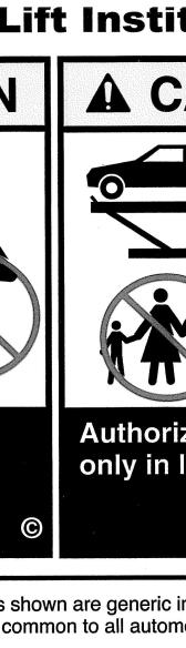
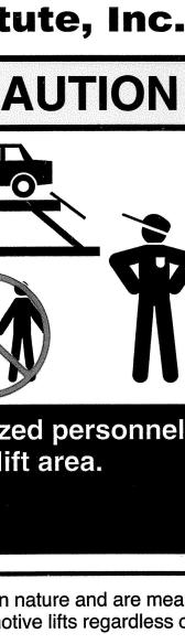


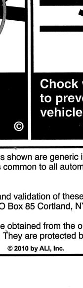

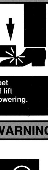
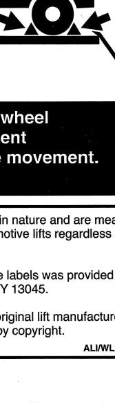
4 1.2 SAFETY WARNING LABELS FOR 4-POST SURFACE MOUNTED ROLL-ON LIFTS SAVE THESE INSTRUCTIONS 4
5 2. TABLE OF CONTENTS 1. OWNER / EMPLOYER OBLIGATIONS IMPORTANT SAFETY INSTRUCTIONS SAFETY WARNING LABELS FOR 4-POST SURFACE MOUNTED ROLL-ON LIFTS TABLE OF CONTENTS GENERAL SPECIFICATIONS TOOLS REQUIRED FOR INSTALLATION PACKAGING CONTENTS INSTALLATION INSTRUCTIONS CHALK LINE LAYOUT IDENTIFICATION OF MAIN LIFT COMPONENTS FRONT CROSS-MEMBERS AND TOWER ASSEMBLIES ANCHOR FRONT TOWERS DECK ASSEMBLIES (FRONT) REAR CROSS-MEMBER AND TOWER ASSEMBLIES DECK ASSEMBLIES (REAR) CABLE INSTALLATION SAFETY RELEASE AIR LINES INSTALL SHEAVES. FINALIZE CABLE INSTALLATION POWER PACK AND HYDRAULIC HOSE INSTALLATION MOUNTING LIGHTS & LOCKS CONTROL BOX (OPTIONAL) JACKING BEAM AIR LINE FRONT AND REAR LIGHT KIT CONNECTIONS (OPTIONAL) FINALIZE AIR LINE INSTALLATION FINALIZE LIGHTS & LOCKS INSTALLATION (OPTIONAL) LOCKING FRONT TURNPLATES & REAR SLIP PLATES (OPTIONAL) FILTER/REGULATOR/LUBRICATOR COMMISSIONING (OPTIONAL) ELECTRICAL CONNECTIONS LIGHTS & LOCKS CONTROL BOX (OPTIONAL) LIGHTS & LOCKS CONTROLS (OPTIONAL) DECK LEVELING PROCEDURE ANCHOR REAR TOWERS APPROACH RAMPS, WHEEL STOPS, PULLEY COVERS OPERATING INSTRUCTIONS RECOMMENDED INSPECTION AND MAINTENANCE LUBRICATION SPECS WIRE ROPES FASTENERS SHEAVES AND PINS MECHANICAL SAFETY LATCHES (DOGS) CABLE BREAK SAFETY MECHANISM AIR CYLINDERS, AIR LINES, VALVE AND FITTINGS HYDRAULIC POWER PACK AND HOSE HYDRAULIC CYLINDER RUNWAYS COLUMNS APPROACH RAMPS, CHOCKS, FRONT WHEEL STOPS FRONT AND REAR STEER PLATES ROLLING AIR JACKS ENTIRE LIFT LIFT LOCKOUT / TAGOUT PROCEDURE
6 9.1 PURPOSE RESPONSIBILITY PREPARATION SEQUENCE OF LOCKOUT PROCEDURE RESTORING EQUIPMENT TO SERVICE RULES FOR USING THE LOCKOUT PROCEDURE PARTS LIST PARTS LIST - LIFT ASSEMBLY PARTS LIST FRONT TOWER ASSEMBLY, POWER PARTS LIST REAR CROSS-MEMBER EXPLODED VIEW - LOCKS & LIGHTS (OPTIONAL) PARTS LIST FRONT CROSS-MEMBER, LS PARTS LIST FRONT CROSS-MEMBER, RS PARTS LIST - DECK ASSEMBLY, LEFT SIDE EXPLODED VIEW - LOCKS & LIGHTS (OPTIONAL) PARTS LIST - DECK ASSEMBLY, RIGHT SIDE EXPLODED VIEW - LOCKS & LIGHTS (OPTIONAL) PARTS LIST CYLINDER ASSEMBLY P/N: ARTS LIST - CABLE ROUTING PARTS LIST - AIR AND HYDRAULICS FILTER/REGULATOR/LUBRICATOR ASSEMBLY PARTS LIST - POWER PACK EXPLODED VIEW - LOCKS & LIGHTS (OPTIONAL) EXPLODED VIEW - LOCKS & LIGHTS (OPTIONAL) MAINTENANCE RECORD
7 3. GENERAL SPECIFICATIONS Maximumm Capacity Maximumm Wheelbase General Service Maximumm Wheelbase 2-Wheel Alignment Maximumm Wheelbase 4-Wheel Alignment Minimumm Wheelbasee 4-Wheel Alignment Overall Length Overall Width Lowered Runway Height Maximumm Lifting Height (to runway surface) 14,000 lb /8 140 ½ kg 5207 mm 4775 mm 4013 mm 1778 mm 6874 mm 3569 mm 178 mm 1879 mm Rise Time Ramp approach angle (no shims) 70 Seconds 10 Power Requirements Standard motor 230VAC, 1PH., 20A, 60 Hz Optional motor /460VAC, 3PH., 9A, 60 Hz Shipping Weight Maximumm Operating Pressure (Full Load): 4206lb 3180 psi 1908 kg 219 bar NOTE: Dimensions in Figure 1 and Figure 2 are reference dimensions, It is critical to ensure that front cross- as members are positioned during installation defined in Figure 14 at page 17. Figure 1 7
8 4. TOOLS REQUIRED FOR INSTALLATION ROTARY HAMMER DRILL 3/4 CONCRETE DRILL BIT 1/2 CONCRETE DRILL BIT 4 LEVEL HAMMER (for anchor installation) PRY BAR (for shim installation) CHALK LINE (lift location) TAPE MEASURE ELECTRICAL TAPE STEP LADDER (adjusting cables and/or safety ladder in posts) SIDE CUTTERS (for cutting shipping straps) 4 WORK STANDS (set up) STANDARD SOCKETS AND WRENCHES ALLEN KEY SET SCREWDRIVER SET FLOOR JACK OR ENGINE HOIST BOX CUTTER / SNIPS (to remove packaging) RUBBER OR PLASTIC MALLET 5. PACKAGING CONTENTS The lift is packaged to protect it from damage during shipping. The two deck assemblies and crossmembers are packaged together with the accessory boxes strapped to them. Main Structural Components: 1 - Left Side Deck Assembly (complete with hydraulic cylinder) 1 - Right Side Deck Assembly 1 - Front LS Cross-member Assembly (with air cylinder release locks) 1 - Front RS Cross-member Assembly (with air cylinder release locks) 1 - Rear Cross-member Assembly (with air cylinder release locks) Accessory Box Contents: Table 1:Accessory Box Contents Hardware Kit (with separate packaging list) 1 Top plate, Front Towers 2 Top plate, Rear Towers 2 Cross-Member Sheave Pins 4 Deck Sheave Pin 5 Sheave Weldment/Assembly 11 Spacer, Sheave, 1-11/16 Lg. 2 8
9 Spacer, Sheave, 3-3/16 1 Spacer, Sheave, 1/4" Lg. 1 Spacer, Sheave, 1 Lg. 3 Spacer, Sheave, 2-1/4 Lg. 2 Spacer, Sheave, 7/8 Lg. 8 Glide Block Spacer 4 Front Sheave Cover 2 Rear Sheave Cover 2 Plastic Glide Block, Swivel (rear cross-member) 4 Plastic Insert 4 Shim, 20GA, for Slider Blocks 8 Glide (Slider Block, front cross-member) 8 Front Left Cable, 391 Lg. 1 Rear Left Cable, 155-1/2 Lg. 1 Rear Right Cable, 217-1/2 Lg. 1 Front Right Cable, 433 Lg. 1 Hose Guard 1 Air valve and Air Filter Assembly 1 Hydraulic Hose Assembly (16ft. lg.) 1 Power Unit 1 Duty Cycle Decal 1 Headed pin (approach ramp, wheel stop) 8 Wheel Stop Weldment 2 Approach Ramp Assembly 2 Rubber Wheel Chock 2 Polytube, 1/4" OD, Black 45ft Polytube, 3/8 OD, Black 16.67ft Installation & Operation Manual 1 Lift it Right Manual ALI 1 Lift it Right Safety Tips 1 ALI Standards 1 ALI Quick Reference Guide 1 9
10 6. INSTALLATION INSTRUCTIONS PLEASE TAKE THE TIME TO READ THESE INSTRUCTIONS COMPLETELY. A QUICK CHECK OF THE CONTENTS OF THE ACCESSORY BOX WOULD ALSO DECREASE THE INSTALLATION TIME. Gather the tools and materials required for the installation. Select the location best suited for your lift. NOTE: In determining lift area check for the following: - Ease of driving a vehicle on and off the lift. - Overhead obstructions, low ceiling height, overhead doors, overhead heaters etc. Minimum ceiling clearance must be 12 ft. Lower ceiling heights may interfere with servicing some vehicles - Floor obstructions, drains, uneven floor in lift area, work benches, electrical wiring in floor, etc. ATTENTION! This lift is intended for indoor installation only. It is prohibited to install this product outdoors. Operating environment temperature range should be F (5 40 C). Failure to adhere will result in decertification, loss of warranty, and possible damage to the equipment. IMPORTANT: It is the user s responsibility to provide a satisfactory installation area for the lift. Lifts should only be installed on level concrete floors with a minimum thickness of six (6) inches or 150mm. Concrete must have a minimum compressive strength of 3000 psi (21 MPa) and should be aged thirty (30) days prior to installation. Please consult the architect, contractor or engineer if doubt exists as to the strength and feasibility of the floor to enable proper lift installation and operation. It is the user s responsibility to provide all wiring for electrical hook-up prior to installation and to insure that the electrical installation conforms to local building codes. Where required, it is the user s responsibility to provide an electrical isolation switch located in close proximity to the lift that will enable emergency stop capability and isolate electrical power from the lift for any servicing requirements. Recommended clearance around the lift is 3 to 4 feet. Ensure clearance conforms to local building and fire codes. Recommended overhead clearance is a minimum twelve (12) foot ceiling providing 6 feet for the maximum lift height and 6 feet for the supported vehicle. For vehicles taller than 6 feet it is recommended that the user provides additional overhead clearance or a shut off mechanism to stop the lift from raising the vehicle too high. An outline matching the dimensions shown in Figure 2 will need to be marked on the floor. Refer to Figure 2 for outline dimensions. Refer to General Lift Specifications for overall lift dimensions. DO NOT install the lift on asphalt or other unstable surface. Lift columns are supported only by anchors in floor. INSTALLER: PLEASE RETURN THIS BOOKLET TO LIFT OWNER/OPERATOR AFTER COMPLETING INSTALLATION 10
11 6.1 CHALK LINE LAYOUT Figure 2 None of the front anchors shall be closer than 4-3/4" to any edge of a concrete slab, expansion joint or crack in the garage floor. Review position of front towers, base plates and anchors, and relocate lines "A", "B", "C" if needed. Refer to Figure 2. Make a chalk line parallel to the doorway at least 288-5/8 from the doorway. This will be the location for the front edges of the front tower base plates. Call this line "A". Determine the center of the doorway and bay. Make a centerline to intersect with line "A". Make two chalk lines spaced 54-3/4 to the left and right side of the centerline (109-1/2 apart). Call these lines B and C respectively. These will be the locations of the inside edges of the front tower base plates. Make a chalk line spaced 237-1/2 to the back from line A. Call this line D. This is the position of the rear edges of the rear tower base plates. Make two chalk lines spaced 55-9/32 to the left and right side of the centerline (110-9/16 apart). Call these lines E and F respectively. These will be the locations of the inside edges of the rear tower base plates. 6.2 IDENTIFICATION OF MAIN LIFT COMPONENTS Identify and unpack major lift components (cables, columns, traverse beams) and place them where they belong (front left, front right etc.) See Fig.3. 11


12 Place components in their approximate locations. Do not unwind cables at this point. Leave cables coiled, close to their respective towers. Place runways (decks) about 40 apart and about 3 ft behind line A Figure 3 12

 into front left cross-member, non-stud end first, as shown in Fig.4 and Fig.")
13 Identify and place coiled cables as follows, close to their respective towers (Table 2): CABLE P/N LOCATION LENGTH FRONT LEFT 398-1/ REAR LEFT 165-1/2" REAR RIGHT 224-3/ FRONT RIGHT 450-1/4 Table 2: Cable part numbers 6.3 FRONT CROSS-MEMBERS AND TOWER ASSEMBLIES Lay front left tower on its back, with base plate close to its final position (see chalk lines) and top pointing to the rear of the lift and slightly to the left. Position left front cross-member to the end of front left tower, as shown in Figure 4. Insert safety plate (ladder) into front left cross-member, non-stud end first, as shown in Fig.4 and Fig.5 Insert safety ladder until main safety latch (dog) engages into 2 nd safety cutout. See Fig. 5 NOTE: When installing the Safety Ladders, ensure they pass in-between the guide rollers as shown. Figure 4 Figure 5 13
 in accessory box.")
 NOTE: Spacer is intended to allow the safety ladder to float, after assembled the top plate, ensure the ladder is")
14 Assemble slider blocks to front cross-member (See Figure 6) Figure 6 Slide front cross-member (with safety ladder mounted) into front tower, until safety ladder has touched the tower base plate. Retrieve front tower top plate (Figure 7) in accessory box. Retrieve 2 flat washers (1/2 ID), 2 lock washers (1/2 ID), 2 HHCS (1/2 UNC x 1-3/4 LG), 2 SAE flat washers (3/4 ID), 4 hex nuts (5/8 UNC) and 1 spacer from the hardware kit. Assemble top plate to front tower and safety ladder to top plate as shown (Figure 8) NOTE: Spacer is intended to allow the safety ladder to float, after assembled the top plate, ensure the ladder is free to move in the slot. Figure 8 Figure 7 Stand up tower, move into position at the front of the lift (see Fig.10), and line up with lines A and B. Handle tower and front cross-member only by the tower. As the cross-member is only restrained to the tower by safety locks, care must be taken when handling tower with crossmember. None of the front anchor holes shall be closer than 4-3/4" to any edge of a concrete slab, expansion joint or crack in the garage floor. If this situation occurs, relocate chalk layout before continuing installation 14

 as shown in Figure 10 and Figure 11.")

15 Support front cross-member with a jack stand as shown (Fig.10). Stand should be placed close to tower. Repeat above steps for front right tower and right front cross-member. Align to lines A and C (See Figure 9) Figure 9 Use a 4 level, to level the posts vertically (shim if necessary) as shown in Figure 10 and Figure 11. Figure 10 Figure 11 IF THE TOWERS ARE LEANING INTO THE LIFT, THE CROSS MEMBERS CAN BECOME WEDGED INTO THE TOWERS AS THE LIFT RAISES. Level columns so that they are plumb to each other, making sure the distance between deck contact surfaces of the runway stoppers (surfaces A and B ) is 40 (Fig.12). 15


16 Figure 12 Use a straight edge (string line) along front side of beams along with 1/8 column shim provided and ensure equal spacing throughout entire area of both beams (Fig.13). Rotate the columns if required to make cross-members parallel. Figure 13 16

. In case longer anchors are required, supplied anchors can be hammered through concrete.")

17 6.4 ANCHOR FRONT TOWERS Prior to installing anchors, assemble the nut and washer onto anchors. A minimum of six threads must be visible below the surface of the nut. Refer to the Figure 14 while reading through the following instructions. Figure 14 If shop floor is not level, determine which front tower sits on higher floor Using a 3/4 concrete drill bit and rotary hammer drill, drill 3/4 holes for the anchor bolts on the high side column. Drill completely through the concrete floor (Fig.15). In case longer anchors are required, supplied anchors can be hammered through concrete. Figure 15 Clean out the drilling dust from the holes and hammer in the anchor bolts until they make contact with the base plate. Hand-tighten all anchor bolts. Check that the column is level front to rear and side to side. Adjust shims as required. If excessive shimming (greater than 5/16 ) is required, grout or additional support is required under the towers. Torque all anchor bolts to 110 ft-lbs. (150 Nm), continually checking that the column is level as you proceed. Figure 16 NOTE: The 3/4 7 lg. wedge anchor bolts supplied must have a minimum embedment of 4 into the concrete floor. 17
 of shims.")
18 NOTE: If anchors do not tighten to required torque, OR project more than 3 above the concrete surface, the concrete under the towers may not be sufficient and need to be replaced by an appropriate concrete pad. NOTE: In cases where the floor is extremely out of level, the mechanical safety latches may not engage on the same lock DO NOT use more than 1/2 (13mm) of shims. Anchor bolts supplied allow for a maximum of 1/2 (13mm) of shim. If more than 1/2 (13mm) of shims are required, DO NOT proceed with installation and contact Snap-on Equipment Technical Support for further details. NOTE: Refer to Fig.1 and Fig.2 to ensure that the column is still in the proper position. Repeat procedure for the other front tower. 6.5 DECK ASSEMBLIES (FRONT) Raise left side deck and place the front end plate of deck on top of front cross-member. Ensure the mounting slots in deck end plate line up with (threaded) mounting holes in cross-member. Support rear end on a jack stands (Fig.17). Figure 17 Insert 1/2-13 HHCS x 1-1/2 long bolts, 1/2" washers and 1/2" lock washers thru slots in the front end plates, into cross-member tube (see Fig.18). Do not tighten bolts. This will be completed in 6.7. Figure 18 18
.")


 into rear cross-member, non-stud end")
19 Insert 1/2" UNC hex bolt in the jacking plates on cross-memberss (Fig. 19). The 1/2" UNC hex bolts are found in the hardware kit. Do not tighten the bolt at this time. Repeat proceduree for the right side deck. Figure REAR CROSS-MEMBER AND TOWER ASSEMBLIES Remove rear cross-member from packaging and place it with cut-outs pointing up and the ends close to the rear towers tops, lying on the floor. Depending on the space available on the shop floor, rear towers and cross-members will be laid out in one of the 2 following situations: Figure 20 Figure 21 Insert safety plates (ladders) into rear cross-member, non-stud end first, as shown in Fig..22. Insert safety ladder until main safety latch (dog) engages into 4 th safety cutout. See Fig.22. Figure 22 19

.")
 into rear towers,")
20 Assemble sliders into the rear cross-member (Fig.23). NOTE: Bevelled edges to be placed away from the traverse beam. Figure 23 Depending on the layout chosen for rear towers and cross-member, insert the cross-member in one of two ways: - Keep towers fixed on the floor and push rear cross-member toward the lift (Fig.24). - Push towers toward the back and gradually lift cross-member (Fig.25). Figure 24 Figure 25 Figure 24 Slide rear cross-member (with safety ladders mounted in) into rear towers, until safety ladder touches the base plate (Fig.26). Note orientation of slider blocks inside the rear tower (Fig.26). Figure 26 20
, 2 lock washers (1/2 ID), 2 HHCS (1/2 UNC x 1-3/4 LG), 1 SAE flat washers (5/8 ID), 4 hex nuts (5/8 UNC), 1 Ø11/16 x Ø2 x 1/4 THK washer and 1 Ø5/8 x Ø3/4 x 19/32 LG")

21 Retrieve rear tower top plate in accessory box. Retrieve 2 flat washers (1/2 ID), 2 lock washers (1/2 ID), 2 HHCS (1/2 UNC x 1-3/4 LG), 1 SAE flat washers (5/8 ID), 4 hex nuts (5/8 UNC), 1 Ø11/16 x Ø2 x 1/4 THK washer and 1 Ø5/8 x Ø3/4 x 19/32 LG spacer from the hardware kit. Assemble top plate to rear tower and safety ladder to top plate as shown (Fig.27) Repeat operation for second rear tower. NOTE: Spacer is intended to allow the safety ladder to float, after assembled the top plate, ensure the ladder is free to move in the slot. Note: Front tower shown in illustration as assembly is the same. Figure 27 Stand up towers, move into position at the back of the lift (see Fig.2 and Fig.28), and line up with lines E, F and D. As the cross-member is only restrained to the tower by safety locks, care must be taken when handling towers with cross-member. Support rear cross-member with a jack stand as shown (Fig.28). Stand should be placed close to tower. If sub-assembly consisting of rear towers and rear cross-members is unstable, provide additional support for both towers 6.7 DECK ASSEMBLIES (REAR) Adjust height of decks or rear cross-member until end plates of decks rest on top of rear crossmember and the mounting slots in deck end plates line up with (threaded) mounting holes in rear cross-member. The rear cross-member should butt up against the deck. Insert 1/2-13 HHCS x 1-1/2 long bolts, 1/2" washers and 1/2" lock washers thru slots in the front end plates, into cross-member tube (see Fig.28). Do not tighten bolts. 21

 till the deck is flush against the stop on the opposite side.")
.")
22 Figure 29 Figure 28 Insert 1/2" UNC hex bolt in the jacking plates on cross-members (Fig.29). The 1/2" UNC hex bolts are found in the hardware kit. Back off the 4 bolts on the front and rear jacking plates, one at a time, Apply Loctite on the bolt threads, then tighten (Fig.19, Fig.29) till the deck is flush against the stop on the opposite side. Do not over-tighten. Check all lift dimensions, and make adjustments if necessary. Tighten bolts mounting the decks to front and rear cross-members (see Fig.18 and Fig.28). Transfer jack stands from under the decks to under rear cross-member (Fig.30). Figure 30 22
![6.8 CABLE INSTALLATION REFER TO [Fig.46-a] FOR GENERAL CABLE ROUTING DIAGRAM. 6.8.1 Routing Front Left Cable Anchor threaded end of the front left cable into the top plate of the front left tower (Fig.](/docs-images/72/67867393/images/23-0.jpg "31). Use one 7/8 ID flat washer and two 7/8-14 UNF hex nuts (see hardware kit).")
. Pull sleeve end of the cable through the crossmember opening under the front of the left side runway (Fig.")

23 6.8 CABLE INSTALLATION REFER TO [Fig.46-a] FOR GENERAL CABLE ROUTING DIAGRAM Routing Front Left Cable Anchor threaded end of the front left cable into the top plate of the front left tower (Fig.31). Use one 7/8 ID flat washer and two 7/8-14 UNF hex nuts (see hardware kit). Figure 31 Continue routing the cable, non-threaded sleeve first, through the slot in the top stiffener plate, through the front left cross-member (Fig.32). Pull sleeve end of the cable through the crossmember opening under the front of the left side runway (Fig.33) NOTE: It is very important to route the cable inside a cross-member IN FRONT of the cable retainer shaft (see detail in Fig.32). Routing the cable behind the cable retainer shaft will not allow the cable to sit in the pulley groove and will cause damage to the lift. Figure 32 Figure 33 23
. Figure 34 Continue routing the cable, non-threaded sleeve first, through the rear cross-member.")
.")
24 6.8.2 Routing Rear Left Cable Anchor threaded end of the rear left cable into the top plate of the rear left tower (Fig.34). Use one 7/8 ID flat washer and two 7/8-14 UNF hex nuts (see hardware kit). Figure 34 Continue routing the cable, non-threaded sleeve first, through the rear cross-member. Pull sleeve end of the cable through the smaller opening under the rear of the left side runway (Fig.35). NOTE: It is very important to route the cable inside a cross-member IN FRONT of the cable retainer shaft (see detail in Fig.32). Routing the cable behind the cable retainer shaft will not allow the cable to sit in the pulley groove and will cause damage to the lift. Figure 35 24
, through the front right cross-member.")
25 6.8.3 Routing Front Right Cable Anchor threaded end of the front right cable into the top plate of the front right tower. Use one 7/8 ID flat washer and two 7/8-14 UNF hex nuts (see hardware kit). Refer to Fig.31. Continue routing the cable, non-threaded sleeve first, through the slot in the top stiffener plate (Ref. Fig.32), through the front right cross-member. Pull sleeve end of the cable through the cross-member opening under the front of the right side runway (Fig.36). Figure 36 Continue routing the cable toward the rear of the right side runway (deck) Routing Rear Right Cable Anchor threaded end of the rear right cable into the top plate of the rear right tower. Use one 7/8 ID flat washer and two 7/8-14 UNF hex nuts (see hardware kit). Refer to Fig.35. NOTE: It is very important to route the cable inside a cross-member IN FRONT of the cable retainer shaft (see detail in Fig.32). Routing the cable behind the cable retainer shaft will not allow the cable to sit in the pulley groove and will cause important damage to the lift. Continue routing the cable, non-threaded sleeve first, through the rear cross-member, up to the right side opening. NOTE: Do not twist cables inside the tubes. On the right side, at the rear right opening (Fig.37), take the non-threaded plugs of the rear right cable and front right cable and tape them together with the RS rear cable on top, and feed both cables thru the window of the traverse beam. 25


26 Figure 37 Pull both cables out through the LARGE opening on the left side of the rear cross-member (Fig.38). Figure SAFETY RELEASE AIR LINES Install RS airline from the Tee fitting in front traverse beam to the fitting in rear traverse beam and zip tie in locations A, B, C,..., H identified below (Fig.39). Figure 39 Route LS air line from the tie "A" thru the TUBE and connect to the TEE fitting on the left side of rear cross-member. if necessary, reach with the hand thru window "W" in rear cross-member to hold TEE fitting while inserting air line. 26
.")


27 Figure 40 Continue routing LS airline towards the front of the deck and zip tie in locations B, C,D and E. (Fig.40). At this point, leave the excess air line aside, and continue with installation. Do not install air line onto F, G, H, as this will be done after all the lines and hydraulic hose are installed, in INSTALL SHEAVES. FINALIZE CABLE INSTALLATION Retrieve the deck sheaves, deck sheave pins (Ø1-1/2 x 6 3/8 long), and deck sheave spacers from the accessory box. Retrieve the nylon thrust washers from the hardware kit. Pleasee see following table for sheave spacer dimensions and location. See Fig. 41 for position of sheave spacers. Note: Failure to install spacers and Nylon washers will result in premature cable or sheave failure and void warranty. Table 3: Spacers size and location L.S. DECK, REAR 27 Figure 41


.")
.")


28 Check that the cables are routed as in Fig. 42-a and Fig. 42-b. Figure 42-b Rear Pulleys Detail Figure 42-c Cables into Cable Flange Figure 42-a Cable Routing Remove the two hex head bolts retaining the anti-rotation bar to the cable flange at the threaded end of the hydraulic cylinder (Fig.43). Carefully slide the anti-rotation bar towards the cylinder (Fig.44). Figure 44 Figure 43 NOTE: THE CYLINDER ROD MUST BE FULLY EXTENDED IN ORDER TO ATTACH THE NON-THREADED ENDS (SLEEVES) OF THE CABLES TO THE CABLE FLANGE ON CYLINDER ROD. USE COMPRESSED AIR IN THE SHOP AND AN AIR NOZZLE AT THE BREATHER END TO EXTEND THE CYLINDER ROD. USE CAUTION AND PROTECTIVE EQUIPMENT WHEN WORKING WITH COMPRESSED AIR. 28


. Figure 46.a, b.")
29 Insert unthreadedd studs of the cables into the cable flange as shown in Fig. 45. Figure 45 Unthreaded stud end of the cables must be installed to the cable flange in the positions noted in Figure 42.c. Ensure that the unthreaded stud ends are properly seated in the counter bores of the cable flange. Note the orientation of the anti-rotation bar with respect to cable flange and cylinder rod (Fig. 46.a, Fig. 46.b). Figure 46.a, b. Seating the cable in the cable flange slots Once all cable have been routed, re-install the cable retainer and the 2 hex head bolts. 29

30 6.11 POWER PACK AND HYDRAULIC HOSE INSTALLATION NOTE: WHEN WORKING WITH HYDRAULIC LINES AND VALVES, IT IS IMPORTANT TO KEEP ALL COMPONENTS CLEAN AND FREE OF DIRT. POWER PACK DETAILS Figure 47 Figure 48 Install the power pack to the mounting bracket on the front face of the left front post using the 5/16"-18UNC 1"LG. hex head bolts and 5/16" washers, lock washers and hex nuts, found in the hardware kit (Fig.48). Note: Leave the (2) bolts towards the outer of the lift loose in order to install the Filter/Regulator/Lubricator assembly, see Section Fill the reservoir on the power unit with 14 Liters of ISO 32 (10 Hydraulic Weight) hydraulic fluid. Retrieve the hose guard in the accessory box, and install in the opening on the left front side of the left side deck. Retrieve the hydraulic hose from the accessory box. Insert any end of the hydraulic hose through the hose guard, into the front end of the left side deck. Fasten one end to the hydraulic power pack and the other end to the flow control on the hydraulic cylinder. Do not over-tighten hydraulic fittings 30

. 3.")

31 6.12 MOUNTING LIGHTS & LOCKS CONTROL BOX (OPTIONAL) 1. Place the control box between the powerpack and mounting bracket. Use the 5/16" hardware found in the hardware kit to fasten items together. Figure On the inside of the front DS tower, mount the Roller Lever Light Sensor using the #8-32 screws #6-4135, internal lock washers # and flat washers # Ensure the lever is as shown in the below figure with roller towards tower (Fig. 50a). 3. Adjust the Roller Lever arm by loosening the center screw and rotating it downwards until you hear a clicking sound. Slide the arm towards the crossmember until the roller makes contact with the side of the front crossmember. Tighten screw. 4. Use (2) hose clamps # and (2) screws # to secure the sensor cable to the tower. (Fig. 50b). Figure 50a & 50b 5. Follow the electrical schematic to connect the control box to the powerpack. 31


 3/8")


32 6.13 JACKING BEAM AIR LINE Install 3/4" terminal bolt and 1/4" NPTF Tee fitting on the outside of the deck, into the terminal bolt, as shown in Fig.51. At the end of installation, ensure that the branches of the Tee are approximately horizontal Figure 51 Install the 90 elbow 1/4" NPTM to 3/8 tube push-in on the inside of the deck, into the terminal bolt, as shown in Fig.52. Figure 52 Retrieve the (2000 in long) 3/8 in dia. air line from the accessory box. Connect 3/8 tube to the push-in elbow, as shown in Fig.53. Run 3/8 dia. air line over the hydraulic cylinder, along left lip of the deck, and thru the hose guard (Fig.54). Figure 54 Figure 53 32


: Connect the two red connectors for the light system.")
33 6.14 FRONT AND REAR LIGHT KIT CONNECTIONS (OPTIONAL) 1. Starting from the rear underside of the driver side deck assembly: Connect the two red connectors that will send power to the lights on the right side deck assembly (Fig. 55). From the rear crossmember, route the red and blue polytubes through the mounted zip tie on the deck, and then connect to the colour appropriate tee fitting. Tighten the tie wrap and cut excess (Fig. 56).. Figure 55 Figure Next, continue onto the rear of the passenger side deck assembly (Fig. 57): Connect the two red connectors for the light system. From the rear crossmember, route the red and blue polytubes through the tube clamp on the deck, and connect to the colour appropriate tee fitting. Figure 57 Use a zip tie wrap to bundle all lines from the rear crossmember together. 33
 to the front TEE fitting. Connect remaining 1/4 dia. air line to the front TEE fitting and pass free end thru the hose guard, out of the deck. 2.")
 to the mounting bracket on the power post. 4.")
34 6.15 FINALIZE AIR LINE INSTALLATION NOTE: Please refer to the air and hydraulics parts list, page 70, Fig Continue LS safety release air line installation from point E (chapter 6.9, Fig. 40) to the front TEE fitting. Connect remaining 1/4 dia. air line to the front TEE fitting and pass free end thru the hose guard, out of the deck. 2. Zip tie hydraulic hose, jack beam air line and safety release air line together at the locations F, G and H (see Fig.40). 3. Install the air valve and filter assembly (found in the accessory box) to the mounting bracket on the power post. 4. To do this, slide the FRL assembly between the tower bracket and the 5/16" lockwasher. 5. Tighten up the hardware. 6. Connect the 1/4" polytube for the safety system and the 3/8" polytube for the jacking beams. NOTE: When cutting polytube, be sure to cut the line at 90 degrees. Failure to do so may result in leaks in the air connections. NOTE: FOR THOSE UNITS EQUIPPED WITH JACKING BEAMS, THIS IS THE APPROPRIATE TIME TO INSTALL THEM. CONSULT THE JACKING BEAM INSTRUCTION MANUALS FOUND IN EACH JACKING BEAM BOX. 7. Connect the air supply to the inlet on the FRL. Figure 58: FRL Assembly 34
 pneumatic, hydraulic and electrical lines that will be required to connect to the control box: 1.")


35 6.16 FINALIZE LIGHTS & LOCKS INSTALLATION (OPTIONAL) 1. From the front of the DS deck, there will be a total of (7) pneumatic, hydraulic and electrical lines that will be required to connect to the control box: 1. RED Electrical Cable for RS Lights 2. BLUE Electrical Cable for LS Lights 3. RED 1/4" polytube for locking plates 4. BLUE 1/4" polytube for locking plates 5. BLACK 1/4" polytube for safety locks 6. BLACK 3/8" polytube for JackBeams 7. Hydraulic Hose Assembly to cylinder 2. From the access hole in the DS deck, route these lines through the corrugated hose protector. Insert approximate 1"-2" of the hose protector into the access hole on the deck. 3. Locate Hose Guard Clamp # and slide it onto the hose guard between two of its ribs on the outside of the deck. Align the holes to the mounting holes on the deck and faster with 1/4" screws #6-3036, lock washer # and nuts # Figure At the control box, connect the pneumatic and electrical lines as shown in the below figure. Connect the hydraulic hose assembly to the powerpack. 35


36 Figure Locate Hose Guard Clamp # and slide it onto the hose guard between two of its ribs approximately 1"-2" from the end. Align the holes to the mounting holes on the tower and fasten with 1/4" screws # and lock washer # Figure Connect the main air supply to the Filter/Regulator/Lubricator mounted to the outside of the control box (Fitting not included). NOTE: Please refer to the Filter/Regulator/Lubricator commissioning procedure prior to operating lift, page Route the hydraulic line between the tower and tank of the powerpack and connect it to the 90deg fitting on the pump. 36


 are not hitting")

37 6.17 LOCKING FRONT TURNPLATES & REAR SLIP PLATES (OPTIONAL) Installation of Front Turnplates Avoid inserting fingers in the front alignment pan cut-out, if position of the turnplate assembly exposes such openings. Ensure that air supply to the lift is turned off and no person is operating on the console during maintenance of clamping elements of the locking system. During normal use, the front turnplates and rear slip plates may move rapidly, when locking system is activated. This creates pinch points for your fingers or hands. Keep hands clear of these pinch points when lift air supply is connected. No person shall operate console while maintenance or inspectionn of the slip plates is in process. *Note: Objects in pictures may not be exactly as shown. Figure 63a & 63b 1. Lower lift to a comfort height. 2. Place each front turnplate assembly, one by one, on the front alignment pan on runway. Moving handles of the turnplates should be oriented to the outside of lift, shown below. Ensure that the locking system components on the bottom of the turnplate (air cylinder, fittings, and plastic clamping parts) are not hitting against the runway during placement. 3. Verify that the turnplate assembly is completely seated in the front alignment pan. Gently slide each turnplate in the alignment pan, left and right, to verify that they can be positioned for different car widths. Do not hit plastic locking ring forcefully against the edges of the cut-out in the front alignment pan. 4. Connect free ends of front air lines to the turnplate locking cylinder: blue air line to the cylinder port marked with a blue dot and red air line to the cylinder port marked with a red dot [Figure shown below]. 37
 WARNING: Replenish the lubricant after releasing the inlet pressure.")


38 5. Plug the electrical connector on the turnplate light cord into the electrical connector on the cable at the front. Figure 64a & 64b 6.18 FILTER/REGULATOR/LUBRICATOR COMMISSIONING (OPTIONAL) WARNING: Replenish the lubricant after releasing the inlet pressure. Lubrication cannot take place under a pressurized condition 1. Unscrew the lubricator bowl turning it in a counterclockwise direction. 2. Fill the lubricator bowl using Snap-On Air Motor Oil #IM-6 or equivalent. Oil supply to the lubricator should be less than the upper limit of the oil level. The air regulator should be set between P psi. IMPORTANT: Oil other than above may cause damage and dripping failure 3. Screw in the lubricator bowl again 4. Slowly pressurize the system and check for leaks. Note #1: The regulator has been pre-set to operate at 90 psi Note #2: The sight dome assembly has been pre-set to provide 3-5 drips per minute. Check the sight dome assembly and verify that oil drips. 38
39 6.19 ELECTRICAL CONNECTIONS A QUALIFIED ELECTRICIAN SHOULD MAKE ALL ELECTRICAL CONNECTIONS. Refer to Figure 65 for electrical connections. Electrical Breaker must be sized by a qualified electrician. Refer to page 7 for electric motor ratings. Figure 65 Electrical Diagram 6.20 LIGHTS & LOCKS CONTROL BOX (OPTIONAL) Refer to Fig. 66 for electrical schematic on control box. An electrician is to connect the control box leads (wht/grn/blk) into the box on the power pack. Figur66 Electrical Diagram (OPTIONAL) 39

40 6.21 LIGHTS & LOCKS CONTROLS (OPTIONAL) Figure The Light System 1. The light system will illuminate after approximately 24" of travel from the ground and will turn off at the same height, please verify. 2. If you desire to have the light system off at any height above the 24", you can do so by turning the switch on the control box to the "off" position, please verify. 3. If not, check that all connections are correct and there is current to the control box Locking Plate System 4. On the control box, switch the Locking Plate lever to "OFF" to unlock. All locking plates should be free to move, please verify. 5. Now switch the lever to "ON" to lock. All locking plates should be centered and locked, please verify. 6. If not, check that all polytubes connections are correct and there is psi of air pressure. 40
.")

41 6.22 DECK LEVELING PROCEDURE Leveling Lift on the floor Lower the lift completely to the floor. Determine the highest corner of the lift and adjust remaining towers to level the lift, front-to-back and side-to-side (see positions 1, 2, 3, 4 in Fig. 68). Use shims under tower base plate, as needed Leveling Safety Ladders: Raise the lift to a comfortable working height using the hydraulic power pack. Lower the lift onto the nearest safety. Using a 4 level, check the level of the decks front to rear and side to side as shown in Fig.69. Determine the highest corner of the lift. The other 3 corners will need to be raised to the level of the highest corner. This is accomplished by tightening the safety ladder retaining nuts on the top of the tower. Figure 68 NOTE: The lower safety ladder retaining nuts will need to be tightened to jam. It may be easier to remove the cable to gain access to the lower safety ladder retaining nuts. Re-install the cable once the adjustment is complete. Repeat this procedure for all 3 corners while checking the level of the decks. Figure 69 Deck Leveling 41
42 Leveling Lift on Cables: Raise the lift off the safety ladders, at a comfortable working height. Using a 4 level, check the level of the decks front to rear and side to side as shown in Fig.69 Determine the highest corner of the lift. The other 3 corners will need to be raised to the level of the highest corner. This is accomplished by tightening the cable retaining nut on the top of the tower. NOTE: There should be two nuts retaining the cable to the top plate of the tower. The upper nut is used as a jam nut to prevent the lower nut from loosening. Both nuts should be installed after the adjustment is completed. Repeat the preceding steps until the lift is completely level when supported by the cables. Tighten the jam nut after the adjustment is completed. Make sure that the non-threaded sleeve of each wire rope seats in the cable flange properly (See Fig.45.a, Fig.45.b, chapter 6.10). Raise the lift and check that the ladders engage evenly. Lower the lift onto a mechanical safety position. Raise the lift from this position and ensure the lift rises evenly and level from the mechanical locks ANCHOR REAR TOWERS Before proceeding, check that the layout dimensions on Figure 1 and Figure 2 before continuing with anchor installation. Measure diagonally lift dimensions over 2 decks, and distance between decks, and then tighten decks to cross-members. Diagonal distances should be equal within 1/4". At this stage, the rear towers may be slightly off line "D". Check if rear towers are centered with respect to chalk lines E and F, and adjust if necessary. Use a 4 level, to level the posts vertically (shim if necessary) as shown in Figure 70. NOTE: IF THE TOWERS ARE LEANING INTO THE LIFT, THE CROSS-MEMBERS CAN BECOME WEDGED INTO THE TOWERS AS THE LIFT RAISES. Prior to installing anchors, assemble the nut and washer onto anchors. A minimum of six threads must be visible below the surface of the nut. Refer to the Figure 15 for anchoring instructions. If shop floor is not level, determine which rear tower sits on higher floor. Using a 1/2 concrete drill bit and rotary hammer drill, drill 1/2 holes for the anchor bolts on the (high side) column. Drill completely through the concrete floor. (Fig.71). In case longer anchors are required, supplied anchors can be hammered through concrete 42

 is required, grout or additional support is required under the towers. Torque all anchor bolts to 55 ft-lbs.")

 of shims.")
43 Figure 70 Figure 71 Clean out the drilling dust from the holes and hammer Figure 72 in the anchor bolts until they make contact with the base plate. Tighten all anchor bolts (Fig.72). Check that the column is level front to rear and side to side. Adjust shims as required. Ensure that the base plate is completely supported by shims, Including near the center, where it does not contact the floor. If excessive shimming (greater than 5/16 ) is required, grout or additional support is required under the towers. Torque all anchor bolts to 55 ft-lbs. (75 Nm), continually checking that the column is level as you proceed. Do not exceed tightening torque. NOTE: The 1/2 4½ lg. wedge anchor bolts supplied must have a minimum embedment of 2 into the concrete floor. NOTE: If anchors do not tighten to required torque, OR project more than 2-1/2 above the concrete surface due to floor slope, contact a foundation engineer to determine the best course of action. NOTE: In cases where the floor is extremely out of level, the mechanical safety latches may not engage on the same lock DO NOT use more than 1/2 (13mm) of shims. Anchor bolts supplied allow for a maximum of 1/2 (13mm) of shim. If more than 1/2 (13mm) of shims are required, DO NOT proceed with installation and contact Snap-on Equipment Technical Support for further details. NOTE: Refer to Bay Layout to ensure that the column is still in the proper position. Repeat procedure for the other rear tower. NOTE: THE 40 DIMENSION SHOWN IN FIGURE 1 AND FIGURE 2 IS CRITICAL, AS IT IS NECESSARY TO ALLOW THE JACKING BEAMS TO ROLL FREELY. 43

.")
44 6.24 APPROACH RAMPS, WHEEL STOPS, PULLEY COVERS Retrieve the approach ramps, wheel stops and pulley covers from the accessory box. Install short pulley covers to rear cross-members. Install long pulley covers to front cross-members. Install the front wheel stops at the front of the decks, using Ø3/4 x 1-1/2 LG headed pins, Ø3/4 SAE washers and Ø1/8 x 1-1/2 LG cotter pins (Qty.2 per each wheel stop). Figure 73 Headed pins are found in the accessory box. Cotter pins and washers are found in hardware kit. Install the approach ramps at the rear of the decks with Ø3/4 x 1-1/2 LG headed pins, Ø3/4 SAE washers and Ø1/8 x 1-1/2 LG cotter pins (Qty.2 per each approach ramp). Install short pulley covers to both sides of rear cross-member. Figure 74 Ensure the proper operation of the approach ramps. Cycle the lift several times to check proper operation of the cables, safety lock, air locks, etc. with & without load. 44
45 STOP IMMEDIATELY IF THE LIFT IS NOT OPERATING PROPERLY! Make any necessary adjustments and check again for proper operation. NOTE: IF THE LIFT IS EQUIPPED WITH JACKING BEAMS, THIS IS THE APPROPRIATE TIME TO INSTALL THEM. CONSULT THE JACKING BEAM INSTRUCTION MANUALS FOUND IN EACH JACKING BEAM BOX. Before attempting to operate the lift, please ensure that slider guide surfaces inside the front towers are greased adequately. 7. OPERATING INSTRUCTIONS To avoid personal injury and/or property damage, permit only trained personnel to operate the lift. After reviewing these instructions, get familiar with lift controls, by running the lift through a few cycles before loading vehicle on lift. Observe and heed SAFETY and WARNING labels on the lift. LIFT OPERATION - Loading: Lift must be fully lowered, and no one in the service bay while the vehicle is brought in. If the lift is equipped with rolling jacks, jacks must be fully lowered and the rear jack pushed toward center of lift, to provide under-car clearance. - Stop vehicle before it contacts the front wheel stops. At all times, be sure the rear wheels are forward of the approach ramps/chocks and the approach ramps/chocks will clear the tires when the lift is raised. Driver must exit the vehicle before rising. - Place triangular wheel chocks on front and rear of one of the rear tires. - To raise the lift: Push the RAISE button on the power unit. Release button at desired height, ensure that all corners have passed a mechanical lock position. - After raising the lift to the desired height, press and hold the lowering lever on the hydraulic power unit, until lift stops on safety latches. Cross-members should be stopped on safety latches in all 4 towers before any work can start on the raised vehicle. If any of the safety latches is not engaged, try to raise or lower the lift to the next higher or lower safety position, and observe again if all 4 safety latches have engaged. If the problem persists, lower and unload the vehicle, solve the lift safety problem, and only then resume vehicle service. - Before lowering lift: be sure no one is in the lift area and that all tools, tool trays, etc. have been removed from under the lift and vehicle. If the lift is equipped with rolling jacks, jacks must be fully lowered and the rear jack pushed toward center of lift, to provide under-car clearance. 45
46 The runways, approach ramps, and cross-members are designed to rest on the floor when fully lowered. Observe pinch point warning decals. - To lower lift: if lift has been resting on the safety latches, the lift has to be raised high enough for all 4 safety latches to clear the openings in the latch plate (safety ladder). - Actuate the latch release valve on the power unit column to disengage all four locking latches. Hold actuator until lift is fully lowered. NOTE: If actuator on air valve is released, the latches will automatically reset to the engaged position. - Push the lowering handle on the power unit to lower the lift. - Observe lift and vehicle to be sure lift is level while being lowered. If not, STOP the lift and try to resume lowering as explained above. - Fully lower lift, remove the triangular wheel chocks and check to be sure area is clear before removing vehicle from lift. - If lift is not operating properly, do not use until adjustment or repairs have been made by qualified lift service personnel. - For Rolling Jack operating instructions, see Rolling Jack Installation, Operation and maintenance Instructions in the rolling jack shipping box. Do not operate lift with pulley covers removed from cross-member ends. Keep hands clear of the cross-member ends when lift is being raised or lowered. Do not raise or lower the lift while the jack beams are loaded. 8. RECOMMENDED INSPECTION AND MAINTENANCE 8.1 LUBRICATION SPECS Where hydraulic oil is required Where grease is required Where multipurpose lube is required Where pneumatic oil is required Where cable lube is required > ISO 32 10W - non detergent hydraulic oil > multi-purpose lithium grease > multi-purpose SAE 30 lubricating oil > Snap-On air motor oil IM1PT > 2001 MONOLEC wire rope lubricant or equivalent If you are not completely familiar with automotive lift maintenance procedures, STOP. Contact Snap-on Equipment Technical Support for instructions. To avoid personal injury, permit only qualified lift service personnel to perform maintenance on this equipment. Always raise lift when cleaning floor area with solvents and/or cleaning compounds. Always replace cable break safety springs when replacing cables. 46
47 Please refer to the following table for specific inspection and maintenance frequency. COMPONENT Entire Lift and surrounding area 8.15 Entire Lift Operation 8.15 Fasteners 8.3 INSPECTION FREQUENCY DAILY WEEKLY MONTHLY QUARTERLY Wire Ropes Sheaves Sheave Pins SEMI- ANNUALY Safety Dogs Slack Cable Devices 8.6 Latch Plates (Ladders) 8.6 Air Filter, Regulator, Lubricator Air Lubricator Oil Level Approach Ramps, Chocks, Wheel 8.12 Stops Anchor Bolts Turn Tables and Rear Slip Plates Bearing Cage / Rear Slip Plates Edges of Cable Flange Slots Runways ANNUALY As shown before, and ALI Standard Columns Air cylinders, Lines, Fittings 8.7 Hydraulic Power Pack, Hose, Fittings Hydraulic Cylinder 8.9 Jack Beam Rails, Oil Drain Pan Anti-skid Surfaces Rolling Air Jacks


48 8.2 WIRE ROPES Wire ropes are critical to safe and reliable performance of your lift. Cables are expendable items and should be replaced as a set WIRE ROPE CONDITIONS GUIDE Typical good cable Cable with necking Broken wires Excessive wear of wires Rust on sheave stack and ropes Corrugated sheave groove Figure 75 48
49 8.2.2 WIRE ROPE REPLACEMENT CRITERIA: If any cable is found to be in need of replacement, the entire cable set, pulleys and safety rollers must be replaced immediately. See 8.2.1, cable conditions guide. In the following table, "lay" means the distance measured along a line parallel to the axis of the rope in which the strand makes one complete turn about the axis of the rope, or the wires make a complete turn about the axis of the strand. The wire rope must be removed from service if one or more of the following criteria are met: 1. More than six randomly distributed broken wires in one rope lay or 6d length. 2. More than three broken wires in one strand in one rope lay or 6d length. 3. Three or more broken wires at rope terminations. 4. One outer wire broken at the point of contact with the core of the rope which has worked its way out of the rope structure and protrudes or loops out from the rope structure 5. Heavy rusting, corrosion, or pitting. A light surface corrosion on outer wires is normal. 6. Wear or scraping of one-third of the original diameter of outside individual wires 7. Excessive stretch. It is normal for new cable to require adjustment during break-in, after which small periodic adjustments may be required. However, if a cable that has been in service for 6 months should suddenly require frequent adjustments or has used all the cable adjustment available, all cables must be replaced immediately. 8. Deformed strands, kinking, crushing, bird-caging, or any other damage or distortion of wire rope structure 9. Variations in diameter (necking) or any change from normal appearance 10. Reductions from nominal diameter of more than 1/32" (for cables 3/8" to 1/2" dia. inclusive) 11. End attachments cracked, deformed or worn WIRE ROPE INSPECTION Inspect wire rope cables for wear or damage. Wipe cables with a rag to detect hard to see small broken or frayed cable strands. See chapter 8.2, Fig.75 and ANSI/ALI ALOIM standard WIRE ROPE LUBRICATION Lubricate wire ropes with lift in both lowered and raised position, by spraying them with wire rope lubricant (i.e MONOLEC ) and wiping the cable down WIRE ROPE ADJUSTMENT Adjust cables if lifting is uneven or lift is not level (See chapter ). Never make adjustments with weight on lift. If running out of adjustment threads, cables need to be replaced. Do not add washers or other spacers to re-use previously used adjustment threads. Wire rope tension adjustment should be performed when installing the lift and every three months. 49

50 8.2.6 INSPECT CABLE FLANGE Make sure the edges of the counter-bores in the cable flange are not damaged or worn, indicating that cable sleeves may not be properly seated at all times. 8.3 FASTENERS Check all the attaching bolts and nuts for tightness. Note: Air cylinder bolts and nuts should allow movement of the cylinder. 8.4 SHEAVES AND PINS Sheaves and pins are expendable items. Sheaves and pins should be replaced when worn. Use of sheaves and pins with excessive wear will lead to reduced service life of the cables. Bushings inside sheaves work best in dry condition. Applying oil will diminish their performance and greases will degrade performance even further. DO NOT GREASE SHEAVE BUSHINGS OR SHAFTS VISUAL INSPECTION OF SHEAVES Check sheaves and replace if cracks or other damage are found. Visually inspect alignment of sheaves. Misalignment of sheaves indicates excessive wear. Remove, inspect, and, if needed replace sheave and pin MEASURE SHEAVE WEAR Inspect sheaves in cross-members with lift in lowered position and resting on safety latches Place safety stands under front and rear cross-members. Stop lift on mechanical safety locks. One person should hold the lowering handle on power unit down while another person pulls on cables in each column to create slack in cables. Check for ease of rotation. If sheaves do not turn freely, the sheave and sheave pin should be removed, inspected, fixed or replaced. Fully raise the lift, to inspect sheaves in runways. Hold lowering handle down to lower lift onto safety latches Pull on cables in runway to create slack in cables. Check all sheaves for excessive wobble, or movement. Grasp rim of sheave and attempt to wobble (tilt) side to side. If sheaves wobble (tilt) more than 3/16 (1.6 mm) side to side, or move in and out more than 1/32 (0.8 mm), the sheave and sheave pin (shaft) should be replaced. Replace immediately if needed. 50

51 8.4.3 SHEAVE PINS Sheave pins are held in place by a Hex Head Bolt, washer and lock washer. Check for loose sheave pins, loose or missing fasteners to hold sheave pins in place. Remediate situation immediately. 8.5 MECHANICAL SAFETY LATCHES (DOGS) Watch and listen to safety latch operation during lift operation, to ensure that latches move as required, have not lost spring preload, and line up with slotss in latch plates (safety ladders) in columns. Watch for broken traction springs on safety latches. Check and adjust safety ladders if lift is not level on safety, or if safeties do not engage properly. Stop using the lift if any malfunction or damage is observed. FRONT REAR 8.6 CABLE BREAK SAFETY MECHANISM With lift not loaded, all four cable break levers should produce deflection of the lift cables. Inspect slack cable device as follows: Check for missing or damaged parts. Watch for broken springs. REAR FRONT Check if the spring is properly seated in the support tube and in the holder on the cable break safety lever. Watch cable tracking properly on cable break safety roller. Check if the safety roller and bolt are properly attached to the cable break safety lever. Verify that the cable break safety lever is centered within the cross-member, and that it lines up with the openings in the safety ladder. Verify using hand force or a light lever that the cable break safety lever pivots on the shaft. Lubricate with light lubricant if required. 8.7 AIR CYLINDERS, AIR LINES, VALVE AND FITTINGS GENERAL CHECKS Check filter/regulator/lubricator in supply line to lift. (customer supplied, typically at compressor). Drain water trap filter bowl and adjust oil feed according to manufacturer s instructions. Refer to Drain water bowl on lift supplied water separator. Press valve at the bottom of the bowl to clear. Check operation of air release valve for air leaks. Check air cylinders for visible damage. Check air lines for leaks, wear or kinks AIR LUBRICATOR OIL LEVEL If oil level is low, refill the lubricator bowl using one of the following methods: Method 1 Can be done under pressure. 1. Unscrew the lubrication plug assembly 2. Refill the bowl using Snap-On Air Oil #IM6 or equivalent 3. Screw in the lubrication plug assembly 4. Check the number of oil drops again. This does not usually need to be adjusted 51

52 Method 2 Cannot be done under pressure 1. Release inlet pressure from system 2. Unscrew lubricator bowl 3. Fill the lubricator bowl using Snap-On Air Oil #IM-6 4. Screw in lubricator bowl 5. Slowly pressurize system 6. Check the number of oil drops again. This does not usually need to be adjusted Lubrication Plug Assembly NOTE: Failure to maintain oil level in lubricator will void warranty on all pneumatic components. Lubricator Bowl 8.8 HYDRAULIC POWER PACK AND HOSE Check all air and hydraulic hoses, fittings and cylinders for leaks. Check level of oil in power pack reservoir when lift is in the lowered position. Add if required. Check fluid level of lift power unit and refill if needed. If refill was needed, inspect all fittings, hoses and seals. Tighten, repair or replace as required. Change hydraulic fluid every 2 years. 8.9 HYDRAULIC CYLINDER Inspect the hydraulic cylinder mounting to the runway. Inspect cylinder and hydraulic hose for leaks. Repair or replace as required. Check and tighten the hydraulic cylinder rod nuts holding the cable flange. Inspect bolts holding anti-rotation bar onto cable flange and tighten if required. (If applicable) Inspect sliders on anti-rotation bar for excessive wear or damage. Replace if required. (If applicable) Failure to do so will lead to reduced service life, which could result in property damage and/or personal injury RUNWAYS CHECK RUNWAYS Check level of runways on the floor, on the locks and on the cables: Refer to Section Adjust as required. Check runways for damage or abnormal deformation. If such conditions exist, contact Snap-on Equipment Technical Support. 52
53 INSPECT JACK BEAM TRACKS Inspect rolling jack / oil drain pan tracks for cleanliness, corrosion, excessive wear or damage. Clean dirty tracks. Worn or damaged tracks should be repaired immediately COLUMNS CHECK COLUMNS Check columns for corrosion, giving special attention to the area at the base of the column. Check severely corroded areas by pecking with an awl or welder s chipping hammer. If column is corroded through at any point, it must be replaced immediately. If not corroded through, remove old paint and rust scale, then coat with a high quality corrosion resistant paint. Clean and lubricate glide blocks CHECK COLUMN ANCHORS Check column anchor bolts for tightness. If loose, re-torque front anchors to 110 ft-lb and rear anchors to 55 ft-lb. If anchors do not tighten to required torque, or continue to loosen, contact Snap-on Equipment Technical Support. Verify proper embedment of anchors after tightening. Ø3/4 ANCHORS AT FRONT NOTE: The Ø3/4 7 wedge anchors supplied must have a minimum embedment of 4 and the Ø1/2"4½ wedge anchors supplied must have a minimum embedment of 2 into the concrete floor. NOTE: If anchors do not tighten to required torque, OR if Ø3/4 anchors project more than 3 above the concrete surface, OR if Ø1/2 anchors project more than 2½ above the concrete surface due to floor slope, contact a foundation engineer to determine the best course of action. Ø1/2 ANCHORS AT REAR 8.12 APPROACH RAMPS, CHOCKS, FRONT WHEEL STOPS Inspect for excessive wear or damage. Repair or replace if required. Inspect hinge pins. Replace if excessively worn. Lubricate if in good condition 8.13 FRONT AND REAR STEER PLATES VISUAL INSPECTION Check front turn tables and rear slip plates for unusual deflection, damage, fluid spills. Clean or further inspect if needed CLEAN REAR SLIP PLATES AND FRONT TURN TABLES Clean foreign debris from front turn tables and rear slip plates by blowing out with compressed air. Check and clean steer plates. Lubricate with oil or light grease. 53
54 MAINTENANCE OF REAR STEER PLATES Inspect the non-skid coating on rear slip plates for wear. All areas found to be worn smooth should be resurfaced with an Anti-Slip abrasive floor tread tape or a heavy duty Anti-Slip Floor Coating. Remove rear slip plate covers. Clean runway surface and touch up any paint wear with a rust resistant paint. Allow paint to dry thoroughly. Inspect transfer balls for excessive wear, deformations or corrosion. Inspect plastic pads (pucks) for excessive wear or deformation. Replace if needed MAINTENANCE OF REAR STEER PLATES - IF EQUIPPED WITH PLASTIC BEARING CAGE. Remove top Slip Plate covers by first removing the four (4) shoulder bolts on each cover. Remove polyethylene-bearing cages insuring that all the Delrin bearings remain in the cages. Additional Delrin bearings may be purchased if required. Clean runway surface and touch up any paint wear with a rust resistant paint. Allow paint to dry thoroughly. To obtain optimum performance, the position of the slip-plate bearing cage should be rotated every quarter to change the wear pattern. With the first quarter maintenance, flip the bearing cage over to the opposite side. With the second quarter maintenance, rotate the bearing cage end-to-end. With the third quarter maintenance, flip bearing cage over to the opposite side. Fourth quarter maintenance should see the bearing cage rotated back to the original position. Quarterly maintenance will optimize performance and contribute to longer slip plate life ANTI-SKID COATING ON REAR STEER PLATES Inspect the non-skid coating on rear steer plates for wear. All areas found to be worn smooth should be resurfaced with an Anti-Slip abrasive floor tread tape or a heavy duty Anti-Slip Floor Coating ROLLING AIR JACKS Lubricate roller bearings and roller guide springs. Dismantle and clean lift arms. Clean and lubricate rollers/sliders and hinge points. Clean and lubricate safety mechanism. Change hydraulic oil every two years 8.15 ENTIRE LIFT Wire ropes, columns, runways and other lift parts should be kept free of corrosive agents, solvents, and road salts. If such agents are spilled or splashed on any lift component, immediately rinse thoroughly with water and wipe down with a clean rag. Lubricate again wire rope as shown at Check general operation of lift. Observe any structural noise, imbalance, binding, or other malfunctions. Failure to keep the lift free of corrosive agents and solvents will lead to reduced component service life, cable failure, etc., which could result in property damage and/or personal injury. 54
55 9. LIFT LOCKOUT / TAGOUT PROCEDURE 9.1 PURPOSE This procedure establishes the minimum requirements for the lockout of energy that could cause injury to personnel by the operation of lifts in need of repair or being serviced. All employees shall comply with this procedure. 9.2 RESPONSIBILITY The responsibility for assuring that this procedure is followed is binding upon all employees and service personnel from outside service companies (i.e. Authorized Snap-on Installers, contractors, etc.). All employees shall be instructed in the safety significance of the lockout procedure by the facility owner/manager. (or assigned designee) in the purpose and use of the lockout procedure. 9.3 PREPARATION Employees authorized to perform lockout shall ensure that the appropriate energy isolating device (i.e. circuit breaker, fuse, disconnect, etc.) is identified for the lift being locked out. Other such devices for other equipment may be located in close proximity of the appropriate energy isolating device. If the identity of the device is in question, see the shop supervisor for resolution. Assure that proper authorization is received prior to performing the lockout procedure. 9.4 SEQUENCE OF LOCKOUT PROCEDURE a. Notify all affected employees that a lockout is being performed and the reason for it. b. Unload the subject lift. Shut it down and assure the disconnect switch is OFF if one is provided on the lift - If this is a lockable device, the authorized lockout person places the assigned padlock on the device to prevent its unintentional reactivation. An appropriate tag is applied stating the person s name, at least 3 x6 in size, an easily noticeably color, and states not to operate device or remove tag. - If this device is a non-lockable circuit breaker or fuse, replace with a dummy device and tag it appropriately as mentioned above. c. Attempt to operate lift, to assure that lockout is working. Be sure to return any switches to the OFF position. d. The equipment is now locked and ready for the required maintenance or service. 9.5 RESTORING EQUIPMENT TO SERVICE a. Assure the work on the lift is complete and the area is clear of tools, vehicles, and personnel. b. At this point, the authorized person can remove the lock (or dummy circuit breaker or fuse) and tag, and activate the energy isolating device so that the lift may again be placed into operation. 9.6 RULES FOR USING THE LOCKOUT PROCEDURE Use the Lockout Procedure whenever the lift is being repaired or serviced, waiting for repair when current operation could cause possible injury to personnel, or for any other situation when unintentional operation could injure personnel. No attempt shall be made to operate the lift when the energy isolating device is locked out. 55
56 10. PARTS LIST 10.1 PARTS LIST - LIFT ASSEMBLY NOTE: For spacer locations and shim layout, please see page Figure 76
57 57


58 10.2 PARTS LIST FRONT TOWER ASSEMBLY, POWER Figure 77 58

59 10.3 PARTS LIST REAR CROSS-MEMBER Figure 78 59
60 10.4 EXPLODED VIEW - LOCKS & LIGHTS (OPTIONAL) Rear Crossmember Assembly Figure 79 60
61 10.5 PA ARTS LIST FRONT CROSS-ME EMBER, LS S Figgure 80 61


62 10.6 PA ARTS LIST FRONT CROSS-ME EMBER, RS S Fiigure 81 62


63 10.7 PARTS LIST - DECK ASSEMBLY, LEFT SIDE Figure 82 NOTE: When replacing plastic pucks and ball transfers, please follow the layout above 63
64 10.8 EXPLODED VIEW - LOCKS & LIGHTS (OPTIONAL) Deck Assembly, Left Side Figure 83 64
 Deck Assembly, Left")
65 PARTS LIST - LOCKS & LIGHTS (OPTIONAL) Deck Assembly, Left Side 65


66 10.9 PARTS LIST - DECK ASSEMBLY, RIGHT SIDE Figure 84 NOTE: When replacing plastic pucks and ball transfers, please follow the layout above 66
67 10.10 EXPLODED VIEW - LOCKS & LIGHTS (OPTIONAL) Deck Assembly, Right Side Figure 85 67
68 PARTS LIST, LOCKS & LIGHTS (OPTIONAL) Deck Assembly, Right Side 68


 FLAT WASHER, 7/8\"")
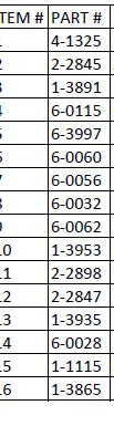
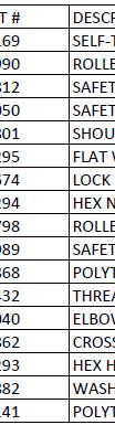
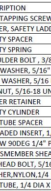
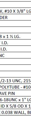
69 10.11 PARTS LIST CYLINDER ASSEMBLY P/ /N: Figure ARTS LIST - CABLE ROUTING PART # DESCRIPTION CABLE ASSY. - FRONT LEFT CABLE ASSY. - FRONT RIGHT CABLE ASSY. - REAR LEFT CABLE ASSY. - REAR RIGHT HEX. NUT, 7/8"-14 UNF, GR.8 CABLE SPACER, 2" LG (optional) FLAT WASHER, 7/8" ID CABLE SPACER, 1" LG (optional) QTY Figure 87 69
AUG 2011, REV.B
 6-4041 AUG 2011, REV.B 1. 1 2. OWNER / EMPLOYER OBLIGATIONS 1. The Owner/Employer shall ensure that lift operators are qualified and that they are trained in the safe use and operation of the lift using
4-POST LBS Q, 43102QE
 INSTALLATION and OPERATION MANUAL 4-POST 12000 LBS. 43102Q, 43102QE READ THIS INSTRUCTION MANUAL THOROUGHLY BEFORE INSTALLING, OPERATING, SERVICING OR MAINTAINING THE LIFT. SAVE THIS MANUAL. 309 EXCHANGE
14K SCISSOR LIFT Long Models: EELR787A, EELR788A, EELR789A, EELR790A Short Models: EELR783A, EELR784A, EELR785A, EELR786A
 READ THIS INSTRUCTION MANUAL THOROUGHLY BEFORE INSTALLING, OPERATING, SERVICING OR MAINTAINING THE LIFT. SAVE THIS MANUAL. INSTALLATION and OPERATION MANUAL 14K SCISSOR LIFT Long Models: EELR787A, EELR788A,
MIDRISE MODEL SM60F_1 // SM60F_A 6,500 LB. CAPACITY
 INSTALLATION and OPERATION MANUAL READ THIS INSTRUCTION MANUAL THOROUGHLY BEFORE INSTALLING, OPERATING, SERVICING OR MAINTAINING THE LIFT. SAVE THIS MANUAL. NOV 2007 REV.B MIDRISE MODEL SM60F_1 // SM60F_A
INSTALLATION AND OPERATION MANUAL
 AIR-HYDRAULIC ROLLING JACKBEAM CAPACITY: 5000 LBS. MODELS: EELR503A INSTALLATION AND OPERATION MANUAL READ ALL INSTRUCTIONS THOROUGHLY BEFORE INSTALLING, OPERATING, SERVICING, OR MAINTAINING THE LIFT.
10K ALL-IN-ONE 2 POST V-SERIES 42010DSA 42010VSA
 INSTALLATION and OPERATION MANUAL 10K ALL-IN-ONE 2 POST V-SERIES 42010DSA 42010VSA READ THIS INSTRUCTION MANUAL THOROUGHLY BEFORE INSTALLING, OPERATING, SERVICING OR MAINTAINING THE LIFT. SAVE THIS MANUAL.
MANUAL 14K S CISSOR SCISSOR LIFT
 INSTALLATION and OPERATION MANUAL 14K SCISSOR LIFT EELR137A EELR137AFM READ THIS INSTRUCTION MANUAL THOROUGHLY BEFORE INSTALLING, OPERATING, SERVICING OR MAINTAINING THE LIFT. SAVE THIS MANUAL. Snap-On
It is the shop owner's responsibility to train all operators in lift operation and safety.
 2 Your new lift will provide years of dependable service if installed, operated and maintained properly. Read and be prepared to follow all safety, installation, operation, and maintenance instructions
INSTALLATION and OPERATION MANUAL
 INSTALLATION and OPERATION MANUAL 10K 2N1 2 POST V-SERIES SV210S - R/B/M,1/3 D210S - R/B/M,1/3 READ and SAVE THIS INSTRUCTION MANUAL JUNE 2007 6-3255 Table of Contents 1.0 SAFETY AND OPERATING INSTRUCTIONS...3
Model Q4P12E and Q4P12X
 INSTALLATION, OPERATION & MAINTENANCE MANUAL Four Post Surface Mounted Lift Model Q4P2E and Q4P2X Closed Front (2,000 lb Capacity) 200 Cabel Street, P.O. Box 3972 Louisville, Kentucky 4020-3972 Email:sales@Qualitylifts.com
INSTALLATION and OPERATION MANUAL
 INSTALLATION and OPERATION MANUAL AC2012S 12,000 12,000 LB. LB. (SYMMETRICAL) READ and SAVE THIS INSTRUCTION MANUAL P.O. Box 15540 Richmond, VA 23227 804-798-8922 www.accu-turn.com 1-800-551-2228 APR 2004
Motorcycle Lift 1,000 lbs. capacity Installation, Safety, Operation, Maintenance
 Motorcycle Lift 1,000 lbs. capacity Installation, Safety, Operation, Maintenance Entire contents 2008 by RL Consolidated, Inc. All rights reserved. 994358 CO7297 Rev. F 12/17/2008 Inspection upon receipt
INSTALLATION and OPERATION MANUAL
 INSTALLATION and OPERATION MANUAL Model 42010VA 10 10000 LB. LB. (ASYMMETRICAL) READ THIS INSTRUCTION MANUAL THOROUGHLY BEFORE INSTALLING, OPERATING, SERVICING OR MAINTAINING THE LIFT. SAVE THIS MANUAL.
Drop Tail Motorcycle Lift 1,000 lbs. capacity Installation, Safety, Operation, Maintenance
 Drop Tail Motorcycle Lift 1,000 lbs. capacity Installation, Safety, Operation, Maintenance Entire contents 2009 by Direct Lift. All rights reserved. IN50012 CO7338.1 Rev. B 03/30/2009 Inspection upon receipt
Model OE Four Post Surface Mounted Lift. Office / Fax IMPORTANT: READ THIS MANUAL COMPLETELY BEFORE
 Four Post Surface Mounted Lift Model OE-40000 Open Front (,000 lb Capacity) 0 Cabel Street, P.O. Box 3944 Louisville, Kentucky 40-3944 Email:sales@challengerlifts.com Web site:www.challengerlifts.com Office
Installation Instructions Capacity 10,000 lbs. (100 Series Lift)
") Installation Instructions Capacity 10,000 lbs. (100 Series Lift) IMPORTANT Reference ANSI/ALI ALIS, Safety Requirements for Installation and Service of Automotive Lifts before installing lift. OPERATING
Installation Instructions Capacity 10,000 lbs. (100 Series Lift) IMPORTANT Reference ANSI/ALI ALIS, Safety Requirements for Installation and Service of Automotive Lifts before installing lift. OPERATING
Model Q4P12E and Q4P12X
 INSTALLATION, OPERATION & MAINTENANCE MANUAL Four Post Surface Mounted Lift Model Q4P2E and Q4P2X Closed Front (2,000 lb Capacity) 200 Cabel Street, P.O. Box 3944 Louisville, Kentucky 4020-3944 Email:sales@Qualitylifts.com
Installation, Operation & Maintenance Manual. Four Post Surface Mounted Lift. Model Open Front (15,000 lb Capacity)
") Installation, Operation & Maintenance Manual Four Post Surface Mounted Lift Model 405 Open Front (5,000 lb Capacity) 23 South Park Rd Louisville, Kentucky 40206 Email:sales@challengerlifts.com Web site:www.challengerlifts.com
Installation, Operation & Maintenance Manual Four Post Surface Mounted Lift Model 405 Open Front (5,000 lb Capacity) 23 South Park Rd Louisville, Kentucky 40206 Email:sales@challengerlifts.com Web site:www.challengerlifts.com
INSTALLATION, OPERATION & MAINTENANCE MANUAL
 INSTALLATION, OPERATION & MAINTENANCE MANUAL Four Post Surface Mounted Lift Model 4P14EFX and 4P14XFX Closed Front (14,000 lb Capacity) 200 Cabel Street, P.O. Box 3944 Louisville, Kentucky 40201-3944 Email:sales@challengerlifts.com
READ THIS MANUAL BEFORE INSTALLATION AND/OR OPERATION! WARNING:
 1 READ THIS MANUAL BEFORE INSTALLATION AND/OR OPERATION! This is a vehicle lift operation manual and no attempt is made or implied herein to instruct the user in lifting methods particular to an individual
INSTALLATION and OPERATION MANUAL
 INSTALLATION and OPERATION MANUAL 422012SS 12,000 12,000 LB. LB. (SYMMETRICAL) READ THIS INSTRUCTION MANUAL THOROUGHLY BEFORE INSTALLING, OPERATING, SERVICING OR MAINTAINING THE LIFT. SAVE THIS MANUAL.
INSTALLATION and OPERATION MANUAL
 INSTALLATION and OPERATION MANUAL EELR349A // EELR351A 10,000 10,000 LB. LB. (SYMMETRICAL) READ THIS INSTRUCTION MANUAL THOROUGHLY BEFORE INSTALLING, OPERATING, SERVICING OR MAINTAINING THE LIFT. SAVE
Drop Tail Motorcycle Lift 1,000 lbs. capacity Installation, Safety, Operation, Maintenance
 Drop Tail Motorcycle Lift 1,000 lbs. capacity Installation, Safety, Operation, Maintenance Entire contents 2011 by Vehicle Service Group. All rights reserved. IN50012 CO7932 Rev. C 04/20/2011 Inspection
Two Post Surface Mounted Lift 12,000 LBS. CAPACITY 3000 LBS. PER ARM
 INSTALLATION, OPERATION & MAINTENANCE MANUAL Two Post Surface Mounted Lift MODEL EELR537A 12,000 LBS. CAPACITY 3000 LBS. PER ARM Snap-On Equipment 309 Exchange Avenue, Conway, Arkansas, 72032 Tel: 501-450-1500
2-Post Lift Operations and Maintenance Manual
 2-Post Lift Operations and Maintenance Manual Table Of Contents Safety Instructions... 2 Owner/Employer Responsibilities / Operating Conditions... 3 Operating Instructions... 4 Maintenance Instructions...
( Series) Capacity 18,000 lbs. (9,000 lbs. per axle) Four Post Surface Mounted Lift Maximum Wheelbases: 194" & 230" Minimum Wheelbase: 126"
 Capacity 18,000 lbs. (9,000 lbs. per axle) Four Post Surface Mounted Lift Maximum Wheelbases: 194 & 230 Minimum Wheelbase: 126") LP20111 March 2015 by Vehicle Service Group. IN20195 All rights reserved. CO9223.5 Rev. L 3/24/2015 SM18 (000-017 Series) Capacity 18,000 lbs. (9,000 lbs. per axle) Four Post Surface Mounted Lift Maximum
LP20111 March 2015 by Vehicle Service Group. IN20195 All rights reserved. CO9223.5 Rev. L 3/24/2015 SM18 (000-017 Series) Capacity 18,000 lbs. (9,000 lbs. per axle) Four Post Surface Mounted Lift Maximum
INSTALLATION and OPERATION MANUAL
 INSTALLATION and OPERATION MANUAL 10K SCISSOR LIFT MODEL: 4810605_(AF, AFM, AFX, AFMX, LL, XLL) READ THIS INSTRUCTION MANUAL THOROUGHLY BEFORE INSTALLING, OPERATING, SERVICING OR MAINTAINING THE LIFT.
TWO POST LIFT INSTALLATION AND OWNERS MANUAL
 TWO POST LIFT INSTALLATION AND OWNERS MANUAL DP15, DP15-2 Capacity 15,000 lbs. 1. TABLE OF CONTENTS 2. Important Information.. 2 3. Section 1 Owner s Manual Safety Instructions... 3 Monthly Maintenance...
SM88 I N S T A L L A T I O N I N S T A L L A T I O N I N S T R U C T I O N S I N S T R U C T I O N S
 I N S T A L L A T I O N I N S T R U C T I O N S January 2005 by Rotary Lift. CO6167.2 IN30071 Rev. B 01/20/2005 I N S T A L L A T I O N I N S T R U C T I O N S LP30072 SM88 (300 Series) Four Post Surface
Installation Instructions X-Force UTV Lift (000 Series) Capacity 2,275 lbs (1,035 kg)
 Capacity 2,275 lbs (1,035 kg)") Installation Instructions X-Force UTV Lift (000 Series) Capacity 2,275 lbs (1,035 kg) Read entire manual before assembling, installing, operating, or servicing this equipment. LP20640 IN20793 September
Installation Instructions X-Force UTV Lift (000 Series) Capacity 2,275 lbs (1,035 kg) Read entire manual before assembling, installing, operating, or servicing this equipment. LP20640 IN20793 September
Installation Instructions
 Installation Instructions 2-Post Capacity 12,000 lbs. OPERATING CONDITIONS Lift is not intended for outdoor use and has an operating ambient temperature range of 41-104 F (5-40 C) IMPORTANT Reference ANSI/ALI
Installation Instructions Capacity 10,000 lbs. DP10 (200 Series Lift)
") Installation Instructions Capacity 10,000 lbs. DP10 (200 Series Lift) IMPORTANT Reference ANSI/ALI ALIS, Safety Requirements for Installation and Service of Automotive Lifts before installing lift. OPERATING
Installation Instructions Capacity 10,000 lbs. DP10 (200 Series Lift) IMPORTANT Reference ANSI/ALI ALIS, Safety Requirements for Installation and Service of Automotive Lifts before installing lift. OPERATING
INSTALLATION, OPERATION & MAINTENANCE MANUAL
 INSTALLATION, OPERATION & MAINTENANCE MANUAL Two Post Surface Mounted Lift MODEL X10 10,000 LBS. CAPACITY 2500 LBS. PER ARM 200 Cabel Street, P.O. Box 3944 Louisville, Kentucky 40201-3944 Email:sales@challengerlifts.com
Installation, Operation & Maintenance Manual. Surface Mounted Lift 10,000 LBS. CAPACITY 2500 LBS. PER ARM
 Installation, Operation & Maintenance Manual VersymmetricTM Two Post Surface Mounted Lift MODEL CL10 10,000 LBS. CAPACITY 2500 LBS. PER ARM 200 Cabel Street, P.O. Box 3944 Louisville, Kentucky 40201-3944
MODEL Two Post Surface Mounted Lift. Office / Fax Installation, Operation & Maintenance Manual
 Installation, Operation & Maintenance Manual Two Post Surface Mounted Lift MODEL 15000 15,000 LB CAPACITY - 3750 LB PER ARM MODEL 18000 18,000 LB CAPACITY 4500 LB PER ARM 200 Cabel Street, P.O. Box 3944
2-POST 10,000 LB. (ASYMMETRICAL)
") INSTALLATION and OPERATION MANUAL 2-POST 42010CA / 42010CA14 10,000 LB. (ASYMMETRICAL) READ THIS INSTRUCTION MANUAL THOROUGHLY BEFORE INSTALLING, OPERATING, SERVICING OR MAINTAINING THE LIFT. SAVE THIS
INSTALLATION and OPERATION MANUAL 2-POST 42010CA / 42010CA14 10,000 LB. (ASYMMETRICAL) READ THIS INSTRUCTION MANUAL THOROUGHLY BEFORE INSTALLING, OPERATING, SERVICING OR MAINTAINING THE LIFT. SAVE THIS
ATTENTION. 1. Do not attempt to use the power unit to extend your cylinder. This must be done manually.
 NSS8XLT Installation Manual ATTENTION By following the instructions in this manual you can save yourself much time, frustration and money. The installation of your lift will take 4-5 hours. Do not rush.
Four Post Surface Mounted Lift Capacity 14,000 lbs. (7,000 lbs. per axle)
") Four Post Surface Mounted Lift Capacity 14,000 lbs. (7,000 lbs. per axle) July 2014 by Vehicle Service Group. All rights reserved. LP60032 CO8906.8 IN60032 Rev. A 7/25/2014 INSTALLATION INSTRUCTION 4'-6"
Four Post Surface Mounted Lift Capacity 14,000 lbs. (7,000 lbs. per axle) July 2014 by Vehicle Service Group. All rights reserved. LP60032 CO8906.8 IN60032 Rev. A 7/25/2014 INSTALLATION INSTRUCTION 4'-6"
Challenger Lifts, Inc. MODEL 12000
 Challenger Lifts, Inc. MODEL 12000 TWO POST SURFACE MOUNTED LIFT OPERATION, INSTALLATION & MAINTENANCE MANUAL IMPORTANT READ THIS MANUAL COMPLETELY BEFORE INSTALLING OR OPERATING THE LIFT 200 CABEL STREET,
If facility voltage is different, refer to set-up instructions. IMPORTANT This lift is wired and adjusted to operate at 230 volts.
 MODEL 40/50K Installation And Owner s Manual (000Series) Capacity 40,000 lbs. (20,000 lbs. per axle) Capacity 50,000 lbs. (25,000 lbs. per axle) Four Post Surface Mounted Lift IMPORTANT This lift is wired
MODEL QMR6 PORTABLE MID-RISE LIFT 6,000 lb Capacity 1500 lb Per Arm INSTALLATION, OPERATION AND MAINTENANCE MANUAL
 MODEL QMR6 PORTABLE MID-RISE LIFT 6,000 lb Capacity 1500 lb Per Arm INSTALLATION, OPERATION AND MAINTENANCE MANUAL IMPORTANT!!! READ THIS MANUAL COMPLETELY BEFORE INSTALLING OR OPERATING THE LIFT 200 CABEL
10K ALL-IN-ONE 2 POST V-SERIES 42010DSA 42010VSA
 INSTALLATION and OPERATION MANUAL 10K ALL-IN-ONE 2 POST V-SERIES 42010DSA 42010VSA READ THIS INSTRUCTION MANUAL THOROUGHLY BEFORE INSTALLING, OPERATING, SERVICING OR MAINTAINING THE LIFT. SAVE THIS MANUAL.
ATD2P11BS. Two-Post Clear Floor Bi-Symmetric Automotive Lift. Installation & Operation Manual. 11,000 lbs. Capacity. (2,750 lbs.
 Two-Post Clear Floor Bi-Symmetric Automotive Lift 11,000 lbs. Capacity (2,750 lbs. Max per Arm) Installation & Operation Manual 1. Safety Information 1.1 Note, Caution and Warning 1.2 Important Information
MODEL CL10. Versymmetric Two Post. Surface Mounted Lift. Installation, Operation & Maintenance Manual
 Installation, Operation & Maintenance Manual Versymmetric Two Post Surface Mounted Lift MODEL CL10 10,000 LBS. CAPACITY 2500 LBS. PER ARM 200 Cabel Street, P.O. Box 3944 Louisville, Kentucky 40201-3944
CR30 Installation Instruction Capacity 30,000 lbs. (15,000 lbs. per axle) 235 /271 /308 Wheelbases 140 Minimum Wheelbase
 235 /271 /308 Wheelbases 140 Minimum Wheelbase") CR0 Installation Instruction Capacity 0,000 lbs. (,000 lbs. per axle) /7 /08 Wheelbases 40 Minimum Wheelbase January 009 CO70 INS0449 Rev. - /08/009 Required Clearances REAR 8' 0" Min. To Nearest Obstruction
CR0 Installation Instruction Capacity 0,000 lbs. (,000 lbs. per axle) /7 /08 Wheelbases 40 Minimum Wheelbase January 009 CO70 INS0449 Rev. - /08/009 Required Clearances REAR 8' 0" Min. To Nearest Obstruction
Models Q4P07. Four Post Surface Mounted Lift. Installation, Operation & Maintenance Manual IMPORTANT: READ THIS MANUAL COMPLETELY BEFORE
 Installation, Operation & Maintenance Manual Four Post Surface Mounted Lift Models Q4P07 (7,000 lb Capacity) 200 Cabel Street, P.O. Box 3972, Louisville, Kentucky 40201-3972 Email:sales@qualitylifts.com
INSTALLATION and OPERATION MANUAL
 INSTALLATION and OPERATION MANUAL 10K SCISSOR LIFT MODEL: EELR3 A (58/59/60/61) READ THIS INSTRUCTION MANUAL THOROUGHLY BEFORE INSTALLING, OPERATING, SERVICING OR MAINTAINING THE LIFT. SAVE THIS MANUAL.
SPO15, SPO18 I N S T A L L A T I O N I N S T R U C T I O N S
 SPO15, SPO18 Sprinter SPO15 (3A0 Lifts) Capacity 11,000 lbs. Standard SPO15 (300 Series Lifts) Capacity 15,000 lbs. Standard SPO18 (300 Series Lifts) Capacity 18,000 lbs. SPO15 (31A0 Lifts) Capacity 14,300
Two Post Surface Mounted Lift 10,000 LBS. CAPACITY 2500 LBS. PER ARM
 INSTALLATION, OPERATION & MAINTENANCE MANUAL Two Post Surface Mounted Lift MODEL LE10 10,000 LBS. CAPACITY 2500 LBS. PER ARM 2311 South Park Rd Louisville, Kentucky 40219 Email:sales@challengerlifts.com
Challenger Lifts, Inc. MODELS & 18000
 Challenger Lifts, Inc. MODELS 15000 & 18000 TWO POST SURFACE MOUNTED LIFT OPERATION, INSTALLATION & MAINTENANCE MANUAL IMPORTANT READ THIS MANUAL COMPLETELY BEFORE INSTALLING OR OPERATING THE LIFT 200
Two Post Surface Mounted Lift 12,000 LBS. CAPACITY 3000 LBS. PER ARM
 INSTALLATION, OPERATION & MAINTENANCE MANUAL Two Post Surface Mounted Lift MODEL Q12 12,000 LBS. CAPACITY 3000 LBS. PER ARM 200 Cabel Street, P.O. Box 3944, Louisville, Kentucky 40206 Email:sales@qualitylifts.com
CONTENTS. Product Features and Specifications Installation Requirement Installation Exploded View Operation Instruction...
 1 CONTENTS Product Features and Specifications... 3 Installation Requirement... 5 Installation... 6 Exploded View... 20 Test... 22 Operation Instruction... 25 Maintenance... 26 Trouble Shooting... 27 Parts
SPOA10NB, SPOA10, SPO10 ( Series Lifts) SPOA7, SPOA9, SPO9 (500 Series Lifts)
 SPOA7, SPOA9, SPO9 (500 Series Lifts)") O PE SPOA10NB, SPOA10, SPO10 (200-700 Series Lifts) SPOA7, SPOA9, SPO9 (500 Series Lifts) SPOA7 Capacity 7,000 lbs. SPOA9, SPO9 Capacity 9,000 lbs. SPOA10NB, SPOA10, SPO10 Capacity 10,000 lbs. R A TI O
O PE SPOA10NB, SPOA10, SPO10 (200-700 Series Lifts) SPOA7, SPOA9, SPO9 (500 Series Lifts) SPOA7 Capacity 7,000 lbs. SPOA9, SPO9 Capacity 9,000 lbs. SPOA10NB, SPOA10, SPO10 Capacity 10,000 lbs. R A TI O
AR123/SM123 I N S T A L L A T I O N I N S T A L L A T I O N I N S T R U C T I O N S I N S T R U C T I O N S
 February 2005 by Rotary Lift. All rights reserved. CO6167.3 I N S T A L L A T I O N I N S T R U C T I O N S IN30069 Rev. E 02/10/2005 I N S T A L L A T I O N I N S T R U C T I O N S LP30068 AR123/SM123
Models Q4P09H & Q4P09X
 Installation, Operation & Maintenance Manual Four Post Surface Mounted Lift Models Q4P09H & Q4P09X (9,000 lb Capacity) 200 Cabel Street, P.O. Box 3944 Louisville, Kentucky 40201-3944 Email:sales@qualitylifts.com
CR18 Installation Instructions
 CR8 Installation Instructions Capacity 8,000 lbs. (9,000 lbs. per axle) Four Post Surface Mounted Lift Maximum Wheelbases: 94" & 0" Minimum Wheelbase: 6" August 0 by Vehicle Service Group. IN6008 All rights
TWO POST LIFT INSTALLATION AND OWNERS MANUAL. January 2008 rev. E I MAN
 TWO POST LIFT INSTALLATION AND OWNERS MANUAL DP15, DP15-2 Capacity 15,000 lbs. January 2008 rev. E 1. TABLE OF CONTENTS 2. Important Information.. 2 3. Section 1 Owner s Manual Safety Instructions... 3
9,000 LBS. CAPACITY 2250 LBS. PER ARM
 INSTALLATION NSTALLATION,, OPERATION O & MAINTENANCE M MANUAL & M VersymmetricTM Two Post Surface Mounted Lift MODEL CL9 9,000 LBS. CAPACITY 2250 LBS. PER ARM 200 Cabel Street, P.O. Box 3944 Louisville,
MODEL CL10. Versymmetric Two Post. Surface Mounted Lift. Installation, Operation & Maintenance Manual
 Installation, Operation & Maintenance Manual Versymmetric Two Post Surface Mounted Lift MODEL CL10 10,000 LBS. CAPACITY 2500 LBS. PER ARM 200 Cabel Street, P.O. Box 3944 Louisville, Kentucky 40201-3944
MID RISE. INSTALLATION and OPERATION MANUAL MODEL 6000A // 6000E 6,000 LB. CAPACITY. READ and SAVE THIS INSTRUCTION MANUAL
 INSTALLATION and OPERATION MANUAL MID RISE MODEL 6000A // 6000E 6,000 LB. CAPACITY READ and SAVE THIS INSTRUCTION MANUAL AUGUST 2005 6-0944 6500 Millcreek Drive Mississauga, Ontario Canada L5N 2W6 1-800-268-7959
INSTALLATION and OPERATION
 INSTALLATION and OPERATION MANUAL 422012SS14 12,000 LB. (SYMMETRICAL) READ THIS INSTRUCTION MANUAL THOROUGHLY BEFORE INSTALLING, OPERATING, SERVICING OR MAINTAINING THE LIFT. SAVE THIS MANUAL. 309 EXCHANGE
MODEL QFP09. Two Post Surface Mounted Lift. Installation, Operation & Maintenance Manual. Office / Fax
 Installation, Operation & Maintenance Manual Two Post Surface Mounted Lift MODEL QFP09 9,000 LBS. CAPACITY 2,250 LBS. PER ARM 200 Cabel Street, P.O. Box 3972 Louisville, Kentucky 40201-3972 Email:sales@qualitylifts.com
INSTALLATION and OPERATION MANUAL
 INSTALLATION and OPERATION MANUAL 10K SCISSOR LIFT MODEL: 10605A_(F,FM,FX,FMX) READ THIS INSTRUCTION MANUAL THOROUGHLY BEFORE INSTALLING, OPERATING, SERVICING OR MAINTAINING THE LIFT. SAVE THIS MANUAL.
MODEL CL10. VersymmetricTM Two Post. Surface Mounted Lift. Installation, Operation, & Maintenance Manual
 Installation, Operation, & Maintenance Manual VersymmetricTM Two Post Surface Mounted Lift MODEL CL10 WITH DUAL PENDANT CONTROL 10,000 LBS. CAPACITY 2500 LBS. PER ARM 200 Cabel Street, P.O. Box 3944 Louisville,
ATO7 (100 Series Lifts)
") O PE ATO7 (100 Series Lifts) Capacity 7000 lbs. (3181 kg) 1750 lbs. (795.25 kg) per arm R A TI O N & M AI N TE N A N N CE Table Of Contents Safety Instructions... 2 Owner/Employer Responsibilities / Operating
O PE ATO7 (100 Series Lifts) Capacity 7000 lbs. (3181 kg) 1750 lbs. (795.25 kg) per arm R A TI O N & M AI N TE N A N N CE Table Of Contents Safety Instructions... 2 Owner/Employer Responsibilities / Operating
Lifting height 5.5" - 72" with adapters " Height overall 165" Width between columns 122" Drive through 109" Width overall 151.
 Model Number TP12KC-D Capacity 12,000 lbs. Lifting height 5.5" - 72" with adapters 79.625" Height overall 165" Width between columns 122" Drive through 109" Width overall 151.125" Arm extension 37.5" -
EZ LINER EXPRESS USERS MANUAL
 EZ LINER EXPRESS 2013 Vehicle Service Group CHIEF'S LIMITED ONE-YEAR WARRANTY & LIABILITY Chief Automotive Technologies warrants for one year from date of installation and/or purchase any components of
INSTALLATION and OPERATION
 INSTALLATION and OPERATION MANUAL 422012SS 12,000 LB. (SYMMETRICAL) READ THIS INSTRUCTION MANUAL THOROUGHLY BEFORE INSTALLING, OPERATING, SERVICING OR MAINTAINING THE LIFT. SAVE THIS MANUAL. 309 EXCHANGE
TP12KC-DX. Two Post Clear Floor. Automotive Lift. 12,000 lb. Capacity. (3,000 lbs. Max Capacity per Arm) Installation & Operation Manual
 Installation & Operation Manual") Two Post Clear Floor Automotive Lift 12,000 lb. Capacity (3,000 lbs. Max Capacity per Arm) Installation & Operation Manual IMPORTANT!! READ MANUAL THOROUGHLY BEFORE INSTALLING, OPERATING, SERVICING OR
Two Post Clear Floor Automotive Lift 12,000 lb. Capacity (3,000 lbs. Max Capacity per Arm) Installation & Operation Manual IMPORTANT!! READ MANUAL THOROUGHLY BEFORE INSTALLING, OPERATING, SERVICING OR
9,000 POUND TWO-COLUMN AUTOMOTIVE LIFT Model: NW-2-9KFP MANUAL
 9,000 POUND TWO-COLUMN AUTOMOTIVE LIFT Model: NW-2-9KFP MANUAL 1 9,000 POUND CAPACITY MODEL: NW-2-9KFP TWO-COLUMN AUTOMOTIVE LIFT READ THIS ENTIRE MANUAL BEFORE OPERATION BEGINS RECORD BELOW THE FOLLOWING
SL210i/SL212i/SL19i. Table Of Contents
 SL210i/SL212i/SL19i (700 Series) SL19i Capacity 9,000 lbs. SL210i Fixed Pad Capacity 9,000 lbs. SL210i Capacity 10,000 lbs. SL212i Capacity 12,000 lbs. Table Of Contents Owner/Employer Responsibilities...
Floor Plate Style Lift And Overhead Beam Style Lift. Two Post Lift
 Floor Plate Style Lift And Overhead Beam Style Lift 9,000 POUND Two Post Lift ASSEMBLY & OPERATION INSTRUCTION TABLE OF CONTENTS Important Note Page 3 Definition Page 4 Preparation and General Information
JEEVES. JEEVES Installation Manual. Installation Manual The Easiest Do-It-Yourself Dumbwaiter on the Market
 1 888-323-8755 www.nwlifts.com JEEVES Installation Manual The Easiest Do-It-Yourself Dumbwaiter on the Market This manual will cover the installation procedure step-by-step. The installation of this dumbwaiter
Installation Instructions Table of Contents
 Installation Instructions Table of Contents Pre- Installation of Garage Storage Lift 2 Layout the Garage Storage Lift 3 Installing the strut Channels 3 Install the Drive Assembly 5 Install the Drive Shaft
SCISSOR LIFT Model MR6K-38 /161108A 6,000lb Capacity Operation Manual
 SCISSOR LIFT Model MR6K-38 /161108A 6,000lb Capacity Operation Manual (Version A) 2009. Apr. CONTENT 1. Safety Note, Caution and Warning Important Information Safety Instructions 2. Technical Manual Product
INSTALLATION, OPERATION & MAINTENANCE MANUAL
 INSTALLATION, OPERATION & MAINTENANCE MANUAL Four Post Surface Mounted Lift/Platform Lube Rack System MODEL MDTR3 SHOWN (RECESSED TRIPLE) Model MDT Modular Drive Thru (12,000 lb Capacity) 200 Cabel Street,
T R I N S I N S U C N S
 R O TA R Y V A L I D A T E D CERTIFIED B Y E L T SPOA7, SPOA9, SPO9 Two Post Surface Mounted Lift (200 Series Lifts) SPOA7 Capacity 7,000lbs. SPOA9 Capacity 9,000lbs. 1750 lbs. per arm 2250 lbs. per arm
Z-Gate Universal Shifter
 Installation Instructions Z-Gate Universal Shifter Fits: GM, Ford, Lincoln and Chrysler Transmissions See Application Guide for Specific Applications Part #80681 Rev 06/01/2018 WORK SAFELY! For maximum
WHIP INDUSTRIES, INC.
 WHIP INDUSTRIES, INC. WFP30R, WFP30R-E & WFP30R-EE STD., EXT. & E-EXT. 30,000 LBS CAPACITY FOUR POST ABOVE GROUND LIFT INSTALLATION INSTRUCTIONS & MANUAL WHIP INDUSTRIES, INC 3010 S MAIN ST. FORT WORTH,
Installation Instructions Z-Gate Shifter
 Installation Instructions Z-Gate Shifter Part Number 80681 1998, 2001 by B&M Racing and Performance Products The B&M Z-Gate shifter can be used in vehicles equipped with most popular three speed automatic
Light Truck MegaShifter
 Installation Instructions Light Truck MegaShifter The B&M Light Truck Megashifter shifter is designed to be used in most light trucks equipped with most popular three speed or four speed automatic transmissions.
CONTENTS. Product Features and Specifications...1. Installation Requirement...3. Steps of Installation...4. Exploded View Test Run...
 TP10AS 2-POST LIFT CONTENTS Product Features and Specifications...1 Installation Requirement...3 Steps of Installation...4 Exploded View...24 Test Run....28 Operation Instruction...29 Maintenance...30
INSTRUCTION MANUAL 16K - Fifth Wheel Hitch
 You can take it with you. INSTRUCTION MANUAL 16K - Fifth Wheel Hitch Product No. 30047 DEALER/INSTALLER: END USER: (1) Provide this Manual to end user. (2) Physically demonstrate hitching and unhitching
8700 Series 8900 Series Rolling Air Jacks
 8700 Series 8900 Series Rolling Air Jacks Installation, Operation & Repair Parts Information - NOTICE - AIR SUPPLY MUST HAVE IN-LINE FILTER/REGULATOR/LUBRICATOR (NOT INCLUDED) TO VALIDATE THE ROLLING AIR
TWO POST LIFT INSTALLATION AND OWNERS MANUAL Capacity 10,000 lbs.
 TWO POST LIFT INSTALLATION AND OWNERS MANUAL Capacity 10,000 lbs. May 2009 All rights reserved. CO7378.2 IN60005 Rev. - 5/7/2009 TABLE OF CONTENTS Important Information...2 Section 1 Owner s Manual Safety
FOUR-POST LIFT. 14,000 lbs. Capacity
 FOUR-POST LIFT 14,000 lbs. Capacity Note: At the rated capacity of 14,000 lbs. lift was designed for: 101" Minimum wheelbase for models without rolling jacks 124" Minimum wheelbase for models with rolling
Cargolift 85 Pv Repair. Cargolift 90 Sa Standard. Cargolift 120 Saav Jumbo. Cargolift 120 F Drive-on IMPORTANT
 Installation, Operation and Maintenance Manual For Cargolift 85 Pv Repair Cargolift 90 Sa Standard Cargolift 120 Saav Jumbo Cargolift 120 F Drive-on IMPORTANT Read this manual throughoutly before installing,
Models Q4P09H, Q4P09X & Q4P09W
 Installation, Operation & Maintenance Manual Four Post Surface Mounted Lift Models Q4P09H, Q4P09X & Q4P09W (9,000 lb Capacity) 200 Cabel Street, P.O. Box 3972, Louisville, Kentucky 40201-3972 Email:sales@qualitylifts.com
BLAZER 9000 LUBE LIFT OPERATOR AND PARTS MANUAL
 BLAZER 9000 LUBE LIFT OPERATOR AND PARTS MANUAL Blazer 9000 Lube Lift Operator s Manual Note: Instructions must be read thoroughly before installing, operating, or maintaining the lift. Devon Lube Center
PP8S Four Post Lift 8,000 lbs. Capacity
 PP8S Four Post Lift 8,000 lbs. Capacity (4,000 lbs. per axle) Minimum wheelbase 100" at rated capacity IMPORTANT INSTALLATION / OWNERS MANUAL Read this manual thoroughly before installing, operating, or
TWO POST LIFT INSTALLATION AND OWNERS MANUAL Capacity 10,000 lbs.
 TWO POST LIFT INSTALLATION AND OWNERS MANUAL Capacity 10,000 lbs. October 2012 by Vehicle Service Group All rights reserved. CO8347 IN60009 Rev. H 10/18/2012 TABLE OF CONTENTS Important Information...2
CONTENTS. Product Features and Specifications Installation Requirement Steps of Installation 4. Exploded View Test Run...
 CONTENTS Product Features and Specifications... 1 Installation Requirement... 3 Steps of Installation 4 Exploded View... 14 Test Run... 16 Operation Instruction... 19 Maintenance... 20 Trouble Shooting...
CONTENTS. Product Features and Specifications...1. Installation Requirement Steps of Installation.. 5. Exploded View Test Run...
 CONTENTS Product Features and Specifications...1 Installation Requirement... 3 Steps of Installation.. 5 Exploded View...18 Test Run...21 Operation Instruction...22 Maintenance... 23 Trouble Shooting...
Atlas PV-9WP Addendum
 Atlas PV-9WP Addendum 9,000 lb. Capacity Two-Post Overhead Lift The Atlas PV-9WP above ground hoist is 6 inches wider than the Atlas PV-9P, giving it an overall width of 141 (11 9 ) and a drive thru width
INSTALLATION INSTRUCTION 88094
 INSTALLATION INSTRUCTION 88094 FOR RANCHO SUSPENSION SYSTEM RS6594B 4WD & 2WD NISSAN TITAN READ ALL INSTRUCTIONS THOROUGHLY FROM START TO FINISH BEFORE BEGINNING INSTALLATION Rev D IMPORTANT NOTES! WARNING:
Installation Instructions. QuickSilver Shifter. Fits: GM, Ford, Chrysler Transmissions See Application Guide for Specific Applications Part # 80683
 Installation Instructions QuickSilver Shifter Fits: GM, Ford, Chrysler Transmissions See Application Guide for Specific Applications Part # 80683 WORK SAFELY! For maximum safety, perform this installation
Installation Instructions Sport Shifter
 The B&M Sport Shifter can be used in vehicles equipped with most popular three speed or four speed automatic transmissions. It is equipped with neutral safety and backup light switches, transmission brackets
INSTALLATION / OWNERS MANUALS
 Floor Plate Automotive Lift 9,000 POUND CAPACITY IMPORTANT Reference ANSI/ALI ALIS, Safety Requirements for Installation and Service of Automotive Lifts before installing lift. INSTALLATION / OWNERS MANUALS
IMPORTANT INFORMATION
 TABLE OF CONTENTS IMPORTANT INFORMATION... 2 LIFT AREA LAYOUT INFORMATION... 3 TOOLS and EQUIPMENT REQUIRED FOR INSTALL... 4 INSTALLATION PROCEDURE... 5 FOUNDATION and ANCHORING REQUIREMENTS... 6 DEFINITION
Installation Instructions Right Hand Drive Megashifter
 Installation Instructions Right Hand Drive Megashifter Part Number 80685 1995, 2001, 2006, 2010 by B&M Racing & Performance Products The B&M Right Hand Drive Megashifter is designed specifically for vehicles