UF E
|
|
|
- Bridget Dalton
- 6 years ago
- Views:
Transcription
1 UF E
2 FOREWORD This manual contains an introductory description on the SUZUKI UF50/UF50Z and procedures for its inspection, service, and overhaul of its main components. Other information considered as generally known is not included. Read the GENERAL INFORMATION section to familiarize yourself with the motorcycle and its maintenance. Use this section as well as other sections as a guide for proper inspection and service. This manual will help you know the motorcycle better so that you can assure your customers of fast and reliable service. This manual has been prepared on the basis of the latest specifications at the time of publication. If modifications have been made since then, differences may exist between the content of this manual and the actual motorcycle. Illustrations in this manual are used to show the basic principles of operation and work procedures. They may not represent the actual motorcycle exactly in detail. This manual is written for persons who have enough knowledge, skills and tools, including special tools, for servicing SUZUKI motorcycles. If you do not have the proper knowledge and tools, ask your authorized SUZUKI motorcycle dealer to help you. GROUP INDEX GENERAL INFORMATION PERIODIC MAINTENANCE ENGINE FUEL AND LUBRICATION SYSTEM CHASSIS ELECTRICAL SYSTEM SERVICING INFORMATION UF50K1 AND UF50ZK1 ( 01-MODEL) Inexperienced mechanics or mechanics without the proper tools and equipment may not be able to properly perform the services described in this manual. Improper repair may result in injury to the mechanic and may render the motorcycle unsafe for the rider and passenger. COPYRIGHT SUZUKI MOTOR ESPAÑA, S.A. 2000
3 HOW TO USE THIS MANUAL TO LOCATE WHAT YOU ARE LOOKING FOR: 1. The text of this manual is divided into sections. 2. The section titles are listed in the GROUP INDEX. 3. Holding the manual as shown at the right will allow you to find the first page of the section easily. 4. The contents are listed on the first page of each section to help you find the item and page you need. COMPONENT PARTS AND WORK TO BE DONE Under the name of each system or unit, is its exploded view. Work instructions and other service information such as the tightening torque, lubricating points and locking agent points, are provided. Example: Front wheel 1 Front axle 2 Spacer 3 Brake disc 4 Bearing 5 Front wheel 6 Spacer 7 Speedometer gearbox A Front axle nut B Brake disc bolt ITEM N m kgf-m A B
4 SYMBOL Listed in the table below are the symbols indicating instructions and other information necessary for servicing. The meaning of each symbol is also included in the table. SYMBOL DEFINITION SYMBOL DEFINITION Torque control required. Data beside it indicates specified torque. Apply or use brake fluid. Indicates service data. Measure in voltage range. Apply oil. Use engine oil unless otherwise specified. Measure in resistance range. Apply SUZUKI SUPER GREASE A. Measure in current range Apply SUZUKI MOLY PASTE. Measure in diode test range Apply THREAD LOCK Measure in continuity test range Apply THREAD LOCK SUPER Use special tool Apply THREAD LOCK SUPER
5 GENERAL INFORMATION GENERAL INFORMATION CONTENTS WARNING/CAUTION/NOTE GENERAL PRECAUTIONS SUZUKI UF50Y/UF50ZY (2000-MODEL) SERIAL NUMBER LOCATION FUEL AND OIL RECOMMENDATIONS FUEL ENGINE OIL FINAL GEAR OIL BRAKE FLUID BREAK-IN PROCEDURES INFORMATION LABELS SPECIFICATIONS
6 1-2 GENERAL INFORMATION WARNING/CAUTION/NOTE Please read this manual and follow its instructions carefully. To emphasize special information, the symbol and the words WARNING, CAUTION and NOTE have special meanings. Pay special attention to the messages highlighted by these signal words. Indicates a potential hazard that could result in death or injury. Indicates a potential hazard that could result in motorcycle damage. NOTE: Indicates special information to make maintenance easier or instructions clearer. Please note, however, that the warnings and cautions contained in this manual cannot possibly cover all potential hazards relating to the servicing, or lack of servicing, of the motorcycle. In addition to the WARN- INGS and CAUTIONS stated, you must use good judgement and basic mechanical safety principles. If you are unsure about how to perform a particular service operation, ask a more experienced mechanic for advice. GENERAL PRECAUTIONS Proper service and repair procedures are important for the safety of the service mechanic and the safety and reliability of the motorcycle. When two or more persons work together, pay attention to the safety of each other. When it is necessary to run the engine indoors, make sure that exhaust gas is forced outdoors. When working with toxic or flammable materials, make sure that the area you work in is well ventilated and that you follow all of the manufacturer s instructions. Never use gasoline as a cleaning solvent. To avoid getting burned, do not touch the engine, engine oil, and exhaust system until they have cooled. After servicing the fuel, oil, exhaust or brake systems, check all of the lines, and fittings related to the system for leaks.
7 GENERAL INFORMATION 1-3 If parts replacement is necessary, replace the parts with SUZUKI Genuine Parts or their equivalent. When removing parts that are to be reused, keep them arranged in an orderly manner so that they may be reinstalled in the proper order. Be sure to use special tools when instructed. Make sure that all parts used in reassembly are clean. Lubricate them when specified. Use the specified lubricants, bonds, or sealants. When removing the battery, disconnect the - battery lead wire first, then the + battery lead wire. When reconnecting the battery, connect the + battery lead wire first, then the - battery lead wire. Finally, cover the + battery terminal with the terminal cover. When performing service to electrical parts, disconnect the - battery lead wire, unless the service procedure requires the battery power. When tightening cylinder head and crankcase nuts and bolts, tighten the larger sizes first. Always tighten the nuts and bolts from the inside working out, diagonally and to the specified torque. Whenever you remove oil seals, gaskets, packing, O-rings, self-locking nuts, locking washers, cotter pins, circlips, and other specified parts, be sure to replace them with new ones. Also, before installing these new parts, be sure to remove any left over material from the mating surfaces. Never reuse a circlip. When installing a new circlip, take care not to expand the end gap larger than required to slip the circlip over the shaft. After installing a circlip, always ensure it is completely seated in its groove and securely fitted. Use a torque wrench to tighten fasteners to the specified torque. Wipe off grease and oil if a thread is smeared with them. After reassembling, check parts for tightness and proper operation. To protect the environment, do not unlawfully dispose of used motor oil, all other fluids, batteries, and tires. To protect the earth s natural resources, properly dispose of used motorcycles and parts.


8 1-4 GENERAL INFORMATION SUZUKI UF50Y/UF50ZY (2000-MODEL) RIGHT SIDE LEFT SIDE * Difference between photographs and the actual motorcycles depends on the markets. SERIAL NUMBER LOCATION The frame serial number or V.I.N. (Vehicle Identification Number) 1 is stamped on the right side of the steering head pipe. The engine serial number 2 is located on the end of the crankcase. These numbers are required especially for registering the machine and ordering spare parts. 1 2 FUEL AND OIL RECOMMENDATIONS Be sure to use the specified fuel and oils. Fuel and oil specifications are listed below. FUEL Use unleaded gasoline that is graded 91 octane or higher rated by the Research Method. 3 Fuel tank cap ENGINE OIL Use SUZUKI CCI SUPER OIL or an equivalent premium quality 2-stroke synthetic engine oil. Use only oils which are rated FC under the JASO classification. 4 Engine oil tank cap 3 4
9 GENERAL INFORMATION 1-5 FINAL GEAR OIL Use a good quality SAE 10W-40 multigrade motor oil. BRAKE FLUID Specification and classification: DOT 4 This motorcycle uses a glycol-based brake fluid. Do not use or mix other types of brake fluid such as silicone-based and petroleum-based fluids for refilling the system, otherwise serious damage will result to the brake system. Do not use any brake fluid taken from old, used, or unsealed containers. Do not reuse brake fluid left over from the last servicing or which has been stored for a long period of time. BREAK-IN PROCEDURES During manufacturing only the best possible materials are used and all machined parts are finished to a very high standard. It is still necessary to allow the moving parts to BREAK-IN before subjecting the engine to maximum stresses. The future performance and reliability of the engine depends on the care and restraint exercised during its early life. Refer to the following break-in engine speed recommendations. Keep to these break-in throttle positions during the break-in period. Break-in throttle position Initial 800 km: Less than 1/2 throttle Up to km: Less than 3/4 throttle Upon reaching an odometer reading of km you can subject the motorcycle to full throttle operation, for short periods of time.
10 1-6 GENERAL INFORMATION INFORMATION LABELS Loading cap label General warning label Tire information label Engine starting label Battery caution label
11 GENERAL INFORMATION 1-7 SPECIFICATIONS DIMENSIONS AND DRY MASS Overall length mm Overall width mm Overall height mm Wheelbase mm Ground clearance mm Seat height mm Dry mass kg ENGINE Type... Two-stroke, forced air-cooled Intake system... Reed valve Number of cylinders... 1 Bore mm Stroke mm Piston displacement cm 3 Corrected compression ratio :1 Carburetor... KEIHIN PWS14 Air cleaner... Polyurethane foam element Starter system... Electric and kick Lubrication system... SUZUKI CCI TRANSMISSION Clutch... Dry shoe, automatic, centrifugal type Gearshifting... Automatic, variable ratio Gear ratios... Variable reduction ratio... ( ) Final reduction ratio (51/15) (65/16) Drive system... V-belt drive
12 1-8 GENERAL INFORMATION CHASSIS Front suspension... Inverted telescopic, coil spring Rear suspension... Swingarm type, coil spring, oil damped Steering angle (right & left) Caster Trail mm Turning radius m Front brake... Disc brake Rear brake... Internal expanding Front tire size / L Rear tire size / L ELECTRICAL Ignition type... Electronic ignition (CDI) Spark plug... NGK: BPR7HS or DENSO: W22FPR Battery V 14.4 kc (4 Ah)/10 HR Generator... Generator Fuse A Headlight V 35/35 W Brake light/taillight V 21/5 W Turn signal light V 10 W CAPACITIES Fuel tank L Engine oil tank L Final gear oil ml NOTE: These specifications are subject to change without notice.
13 PERIODIC MAINTENANCE PERIODIC MAINTENANCE 2-1 CONTENTS PERIODIC MAINTENANCE SCHEDULE PERIODIC MAINTENANCE CHART MAINTENANCE AND TUNE-UP PROCEDURE BATTERY AIR CLEANER CYLINDER HEAD AND CYLINDER SPARK PLUG CARBURETOR FUEL LINE FINAL GEAR OIL BRAKES BRAKE HOSE BRAKE FLUID STEERING FRONT FORK REAR SUSPENSION TIRES CYLINDER HEAD NUTS AND EXHAUST PIPE NUT AND BOLT CHASSIS NUTS AND BOLTS GENERAL LUBRICATION AUTOMATIC CLUTCH INSPECTION INITIAL ENGAGEMENT CLUTCH LOCK-UP
14 2-2 PERIODIC MAINTENANCE PERIODIC MAINTENANCE SCHEDULE The chart below lists the recommended intervals for all the required periodic service work necessary to keep the motorcycle operating at peak performance and economy. Maintenance intervals are expressed in terms of kilometers and months, and are dependent on whichever comes first. NOTE: More frequent servicing may be performed on motorcycles that are used under severe conditions. PERIODIC MAINTENANCE CHART Interval km Initial Every Every Item months Battery I I Air cleaner C C Cylinder head and cylinder C C Spark plug C R Carburetor I I I Fuel line I I I Replace every four years. Final gear oil I I Brakes I I I Brake hose I I Replace every four years. Brake fluid I I Replace every two years. Steering I I I Front fork I Rear suspension I Tires I I I Cylinder head nuts and exhaust pipe nut and bolt T T T Chassis nuts and bolts T T T NOTE: I : Inspect and clean, adjust, lubricate, or replace as necessary. C : Clean R : Replace T : Tighten
15 PERIODIC MAINTENANCE 2-3 MAINTENANCE AND TUNE-UP PROCEDURE This section describes the servicing procedures for each item mentioned in the periodic maintenance chart on the previous page. BATTERY Inspect every km (6 months). Remove the battery holder cover. ( 6-30) First, disconnect the - battery lead wire, and then disconnect the + battery lead wire. Check the electrolyte level. It should be within the UPPER LEVEL and LOWER LEVEL lines. If the electrolyte is below the LOWER LEVEL line, add distilled water to the UPPER LEVEL line. Use a hydrometer 1 to measure the specific gravity of the electrolyte. UPPER LEVEL LOWER LEVEL : Hydrometer A specific gravity reading of 1.22 (at 20 C) or less means that the battery needs to be recharged. Remove the battery from the motorcycle and charge it with a battery charger. Standard specific gravity: at 20 C When removing the battery from the motorcycle, be sure to disconnect the - battery lead wire first. Never charge a battery while it is still in the motorcycle, as damage may result to the battery or regulator/rectifier. Be careful not to bend, obstruct, or change the routing of the battery breather hose. Make sure that the battery breather hose is attached to the battery vent and that its opposite end is always unobstructed. When installing the battery lead wires, install the + battery lead wire first. Forward a c b d a Battery b Battery holder c Battery breather hose d Slit of breather hose


16 2-4 PERIODIC MAINTENANCE AIR CLEANER Clean every km (6 months). If the air cleaner is clogged with dust, intake resistance will be increased, with a resultant decrease in engine output and an increase in fuel consumption. Check and clean the air cleaner elements in the following manner. Remove the air cleaner case cover 1. Remove air cleaner elements 2 and 3. Fill a washing pan of a proper size with a nonflammable cleaning solvent. Immerse the air cleaner elements in the cleaning solvent and wash them. Press the air cleaner element between the palms of both hands to remove the excess solvent: do not twist or wring the elements or they will develop tears. Immerse the elements in motor oil, and squeeze out the excess oil. The elements should be wet but not dripping. Properly install the air cleaner elements into the air cleaner case. A Nonflammable cleaning solvent B Motor oil SAE #30 or SAE 10W Inspect the air cleaner element for tears. A torn element must be replaced. When installing the air cleaner elements, install the fine mesh air cleaner element first, and then install the large mesh air cleaner element. Be sure to position the air cleaner element snugly and correctly, so that no incoming air will bypass it. Remember, rapid wear of the piston rings and cylinder bore is often caused by a defective or poorly fitted air cleaner element.
 SPARK PLUG Clean every 3 000 km (6 months). Replace every 6 000 km (12 months). Remove the left side leg shield.")

17 PERIODIC MAINTENANCE 2-5 CYLINDER HEAD AND CYLINDER Remove carbon every km (6 months). ( 3-13) SPARK PLUG Clean every km (6 months). Replace every km (12 months). Remove the left side leg shield. ( 5-3) Disconnect the spark plug cap and remove the spark plug. NGK DENSO Standard BPR7HS W22FPR CARBON DEPOSIT Check for carbon deposits on the spark plug. If any carbon is deposited on the spark plug, remove it using a spark plug cleaner machine or carefully use a tool with a pointed end.
18 2-6 PERIODIC MAINTENANCE SPARK PLUG GAP Measure the spark plug gap using a thickness gauge. If the spark plug gap is out of specification, adjust the gap. Spark plug gap Standard: mm : Thickness gauge mm ELECTRODES Check the condition of the electrodes. If the electrode is extremely worn or burnt, replace the spark plug with a new one. Also, replace the spark plug if it has a broken insulator, damaged threads, etc. Check the tread size and reach when replacing the spark plug. If the reach is too short, carbon will be deposited on the screw portion of the spark plug hole and engine damage may result. SPARK PLUG INSTALLATION To avoid damaging the cylinder head threads; first, finger tighten the spark plug, and then tighten it to the specified torque using the spark plug wrench. Insert the spark plug and finger tighten it to the cylinder head and then tighten it to the specified torque. Spark plug: 28 N m (2.8 kgf-m)
 Warm up the engine.")


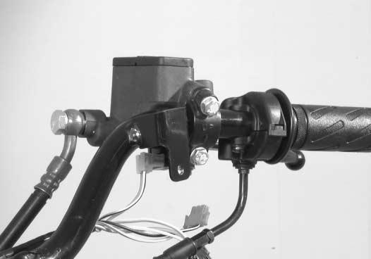
19 PERIODIC MAINTENANCE 2-7 CARBURETOR Inspect Initially at km (2 months) and every km (6 months) thereafter. ENGINE IDLE SPEED Adjust the throttle cable play. Remove the left side leg shield. ( 5-3) Warm up the engine. NOTE: Make this adjustment when the engine is hot. 1 Connect the multi circuit tester to the high-tension cord. Start the engine, and then turn the throttle stop screw 1 to set the engine idle speed as shown below. Engine idle speed: ± 200 r/min : Multi circuit tester set THROTTLE CABLE PLAY Throttle cable play A should be 2 4 mm as measured at the throttle grip when turning the throttle grip lightly. If the throttle cable play A is incorrect, adjust it as follows: Loosen the locknut 1 and turn the adjuster 2 in or out until the specified play is obtained. Tighten the locknut 1 while holding the adjuster 2. Throttle cable play A: 2 4 mm 2 1 After the adjustment is completed, check that handlebar movement does not raise the engine idle speed and that the throttle grip returns smoothly and automatically. FUEL LINE Inspect initially at km (2 months) and every km (6 months) thereafter. Replace every four years.


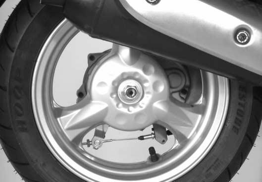
20 2-8 PERIODIC MAINTENANCE FINAL GEAR OIL Inspect initially at km (2 months) and every km (12 months) thereafter. 1 Remove the final gear oil level bolt 1 and inspect the oil level. If the oil level is below the brim of the final gear oil level hole, add oil until it runs out from the level hole. Final gear oil viscosity and classification: SAE 10W-40 Tighten the final gear oil level bolt 1 to the specified torque. Final gear oil level bolt: 12 N m (1.2 kgf-m) BRAKES Inspect initially at km (2 months) and every km (6 months) thereafter. REAR BRAKE LEVER PLAY Turn the adjusting nut 1 until the rear brake lever play A is within specification. Rear brake lever play A: mm REAR BRAKE SHOE WEAR This motorcycle is equipped with a brake lining wear limit indicator 1 on the brake cam lever. To check brake lining wear, perform the following steps. Make sure that the rear brake lever play is properly adjusted. Squeeze the rear brake lever. Make sure that the indicator 1 is within the range A embossed on the crankcase. If the indicator goes beyond the range, the brake shoe assembly should be replaced with a new set of shoes. ( 5-30) FRONT BRAKE PADS ( 5-11) 1 1 A A
. Replace fluid every two years.")

21 PERIODIC MAINTENANCE 2-9 BRAKE HOSE Inspect every km (6 months). Replace every four years. Check the brake hose for leakage, cracks, wear, and damages. If any damages are found, replace the brake hose with a new one. BRAKE FLUID Inspect every km (6 months). Replace fluid every two years. FRONT BRAKE FLUID LEVEL Keep the motorcycle upright and place the handlebars straight. Check the brake fluid level by observing the lower limit line on the brake fluid reservoir. When the brake fluid level is below the lower limit line, replenish with a brake fluid that meets the following specification. NOTE: If the brake fluid level is difficult to check, remove the master cylinder reservoir cap to check the brake fluid level. Specification and classification: DOT 4 The brake system is filled with an glycol-based brake fluid, which is classified DOT 4. Do not use or mix other types of brake fluid, such as silicone-based and petroleum-based brake fluids when refilling the brake system, otherwise serious damage to the brake system will result. Do not use any brake fluid taken from old, used, or unsealed containers. Do not reuse brake fluid left over from the last servicing or which has been stored for a long period of time. When storing brake fluid, be sure to seal the container completely and keep it out of the reach of children. When replenishing brake fluid, be sure not to get any dust or other foreign materials in the fluid. Brake fluid, if it leaks, will interfere with safe running and immediately discolor painted surfaces. Check the brake hoses and hose joints for cracks and oil leakage before riding.
22 2-10 PERIODIC MAINTENANCE AIR BLEEDING THE BRAKE FLUID CIRCUIT Air trapped in the brake fluid circuit acts like a cushion to absorb a large proportion of the pressure developed by the master cylinder, thus interferes with the full braking performance of the brake caliper. The presence of air is indicated by sponginess of the brake lever and also by lack of braking force. Considering the danger to which such trapped air exposes the machine and rider, it is essential that, after remounting the brake and restoring the brake system to the normal condition, the brake fluid circuit be purged of air in the following manner: Fill the master cylinder reservoir to the upper end of the inspection window. Replace the reservoir cap to prevent dirt from entering. Attach a hose to the caliper bleeder valve, and insert the free end of the hose into a receptacle. Bleed air from the bleeder valve. Squeeze and release the brake lever several times in rapid succession and squeeze the lever fully without releasing it. Loosen the bleeder valve by turning it a quarter of a turn so that the brake fluid runs into the receptacle; this will remove the tension of the brake lever causing it to touch the handlebar grip. Then, close the valve, pump and squeeze the lever, and open the valve. Repeat this process until the fluid flowing into the receptacle no longer contains air bubbles. NOTE: While bleeding the brake system, replenish the brake fluid in the reservoir as necessary. Make sure that there is always some fluid visible in the reservoir. Close the bleeder valve, and disconnect the hose. Fill the reservoir with brake fluid to the top of the inspection window. Air bleeder valve: 7.5 N m (0.75 kgf-m) Handle the brake fluid with care: the fluid reacts chemically with paint, plastics, rubber materials, etc.
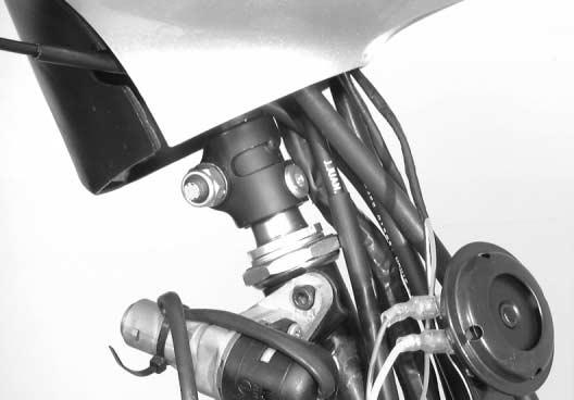
23 PERIODIC MAINTENANCE 2-11 STEERING Inspect Initially at km (2 months) and every km (6 months) thereafter. The steering should be adjusted properly for smooth turning of the handlebar and safe operation. Overtight steering prevents smooth turning of the handlebar and too loose steering will cause poor stability. Check that there is no play in the front fork. Support the motorcycle so that the front wheel is off the ground. With the wheel facing straight ahead, grasp the lower fork tubes near the axle and pull forward. If play is found, adjust the steering. ( 5-28 and 5-29) FRONT FORK Inspect every km (12 months). Inspect the front fork for scoring or scratches on the outer surface of the inner tubes. If any damages are found, replace the inner tubes with new ones. ( 5-18 and 5-19) REAR SUSPENSION Inspect every km (12 months). Inspect the rear shock absorber for oil leakage and the bushings for wear and damage. If oil leakage or any damages are found, replace the rear shock absorber with a new one.
24 2-12 PERIODIC MAINTENANCE TIRES Inspect initially at km (2 months) and every km (6 months) thereafter. TIRE TREAD CONDITION Operating the motorcycle with excessively worn tires will decrease riding stability and consequently invite a dangerous situation. It is highly recommended to replace a tire when the remaining depth of the tire tread reaches the following specification. Tire tread depth (front and rear) Service Limit: 1.6 mm : Tire depth gauge TIRE PRESSURE If the tire pressure is too high or too low, steering will be adversely affected and tire wear will increase. Therefore, maintain the correct tire pressure for good roadability and a longer tire life. Cold inflation tire pressure is as follows. Cold inflation tire pressure Solo riding Front: 125 kpa (1.25 kgf/cm 2 ) Rear: 175 kpa (1.75 kgf/cm 2 ) Dual riding (except for UF50Z) Front: 125 kpa (1.25 kgf/cm 2 ) Rear: 230 kpa (2.30 kgf/cm 2 ) The standard tire fitted on this motorcycle is 120/ L for the front and 130/ L for the rear. The use of tires other than those specified may cause instability. It is highly recommended to use the specified tires.

 Exhaust pipe nut and bolt: 10 N m (1.")

25 PERIODIC MAINTENANCE 2-13 CYLINDER HEAD NUTS AND EXHAUST PIPE NUT AND BOLT Tighten initially at km (2 months) and every km (6 months) thereafter. Cylinder head nuts, when they are not tightened to the specified torque, may result in leakage of the compressed mixture and reduce output. Tighten the cylinder head nuts as follows. Disconnect the spark plug cap and remove the spark plug. ( 2-5) Remove the frame cover. ( 5-4 and 5-5) Remove the cylinder/cylinder head cover 1. Disconnect the spark plug cap. Tighten the cylinder head nuts 2 and exhaust pipe nut 3 and bolt 4 to the specified torque Cylinder head nut: 10 N m (1.0 kgf-m) Exhaust pipe nut and bolt: 10 N m (1.0 kgf-m) 3 4 CHASSIS NUTS AND BOLTS Tighten initially km (2 months) and every km (6 months) thereafter. Check that all chassis nuts and bolts are tightened to their specified torque. Item N m kgf-m 1 Front axle nut Steering stem locknut Handlebar set bolt Handlebar clamp nut Front brake caliper mounting bolt Front brake hose union bolt Front brake caliper air bleeder valve Front brake disc mounting bolt Front brake master cylinder clamp bolt Rear axle nut A Rear shock absorber upper mounting bolt B Rear shock absorber lower mounting nut C Rear brake cam lever nut


26 2-14 PERIODIC MAINTENANCE A 0 B C

27 PERIODIC MAINTENANCE 2-15 GENERAL LUBRICATION Proper lubrication is important for smooth operation and long life of each working part of the motorcycle. Major lubrication points are indicated below Rear brake lever holder 2 Center stand pivot and spring hook 3 Front brake lever holder 4 Speedometer cable NOTE: Before lubricating each part, remove any rust and wipe off any grease, oil, dirt, or grime. Lubricate exposed parts which are subject to rust, with a rust preventative spray, especially whenever the motorcycle has been operated under wet or rainy conditions.
28 2-16 PERIODIC MAINTENANCE AUTOMATIC CLUTCH INSPECTION The UF50/UF50Z is equipped with a centrifugal type automatic clutch and a variable ratio belt drive transmission. To insure proper performance and longevity of the clutch assembly it is essential that the clutch assembly engages smoothly and gradually. Two inspection checks must be performed to thoroughly check the operation of the drive train. Follow the procedures listed. NOTE: Warm up the engine. INITIAL ENGAGEMENT Remove the trunk. ( 5-4) Connect the multi circuit tester to the high-tension cord. Start the engine. While seated on the machine, slowly increase the engine speed and record the speed when the machine begins to move forward : Multi circuit tester Engagement speed: r/min If the engagement speed does not coincide with the standard range, refer to the following section to inspection the respective items for any abnormalities. CLUTCH SHOE/MOVABLE DRIVEN FACE to 3-22
29 PERIODIC MAINTENANCE 2-17 CLUTCH LOCK-UP Perform this inspection to determine if the clutch is engaging fully and not slipping. Remove the trunk. ( 5-4) Connect the multi circuit tester to the high-tension cord. Start the engine. Apply the rear brake as firm as possible. Fully open the throttle for a brief period and note the maximum engine speed sustained during the test cycle : Multi circuit tester Lock-up speed: r/min Do not apply full power for more than 10 seconds or damage to the clutch assembly or engine may occur. If the lock-up speed does not coincide with the standard range, refer to the following section to inspect the respective items for any abnormalities. CLUTCH SHOE/MOVABLE DRIVEN FACE to 3-22
30 ENGINE 3-1 ENGINE CONTENTS ENGINE COMPONENTS REMOVABLE WITH THE ENGINE IN PLACE ENGINE REMOVAL AND REMOUNTING ENGINE REMOVAL ENGINE REMOUNTING ENGINE DISASSEMBLY ENGINE COMPONENTS INSPECTION AND SERVICE CYLINDER HEAD DISTORTION CYLINDER PISTON CRANKSHAFT AND CONROD REED VALVE CLUTCH SHOE/MOVABLE DRIVEN FACE MOVABLE DRIVE FACE KICK STARTER BEARINGS OIL SEALS ENGINE MOUNTING BUSHINGS ENGINE REASSEMBLY CRANKSHAFT CRANKCASE REAR AXLE SHAFT AND TRANSMISSION GENERATOR STARTER PINION AND STARTER GEAR DRIVE BELT PISTON CYLINDER CYLINDER HEAD OIL PUMP GEAR INTAKE PIPE EXHAUST PIPE/MUFFLER
31 3-2 ENGINE ENGINE COMPONENTS REMOVABLE WITH THE ENGINE IN PLACE The parts listed below can be removed and reinstalled without removing the engine from the frame. Refer to the page listed in each section for removal reinstallation instructions. ENGINE LEFT SIDE PARTS REMOVAL INSTALLATION Air cleaner 3-6 Kick starter lever Clutch cover Kick starter Fixed drive face 3-9 Movable drive face Clutch housing Clutch shoe assembly 3-9 Drive belt Starter driven gear Starter pinion gear ENGINE RIGHT SIDE PARTS REMOVAL INSTALLATION Exhaust pipe/muffler assembly Cooling fan 3-7 Starter motor 3-8 Generator rotor Stator coil Pickup coil Gearbox cover Final driven gear ENGINE CENTER PARTS REMOVAL INSTALLATION Oil pump 3-6 Oil pump gear Intake pipe Reed valve 3-7 Cylinder head Cylinder Piston


 Disconnect the fuel hose 1, vacuum hose 2, oil hose 3, and carburetor")

32 ENGINE 3-3 ENGINE REMOVAL AND REMOUNTING ENGINE REMOVAL Before taking the engine out of the frame, wash the engine with a steam cleaner. Engine removal is sequentially explained in the following steps. Remove the side leg shields and frame covers. ( 5-3 to 5-5) Disconnect the - battery lead wire. ( 6-30) Disconnect the fuel hose 1, vacuum hose 2, oil hose 3, and carburetor heater lead wire 4. Remove the carburetor top cap 5 with the throttle cable and throttle valve Disconnect the spark plug cap. Disconnect the engine ground wire. Disconnect the thermoelement coupler 6, starter motor coupler 7, and generator coupler


33 3-4 ENGINE Remove the rear brake cable holders 1 and adjusting nut Disconnect the air cleaner intake boot. Remove the rear shock absorber lower mounting bolt. Remove the engine mounting nut, shaft, and engine.
34 ENGINE 3-5 ENGINE REMOUNTING Remount the engine in the reverse order of removal. Pay attention to the following points: Install the crankcase bracket 1 to the frame and insert the crankcase bracket mounting shaft. Push down on the rear part of the crankcase bracket and have the damper 2 touch the stopper 3. While holding the damper, tighten the engine mounting bracket nut 4 to the specified torque. Engine mounting bracket nut: 65 N m (6.5 kgf-m) Install the engine and tighten the engine mounting nut 5 to the specified torque. Engine mounting nut: 60 N m (6.0 kgf-m) NOTE: When tightening the engine mounting nut, make sure that the front wheel is elevated. Tighten the rear shock absorber lower mounting nut 6 to the specified torque. Rear shock absorber nut: 35 N m (3.5 kgf-m) Place 65 kg on the seat, after installing the engine. Check that clearances A and B are equal. If clearances A and B are not equal, repeat the engine installation procedures. After installing the engine, properly route the wire harness, cables, and hoses. Refer to the wire and cable routing sections. ( 7-10 to 7-16) Refer to the following sections to adjust the respective items to specification. THROTTLE CABLE PLAY ENGINE IDLE SPEED REAR BRAKE CABLE ADJUSTMENT OIL PUMP AIR BLEEDING


35 3-6 ENGINE ENGINE DISASSEMBLY Remove the air cleaner. Remove the exhaust pipe/muffler assembly. Disconnect the oil hoses and remove the oil pump.


36 ENGINE 3-7 Remove the oil pump gear 1, intake pipe and carburetor. A: Twist-off bolt 1 A Remove the reed valve and gaskets. Remove the cylinder/cylinder head cover 2 and cooling fan cover Remove the cooling fan. Remove the cooling fan case.


37 3-8 ENGINE Remove the rear fender. Loosen the cylinder head nuts diagonally, as shown, and then remove them. Remove the cylinder head and gasket. Remove the cylinder and gasket. Place a clean rag over the cylinder base to prevent the piston pin circlip from dropping into the crankcase. Then, remove the piston pin circlip with long-nose pliers. Remove the piston pin and piston. Remove the starter motor.


38 ENGINE 3-9 Remove the kick starter lever 1, clutch cover 2, gaskets, and dowel pins. 2 1 Hold the generator rotor using the special tool and then remove the kick starter nut : Rotor holder Remove the kick starter 3, fixed drive face 4, movable drive face 5, spacers, and washers Hold the clutch housing using the special tool and then remove the clutch housing nut : Rotor holder Remove the clutch housing, clutch shoe assembly, and drive belt. Remove the starter driven gear.


39 3-10 ENGINE Remove the starter pinion gear cap 1, starter pinion gear assembly 2, and dowel pins. Drain the final gear oil. Hold the generator rotor using the special tool and then remove the generator rotor nut : Rotor holder Remove the generator rotor using the special tool : Crankcase separating tool Remove the stator coil 3, pickup coil 4, and key


40 ENGINE 3-11 Remove the rear wheel. Remove the brake shoes. Remove the brake cam lever 1, return spring 2, brake lining wear limit indicator 3, and brake camshaft Remove the gearbox cover. Remove the final driven gear with the rear axle shaft 5, idle shaft/gear 6, and dowel pins


41 3-12 ENGINE Remove the driveshaft using the special tool : Crankcase separating tool Remove the center stand spring 1. Remove the cotter pin 2 and center stand shaft 3. Remove the center stand 4. Remove the crankcase bolts. Separate the left and right crankcases using the special tool : Crankcase separating tool Remove the gaskets and dowel pins. Replace the removed gaskets with new ones. Remove the crankshaft using the special tool : Crankcase separating tool
42 ENGINE 3-13 ENGINE COMPONENTS INSPECTION AND SERVICE CYLINDER HEAD DISTORTION Decarbonize the combustion chamber. Check the gasket surface of the cylinder head for distortion. Use a straightedge and thickness gauge. Take clearance readings at several places. If readings exceed the service limit, replace or flatten the cylinder head : Thickness gauge Cylinder head distortion Service Limit: 0.05 mm Place a sheet of emery paper (about #400 grit) on a surface plate. Use a figure-eight motion when grinding the cylinder head surface. The gasket surface must be smooth and perfectly flat, for a tight fit. A leaky joint can cause reduced power and increased fuel consumption. CYLINDER Remove carbon from the exhaust port and the upper part of the cylinder. Take care not to damage the surface of the cylinder wall. CYLINDER BORE Measure the cylinder bore with the cylinder gauge at 20 mm from the top of the cylinder. If the measurement exceeds the service limit, rebore the cylinder and replace the piston with an oversized piston or replace the cylinder with a new one. Oversized pistons are available in two sizes: 0.5 mm and 1.0 mm : Cylinder gauge set Cylinder bore Service Limit: mm Chamfer the port edges after reboring. Use a scraper and take care not to nick the surface of the walls. Use emery paper (about #400 grit) to smooth the chamfered edges. NOTE: Shallow grooves or minor scuffs can be removed by using emery paper (about #400 grit). If the flaws are deep grooves or cannot be removed with the emery paper, the cylinder must be rebored to the next oversize mm mm mm
43 3-14 ENGINE PISTON PISTON DIAMETER Measure the piston diameter using a micrometer at 15 mm from the skirt end. If the piston diameter is less than the service limit, replace the piston with a new one : Micrometer (25 50 mm) Piston diameter Service Limit: mm PISTON-TO-CYLINDER CLEARANCE Subtract the piston diameter from the cylinder bore diameter. If the piston-to-cylinder clearance exceeds the service limit, rebore the cylinder and use an oversized piston or replace both the cylinder and the piston with new ones. Piston-to-cylinder clearance Service Limit: mm CARBON REMOVAL Remove carbon from the crown of the piston and piston ring grooves. After cleaning the piston ring grooves, install the piston rings and rotate them in their respective grooves to be sure that they move smoothly. Carbon in the piston ring groove can cause the piston ring to get stuck, reducing engine power output. If any scuffing is found, replace the piston with a new one. Shallow grooves or minor scuffs can be removed by using emery paper (about #400 grit) as shown.
44 ENGINE 3-15 PISTON PIN AND PIN BORE Measure the piston pin bore inside diameter using the dial calipers and the piston pin outside diameter using the micrometer. If either is out of specification or the difference between the measurements is more than their limits, replace the piston and piston pin with new ones : Dial calipers : Micrometer (0 25 mm) Piston pin bore I.D. Service Limit: mm Piston pin O.D. Service Limit: mm PISTON RING FREE END GAP AND PISTON RING END GAP Measure the piston ring free end gap using vernier calipers. Then, fit the piston ring squarely into the cylinder and measure the piston ring end gap using a thickness gauge. If any of the measurements exceed the service limit, replace the piston ring with a new one : Vernier calipers Piston ring free end gap Service Limit: 1st: 3.2 mm... R 2nd: 3.4 mm... R : Thickness gauge Piston ring end gap Service Limit: 0.80 mm Measure the piston-ring-to-groove clearance using the thickness gauge. If any of the clearances are out of specification, clean the groove of the piston and piston rings : Thickness gauge Piston-ring-to-groove clearance Standard: 1st: mm 2nd: mm
45 3-16 ENGINE CRANKSHAFT AND CONROD 1 Oil seal (R) 2 Bearing (R) 3 Crankshaft (R) 4 Crank pin 5 Crank pin bearing 6 Conrod 7 Crankshaft (L) 8 Spacer 9 Piston pin bearing 0 Bearing (L) A Oil seal (L) B Oil seal CRANKSHAFT RUNOUT Support the crankshaft using V-blocks as shown. Position the dial gauge, as shown, and rotate the crankshaft slowly to read the runout. If the runout exceeds the service limit, correct the runout or replace the crankshaft assembly with a new one : Magnetic stand : Dial gauge (1/100 mm) : V-block set (100 mm) Crankshaft runout Service Limit: 0.05 mm


46 ENGINE 3-17 CONROD DEFLECTION Wear on the big end of the conrod can be estimated by checking the movement of the small end of the rod. This method can also check the extent of wear on the parts of the big end of the conrod : Magnetic stand : Dial gauge (1/100 mm) : V-block set (100 mm) Conrod deflection Service Limit: 3.0 mm If the service limit is exceeded, replace the crankshaft assembly or bring the deflection into specification by replacing the worn parts (e.g., conrod, big end bearing and crank pin). CONROD SMALL END I.D. Measure the conrod small end inside diameter using the dial calipers. If the conrod small end inside diameter exceeds the service limit, replace the conrod with a new one. Conrod small end I.D. Service Limit: mm : Dial calipers REASSEMBLY When rebuilding the crankshaft, the width between the webs should be within the standard range. Crank web to web width Standard: 36.0 ± 0.05 mm REED VALVE Inspect the reed valve for wear or damage. If any damages are found, replace the reed valve with a new one.


47 3-18 ENGINE CLUTCH SHOE/MOVABLE DRIVEN FACE 1 Fixed driven face 2 Bearing 3 Circlip 4 Needle roller bearing 5 Movable driven face 6 Oil seal 7 Pin 8 O-ring 9 Movable driven face spring guide 0 Oil seal A Spring B Clutch shoe assembly C Clutch housing D Washer A Clutch shoe nut B Clutch housing nut ITEM N m kgf-m A B DISASSEMBLY If the engine speed does not coincide with the specified engine speed range, disassemble the clutch shoe/movable driven face as follows. Hold the clutch shoe assembly using the special tools and then loosen the clutch shoe nut : Rotor holder : Rotor holder attachment Remove the clutch shoe nut 1 while holding down the clutch shoe assembly, as shown. Gradually ease apart the clutch shoe assembly (to counter the clutch spring force). Quickly releasing the clutch shoe assembly may cause the parts to fly apart.
48 ENGINE 3-19 Remove the clutch shoe assembly 1 and driven face spring 2. Use a thin-blade screwdriver to pry up the movable driven face spring guide. Remove the pins 3, movable driven face 4, and fixed driven face 5. Remove the bearing using the special tools : Bearing remover : Sliding hammer Replace the removed bearing with a new one. Remove the circlip.
49 3-20 ENGINE Remove the bearing using the special tool : Bearing remover Replace the removed bearing with a new one. Remove the oil seals 1 and O-rings 2. Replace the removed oil seals and O-rings with new ones. CLUTCH SHOE Inspect the clutch shoe for chips, cracks, uneven wear and burning. Check the thickness of the shoe using vernier calipers. If any damages are found or if the thickness is less than the service limit, replace the clutch shoe with a new one : Vernier calipers Clutch shoe thickness Service Limit: 2.0 mm Inspect the clutch spring for stretched or broken coils. If any damages are found, replace the clutch spring with a new one. Replace the clutch shoe and clutch spring as a set. Inspect the clutch housing surface for scrolling, cracks, or uneven wear and measure the inside diameter of the clutch housing with inside calipers. Measure the diameter at several points to check for out-of-round and wear. If any damages are found or if the inside diameter exceeds the service limit, replace the clutch housing with a new one. Clutch housing I.D. Service Limit: mm
50 ENGINE 3-21 DRIVEN FACE SPRING Measure the free length of the driven face spring. If the length is shorter than the service limit, replace the spring with a new one. Driven face spring length Service Limit: mm DRIVEN FACE PINS AND OIL SEALS Rotate the driven faces and make sure that they turn smoothly. If they stick or do not turn smoothly, inspect the lip of each oil seal, and the sliding surface and sliding pins for wear or damage. If any damages are found, replace the driven face with a new one. DRIVEN FACE Inspect the drive belt contacting surface of both driven faces for any scratches, wear or damage. If any damages are found, replace the driven faces with new ones. REASSEMBLY Reassemble the clutch shoe assembly and movable driven face in the reverse order of disassembly. Pay attention to the following points. Install the bearing 2 in the fixed driven face 1 using the special tool : Bearing installer Securely install the circlip.


51 3-22 ENGINE Install the needle roller bearing using the special tool : Bearing installer NOTE: Face the stamped side of the needle roller bearing out. Apply SUZUKI SUPER GREASE A between the sliding surface of the fixed driven face and movable driven face : SUZUKI SUPER GREASE A NOTE: When installing the movable face to the fixed face, make sure that the oil seal is positioned properly. Install the pins 1 at three places on the drive face hub. Apply sufficient SUZUKI SUPER GREASE A to the cam where the pins are placed and to the surface of the driven face, as shown : SUZUKI SUPER GREASE A Position the two O-rings 2. Install the movable driven face spring guide. NOTE: Remove any grease from the movable driven face spring guide, after installation. Hold the clutch shoe assembly using the special tools and then tighten the clutch shoe nut to the specified torque : Rotor holder : Rotor holder attachment Clutch shoe nut: 50 N m (5.0 kgf-m)


52 ENGINE 3-23 MOVABLE DRIVE FACE 1 Movable drive face 2 Roller 3 Movable drive plate 4 Damper 5 Movable drive face cover 6 Spacer 7 Spacer 8 Drive belt 9 Fixed drive face 0 Washer A Kick starter B Concave washer A Kick starter nut ITEM N m kgf-m A DISASSEMBLY Remove the movable drive face cover 1 and movable drive plate DRIVE FACE Inspect the belt contact surface of the drive faces for wear, scratches or any abnormalities. If any damages are found, replace the drive face with a new one.
53 3-24 ENGINE ROLLER AND SLIDING SURFACE Inspect each roller and its sliding surface for wear or damage. If any damages are found, replace the rollers as a set. DRIVE BELT Remove the drive belt and check for cracks, wear and separation and measure the drive belt width with vernier calipers. If any damages are found or if the width of the drive belt is less than the service limit, replace the drive belt with a new one. Drive belt width Service Limit: 17.4 mm Always keep the drive belt away from grease, oil, etc. REASSEMBLY Mount the three dampers 1 on the movable drive plate 2 and install it onto the movable drive face. Install the movable drive face cover 3. NOTE: Make sure that the movable drive plate is fully positioned inside the movable drive face, otherwise the rollers may fall out. Insert the spacer 4.


54 ENGINE 3-25 KICK STARTER 1 Spacer 2 Kick starter shaft 3 Kick starter spring 4 Clutch cover 5 Dowel pin 6 Gasket 7 Gasket 8 Kick starter lever 9 Kick starter drive gear DISASSEMBLY Remove the kick starter driven gear 1, kick starter shaft spring 2, and kick starter shaft REASSEMBLY Apply SUZUKI SUPER GREASE A onto the inside of the kick starter shaft spacer : SUZUKI SUPER GREASE A


55 3-26 ENGINE Apply a light coat of SUZUKI SUPER GREASE A onto the end of the kick starter shaft : SUZUKI SUPER GREASE A Install the kick starter spring and hook its end 1 onto the clutch cover boss Apply SUZUKI SUPER GREASE A onto the shaft and gear of the kick starter drive gear : SUZUKI SUPER GREASE A Install the kick starter drive gear. BEARINGS Play Wash the bearing with a cleaning solvent and lubricate it with motor oil before inspection. Rotate the inner race and check to see that it turns smoothly. If it does not turn quietly and smoothly, or if there are signs of any abnormalities, the bearing is defective and must be replaced with a new one. Play REAR AXLE SHAFT BEARING Remove the bearing retainer. Remove the rear axle shaft bearing using the special tool : Bearing remover set Replace the removed bearing with a new one.


56 ENGINE 3-27 Install the rear axle shaft bearing using the special tool : Bearing installer set RIGHT DRIVESHAFT BEARING AND IDLE SHAFT BEARING Remove the right driveshaft bearing and idle shaft bearing using the special tools : Bearing remover : Sliding hammer Replace the removed bearings with new ones. Install the right driveshaft bearing and idle shaft bearing using the special tool : Bearing installer set LEFT DRIVESHAFT BEARING Remove the left driveshaft bearing using the special tool : Bearing remover set Replace the removed bearing with a new one. Install the left driveshaft bearing using the special tool : Bearing installer set


57 3-28 ENGINE RIGHT CRANKSHAFT BEARING Remove the right crankshaft bearings using the special tools : Bearing remover : Sliding hammer Replace the removed bearing with a new one. Install the right crankshaft bearing using the special tool : Bearing installer set LEFT CRANKSHAFT BEARING Remove the left crankshaft bearing using the special tools : Bearing remover : Sliding hammer Replace the removed bearing with a new one. Install the left crankshaft bearing using the special tool : Bearing installer set OIL SEALS Damage to the lip of the oil seal may result in leakage of the airfuel mixture or gear oil. Inspect the oil seal and if it is damaged, replace it with a new one.


58 ENGINE 3-29 Install the oil seals into the crankcase and gearbox cover, as shown below. Replace the removed oil seals with new ones. Apply SUZUKI SUPER GREASE A to the lip of the oil seals : SUZUKI SUPER GREASE A Be sure to apply THREAD LOCK 1342 to the outer surfaces of the right and left crankshaft oil seals to prevent them from moving : THREAD LOCK 1342 REAR AXLE SHAFT OIL SEAL Remove the rear axle shaft bearing. ( 3-26) Remove the rear axle shaft oil seal from the gearbox cover using the special tool : Oil seal remover Replace the removed oil seal with a new one. Install the rear axle shaft oil seal into the gearbox cover, slowly, using the special tool : Bearing installer set DRIVE SHAFT OIL SEAL Remove the drive shaft oil seal from the left crankcase using the special tool : Oil seal remover Replace the removed oil seal with a new one.


59 3-30 ENGINE Install the drive shaft oil seal into the left crankcase, slowly, using the special tool : Bearing installer set CRANKSHAFT OIL SEALS Remove the crankshaft oil seals from the left and right crankcase, using the special tool : Oil seal remover Replace the removed oil seals with new ones. Install the crankshaft oil seal into the right crankcase, slowly, using the special tool : Bearing installer set NOTE: Align the oil seal with the edge A of the crankcase, as shown. Install the left crankshaft oil seals using the special tool after installing the crankshaft to the crankcase. ( 3-33)
60 ENGINE 3-31 ENGINE MOUNTING BUSHINGS Inspect each engine mounting bushings 1 and 2 for damage. If any damage is found, replace the engine mounting bushing with a new one. Press out the engine mounting bushings in a vise using two steel tubes of the appropriate size, as shown. Replace the removed bushing with a new one. Crankcase Crankcase Front side Rear side Install the engine mounting bushings using two steel tubes of the appropriate size and a vise. Press the mounting bushings 1 and 2 into the crankcase holes, as shown. NOTE: The knurled end 3 should face in. Projections A and B should be aligned evenly. Crankcase 0.5 mm 0.5 mm Crankcase 0.5 mm 0.5 mm


61 3-32 ENGINE ENGINE REASSEMBLY Reassemble the engine in the reverse order of disassembly. The following steps require special attention or precautionary measures should be taken. NOTE: Apply engine oil to each running and sliding part before reassembling. CRANKSHAFT Mount the crankshaft into the right crankcase by pulling its right end into the crankcase using the special tools : Crankshaft installer : Conrod holder Never fit the crankshaft into the crankcase by striking it with a plastic hammer. Always use the special tool, otherwise the crankshaft may be misaligned. CRANKCASE Install the two dowel pins 1 and new gaskets 2. Install the left crankcase onto the right crankcase Tighten the crankcase bolts. NOTE: After the crankcase bolts have been tightened, make sure that the crankshaft rotates smoothly. If the crankshaft does not rotate smoothly, try to free it by tapping it with a plastic hammer.
62 ENGINE 3-33 Install the left crankshaft inner oil seal 1 using the special tool : Bearing installer 28.5 mm Apply SUZUKI SUPER GREASE A (approximately 10 g) to the oil pump drive gear (on the crankshaft surface side) : SUZUKI SUPER GREASE A Install the left crankshaft outer oil seal using the special tool : Bearing installer set


63 3-34 ENGINE REAR AXLE SHAFT AND TRANSMISSION 1 Crankcase 2 Gearbox cover 3 Rear axle shaft/final driven gear 4 Idle shaft/gear 5 Washer 6 Washer 7 Drive shaft Install the idle shaft/gear 1, with the thrust washer 2, into the gearbox. Install the rear axle shaft/final driven gear 3. Install the thrust washer 4 and the O-ring


64 ENGINE 3-35 Install the driveshaft 1 and dowel pins Install the gearbox cover. Tighten the bolts, a little at a time, diagonally. Apply a light coat of SUZUKI SUPER GREASE A onto the pivoting surface of the brake cam, and then install the brake cam into the crankcase : SUZUKI SUPER GREASE A Position the brake cam so that the punch mark A faces the rear axle shaft. A


 Install the brake shoes and rear wheel.")
 to the axle nut before")
 GENERATOR Remove any grease from the tapered")
65 3-36 ENGINE Align the tang 1 on the brake lining wear indicator plate 2 with the cutaway 3 on the brake cam. Then, slide the brake lining wear indicator plate onto the brake cam. Install the return spring and brake cam lever onto the brake cam and tighten the brake cam lever nut to the specified torque. Brake cam lever nut: 10 N m (1.0 kgf-m) Install the brake shoes and rear wheel. Tighten the rear axle nut to the specified torque. NOTE: Apply final gear oil (10W-40) to the axle nut before tightening it. Rear axle nut: 120 N m (12.0 kgf-m) GENERATOR Remove any grease from the tapered portion of the crankshaft and also from the generator rotor. Install the key 1, stator coil 2, and pickup coil

 STARTER PINION AND STARTER GEAR Tighten the final gear oil drain bolt 1 to the")
 Add final gear oil until it flows from the final gear oil level hole 2.")


66 ENGINE 3-37 Apply THREAD LOCK SUPER 1322 to the generator rotor nut and then tighten it to the specified torque using the special tool : THREAD LOCK SUPER : Rotor holder Generator rotor nut: 40 N m (4.0 kgf-m) STARTER PINION AND STARTER GEAR Tighten the final gear oil drain bolt 1 to the specified torque. 2 Final gear oil drain bolt: 5.5 N m (0.55 kgf-m) Add final gear oil until it flows from the final gear oil level hole 2. Final gear oil quantity: 130 ml 1 Tighten the final gear oil level bolt to the specified torque. Oil level bolt: 12 N m (1.2 kgf-m) Apply SUZUKI SUPER GREASE A onto the starter pinion shaft and install the starter pinion gear assembly : SUZUKI SUPER GREASE A Insert the dowel pins 4. Install the starter idle gear cap 5. Install the starter driven gear 6 onto the left crankshaft. NOTE: The convex side of the starter driven gear should face out.


67 3-38 ENGINE DRIVE BELT Insert the drive belt, as low as possible, between the clutch shoe/movable driven face while pulling out the driven face to provide the maximum drive belt clearance. The drive belt contact surface of the driven face should be thoroughly cleaned. Thoroughly clean the clutch housing and position it over the clutch shoe assembly. Hold the clutch housing using the special tool, and tighten the clutch housing nut to the specified torque : Rotor holder Clutch housing nut: 50 N m (5,0 kgf-m) Install the movable drive face onto the crankshaft, as shown. NOTE: Thoroughly clean the drive belt contact surface. Hold the generator rotor using the special tool, and tighten the kick starter nut to the specified torque : Rotor holder Kick starter nut: 50 N m (5.0 kgf-m) Turn the fixed drive face by hand, until the drive belt is properly seated and both the drive and driven faces rotate together smoothly and without slipping.


68 ENGINE 3-39 Install the dowel pins 1 and new gaskets Install the clutch cover 3 and kick starter lever PISTON Install the piston rings onto the piston. 1st: Keystone ring 2nd: Rectangular ring and expander ring NOTE: The piston rings should be installed with the mark facing up. Position the piston ring gaps, as shown. Before inserting the piston into the cylinder, check that the gaps are properly positioned. CORRECT INCORRECT Securely install the circlip 1. NOTE: The arrow mark 2 on the piston crown should be pointing towards the exhaust side. Apply engine oil onto the piston pin, and then install the piston.

69 3-40 ENGINE CYLINDER Apply engine oil onto the piston and cylinder wall surfaces, and then install the cylinder over the piston carefully. CYLINDER HEAD Tighten the cylinder head nuts diagonally, as shown, and to the specified torque. Cylinder head nut: 10 N m (1.0 kgf-m) OIL PUMP GEAR Apply SUZUKI SUPER GREASE A onto the oil pump gear, and then install it : SUZUKI SUPER GREASE A INTAKE PIPE Install the intake pipe and tighten the bolts securely. NOTE: Be sure to use the special twist-off bolt A as shown. A EXHAUST PIPE/MUFFLER Tighten the exhaust pipe mounting nut and bolt to the specified torque. Exhaust pipe mounting nut and bolt: 10 N m (1.0 kgf-m)
70 FUEL AND LUBRICATION SYSTEM 4-1 FUEL AND LUBRICATION SYSTEM CONTENTS FUEL VALVE FUEL TANK AND OIL TANK REMOVAL REMOUNTING FUEL TANK CUSHIONS CARBURETOR CONSTRUCTION I. D. NO. LOCATION SPECIFICATIONS REMOVAL DISASSEMBLY CLEANING INSPECTION AND ADJUSTMENT REASSEMBLY REMOUNTING OIL PUMP AIR BLEEDING DISCHARGE RATE CHECK


71 4-2 FUEL AND LUBRICATION SYSTEM FUEL VALVE When the engine has started, negative pressure (vacuum) is generated at the intake port. The negative pressure causes the fuel valve diaphragm to compress its spring, opening the fuel passageway and allowing the fuel to flow to the carburetor. When the engine has stopped, the spring pushes against the valve, closing the fuel passageway, and stopping the flow of fuel to the carburetor. To carburetor Air vent hose Negative pressure From fuel tank


72 FUEL AND LUBRICATION SYSTEM 4-3 FUEL TANK AND OIL TANK REMOVAL Gasoline is highly flammable and explosive. Keep heat, sparks, and flames away from gasoline. Remove the frame cover. ( 5-4 and 5-5) Disconnect the turn signal light lead wires 1 and license plate light coupler Disconnect the fuel level indicator switch coupler. Disconnect the air vent hose 3 and fuel hose Remove the lower fuel tank cover mounting bolts.


73 4-4 FUEL AND LUBRICATION SYSTEM Remove the fuel tank cap 1 and fuel tank 2. NOTE: After removing the fuel tank, reinstall the fuel tank cap. 2 1 Disconnect the oil hose 3, oil level indicator switch coupler 4, and remove the oil tank REMOUNTING Remount the fuel tank and oil tank in the reverse order of removal.
74 FUEL AND LUBRICATION SYSTEM 4-5 FUEL TANK CUSHIONS Cushion 105 mm 8 mm A 80 mm 13 mm 15 mm 40 mm 65 mm 20 mm 25 mm 6 mm 20 mm 15 mm 15 mm VIEW A Cushion mm 75 mm B VIEW B


75 4-6 FUEL AND LUBRICATION SYSTEM CARBURETOR CONSTRUCTION 1 Top cap 2 Throttle valve spring 3 Jet needle 4 Throttle valve 5 Thermoelement 6 Carburetor body 7 Pilot air screw 8 Throttle stop screw 9 Needle valve 0 Float pin A Float B Needle jet C Needle jet holder D Slow jet E Main jet F Float chamber G Thermoswitch A Carburetor heater ITEM N m kgf-m A I. D. NO. LOCATION The carburetor has an I. D. number A stamped on its body according to its specifications. A
76 FUEL AND LUBRICATION SYSTEM 4-7 SPECIFICATIONS ITEM SPECIFICATION Carburetor type KEIHIN PWS14 Bore size 14 mm I.D. No. 30F0 Idle r/min ± 200 r/min Float height 5.1 ± 0.5 mm Main jet (M.J.) # 65 Jet needle (J.N.) N5GJ-2nd Slow jet (S.J.) # 42 Air screw (A.S.) 2 turns back Throttle cable play 2 4 mm


77 4-8 FUEL AND LUBRICATION SYSTEM REMOVAL Remove the trunk. ( 5-4) Remove the clamps, disconnect the thermoelement coupler 1 and carburetor heater lead wire Disconnect the vacuum hose 3 and fuel hose Loosen the carburetor clamp screw and remove the carburetor mounting bolts. Remove the top cap. DISASSEMBLY Remove the throttle cable from the slit in the throttle valve, and then remove the throttle valve 1 along with the jet needle and throttle valve spring


78 FUEL AND LUBRICATION SYSTEM 4-9 Separate the jet needle 1 and throttle valve Remove the each carburetor hoses. Remove the float chamber 3. 3 Remove the float 4 and needle valve 5 by removing the float pin 6. When removing the float pin, be careful not to damage the carburetor body and float Remove the main jet 7, needle jet holder 8, needle jet 9, and pilot jet Remove the throttle stop screw A and pilot air screw B. Do not use wire to clean the passageways, valve seat, and jets. Use compressed air only. B A


79 4-10 FUEL AND LUBRICATION SYSTEM Remove the thermoelement cover 1 and remove the thermoelement Do not disassemble the thermoelement. It is not serviceable. Remove the carburetor heater.
80 FUEL AND LUBRICATION SYSTEM 4-11 CLEANING Some carburetor cleaning chemicals, especially diptype soaking solutions, are very corrosive and must be handled carefully. Always follow the chemical manufacturer s instructions for proper use, handling and storage. Clean all jets with a spray-type carburetor cleaner and dry them using compressed air. Clean all circuits of the carburetor thoroughly not just the perceived problem area. Clean the circuits in the carburetor body with a spray-type cleaner. If necessary, soak each circuit in a dip-type cleaning solution to loosen dirt and varnish. Dry the carburetor body using compressed air. Do not use wire to clean the passageways, valve seat, and jets. If the components cannot be cleaned with a spray-type cleaner it may be necessary to soak them in a dip-type cleaning solution. Always follow the chemical manufacturer s instructions for proper use and cleaning of the carburetor components. After cleaning, reassemble the carburetor with new O-rings. Replace the removed O-rings with new ones. INSPECTION AND ADJUSTMENT Check the following items for any damage or clogging. If any damages are found, replace the damaged parts with new ones. Main jet Throttle valve Pilot jet Float Needle jet Needle valve Pilot air screw Pilot outlet and bypass holes Thermoelement ( 6-21) Carburetor heater ( 6-22) NEEDLE VALVE If foreign matter is caught between the valve seat and the needle valve, the gasoline will continue flowing and overflow. If the valve seat and needle valve are worn beyond the permissible limits, similar trouble will occur. Conversely, if the needle valve sticks, the gasoline will not flow into the float chamber. Clean the float chamber and float parts with gasoline. If the needle valve is worn, as shown in the illustration, replace it with a new valve seat. Clean the fuel passage of the mixing chamber with compressed air. CORRECT INCORRECT


 Adjust the pilot air screw. ( 4-7) Install the throttle valve with the top cap.")

81 4-12 FUEL AND LUBRICATION SYSTEM FLOAT HEIGHT ADJUSTMENT To check the float height, turn the carburetor upside down. Measure the float height A while the float arm is just contacting the needle valve using vernier calipers. Bend the tongue as necessary to bring the float height A to the specified value. Float height A Standard: 5.1 ± 0.5 mm A : Vernier calipers REASSEMBLY Reassemble the carburetor in the reverse order of disassembly. Pay attention to the following points: Tighten the carburetor heater to the specified torque. Carburetor heater: 3 N m (0.3 kgf-m) Adjust the pilot air screw. ( 4-7) Install the throttle valve with the top cap. Align the slit 1 on the throttle valve with the projection 2 on the carburetor body. 1 2 REMOUNTING Remount the carburetor in the reverse order of removal. Pay attention to the following points: After all of the work has been completed, install the carburetor onto the motorcycle and refer to the following section to adjust the respective items to specification. ENGINE IDLE SPEED THROTTLE CABLE PLAY

 Fill the CCI oil gauge with SUZUKI CCI SUPER OIL. Connect the oil gauge to the suction side of the oil pump. Run the engine at 3 000 r/min.")
82 FUEL AND LUBRICATION SYSTEM 4-13 OIL PUMP AIR BLEEDING Whenever air leaks into the oil pipe from the oil tank or the oil pump is removed, the oil pump must be bled of any air. Hold the motorcycle in a stationary position. Loosen the screw 1 to bleed the air. After all of the air has been bled, tighten the screw. 1 DISCHARGE RATE CHECK Use the CCI oil gauge to check the oil pump discharge rate. Measure the amount of oil that the oil pump draws during the procedure. Remove the trunk. ( 5-4) Fill the CCI oil gauge with SUZUKI CCI SUPER OIL. Connect the oil gauge to the suction side of the oil pump. Run the engine at r/min. Keep the engine speed at r/min and allow the pump to draw for five minutes. The measurement on the oil gauge should be within specification : CCI oil gauge Oil discharge amount: ml at r/min for 5 minutes Be sure to place the motorcycle on the center stand. Do not touch the rear wheel while the engine is running. After checking the oil pump, refer to the following section to adjust the respective item to specification. ENGINE IDLE SPEED
83 CHASSIS CHASSIS 5-1 CONTENTS EXTERIOR PARTS CONSTRUCTION REMOVAL REMOUNTING FRONT WHEEL CONSTRUCTION REMOVAL INSPECTION AND DISASSEMBLY REASSEMBLY AND REMOUNTING FRONT BRAKE CONSTRUCTION BRAKE PADS REPLACEMENT BRAKE FLUID REPLACEMENT BRAKE CALIPER REMOVAL AND DISASSEMBLY BRAKE CALIPER INSPECTION BRAKE CALIPER REASSEMBLY AND REMOUNTING BRAKE DISC INSPECTION MASTER CYLINDER REMOVAL AND DISASSEMBLY MASTER CYLINDER INSPECTION MASTER CYLINDER REASSEMBLY AND REMOUNTING FRONT SUSPENSION CONSTRUCTION REMOVAL AND DISASSEMBLY INSPECTION REASSEMBLY AND REMOUNTING HANDLEBAR COVERS AND SPEEDOMETER ASSEMBLY CONSTRUCTION REMOVAL REMOUNTING STEERING STEM CONSTRUCTION REMOVAL AND DISASSEMBLY INSPECTION REASSEMBLY AND REMOUNTING REAR WHEEL, REAR BRAKE, AND REAR SHOCK ABSORBER CONSTRUCTION REMOVAL AND DISASSEMBLY INSPECTION REASSEMBLY AND REMOUNTING TIRES AND WHEELS TIRE REMOVAL INSPECTION INSTALLATION
84 5-2 CHASSIS EXTERIOR PARTS CONSTRUCTION 1 Frame cover (R) 2 Frame cover (L) 3 Trunk 4 Side leg shield (R) 5 Side leg shield (L) 6 Lower leg shield 7 Leg shield 8 Cover 9 Battery holder cover 0 Footboard A Front leg shield

 Remove the side")


85 CHASSIS 5-3 REMOVAL LEG SHIELD Remove the battery. ( 6-30) Remove the side leg shields 1. 1 Remove the frame cover. Remove the footboard 2. 2 Remove the cover 3. 3 Remove the front leg shield mounting screws. Disconnect the headlight lead wires 4 and remove the front leg shield


86 5-4 CHASSIS Remove the lower leg shield 1. 1 Remove the ignition switch cap 2. 2 Remove the leg shield 3. 3 SEAT Remove the seat 1. 1 FRAME COVER Remove the seat. Remove the side leg shield. ( 5-3) Remove the trunk 1 and fuel tank cap


87 CHASSIS 5-5 Remove the upper fuel tank cover 1. After removing the upper fuel tank cover, reinstall the fuel tank cap. 1 Remove the passenger grab handle 2. 2 Remove the frame cover mounting screw. Disconnect the seat lock cable 3, brake light/taillight lead wires 4, and remove the frame cover REMOUNTING Remount the leg shield, seat, and frame cover in the reverse order of removal.


88 5-6 CHASSIS FRONT WHEEL CONSTRUCTION 1 Front axle 2 Spacer 3 Brake disc 4 Bearing 5 Front wheel 6 Spacer 7 Speedometer gearbox A Front axle nut B Brake disc bolt ITEM N m kgf-m A B REMOVAL Disconnect the speedometer cable 1. Remove the front axle nut 2. Raise the front wheel off the ground by raising the motorcycle with a jack or wooden block. Remove the front axle and then the front wheel and spacer. 1 2 Remove the speedometer gearbox.


89 CHASSIS 5-7 Remove the brake disc. INSPECTION AND DISASSEMBLY SPEEDOMETER GEARBOX DUST SEAL Inspect the speedometer gearbox dust seal for damage. If any damage is found, replace the speedometer gearbox with a new one. WHEEL BEARINGS Inspect the play of the wheel bearings by hand while they are in the wheel. Rotate the inner race by hand to inspect for abnormal noise and smooth rotation. If any abnormal noise occurs, or rough movement is noted, replace the wheel bearings with new ones. Remove the wheel bearings as follows: Insert the bearing remover attachment 1 into the wheel bearing. Insert the wedge bar 2 from the opposite side and lock it into the slit of the bearing remover attachment. Drive out the wheel bearing by striking the wedge bar : Bearing remover Play Play Replace the removed bearings with new ones. 2 1


 09900-20701: Magnetic stand 09900-21304: V-block set (100 mm) Wheel axle runout Service Limit: 0.25 mm TIRE.")

90 5-8 CHASSIS FRONT WHEEL Make sure that the wheel runout (axial and radial) does not exceed the service limit when checked as shown. An excessive amount of runout is usually due to worn or loose wheel bearings and can be corrected by replacing the bearings. If bearing replacement fails to reduce the runout, replace the wheel with a new one. Wheel rim runout (axial and radial) Service Limit: 2.0 mm FRONT AXLE Measure the front axle runout using the dial gauge. If the runout exceeds the service limit, replace the front axle with a new one : Dial gauge (1/100 mm) : Magnetic stand : V-block set (100 mm) Wheel axle runout Service Limit: 0.25 mm TIRE REASSEMBLY AND REMOUNTING Reassemble and remount the front wheel in the reverse order of removal and disassembly. Pay attention to the following points: WHEEL BEARINGS Apply SUZUKI SUPER GREASE A to the wheel bearings : SUZUKI SUPER GREASE A Install the wheel bearings using the special tool : Bearing installer set First, install the left wheel bearing, and then install the right wheel bearing. The sealed cover on the wheel bearing must face out.


91 CHASSIS Bearing (L) 2 Spacer 3 Clearance 4 Bearing (R) BRAKE DISC Make sure that the brake disc is clean and free of any grease. Apply THREAD LOCK SUPER 1360 to the brake disc mounting bolts and tighten them to the specified torque : THREAD LOCK SUPER 1360 Brake disc mounting bolt: 23 N m (2.3 kgf-m) SPEEDOMETER GEARBOX Apply SUZUKI SUPER GREASE A to the teeth of the speedometer gear before installing the speedometer gearbox : SUZUKI SUPER GREASE A 2 1 Align the grooves 1 on the speedometer gearbox with the lugs 2 on the wheel hub. FRONT WHEEL Tighten the front axle nut to the specified torque. Front axle nut: 42 N m (4.2 kgf-m)
92 5-10 CHASSIS FRONT BRAKE CONSTRUCTION 1 Cap 2 Diaphragm 3 Master cylinder 4 Piston set 5 Push rod 6 Dust boot 7 Brake hose 8 Caliper 9 Piston 0 Piston and dust seal A Shim B Pad set C Pad mounting pin D O-ring A Master cylinder mounting bolt B Brake hose union bolt C Air bleeder valve D Brake caliper housing bolt E Brake caliper mounting bolt ITEM N m kgf-m A B C D E The brake system is filled with an glycol-based brake fluid, which is classified DOT 4. Do not use or mix other types of brake fluid, such as silicone-based and petroleum-based brake fluids when refilling the brake system, otherwise serious damage to the brake system will result. Do not use any brake fluid taken from old, used, or unsealed containers. Do not reuse brake fluid left over from the last servicing or which has been stored for a long period of time. When storing brake fluid, be sure to seal the container completely and keep it out of the reach of children. When replenishing brake fluid, be sure not to get any dust or other foreign materials in the fluid. When washing brake components, always use new brake fluid. Do not use cleaning solvent. A contaminated brake disc or brake pad reduces braking performance. Discard contaminated pads and clean the brake disc with high-quality brake cleaner or a neutral detergent. Handle brake fluid with care: the fluid reacts chemically with paint, plastics, rubber material, etc.

93 CHASSIS 5-11 BRAKE PADS REPLACEMENT Remove the brake caliper mounting bolts 1. 1 Remove the brake pad mounting pins 2 and brake pads. Do not operate the brake lever during or after brake pad removal. 2 Measure the thickness A of the brake pads. If the brake pad thickness is below the service limit, replace the brake pads with new ones. Brake pad thickness A Service Limit: 0.7 mm Replace the brake pads as a set, otherwise braking performance will be adversely affected. Install the new brake pads and shims. Be sure to properly install the shims 3 as shown in the illustration. 3 Tighten the brake caliper mounting bolts 4 to the specified torque. Brake caliper mounting bolt: 26 N m (2.6 kgf-m) NOTE: After replacing the brake pads, pump the brake lever a few times to check for proper brake operation, and then check the brake fluid level. 4


 BRAKE CALIPER REMOVAL AND DISASSEMBLY Disconnect the brake hose from the brake caliper by removing the brake hose union bolt 1 and allow the brake fluid to drain into a suitable receptacle.")
94 5-12 CHASSIS BRAKE FLUID REPLACEMENT Place the motorcycle on a level surface and keep the handlebar straight. Remove the master cylinder reservoir cap and diaphragm. Suck up the old brake fluid as much as possible. Fill the reservoir with fresh brake fluid. Specification and classification: DOT 4 Connect a clear hose to the air bleeder valve and insert the other end of the hose into a receptacle. Loosen the air bleeder valve and pump the brake lever until the old brake fluid is completely out of the brake system. Close the air bleeder valve and disconnect the clear hose. Fill the reservoir with new brake fluid to the upper end of the inspection window. Bleed air from the brake fluid circuit. ( 2-10) BRAKE CALIPER REMOVAL AND DISASSEMBLY Disconnect the brake hose from the brake caliper by removing the brake hose union bolt 1 and allow the brake fluid to drain into a suitable receptacle. Slightly loosen the brake caliper housing bolts 2. Remove the brake caliper by removing the brake caliper mounting bolts Never reuse the brake fluid left over from previous servicing or which has been stored for long period of time, otherwise serious damage to the brake system will result. Brake fluid, if it leaks, will interfere with safe running and discolor painted surfaces. Check the brake hose and hose joints for cracks and oil leakage.


95 CHASSIS 5-13 Remove the brake pads. ( 5-11) Remove the brake caliper housing bolts. Separate the brake caliper. Remove the O-ring. Do not reuse the O-ring to prevent fluid leakage. Place a rag over the brake caliper pistons to prevent them from popping out, and then force out the piston using compressed air. Do not use extremely high pressure air to remove the brake caliper pistons, otherwise damage to the pistons will result. Remove the dust seals and piston seals. Do not reuse the dust seals and piston seals to prevent fluid leakage. BRAKE CALIPER INSPECTION BRAKE CALIPER Inspect the brake caliper cylinder wall for nicks, scratches, or other damage. If any damages are found, replace the brake caliper with a new one. BRAKE CALIPER PISTON Inspect the brake caliper pistons for any scratches or other damage. If any damages are found, replace the piston with a new one.


96 5-14 CHASSIS BRAKE CALIPER REASSEMBLY AND REMOUNTING Reassemble and remount the brake caliper in the reverse order of removal and disassembly. Pay attention to the following points: Wash the caliper bores and brake caliper pistons with the specified brake fluid. Thoroughly wash the dust seal grooves and piston seal grooves. Specification and classification: DOT 4 Wash the brake caliper components with new brake fluid before reassembly. When washing the components, use the specified brake fluid. Never use different types of fluid or cleaning solvents such as gasoline, kerosine etc. Do not wipe the brake fluid off after washing the components. Replace the removed piston seals and dust seals with new ones. Apply brake fluid to all of the seals, brake caliper bores and pistons before reassembly. Tighten the brake caliper housing bolts 1, brake caliper mounting bolts 2, and the brake hose union bolt 3 to the specified torque Brake caliper housing bolt: 32 N m (3.2 kgf-m) Brake caliper mounting bolt: 26 N m (2.6 kgf-m) Brake hose union bolt: 23 N m (2.3 kgf-m) NOTE: Before remounting the brake caliper, push the brake caliper pistons all the way into the brake caliper. Bleed air from the brake system after reassembling the brake caliper. ( 2-10)
 Brake disc thickness Service Limit: 3.")
 09900-20701: Magnetic stand Brake disc runout Service Limit: 0.30 mm If either measurement exceeds the service limit, replace the brake disc with a new one.")
 Place a rag underneath the brake hose union bolt on the master cylinder to catch any spilt brake fluid.")
97 CHASSIS 5-15 BRAKE DISC INSPECTION Remove the front wheel. ( 5-6) Check the brake disc for cracks or damage and measure the thickness using the micrometer. If the thickness is less than the service limit or if any damages are found, replace the brake disc with a new one : Micrometer (0 25 mm) Brake disc thickness Service Limit: 3.5 mm Measure the runout using the dial gauge. If the runout exceeds the service limit, replace the brake disc with a new one : Dial gauge (1/100 mm) : Magnetic stand Brake disc runout Service Limit: 0.30 mm If either measurement exceeds the service limit, replace the brake disc with a new one. ( 5-7) Install the front wheel. ( 5-9) MASTER CYLINDER REMOVAL AND DISASSEMBLY Remove the handlebar cover. ( 5-23 and 5-24) Place a rag underneath the brake hose union bolt on the master cylinder to catch any spilt brake fluid. Remove the brake hose union bolt and disconnect the brake hose/master cylinder joint. Immediately wipe off any brake fluid contacting any part of the motorcycle. The brake fluid reacts chemically with paint, plastics, rubber materials, etc., and will damage them severely. 2 Disconnect the front brake light switch lead wires 1. Remove the master cylinder assembly by removing the clamp bolts 2. 1


98 5-16 CHASSIS Remove the brake lever and brake light switch. Remove the dust boot and push rod. Remove the circlip. Remove the piston/secondary cup 1 and return spring 2. Remove the master cylinder reservoir cap 3 and diaphragm 4. Drain the brake fluid MASTER CYLINDER INSPECTION MASTER CYLINDER Inspect the master cylinder bore for any scratches or other damage. If any damages are found, replace the master cylinder with a new one.


99 CHASSIS 5-17 PISTON Inspect the piston surface for any scratches or other damage. If any damages are found, replace the piston with a new one. RUBBER PARTS Inspect the primary cup, secondary cup and dust seal for wear or damage. If any damages are found, replace the piston/secondary cup, and dust seal with new ones. MASTER CYLINDER REASSEMBLY AND REMOUNTING Reassemble and remount the master cylinder in the reverse order of removal and disassembly. Pay attention to the following points: Wash the master cylinder components with new brake fluid before reassembly. Do not wipe the brake fluid off after washing the components. When washing the components, use the specified brake fluid. Never use different types of fluid or cleaning solvents such as gasoline, kerosine, etc. Apply brake fluid to the master cylinder bore and all of the master cylinder components before reassembly. Specification and classification: DOT 4 When remounting the master cylinder on the handlebar, align the master cylinder holder s mating surface 1 with the punch mark 2 on the handlebar, and then tighten the upper clamp bolt first. Master cylinder clamp bolt: 10 N m (1.0 kgf-m) 2 1 Tighten the brake hose union bolt to the specified torque. Brake hose union bolt: 23 N m (2.3 kgf-m) Bleed air from the brake system after reassembling the master cylinder. ( 2-10)


 Repeat following steps for each fork leg.")
100 5-18 CHASSIS FRONT SUSPENSION CONSTRUCTION 1 Damper 2 Upper spring 3 Inner tube 4 Lower spring 5 Upper circlip 6 Bushing 7 Lower circlip 8 Dust seal 9 Brake caliper bracket A Brake caliper bracket mounting bolt ITEM N m kgf-m A REMOVAL AND DISASSEMBLY Remove the front wheel. ( 5-6) Remove the brake caliper. ( 5-12) Repeat following steps for each fork leg. Remove the brake caliper bracket 1. 1 Remove the dust seal 2. 2


101 CHASSIS 5-19 Remove the lower circlip 1. Replace the removed lower circlip with a new one. 1 Remove the lower bushing 2. NOTE: When removing the lower bushing 2, pull the inner tube 3 down. 2 3 Remove the upper circlip 4, lower spring 5, and inner tube 6. Replace the removed upper circlip with a new one Remove the upper spring 7 and damper


 to the damper and")
102 5-20 CHASSIS INSPECTION FORK SPRING Measure the fork spring free length. If the fork spring free length is shorter than the service limit, replace the fork spring with a new one. Front fork spring free length Service Limit: 122 mm INNER TUBE Inspect the inner tube sliding surface for any scuffing or damage. If any damages are found, replace the inner tube with a new one. BUSHING Inspect the bushing for wear or damage. If any damages are found, replace the bushing with a new one. REASSEMBLY AND REMOUNTING Reassemble and remount the front suspension in the reverse order of removal and disassembly. Pay attention to the following points: DAMPER AND SPRING Apply SUZUKI SUPER GREASE A (15 g) to the damper and springs : SUZUKI SUPER GREASE A When installing the upper spring 1 and damper 2, face the smaller diameter end of the upper spring and the hollow end of the damper towards the wheel. 1 2


103 CHASSIS 5-21 UPPER CIRCLIP Install the circlip 1 into the groove 2. Replace the upper circlip with a new one. The rounded side on the circlip must face upward. After installing the upper circlip, make sure that it is properly seated in the groove. 1 2 BUSHING Install the lower bushing 3 using the special tool : Front fork oil seal installer 3 LOWER CIRCLIP Install the lower circlip 4 into the ring groove 5. Replace the lower circlip with a new one. The rounded side on the circlip must face upward. After installing the lower circlip, make sure that it is properly seated in the groove. 4 5 Tighten the brake caliper bracket mounting bolt to the specified torque. Brake caliper bracket mounting bolt: 20 N m (2.0 kgf-m) NOTE: Before tightening the front axle nut, move the front fork up and down four or five times.
104 5-22 CHASSIS HANDLEBAR COVERS AND SPEEDOMETER ASSEMBLY CONSTRUCTION 1 Front handlebar cover 2 Rear handlebar cover


105 CHASSIS 5-23 REMOVAL Remove the rear view mirrors 1. 1 Remove the front handlebar cover 2. 2 Disconnect the front turn signal light lead wires. Disconnect the speedometer cable 3 and speedometer couplers 4. Remove the speedometer assembly Disconnect the handlebar switch couplers.

106 5-24 CHASSIS Remove the rear handlebar cover P50730 REMOUNTING Remount the handlebar covers and the speedometer assembly in the reverse order of removal.


 Remove the master cylinder assembly.")
 Remove the handlebar cover and speedometer assembly.")
107 CHASSIS 5-25 STEERING STEM CONSTRUCTION 1 Handlebar 2 Washer 3 Steering stem nut 4 Inner upper race 5 Inner lower race 6 Steel ball 7 Outer lower race 8 Steering stem A Handlebar clamp nut B Handlebar set bolt C Steering stem locknut ITEM N m kgf-m A B C REMOVAL AND DISASSEMBLY Remove the front leg shield and leg shield. ( 5-3 and 5-4) Remove the master cylinder assembly. ( 5-15) Remove the front suspension. ( 5-18 and 5-19) Remove the handlebar cover and speedometer assembly. ( 5-23 and 5-24) Remove the cable clamp. Remove the front fender brace 1 and front fender


108 5-26 CHASSIS Remove the throttle cable 1 and throttle grip Remove the brake hose 3 and speedometer cable Remove the rear brake cable 5. Disconnect the rear brake light switch lead wires Remove the handlebar. Remove the steering stem locknut using the special tool : Universal clamp wrench


109 CHASSIS 5-27 Remove the washer 1 and steering stem nut 2. Remove the steering stem. NOTE: Hold the steering stem bracket to prevent it from falling. 2 1 Remove the upper and lower steel balls. Steel balls Upper : 25 pcs Lower : 30 pcs INSPECTION Inspect the removed parts for the following abnormalities. If any damages are found, replace the respective part with a new one. Steering race wear and brinelling Worn and damaged steel balls Distortion of steering stem or handlebar Remove the outer lower race using a chisel. Drive out the upper and lower races.


110 5-28 CHASSIS REASSEMBLY AND REMOUNTING Reassemble and remount the steering stem and handlebar in the reverse order of removal and disassembly. Pay attention to the following points: UPPER AND LOWER RACES Press in the upper and lower races using the special tool : Steering inner race installer STEEL BALLS Apply SUZUKI SUPER GREASE A to the steering races when installing the upper and lower steel balls : SUZUKI SUPER GREASE A Steel balls Upper : 25 pcs Lower : 30 pcs STEERING STEM Tighten the steering stem nut 1, and then loosen it 1/8 1/4 of a turn. NOTE: This adjustment will vary from motorcycle to motorcycle. Make sure that the steering turns smoothly and easily; in both directions. 1 When installing the washer, align the tongue 2 of the washer with the groove 3 of the steering stem shaft. 3 2 Tighten the steering stem locknut to the specified torque using the special tool. Steering stem locknut: 30 N m (3.0 kgf-m) : Universal clamp wrench
 Handlebar clamp nut: 50 N m (5.0 kgf-m) 1 2 NOTE: Hold the front fork legs, move them back and forth and make sure that the steering is not loose.")

111 CHASSIS 5-29 Finger tighten the handlebar set bolt 1 and handlebar clamp nut 2, and then tighten them to the specified torque. Handlebar set bolt: 25 N m (2.5 kgf-m) Handlebar clamp nut: 50 N m (5.0 kgf-m) 1 2 NOTE: Hold the front fork legs, move them back and forth and make sure that the steering is not loose. After performing the adjustment and installing the handlebar, rock the front wheel assembly forward and backward to ensure there is no play and the procedure was accomplished correctly. Check the steering stem to make sure that it moves freely from left to right with its own weight. If play or stiffness is noticeable, readjust the steering stem nut.


112 5-30 CHASSIS REAR WHEEL, REAR BRAKE, AND REAR SHOCK ABSORBER CONSTRUCTION 1 Rear wheel 2 Brake shoe 3 Brake cam 4 Return spring 5 Brake lining wear indicator plate 6 Brake cam lever 7 Rear shock absorber A Rear axle nut B Rear brake cam lever nut C Rear shock absorber upper mounting bolt D Rear shock absorber lower mounting nut ITEM N m kgf-m A B C D REMOVAL AND DISASSEMBLY REAR WHEEL AND BRAKE Place the motorcycle on level ground. Support the motorcycle using a jack or wooden block. Remove the exhaust pipe/muffler assembly. ( 3-6) Remove the rear wheel. Remove the brake shoes.


113 CHASSIS 5-31 REAR SHOCK ABSORBER Remove the frame cover. ( 5-4 and 5-5) Remove the rear shock absorber. INSPECTION BRAKE DRUM Inspect the brake drum and measure the brake drum I.D. to determine the extent of wear. If the measurement exceeds the service limit, replace the brake drum with a new one. The value of this limit is indicated inside the drum. Brake drum I.D. Service Limit: mm BRAKE SHOE Inspect the brake shoes for wear or damage. If any wear or damages are found, replace the brake shoes as a set. Replace the brake shoes as a set, otherwise braking performance will be adversely affected. REAR SHOCK ABSORBER Inspect the rear shock absorber for oil leakage or other damage. If any oil leakages or damages are found, replace the rear shock absorber with a new one. Do not attempt to disassemble the shock absorber. It is not serviceable. TIRE

 to the axle nut before tightening it. Rear axle nut: 120 N m (12.")
114 5-32 CHASSIS REASSEMBLY AND REMOUNTING Reassemble and remount the rear wheel, rear brake, and rear shock absorber in the reverse order of removal and disassembly. Pay attention to the following points: Apply SUZUKI SUPER GREASE A to the brake cam and pin, and then install the brake shoes : SUZUKI SUPER GREASE A Be careful not to apply too much grease to the brake cam and pin. If grease gets on the lining, brake slippage will result. Tighten the rear axle nut to the specified torque. NOTE: Apply final gear oil (10W-40) to the axle nut before tightening it. Rear axle nut: 120 N m (12.0 kgf-m) Tighten the rear shock absorber upper mounting bolt 1 and lower mounting nut 2 to the specified torque. 1 Rear shock absorber upper mounting bolt: 29 N m (2.9 kgf-m) Rear shock absorber lower mounting nut: 35 N m (3.5 kgf-m) 2
115 CHASSIS 5-33 TIRES AND WHEELS TIRE REMOVAL The most critical factor of a tubeless tire is the seal between the wheel rim and the tire bead. Because of this, we recommended using a tire changer that can satisfy this sealing requirement and can make the operation efficient as well as functional. For operating procedures, refer to the instructions supplied by the tire changer manufacturer. NOTE: When removing a tire for repair or inspection, be sure to mark the tire with chalk to indicate the tire position relative to the valve position. Even though the tire is refitted to the original position after repairing the puncture, the tire may have to be balanced again since such a repair can cause imbalance. INSPECTION WHEELS Clean and check each wheel for the following. If any item is observed, replace the wheel with a new one. Distortion and crack Nick or scratch on bead Wheel rim runout Wheel rim runout (axial and radial) Service Limit: 2.0 mm TIRES Check each tire for the following. If any item is observed, replace the tire with a new one. Nicks and rupture on sidewall Tread remaining depth Separation of cord Abnormal, uneven wear on tread Surface damage on bead Localized tread wear due to skidding (flat spot) Abnormal condition of inner liner : Tire depth gauge Tire tread depth (front and rear) Service Limit: 1.6 mm
116 5-34 CHASSIS VALVE Inspect the valve 1 for damage. If the seal rubber is peeling or damaged, replace the valve with a new one. NOTE: If the external appearance of the valve shows no abnormal condition, removing the valve is not necessary. Inspect the valve core seal 2 for deformation or damage. If the valve core seal has abnormal deformation, replace the valve with a new one. INSTALLATION VALVE Clean any dust or rust around the valve hole 1. Install the valve in the rim. NOTE: To properly install the valve 2 into the valve hole, apply a special tire lubricant or neutral soapy liquid to the valve. Be careful not to damage the valve lip A. B Wheel
117 CHASSIS 5-35 TIRE Apply a special tire lubricant to the tire bead. When installing the tire, make sure the arrow 1 faces the direction of wheel rotation and align the balancing. Replace the removed valve with a new one. The tire is designed to have specified rotational direction. Never apply oil, grease, or gasoline to the tire bead. When installing the tire, make sure that the arrow 1 faces the direction of wheel rotation and align the balancing mark 2 on the tire with the valve 3 as shown. For installing the tire onto the wheel, refer to the instructions given by the tire changer manufacturer. Bounce the tire several times while rotating it. This will allow the tire bead to expand outwards, making inflation easier. NOTE: Before inflating the tire, make sure that the balance mark is aligned with the valve stem.
118 5-36 CHASSIS After the tire is properly seated to the wheel rim, inflate the tire to the recommended pressure. Correct the wheel balance if necessary. Do not inflate the tire to more than 400 kpa (4.0 kgf/ cm 2 ). The tire could burst with sufficient force to cause severe injury. Never stand directly over the tire while inflating it. When using a preset pressure air inflator, pay special care for the set pressure adjustment. NOTE: Check the rim line 1 cast on the tire side walls. The line must be equidistant from the wheel rim all the way around. If the distance between the rim line and wheel rim varies, this indicates that the bead is not properly seated. If this is so, deflate the tire completely, and unseat the bead on both sides. Then, coat the bead with lubricant, and re-seat the tire. Adjust the tire pressure to the specification. Do not run a repaired tire at a high speed. Cold inflation tire pressure Solo riding Front : 125 kpa (1.25 kgf/cm 2 ) Rear : 175 kpa (1.75 kgf/cm 2 ) Dual riding (except for UF50Z) Front : 125 kpa (1.25 kgf/cm 2 ) Rear : 230 kpa (2.30 kgf/cm 2 )
119 ELECTRICAL SYSTEM ELECTRICAL SYSTEM 6-1 CONTENTS CAUTIONS IN SERVICING CONNECTOR COUPLER CLAMPS FUSE SEMICONDUCTOR EQUIPPED PARTS CONNECTING THE BATTERY WIRING PROCEDURE USING THE MULTI CIRCUIT TESTER LOCATION OF ELECTRICAL COMPONENTS CHARGING AND LIGHTING SYSTEM DESCRIPTION TROUBLESHOOTING INSPECTION STARTER SYSTEM DESCRIPTION TROUBLESHOOTING STARTER MOTOR REMOVAL AND DISASSEMBLY STARTER MOTOR INSPECTION STARTER MOTOR REASSEMBLY STARTER RELAY INSPECTION IGNITION SYSTEM DESCRIPTION TROUBLESHOOTING INSPECTION FUEL LEVEL INDICATOR SWITCH INSPECTION OIL LEVEL INDICATOR SWITCH INSPECTION THERMOELEMENT, CARBURETOR HEATER, AND THERMOSWITCH INSPECTION SPEEDOMETER REMOVAL AND DISASSEMBLY INSPECTION LAMPS HEADLIGHT FRONT AND REAR TURN SIGNAL LIGHT BRAKE LIGHT/TAILLIGHT LICENSE PLATE LIGHT RELAYS STARTER RELAY TURN SIGNAL RELAY SWITCHES BATTERY REMOVAL REMOUNTING SPECIFICATIONS INITIAL CHARGING SERVICING RECHARGING OPERATION SERVICE LIFE
120 6-2 ELECTRICAL SYSTEM CAUTIONS IN SERVICING CONNECTOR When disconnecting a connector, be sure to hold the terminals; do not pull the lead wires. When connecting a connector, push it in so it is firmly attached. Inspect the connector for corrosion, contamination and any breakage in the cover. COUPLER Click With a lock-type coupler, be sure to release the lock before disconnecting it. When connecting a coupler, push it in until the lock clicks shut. When disconnecting a coupler, be sure to hold the coupler; do not pull the lead wires. Inspect each terminal on the coupler for looseness or bends. Inspect each terminal for corrosion and contamination. CLAMPS Refer to the WIRE HARNESS, CABLE, AND HOSE ROUTING section for proper clamping procedures. ( 7-10 to 7-16) Bend the clamp properly, as shown in the illustration. When clamping the wire harness, do not allow it to hang down. Do not use wire or any other substitutes for the band-type clamp. CORRECT INCORRECT FUSE When a fuse blows, always investigate the cause, correct the problem, and then replace the fuse. Do not use a fuse of a different capacity. Do not use any substitutes for the fuse (e.g., wire). SEMICONDUCTOR EQUIPPED PARTS Do not drop any part that contains a semiconductor (e.g., CDI unit, regulator/rectifier). When inspecting the part, follow the inspection instructions carefully. Neglecting proper procedures may cause this part to be damaged.
121 ELECTRICAL SYSTEM 6-3 CONNECTING THE BATTERY When disconnecting terminals from the battery for disassembly or servicing, be sure to disconnect the - battery lead wire, first. When connecting the battery lead wires, be sure to connect the + battery lead wire, first. If the terminal is corroded, remove the battery, pour warm water over it and clean it with a wire brush. After connecting the battery, apply a light coat of grease to the battery terminals. Install the cover over the + battery terminal. WIRING PROCEDURE Properly route the wire harness according to the WIRE HAR- NESS, CABLE, AND HOSE ROUTING. ( 7-10 to 7-16) USING THE MULTI CIRCUIT TESTER Properly use the multi circuit tester + and - probes. Improper use can cause damage to the motorcycle and tester. If the voltage and current values are not known, begin measuring in the highest range. When measuring the resistance, make sure that no voltage is applied. If voltage is applied, the tester will be damaged. After using the tester, be sure to turn the switch to the OFF position. Before using the multi circuit tester, read its instruction manual.


122 6-4 ELECTRICAL SYSTEM LOCATION OF ELECTRICAL COMPONENTS A Fuel level indicator switch 2 Thermoswitch 3 Oil level indicator switch 4 CDI unit 5 Right handlebar switch 6 Horn 7 Turn signal relay 8 Resistor 9 Regulator/rectifier 0 Generator A Starter motor


123 ELECTRICAL SYSTEM 6-5 C D B E I G H F B Left handlebar switch C Ignition switch D Thermoelement E Carburetor heater F Battery G Fuse H Starter relay I Ignition coil
124 6-6 ELECTRICAL SYSTEM CHARGING AND LIGHTING SYSTEM DESCRIPTION The charging system for this motorcycle uses a generator, as shown below. The charging and lighting coils are mounted on the generator stator and generate AC current as the generator rotor turns. The AC current, which is generated in the charging coil, is converted by the regulator/rectifier into DC current. The DC current then charges the battery and the lighting coil uses the regulated AC current to supply the meter light, headlight, and license plate light. Regulator/rectifier W/R Y/W R B/W Y/W Y/W Lighting switch Fuse Generator Battery Headlight Meter light Taillight License plate light
125 ELECTRICAL SYSTEM 6-7 TROUBLESHOOTING Battery runs down quickly. Check accessories which use excessive amounts of electricity. Accessories are installed Remove accessories No accessories Check the battery for current leakage. ( 6-8) No current leaks Measure the charging voltage between the battery terminals. ( 6-8) Current leaks Correct Short circuit of the wire harness Loose or disconnected wires Faulty battery Faulty battery Abnormal driving condition Incorrect Check the continuity of the startor coil. ( 6-9) Continuity No continuity Faulty stator coil or disconnected lead wires Inspect the regulator/rectifier. ( 6-9) Correct Incorrect Faulty regulator /rectifier Inspect the wires. Correct Incorrect Short circuit of wire harness Improper coupler contact Others Faulty battery Battery overcharges Faulty regulator/rectifier Faulty battery Poor contact of generator lead wire coupler
 Disconnect the - battery lead wire.")


 Start the engine, turn the lighting switch to the on ( ) position and run the engine at 5 000 r/min.")
126 6-8 ELECTRICAL SYSTEM INSPECTION BATTERY CURRENT LEAKAGE Turn the ignition switch to the OFF position. Remove the battery holder cover. ( 6-30) Disconnect the - battery lead wire. Measure the battery current between the - battery terminal and the - battery lead wire using the multi circuit tester. If the reading exceeds the specified value, leakage is evident : Multi circuit tester set Tester knob indication: Current (, 20 ma) Battery current (leak): Under 1 ma Because the current leak might be large, turn the multi circuit tester to the high range, first to avoid damage to the tester. Do not turn the ignition switch to the ON position when measuring the current. When checking to find the excessive current leakage, remove the couplers and connectors, one by one, checking each part. CHARGING OUTPUT Remove the battery holder cover. ( 6-30) Start the engine, turn the lighting switch to the on ( ) position and run the engine at r/min. Measure the DC voltage between the + and - battery terminals using the multi circuit tester. If the voltage is not within the specified value, inspect the stator coil and regulator/rectifier. ( 6-9) NOTE: When performing this measurement, make sure that the battery is fully charged : Multi circuit tester set Battery Tester knob indication: Voltage ( ) Charging output (regulated voltage) Standard: V at r/min (DC V) Tester

 W/R Y/W Ω Ω REGULATOR/RECTIFIER Remove the front leg shield. ( 5-3) Disconnect the regulator/rectifier coupler 1.")

127 ELECTRICAL SYSTEM 6-9 STATOR COIL RESISTANCE Remove the trunk. ( 5-4) Disconnect the generator coupler 1. Measure the resistance between the lead wires using the multi circuit tester. If the resistance is not within the specified value, replace the stator coil with a new one : Multi circuit tester set 1 Tester knob indication: Resistance (Ω) Stator coil resistance Standard: Ω (White/Red Ground) Ω (Yellow/White Ground) W/R Y/W Ω Ω REGULATOR/RECTIFIER Remove the front leg shield. ( 5-3) Disconnect the regulator/rectifier coupler 1. Measure the voltage between the terminals using the multi circuit tester, as indicated in the table below. If voltage is not within the specified value, replace the regulator/rectifier with a new one : Multi circuit tester set 1 Tester knob indication: Diode test ( ) - Tester probe + Tester probe Unit: V A B C D A B C D NOTE: If the tester reads under 1.4 V, disconnect the tester probes from the wire leads, and then replace the multi circuit tester s battery. D C A B
128 6-10 ELECTRICAL SYSTEM STARTER SYSTEM DESCRIPTION The starter system consists of the following components: the starter motor, starter relay, starter button, brake light switches (front and rear brakes), ignition switch, and battery. Pressing the starter button, while squeezing the front or rear brake lever, energizes the starter relay, causing the contact points to close, thus, completing the circuit from the starter motor to the battery. Starter relay R R/W W Front brake light switch Ignition switch W O O R Fuse R/W W O Rear brake light switch R Battery Starter motor Y/G Starter button B/W B/W TROUBLESHOOTING Starter motor will not run. Turn the ignition switch to the ON position. Grasp the front or rear brake lever. Listen for a click from the starter relay when the starter button is pushed. Clicks Check if the starter motor runs when its terminal is connected to the battery terminal (Do not use a thin wire because a large amount of current flows.) No click Runs Does not run Continued on next page Faulty starter motor Faulty starter relay Loose or disconnected starter motor lead wire
 Improper connector contact Open circuit in wire harness Inspect the starter relay.")
129 ELECTRICAL SYSTEM 6-11 Measure the starter relay voltage at the starter relay connectors (between W and Y/G ) when the starter button is pushed. Voltage No voltage Faulty ignition switch Faulty starter button Faulty brake light switches (front and rear brakes) Improper connector contact Open circuit in wire harness Inspect the starter relay. ( 6-13) Incorrect Faulty starter relay Correct Improper starter relay contact Others Engine does not turn though the starter motor runs. Faulty starter pinion gear assembly STARTER MOTOR REMOVAL AND DISASSEMBLY 1 Disconnect the starter motor lead wire and remove the starter motor 1.
130 6-12 ELECTRICAL SYSTEM Disassemble the starter motor, as shown. STARTER MOTOR INSPECTION CARBON BRUSHES Inspect the carbon brushes for abnormal wear, cracks, or smoothness in the brush holder. If any damages are found, replace the brush assembly with a new one. COMMUTATOR Inspect the commutator for discoloration, abnormal wear, or undercut A. If any damages are found, replace the armature with a new one. If the commutator surface is discolored, polish it with #400 sandpaper and wipe it using a clean, dry cloth. If there is no undercut, scrape out the insulator 1 with a saw blade. ARMATURE COIL Check for continuity between each segment and the armature shaft using the multi circuit tester. If there is no continuity between the segments or there is continuity between the segments and shaft, replace the armature with a new one : Multi circuit tester set Tester knob indication: Continuity test ( )


 Measure the starter relay resistance between the terminals using the")
131 ELECTRICAL SYSTEM 6-13 STARTER MOTOR REASSEMBLY Reassemble the starter motor in the reverse order of disassembly. Pay attention to the following point: Apply a small quantity of SUZUKI MOLY PASTE to the armature shaft : SUZUKI MOLY PASTE STARTER RELAY INSPECTION Remove the battery holder cover. ( 6-30) Remove the starter relay. C A Apply 12 volts to terminals A and B, and measure for continuity between terminals C and D as shown. If the starter relay clicks and continuity is found, the relay is operating correctly : Multi circuit tester set Tester knob indication: Continuity test ( ) Measure the starter relay resistance between the terminals using the multi circuit tester. If the resistance is not within the specified value, replace the starter relay with a new one : Multi circuit tester set Tester knob indication: Resistance (Ω) Starter relay resistance Standard: Ω D B
132 6-14 ELECTRICAL SYSTEM IGNITION SYSTEM DESCRIPTION In the capacitor discharged ignition system, the battery s electrical energy charges the capacitor. This energy is released in a single surge at the specified ignition timing point and the current flows through the primary side of the ignition coil. A high voltage is induced in the secondary windings of the ignition coil, resulting in a strong spark between the spark plug gap. R CDI unit Battery Regulator/ rectifier R O Ignition coil B/W Y/W W/R Br W W/Bl Spark Plug B/W B/W B/W Generator TROUBLESHOOTING No spark or poor spark Check the ignition system couplers for poor connections. Correct Looseness Improper coupler connection Measure the battery voltage between input lead wires (O and B/W) at the CDI unit with the ignition switch in the ON position. Correct Incorrect Faulty ignition switch Broken wire harness or poor connection of related circuit couplers Continued on next page
133 ELECTRICAL SYSTEM 6-15 Measure the ignition coil primary peak voltage. ( 6-16) NOTE: The ignition coil peak voltage inspection method is applicable only with the multi circuit tester and the peak volt adaptor. Correct Incorrect Correct Inspect the spark plug. ( 2-5 and 2-6) Correct Incorrect Faulty CDI unit Faulty spark plug Inspect the ignition coil. ( 6-17) Incorrect Improper spark plug connection Faulty ignition coil Correct Measure the pickup coil peak voltage and resistance. ( 6-17 and 6-18) NOTE: The pickup coil peak voltage inspection is applicable only with the multi circuit tester and the peak volt adaptor. Incorrect Faulty pickup coil Correct Open circuit in wiring harness Improper ignition coupler connection

 White/Blue terminal (- probe) NOTE: Do not disconnect the ignition coil coupler.")

134 6-16 ELECTRICAL SYSTEM INSPECTION IGNITION COIL PRIMARY PEAK VOLTAGE Remove the left side leg shield. ( 5-3) Remove the spark plug cap and spark plug. Connect a new spark plug to the spark plug cap and ground it to the crankcase. NOTE: Make sure that the spark plug cap and spark plug are connected properly. Measure ignition coil primary peak voltage using the multi circuit tester in the following procedure. Connect the multi circuit tester with the peak voltage adaptor as follows. Ignition coil: Ground (+ probe) White/Blue terminal (- probe) NOTE: Do not disconnect the ignition coil coupler : Multi circuit tester set W/Bl Before using the multi circuit tester and peak volt adaptor, be sure to refer to the appropriate instruction manual. Turn the ignition switch to the ON position. Pull the brake lever. Press the starter button and allow the engine to crank for a few seconds, and then measure the ignition coil primary peak voltage. Repeat the above procedure a few times and measure the highest ignition coil primary peak voltage. CDI unit Battery New spark plug Peak volt adaptor Tester knob indication: Voltage ( ) Ignition coil primary peak voltage: More than 150 V While testing, do not touch the tester probes and spark plug to prevent receiving an electric shock. If the voltage is lower than the specified values, inspect the ignition coil. ( 6-17)

 Ignition coil resistance Primary: 0.2 1.")
 NOTE: Make sure that all of the couplers are connected properly and the battery is fully charged. Disconnect the CDI unit coil coupler 1.")
 White (+ Probe) 09900-25008: Multi circuit tester set Before using the multi circuit tester and peak volt adaptor, be sure to read the appropriate instruction manual.")
135 ELECTRICAL SYSTEM 6-17 IGNITION COIL RESISTANCE Remove the footboard. ( 5-3) Disconnect the ignition coil coupler 1. Measure the ignition coil resistance in both the primary and secondary windings using the multi circuit tester. If the resistance in both the primary and secondary windings is close to the specified values, the windings are in sound condition : Multi circuit tester set Tester knob indication: Resistance (Ω) Ignition coil resistance Primary: Ω (W/Bl B/W) Secondary: kω (B/W spark plug cap) PICKUP COIL PEAK VOLTAGE Remove the trunk. ( 5-4) NOTE: Make sure that all of the couplers are connected properly and the battery is fully charged. Disconnect the CDI unit coil coupler 1. Measure the pickup coil peak voltage in the following procedure. Connect the multi circuit tester with the peak volt adaptor as follows. 1 Brown (- Probe) White (+ Probe) : Multi circuit tester set Before using the multi circuit tester and peak volt adaptor, be sure to read the appropriate instruction manual. Turn the ignition switch to the ON position. Measure the pickup coil peak voltage while squeezing the front or rear brake lever and pressing the starter button to turn the engine for a few seconds. Repeat the above procedure a few times and measure the highest pickup coil peak voltage. Y/W W/R W Br Gererator W Br + - Peak volt adaptor Tester knob indication: Voltage ( ) Pickup coil peak voltage: More than 5.0 V If the peak voltage measured on the CDI unit coupler is lower than the standard value, measure the peak voltage on the pickup coil coupler as follows.
 White (+ Probe) Measure the pickup coil peak voltage in the same manner as on the CDI unit coupler.")
136 6-18 ELECTRICAL SYSTEM Remove the trunk. ( 5-4) Disconnect the generator coupler 1. Connect the multi circuit tester with the peak volt adaptor as follows. Brown (- Probe) White (+ Probe) Measure the pickup coil peak voltage in the same manner as on the CDI unit coupler : Multi circuit tester set 1 Tester knob indication: Voltage ( ) Pickup coil peak voltage: More than 5.0 V If the peak voltage on the generator coupler is within specification, but on the CDI unit coupler is not within specification, replace the wire harness with a new one. If both peak voltages are out of specification, replace the pickup coil with a new one. Gererator Y/W W/R W Br Peak volt adaptor + - PICKUP COIL RESISTANCE Remove the trunk. ( 5-4) Disconnect the generator coupler 1. Measure the resistance between the lead wires using the multi circuit tester. If the resistance is not within the specified value, the pickup coil must be replaced : Multi circuit tester set Tester knob indication: Resistance (Ω) 1 Pickup coil resistance: Ω (White Brown)
 Turn the ignition switch to the ON position, and disconnect the fuel level indicator coupler 1 going into the fuel level indicator switch, connect the lead wires from the main wiring harness")

137 ELECTRICAL SYSTEM 6-19 FUEL LEVEL INDICATOR SWITCH Fuel level indicator light Fuse Ignition switch Battery Fuel level indicator switch INSPECTION Remove the trunk. ( 5-4) Turn the ignition switch to the ON position, and disconnect the fuel level indicator coupler 1 going into the fuel level indicator switch, connect the lead wires from the main wiring harness with a jumper lead and check whether the fuel level indicator light comes on. If the fuel level indicator light comes on, the circuit of the fuel level indicator light is in good condition. If the fuel level indicator light does not come on, replace the indicator bulb or repair the circuit connection. If the bulb is in good condition, the fuel level indicator switch may be faulty. 1 Main wiring harness From fuel tank Jumper lead Inspect the fuel indicator switch for any faults. If any faults are found, replace the fuel indicator switch with a new one. Remove the fuel level indicator switch 2 from the fuel tank. 2


 Disconnect the oil level indicator switch coupler and remove the oil level indicator switch 1.")

138 6-20 ELECTRICAL SYSTEM Connect a 12 V battery to the fuel level indicator switch and ground it through a 2 W bulb. The bulb should light up after several seconds if the switch is in good condition. When the switch is immersed in water under the above condition, the bulb should go out. If the bulb remains lit, replace the fuel level indicator switch. 12 V Battery Test bulb 12 V 2 W 12 V Battery Test bulb 12 V 2 W Water OIL LEVEL INDICATOR SWITCH INSPECTION Remove the trunk. ( 5-4) Disconnect the oil level indicator switch coupler and remove the oil level indicator switch 1. Measure the continuity between the lead wires of the oil level indicator switch. If there is no continuity between the lead wires when the oil level indicator switch is in the low-level position, file the contact surface or replace the oil level indicator switch with a new one : Multi circuit tester set Tester knob indication: Continuity test ( ) 1
 Disconnect the thermoelement coupler 1 and remove the thermoelement 2.")
139 ELECTRICAL SYSTEM 6-21 THERMOELEMENT, CARBURETOR HEATER, AND THERMOSWITCH Resistor B/W R B/Y Y/W Y/W W/R Y/W Y Y W/R Y/W B/W R Y/W B/W R B/W Y/W W/R Y/W Y/W Regulator/ rectifier Thermoelement Thermoswitch Carburetor heater Generator INSPECTION THERMOELEMENT Remove the trunk. ( 5-4) Disconnect the thermoelement coupler 1 and remove the thermoelement 2. Connect the thermoelement lead wires to a 12 V battery. Wait five minutes and feel the thermoelement to see if it has reached approximately 36 C. If the appropriate temperature is not reached, replace the thermoelement with a new one. NOTE: This check should be carried out when the engine is cold. 1 2
 Disconnect the carburetor heater lead wire and remove the carburetor heater 1.")


 Disconnect the thermoswitch coupler and remove the thermoswitch 1.")

140 6-22 ELECTRICAL SYSTEM CARBURETOR HEATER Remove the trunk. ( 5-4) Disconnect the carburetor heater lead wire and remove the carburetor heater 1. 1 Measure the resistance between the terminals using the multi circuit tester. If the resistance is not within the specified value, replace the carburetor heater with a new one : Multi circuit tester set Tester knob indication: Resistance (Ω) Standard resistance: 8 18 Ω NOTE: This check should be carried out when the engine is cold. THERMOSWITCH Remove the upper fuel tank cover. ( 5-5) Disconnect the thermoswitch coupler and remove the thermoswitch 1. 1 The temperature at which the thermoswitch closes must be within specification. Measure the closing temperature of the thermoswitch as follows. Connect the thermoswitch to the multi circuit tester and place it in a container of water. Cool the water with ice 2 and observe the temperature when the thermoswitch closes : Multi circuit tester set Tester knob indication: Continuity test ( ) Thermoswitch specification: OFF ON: Below 3 9 C ON OFF: Above C
141 ELECTRICAL SYSTEM 6-23 SPEEDOMETER REMOVAL AND DISASSEMBLY Remove the speedometer assembly. ( 5-23) Disassemble the speedometer, as shown. INSPECTION Check the continuity between the lead wires using the multi circuit tester. If there is no continuity, replace the respective parts : Multi circuit tester set Tester knob indication: Continuity test ( )


142 6-24 ELECTRICAL SYSTEM LAMPS HEADLIGHT Headlight bulb: 12 V 35/35 W HEADLIGHT BULB REPLACEMENT Remove the front leg shield. ( 5-3) Remove the headlight bulb. If you touch the bulb with your bare hands, clean the bulb with a cloth moistened with alcohol or soapy water to prevent premature bulb failure.


143 ELECTRICAL SYSTEM 6-25 FRONT AND REAR TURN SIGNAL LIGHT Turn signal light: 12 V 10 W FRONT AND REAR TURN SIGNAL LIGHT BULB REPLACEMENT Remove the front turn signal light lens 1 and rear turn signal light lens Remove the front turn signal light bulb 3 and rear turn signal light bulb 4. If you touch the bulb with your bare hands, clean the bulb with a cloth moistened with alcohol or soapy water to prevent premature bulb failure. 3 4


144 6-26 ELECTRICAL SYSTEM BRAKE LIGHT/TAILLIGHT Brake light/taillight: 12 V 21/5 W BRAKE LIGHT/TAILLIGHT BULB REPLACEMENT Remove the brake light/taillight lens. Remove the brake light/taillight bulb. If you touch the bulb with your bare hands, clean the bulb with a cloth moistened with alcohol or soapy water to prevent premature bulb failure.


145 ELECTRICAL SYSTEM 6-27 LICENSE PLATE LIGHT License plate light: 12 V 5 W LICENSE PLATE LIGHT BULB REPLACEMENT Remove the license plate light case mounting screw. Remove the license plate light case. Remove the license plate light bulb. If you touch the bulb with your bare hands, clean the bulb with a cloth moistened with alcohol or soapy water to prevent premature bulb failure.
 If the turn signal light does not light, inspect the bulb or repair the circuit connection.")
146 6-28 ELECTRICAL SYSTEM RELAYS STARTER RELAY The starter relay is located behind the battery holder cover. ( 6-30) TURN SIGNAL RELAY The turn signal relay is located behind the front leg shield. ( 5-3) If the turn signal light does not light, inspect the bulb or repair the circuit connection. If the bulb and circuit connection are OK, the turn signal relay may be faulty, replace it with a new one. NOTE: When making this test, make sure that the battery is fully charged.
147 ELECTRICAL SYSTEM 6-29 SWITCHES Measure each switch for continuity using the multi circuit tester. If there is no continuity, replace the respective switch with a new one. IGNITION SWITCH HORN BUTTON Position Color B/R B/W Bl/W O R Position Color G B/W ON ( ) PUSH C ( ) OFF ( ) Lock ( ) LIGHTING SWITCH Color G/W Gr Y/W Position ON ( ) OFF ( ) TURN SIGNAL LIGHT SWITCH Color Position L ( ) R ( ) STARTER BUTTON Color Position B Lbl Lg B/W Y/G FRONT BRAKE LIGHT SWITCH Color O Position ON OFF REAR BRAKE LIGHT SWITCH Color O Position ON OFF WIRE COLOR B : Black Lbl : Light blue W : White Br : Brown Lg : Light green G : Green O : Orange Gr : Gray R : Red B/R : Black with Red tracer B/W : Black with White tracer Bl/W : Blue with White tracer G/W : Green with White tracer Y/G : Yellow with Green tracer Y/W : Yellow with White tracer W W PUSH DIMMER SWITCH Color Position HI Gr Y W LO


148 6-30 ELECTRICAL SYSTEM BATTERY REMOVAL 1 Remove the battery holder cover 1. Remove the battery. NOTE: Disconnect the - battery lead wire, first. REMOUNTING Remount the battery in the reverse order of removal.
PERIODIC MAINTENANCE
 PERIODIC MAINTENANCE CONTENTS PERIODIC MAINTENANCE SCHEDULE 2 1 MAINTENANCE PROCEDURES 2 3 2 BATTERY 2 3 CYLINDER HEAD NUTS AND EXHAUST PIPE NUTS 2 4 CYLINDER HEAD AND CYLINDER 2 4 SPARK PLUG 2 4 FUEL
ENGINE REMOVAL AND REINSTALLATION 3-1 ENGINE REMOVAL 3-1 ENGINE REINSTALLATION
 ENGINE CONTENTS ENGINE REMOVAL AND REINSTALLATION 3-1 ENGINE REMOVAL 3-1 ENGINE REINSTALLATION 3-5 ENGINE DISASSEMBLY 3-6 ENGINE COMPONENTS INSPECTION AND SERVICING 3-15 BEARINGS 3-15 OIL SEALS 3-15 CRANKSHAFT
CHASSIS CONTENTS EXTERIOR PARTS 6-1 FRAME COVER 6-2 REAR FRAME COVER 6-4 FRONT WHEEL 6-6 FRONT BRAKE 6-10 HANDLEBARS 6-17 FRONT FORK 6-19
 CHASSIS CONTENTS EXTERIOR PARTS 6- FRAME COVER 6- REAR FRAME COVER 6-4 FRONT WHEEL 6-6 FRONT BRAKE 6-0 HANDLEBARS 6-7 FRONT FORK 6-9 STEERING 6-6 REAR WHEEL 6-3 REAR BRAKE 6-39 6 REAR SHOCK ABSORBER 6-43
A-PDF Split DEMO : Purchase from to remove the watermark VL E
 A-PDF Split DEMO : Purchase from www.a-pdf.com to remove the watermark VL800 99500-38041-01E FOREWORD This manual contains an introductory description on the SUZUKI VL800 and procedures for its inspection/service
CHASSIS CONTENTS EXTERIOR PARTS 6-1 FRONT WHEEL 6-2 FRONT BRAKE 6-6 HANDLEBARS 6-12 REAR WHEEL 6-30 REAR BRAKE 6-34 REAR SHOCK ABSORBER 6-36
 CHASSIS CONTENTS EXTERIOR PARTS 6-1 FRONT WHEEL 6-2 FRONT BRAKE 6-6 HANDLEBARS 6-12 FRONT FORK ( ) 6-14 FRONT FORK ( ) 6-20 STEERING 6-27 REAR WHEEL 6-30 REAR BRAKE 6-34 REAR SHOCK ABSORBER 6-36 6 SWING
CHASSIS CONTENTS EXTERIOR PARTS 7-1 FRONT WHEEL 7-2 FRONT BRAKE 7-6 HANDLEBARS 7-13 FRONT FORK 7-15 STEERING 7-23 REAR WHEEL 7-26 REAR BRAKE 7-30
 CHASSIS CONTENTS EXTERIOR PARTS 7- FRONT WHEEL 7-2 FRONT BRAKE 7-6 HANDLEBARS 7-3 FRONT FORK 7-5 STEERING 7-23 REAR WHEEL 7-26 REAR BRAKE 7-30 REAR SHOCK ABSORBER 7-32 SWING ARM 7-33 7 7- CHASSIS EXTERIOR
CHASSIS CONTENTS FRONT WHEEL 6-1 FRONT BRAKE 6-6 FRONT FORK 6-14 STEERING STEM 6-20 REAR WHEEL AND REAR BRAKE 6-25 SUSPENSION 6-31 REAR SWING ARM 6-36
 CHASSIS CONTENTS FRONT WHEEL 6-1 FRONT BRAKE 6-6 FRONT FORK 6-14 STEERING STEM 6-20 REAR WHEEL AND REAR BRAKE 6-25 SUSPENSION 6-31 REAR SWING ARM 6-36 6 6-1 CHASSIS FRONT WHEEL REMOVAL Support the machine
SERVICE MANUAL HYOSUNG MOTORS & MACHINERY INC HR8310 SERVICE MANUAL
 HYOSUNG MOTORS & MACHINERY INC. SERVICE MANUAL SERVICE MANUAL 99000HR8310 FOREWORD GROUP INDEX This manual contains an introductory description on HYOSUNG & and procedures for its inspection/service and
CHASSIS CONTENTS FRONT WHEEL 6-1 FRONT BRAKE 6-7 FRONT FORK 6-14 STEERING 6-18 REAR WHEEL AND REAR BRAKE 6-22
 CHASSIS CONTENTS FRONT WHEEL 6- FRONT BRAKE 6-7 FRONT FORK 6-4 STEERING 6-8 REAR WHEEL AND REAR BRAKE 6-6 6- CHASSIS FRONT WHEEL REMOVAL AND DISASSEMBLY Remove the front brake caliper by removing the mounting
Unit: mm (in) ITEM STANDARD LIMIT IN. 33 (1.3) EX.
 ITEM STANDARD LIMIT IN. 33 (1.3) EX.") Model: DR650SEL0 E-03, 24, 28, 33 Date: July 16, 2009 SERVICE DATA VALVE + GUIDE Valve diam. Valve clearance (when engine is cold) Valve guide to valve stem clearance Valve stem deflection Valve guide
Model: DR650SEL0 E-03, 24, 28, 33 Date: July 16, 2009 SERVICE DATA VALVE + GUIDE Valve diam. Valve clearance (when engine is cold) Valve guide to valve stem clearance Valve stem deflection Valve guide
I: INSPECT AND CLEAN, ADJUST, LUBRICATE OR REPLACE IF NECESSARY C: CLEAN A: ADJUST R: REPLACE L: LUBRICATE I: INSPECTION D: DIAGNOSE
 2. Periodic Maintenance > Periodic Maintenance Chart XCITING 400i Maintenance Schedule Perform the pre-ride inspection (Owner's Manual) at each scheduled maintenance period. This interval should be judged
MASTER CYLINDER INSPECTION
 7-16 CHASSIS A-PDF Split DEMO : Purchase from www.a-pdf.com to remove the watermark Remove the piston assembly. MASTER CYLINDER INSPECTION MASTER CYLINDER Inspect the master cylinder bore for any scratches
ENGINE CONTENTS CAUTION
 ENGINE CONTENTS ENGINE REMOVAL AND REINSTALLATION 3- ENGINE REMOVAL 3- ENGINE REINSTALLATION 3-7 ENGINE DISASSEMBLY 3-9 STARTER MOTER 3-9 THERMOSTAT 3-9 ND AIR VALVE 3-0 CYLINDER HEAD COVER 3-0 PISTON
Indicates a potential hazard that could result in death or injury. Indicates a potential hazard that could result in motorcycle damage.
 FOREWORD This motorcycle has been designed and produced utilizing Suzuki s most modern technology. The finest product, however, cannot perform properly unless it is correctly assembled and serviced. This
Valve + Valve Guide Unit: mm (in) Item Standard Limit Valve diam. IN (1.20) EX (1.06) Valve clearance (when cold)
 Item Standard Limit Valve diam. IN (1.20) EX (1.06) Valve clearance (when cold)") Model: LT-A400FL9 P-17, 24, 28,03 Date: Feb. 12, 2018 SERVICE DATA Valve + Valve Guide Valve diam. IN. 30.6 (1.20) EX. 27.0 (1.06) Valve clearance (when cold) IN. 0.05 0.10 (0.002 0.004) EX. 0.22 0.27
Model: LT-A400FL9 P-17, 24, 28,03 Date: Feb. 12, 2018 SERVICE DATA Valve + Valve Guide Valve diam. IN. 30.6 (1.20) EX. 27.0 (1.06) Valve clearance (when cold) IN. 0.05 0.10 (0.002 0.004) EX. 0.22 0.27
HYOSUNG MOTORS & MACHINERY INC. SERVICE MANUAL SERVICE MANUAL
 HYOSUNG MOTORS & MACHINERY INC. SERVICE MANUAL SERVICE MANUAL 99000-93110 FOREWORD This manual contains an introductory description on HYOSUNG WOW50 and procedures for its inspection /service and overhaul
ENGINE CONTENTS ENGINE REMOVAL AND REINSTALLATION 3-1 ENGINE REMOVAL 3-1 ENGINE REINSTALLATION 3-5 ENGINE DISASSEMBLY 3-7 STARTER MOTER 3-7
 ENGINE CONTENTS ENGINE REMOVAL AND REINSTALLATION 3-1 ENGINE REMOVAL 3-1 ENGINE REINSTALLATION 3-5 ENGINE DISASSEMBLY 3-7 3 STARTER MOTER 3-7 CYLINDER HEAD COVER 3-8 PISTON 3-12 MAGNETO COVER 3-13 MAGNETO
GSX-R1000 K7/K8 Front master cylinder replacement procedure
 GSX-R000 K7/K8 Front master cylinder replacement procedure.preparation Replacement parts Part name P/NO Q ty Description Cylinder kit, FR MASTER 59000-080-RX0 Master cylinder set (5960-7H0) Bracket, reservoir
3. INSPECTION/ADJUSTMENT
 SERVICE INFORMATION...3-0 FINAL REDUCTION GEAR OIL...3-7 MAINTENANCE SCHEDULE...3-2 DRIVE BELT...3-7 FUEL FILTER...3-3 BRAKE SHOE...3-8 THROTTLE OPERATION...3-3 BRAKE ADJUSTING NUT...3-8 AIR CLEANER...3-4
3. INSPECTION/ADJUSTMENT
 3 SERVICE INFORMATION...3-0 FINAL REDUCTION GEAR OIL...3-7 MAINTENANCE SCHEDULE...3-2 DRIVE BELT...3-7 FUEL FILTER...3-3 BRAKE SHOE...3-8 THROTTLE OPERATION...3-3 BRAKE ADJUSTING NUT...3-8 AIR CLEANER...3-4
12. FRONT WHEEL/FRONT BRAKE/
 12 4.5kgm 0.9kg-m 4.5kg-m 12-0 SERVICE INFORMATION... 12-1 HYDRAULIC BRAKE... 12-10 TROUBLESHOOTING... 12-2 FRONT SHOCK ABSORBER... 12-16 FRONT WHEEL... 12-3 STEERING HANDLEBAR... 12-19 FRONT BRAKE...
Tranmission / Transaxle
 Table of Contents 5- i Section 5 Tranmission / Transaxle CONTENTS Precautions...5- Precautions... 5- Precautions for Transmission / Transaxle... 5- Manual Transmission... 5B- Diagnostic Information and
SPECIFICATIONS TEST AND ADJUSTMENT SPECIFICATIONS SPECIFICATIONS ENGINE FD620D, K SERIES
 ENGINE FD620D, K SERIES SPECIFICATIONS SPECIFICATIONS TEST AND ADJUSTMENT SPECIFICATIONS Engine Oil Pressure Sensor Activates............................... 98 kpa (14.2 psi) Oil Pressure While Cranking
3. INSPECTION/ADJUSTMENT
 3 3 INSPECTION/ADJUSTMENT SERVICE INFORMATION -------------------------------------------- 3-1 MAINTENANCE SCHEDULE ---------------------------------------- 3-2 FUEL LINE/FUEL FILTER -------------------------------------------
TIGHTENING TORQUE CHART For other nuts and bolts not listed in the preceding page, refer to this chart:
 TIGHTENING TORQUE ENGINE ITEM N m kgfm lbft Cylinder head cover bolt 14 1.4 10.0 Spark plug 11 1.1 8.0 Cylinder head bolt (M10) 47 4.7 18.0 (M6) 10 1.0 7.0 Cylinder bolt 10 1.0 7.0 Camshaft journal holder
SERVICE DATA. Unit: mm (in) ITEM STANDARD LIMIT Valve diam. IN (1.42) EX ( ) EX.
 ITEM STANDARD LIMIT Valve diam. IN (1.42) EX ( ) EX.") 4 STROKE VALVE + VALVE GUIDE CAMSHAFT + CYLINDER HEAD SERVICE DATA Valve diam. 36.0 (1.42) 33.0 (1.30) Tappet clearance (when cold) 0.10 0.20 (0.004 0.008) 0.20 0.30 (0.008 0.012) Valve guide to valve
4 STROKE VALVE + VALVE GUIDE CAMSHAFT + CYLINDER HEAD SERVICE DATA Valve diam. 36.0 (1.42) 33.0 (1.30) Tappet clearance (when cold) 0.10 0.20 (0.004 0.008) 0.20 0.30 (0.008 0.012) Valve guide to valve
SERVICE DATA Date: August 1, 2007
 SERVICE DATA Date: August 1, 2007 Model: LT-A450XK8 VALVE + VALVE GUIDE Valve diam. 30.6 IN. (1.20) EX. 27.0 (1.06) Tappet clearance (when cold) 0.05 0.10 IN. (0.002 0.004) EX. 0.17 0.22 (0.007 0.009)
SUZUKI SQ 416/420/625 M.Y TRANSMISSION SERVICE MANUAL - MANUAL - AUTOMATIC - TRANSFER - DIFFERENTIALS
 SUZUKI SQ 416/420/625 M.Y 1998-2005 TRANSMISSION SERVICE MANUAL - MANUAL - AUTOMATIC - TRANSFER - DIFFERENTIALS WARNING/CAUTION/NOTE IMPORTANT Please read this manual and follow its instructions carefully.
SERVICE DATA. Item Standard Limit Valve diam. IN (1.42) EX (1.30) Tappet clearance (When cold)
 EX (1.30) Tappet clearance (When cold)") Model: LT-A750XK9 P-17, 24, 28, 33 LT-A750XZK9 P-17, 28, 33 4 STROKE Camshaft + Cylinder Head SERVICE DATA Valve + Guide Valve diam. IN. 36.0 (1.42) EX. 33.0 (1.30) Tappet clearance (When cold) IN. 0.10
Model: LT-A750XK9 P-17, 24, 28, 33 LT-A750XZK9 P-17, 28, 33 4 STROKE Camshaft + Cylinder Head SERVICE DATA Valve + Guide Valve diam. IN. 36.0 (1.42) EX. 33.0 (1.30) Tappet clearance (When cold) IN. 0.10
Brake System H TX, H2.0TXS [B475]; H TX [B466] Safety Precautions Maintenance and Repair
![Brake System H TX, H2.0TXS [B475]; H TX [B466] Safety Precautions Maintenance and Repair](/thumbs/86/93834005.jpg "Brake System H TX, H2.0TXS [B475]; H TX [B466] Safety Precautions Maintenance and Repair") HMM180001 Brake System H1.5-1.8TX, H2.0TXS [B475]; H2.5-3.5TX [B466] Safety Precautions Maintenance and Repair When lifting parts or assemblies, make sure all slings, chains, or cables are correctly fastened,
HMM180001 Brake System H1.5-1.8TX, H2.0TXS [B475]; H2.5-3.5TX [B466] Safety Precautions Maintenance and Repair When lifting parts or assemblies, make sure all slings, chains, or cables are correctly fastened,
SPECIFICATIONS TEST AND ADJUSTMENT SPECIFICATIONS SPECIFICATIONS ENGINE FD620D, K SERIES
 TEST AND ADJUSTMENT Engine Oil Pressure Sensor Activates............................... 98 kpa (14.2 psi) Oil Pressure While Cranking (Minimum).......................... 28 kpa (4 psi) Oil Pressure.....................................
20 C (68 F) Ω C (68 86 F)
 Ω C (68 86 F)") Page 1 of 10 Service Data 0C Emission Control Devices EVAP system purge control solenoid valve power supply (If equipped) EVAP system purge control solenoid valve resistance (If equipped) PAIR control
Page 1 of 10 Service Data 0C Emission Control Devices EVAP system purge control solenoid valve power supply (If equipped) EVAP system purge control solenoid valve resistance (If equipped) PAIR control
FRONT WHEEL AND BRAKE DISCS. Order Job/Part Q ty Remarks Removing the front wheel and brake discs NOTE:
 FRONT WHEEL AND BRAKE DISCS EAS00514 SIS FRONT WHEEL AND BRAKE DISCS 1 2 3 4 Order Job/Part Q ty Remarks Removing the front wheel and brake discs Remove the parts in the order listed. Place the motorcycle
SERVICE DATA. Unit: mm (in) ITEM STD/SPEC. LIMIT Valve diam. 29 IN. (1.14) EX IN. ( ) EX.
 ITEM STD/SPEC. LIMIT Valve diam. 29 IN. (1.14) EX IN. ( ) EX.") 4 STROKE VALVE + GUIDE SERVICE DATA Date: November 23, 2000 Valve diam. 29 (1.14) 24 (0.94) Valve clearance (when cold) 0.10 0.20 (0.004 0.008) 0.20 0.30 (0.008 0.012) Valve guide to valve stem 0.010 0.037
4 STROKE VALVE + GUIDE SERVICE DATA Date: November 23, 2000 Valve diam. 29 (1.14) 24 (0.94) Valve clearance (when cold) 0.10 0.20 (0.004 0.008) 0.20 0.30 (0.008 0.012) Valve guide to valve stem 0.010 0.037
GROUP INDEX FOREWORD GENERAL INFORMATION 1 PERIODIC MAINTENANCE 2 ENGINE 3 FUEL SYSTEM 4 COOLING AND LUBRICATION SYSTEM CHASSIS 6 ELECTRICAL SYSTEM 7
 FOREWORD This manual contains an introductory description on the SUZUKI LT-Z400 and procedures for its inspection, service, and overhaul of its main components. Other information considered as generally
SERVICE DATA Date: July 27, 2001 Model: RM250K2
 2 STROKE CYLINDER + PISTON + PISTON RING Piston to cylinder clearance 0.050 0.060 mm 0.120 mm (0.0020 0.0024 in) (0.0047 in) Cylinder bore 66.400 66.415 mm (2.6142 2.6148 in) Nicks or Measure 20 mm (0.79
SERVICE DATA ITEM STD/SPEC. LIMIT. ( in) 1st & 2nd R Approx. 8.2 mm (0.32 in)
 1st & 2nd R Approx. 8.2 mm (0.32 in)") 2 STROKE CYLINDER + PISTON + PISTON RING CONROD + CRANKSHAFT CLUTCH SERVICE DATA Piston to cylinder clearance 0.045 0.055 mm (0.0018 0.0022 in) 0.120 mm (0.0047 in) Cylinder bore Piston diam. Cylinder
2 STROKE CYLINDER + PISTON + PISTON RING CONROD + CRANKSHAFT CLUTCH SERVICE DATA Piston to cylinder clearance 0.045 0.055 mm (0.0018 0.0022 in) 0.120 mm (0.0047 in) Cylinder bore Piston diam. Cylinder
BR-250 / BR-250SS / M2-250 SERVICE MANUAL
 BR-250 / BR-250SS / M2-250 SERVICE MANUAL Manufactured by PGO of Motive Power Industry Co., Ltd 1. INSPECTION/ADJUSTMENT 1 1 INSPECTION/ADJUSTMENT SERVICE INFORMATION -------------------------------------------------
12. FRONT WHEEL/FRONT BRAKE/
 12 12 12-0 SERVICE INFORMATION... 12-1 FRONT BRAKE... 12-7 TROUBLESHOOTING... 12-2 FRONT SHOCK ABSORBER... 12-18 STEERING HANDLEBAR... 12-3 FRONT FORK... 12-21 FRONT WHEEL... 12-4 SERVICE INFORMATION GENERAL
INSPECTION/ADJUSTMENT
 3 3 INSPECTION/ADJUSTMENT SERVICE INFORMATION----------------------------------------------------------------------- 3-1 MAINTENANCE SCHEDULE-------------------------------------------------------------------
Motorcycle 2012 Model: LS650L2 Date: May 2011
 LS650L2 Motorcycle 2012 Model: LS650L2 Date: May 2011 MSRP $5,399 Metallic Fox Orange / Glass Sparkle Black (JGS) Key Features 1. 652cm3 (39.8 cu. in), 4-stroke, air-cooled, SOHC engine with Twin Swirl
1.8L & 2.2L 4-CYL Article Text 1998 Subaru Impreza
 1.8L & 2.2L 4-CYL Article Text 1998 Subaru Impreza ARTICLE BEGINNING 1995-98 ENGINES Subaru - 1.8L & 2.2L 4-Cylinder 1995-97: Impreza (1.8L) 1995-98: Impreza (2.2L), Legacy (2.2L) * PLEASE READ THIS FIRST
Motorcycle 2012 Model: RM-Z450 Date: August 2011
 RM-Z450L2 Motorcycle 2012 Model: RM-Z450 Date: August 2011 New Feature New graphics Key Features 1. 449cm3 4-stroke liquid-cooled DOHC 4-valve fuel-injected engine developed and refined to deliver phenomenal
HYOSUNG MOTORS & MACHINERY INC. SERVICE MANUAL SERVICE MANUAL
 HYOSUNG MOTORS & MACHINERY INC. SERVICE MANUAL SERVICE MANUAL 99000-90 FOREWORD GROUP INDEX This service manual has been specially prepared to provide all the necessary information for the proper maintenance
ENGINE CONTENTS ENGINE REMOVAL AND REINSTALLATION 3-1 ENGINE REMOVAL 3-1 ENGINE REINSTALLATION 3-5 ENGINE DISASSEMBLY 3-7 STARTER MOTER 3-7
 ENGINE CONTENTS ENGINE REMOVAL AND REINSTALLATION 3- ENGINE REMOVAL 3- ENGINE REINSTALLATION 3-5 ENGINE DISASSEMBLY 3-7 3 STARTER MOTER 3-7 CYLINDER HEAD COVER 3-8 PISTON 3- MAGNETO COVER 3-3 MAGNETO ROTOR
BRAKE SYSTEM Return To Main Table of Contents
 BRAKE SYSTEM Return To Main Table of Contents GENERAL... 2 BRAKE PEDAL... 10 MASTER CYLINDER... 13 BRAKE BOOSTER... 16 BRAKE LINE... 18 PROPORTIONING VALVE... 19 FRONT DISC BRAKE... 20 REAR DRUM BRAKE...
Parking brake Mechanical brake acting on rear wheels
 11 Brake System 11.1 General SPECIFICATIONS EJTC0010 Master cylinder Type Tandem type I.D. mm(in.) 20.64 mm (0.813 in.) Fluid level warning sensor Provided Brake booster Type Vacuum Boosting ratio 4.0
ATV 2012 Model: LT-Z400/Z Date: February 2011
 LT-Z400/ZL2 ATV 2012 Model: LT-Z400/Z Date: February 2011 MSRP $7,099 White (30H) Key Features 1. 398 cm3, 1-cylinder, liquid-cooled, DOHC, aluminum-alloy engine with a flat torque curve and strong response
CLUTCH. A-PDF Split DEMO : Purchase from to remove the watermark
 ENGINE 3-43 A-PDF Split DEMO : Purchase from www.a-pdf.com to remove the watermark CLUTCH CLUTCH DRIVE AND DRIVEN PLATES Wipe off the engine oil from the drive and driven plates with a clean rag. Measure
ATV 2012 Model: LT-F250L2 Date: February 2011
 LT-F250L2 ATV 2012 Model: LT-F250L2 Date: February 2011 MSRP $4,499 Flame Red (YT9) Key Features 1. 246cm3, 1-cylinder, SOHC engine is designed to produce abundant midrange torque. 2. Mid-range power is
1. GENERAL INFORMATION
 GENERAL INFORMATION ENGINE SERIAL NUMBER ---------------------------------------------- - SPECIFICATIONS ---------------------------------------------------------- - 2 SERVICE PRECAUTIONS ------------------------------------------------
POWER STEERING TO INDEX POWER STEERING SYSTEM PRECAUTIONS... OPERATION CHECK... PROBLEM SYMPTOMS TABLE... VANE PUMP ASSEMBLY COMPONENTS...
 TO INDEX STEERING POWER STEERING POWER STEERING SYSTEM PRECAUTIONS.............................................. OPERATION CHECK......................................... PROBLEM SYMPTOMS TABLE.................................
BRAKE SYSTEM Nissan 240SX DESCRIPTION BRAKE BLEEDING * PLEASE READ FIRST * BLEEDING PROCEDURES ADJUSTMENTS BRAKE PEDAL HEIGHT SPECS TABLE
 BRAKE SYSTEM 1990 Nissan 240SX 1990 BRAKE SYSTEMS Nissan Disc & Drum Axxess, Maxima, Pathfinder, Pickup, Pulsar NX, Sentra, Stanza, 240SX, 300ZX DESCRIPTION All brake systems are hydraulically operated
13. CRANKCASE/CRANKSHAFT/BALANCER/PISTON/CYLINDER
 13. CRANKCASE/CRANKSHAFT/BALANCER/PISTON/CYLINDER COMPONENT LOCATION 13-2 SERVICE INFORMATION 13-3 TROUBLESHOOTING 13-4 CRANKCASE SEPARATION 13-5 CRANKSHAFT 13-7 MAIN JOURNAL BEARING 13-9 CRANKPIN BEARING
ATV 90 UTILITY CALIFORNIA GREEN (A2008KUB2BCAG) Page 1 of 58 AIR INTAKE ASSEMBLY
 Page 1 of 58 AIR INTAKE ASSEMBLY") 2008 ATV 90 UTILITY CALIFORNIA GREEN (A2008KUB2BCAG) Page 1 of 58 AIR INTAKE ASSEMBLY 2008 ATV 90 UTILITY CALIFORNIA GREEN (A2008KUB2BCAG) Page 2 of 58 AIR INTAKE ASSEMBLY Ref # Part Number Qty S/P/F Description
2008 ATV 90 UTILITY CALIFORNIA GREEN (A2008KUB2BCAG) Page 1 of 58 AIR INTAKE ASSEMBLY 2008 ATV 90 UTILITY CALIFORNIA GREEN (A2008KUB2BCAG) Page 2 of 58 AIR INTAKE ASSEMBLY Ref # Part Number Qty S/P/F Description
ATV 90 UTILITY GREEN (A2006KUB2BUSG) Page 1 of 60 AIR INTAKE ASSEMBLY
 Page 1 of 60 AIR INTAKE ASSEMBLY") 2006 ATV 90 UTILITY GREEN (A2006KUB2BUSG) Page 1 of 60 AIR INTAKE ASSEMBLY 2006 ATV 90 UTILITY GREEN (A2006KUB2BUSG) Page 2 of 60 AIR INTAKE ASSEMBLY Ref # Part Number Qty S/P/F Description 1 3303-005
2006 ATV 90 UTILITY GREEN (A2006KUB2BUSG) Page 1 of 60 AIR INTAKE ASSEMBLY 2006 ATV 90 UTILITY GREEN (A2006KUB2BUSG) Page 2 of 60 AIR INTAKE ASSEMBLY Ref # Part Number Qty S/P/F Description 1 3303-005
NOTES FOR SAFETY OPERATOR-ONLY.
 NOTES FOR SAFETY Both the parents and their child must fully understand everything in this manual before riding. This vehicle is for OPERATOR-ONLY. This vehicle is only designed for operation on level,
DVX 90 MODEL NUMBER A2008KSB2BUSD (BLACK-RED) MODEL NUMBER A2008KSB2BUSE (BLACK-CAT GREEN) MORE TO GO ON. TM
 MODEL NUMBER A2008KSB2BUSE (BLACK-CAT GREEN) MORE TO GO ON. TM") 2008 DVX 90 Illustrated Parts Manual MODEL NUMBER A2008KSB2BUSD (BLACK-RED) MODEL NUMBER A2008KSB2BUSE (BLACK-CAT GREEN) MORE TO GO ON. TM TABLE OF CONTENTS Black-Red (Model No. A2008KSB2BUSD) Black-Cat
2008 DVX 90 Illustrated Parts Manual MODEL NUMBER A2008KSB2BUSD (BLACK-RED) MODEL NUMBER A2008KSB2BUSE (BLACK-CAT GREEN) MORE TO GO ON. TM TABLE OF CONTENTS Black-Red (Model No. A2008KSB2BUSD) Black-Cat
ATV 50 DVX BLACK-RED (A2008KSA2BUSD) Page 1 of 60 AIR INTAKE ASSEMBLY
 Page 1 of 60 AIR INTAKE ASSEMBLY") 2008 ATV 50 DVX BLACK-RED (A2008KSA2BUSD) Page 1 of 60 AIR INTAKE ASSEMBLY 2008 ATV 50 DVX BLACK-RED (A2008KSA2BUSD) Page 2 of 60 AIR INTAKE ASSEMBLY Ref # Part Number Qty S/P/F Description 1 3303-005
2008 ATV 50 DVX BLACK-RED (A2008KSA2BUSD) Page 1 of 60 AIR INTAKE ASSEMBLY 2008 ATV 50 DVX BLACK-RED (A2008KSA2BUSD) Page 2 of 60 AIR INTAKE ASSEMBLY Ref # Part Number Qty S/P/F Description 1 3303-005
5-2 FUEL SYSTEM AND THROTTLE BODY FUEL SYSTEM FUEL DELIVERY SYSTEM The fuel delivery system consists of the fuel tank, fuel pump, fuel filters, fuel f
 FUEL SYSTEM AND THROTTLE BODY 5-1 FUEL SYSTEM AND THROTTLE BODY I CONTENTS FUEL SYSTEM 5-2 FUEL DELIVERY SYSTEM 5-2 FUEL PUMP 5-3 FUEL PRESSURE REGULATOR 5-4 FUEL INJECTOR 5-4 FUEL PUMP CONTROL SYSTEM
ENGINE MEASUREMENTS ENGINE MEASUREMENTS AND SPECIFICATIONS CYLINDER HEAD. Measure Cylinder Compression. Using Telescoping Gauges and Hole Gauges
 ENGINE MEASUREMENTS AND SPECIFICATIONS Tool List Qty. Required Compression Gauge, 20 kgf/cm²: E-Z-GO Part No. N/A... 1 Compression Gauge Adapter, M14 1.25: E-Z-GO Part No. N/A... 1 Valve Seat Cutter, 45-35
SECTION 4A BRAKE SYSTEM TABLE OF CONTENTS
 SECTION 4A BRAKE SYSTEM TABLE OF CONTENTS Description and Operation... 4A-2 Braking System Testing... 4A-2 Hydraulic Brake System... 4A-2 Brake Pedal... 4A-2 Master Cylinder... 4A-2 Brake Booster... 4A-3
10. ALTERNATOR/STARTER CLUTCH
 10. ALTERNATOR/STARTER CLUTCH SYSTEM COMPONENTS 10-2 SERVICE INFORMATION 10-3 TROUBLESHOOTING 10-3 LEFT CRANKCASE COVER REMOVAL 10-4 STATOR/IGNITION PULSE GENERATOR 10-5 FLYWHEEL/STARTER CLUTCH 10-6 LEFT
Engine Does Not Start or Is Hard to Start Cause of Trouble. 1. Open the drain screw, and check Fuel not supplied (1) Fuel tank empty
 Fuel tank empty") 20. Engine Does Not Start or Is Hard to Start 20-1 Engine Output Insufficient 20-2 Poor Performance at Low Speed and Idling 20-3 Poor Performance at High Speed 20-3 Unsatisfactory Operation 20-4 Fuel Gauge
20. Engine Does Not Start or Is Hard to Start 20-1 Engine Output Insufficient 20-2 Poor Performance at Low Speed and Idling 20-3 Poor Performance at High Speed 20-3 Unsatisfactory Operation 20-4 Fuel Gauge
20.Cylinder Block. Cylinder Block A: REMOVAL ME(H4DOTC)-63 ST CRANKSHAFT STOPPER
-63 ST CRANKSHAFT STOPPER") Cylinder Block MECHANICAL 20.Cylinder Block A: REMOVAL Before conducting this procedure, drain engine oil completely. 1) Remove the intake manifold. 2)
Cylinder Block MECHANICAL 20.Cylinder Block A: REMOVAL Before conducting this procedure, drain engine oil completely. 1) Remove the intake manifold. 2)
SERVICING INFORMATION
 SERVICING INFORMATION CONTENTS TROUBLESHOOTING 7-1 SPECIAL TOOLS 7-6 TIGHTENING TORQUE 7-10 SERVICE DATA 7-12 WIRE AND CABLE ROUTING 7-18 WIRING DIAGRAM 7-20 7 7-1 SERVICING INFORMATION TROUBLESHOOTING
ENGINE TUNE-UP INSPECTION OF ENGINE COOLANT INSPECTION OF ENGINE OIL INSPECTION OF BATTERY. INSPECTION OF AIR FILTER (Paper Filter Type)
") ENGINE MECHANICAL - Engine Tune-Up EM-17 ENGINE TUNE-UP INSPECTION OF ENGINE COOLANT (See steps 1 and 2 on page CO-4) INSPECTION OF ENGINE OIL (See steps 1 and 2 on page LU-5) INSPECTION OF BATTERY (See
ENGINE MECHANICAL - Engine Tune-Up EM-17 ENGINE TUNE-UP INSPECTION OF ENGINE COOLANT (See steps 1 and 2 on page CO-4) INSPECTION OF ENGINE OIL (See steps 1 and 2 on page LU-5) INSPECTION OF BATTERY (See
COOLING AND LUBRICATION SYSTEM
 COOLING AND LUBRICATION SYSTEM 8-1 COOLING AND LUBRICATION SYSTEM CONTENTS ENGINE COOLANT... 8-2 COOLING CIRCUIT... 8-3 COOLING CIRCUIT INSPECTION... 8-3 RADIATOR AND WATER HOSE... 8-4 RADIATOR REMOVAL
ENGINE CONTENTS ENGINE REMOVAL AND REINSTALLATION 3-1 ENGINE REMOVAL 3-1 ENGINE REINSTALLATION 3-6 ENGINE DISASSEMBLY 3-8 STARTER MOTER 3-8
 ENGINE CONTENTS ENGINE REMOVAL AND REINSTALLATION 3-1 ENGINE REMOVAL 3-1 ENGINE REINSTALLATION 3-6 ENGINE DISASSEMBLY 3-8 3 STARTER MOTER 3-8 CYLINDER HEAD COVER 3-9 PISTON 3-13 MAGNETO COVER 3-14 MAGNETO
Installation Instructions
 Preparing your vehicle to install your brake system upgrade 1. Rack the vehicle. 2. If you don t have a rack, then you must take extra safety precautions. 3. Choose a firmly packed and level ground to
ENG CRANKCASE AND REED VALVE. REED VALVE INSPECTION 1. Measure: 8 Valve stopper height 1 Out of specification Adjust stopper/replace valve stopper.
 CRANKCASE AND REED VALVE ENG REED VALVE INSPECTION. Measure: 8 Valve stopper height Out of specification Adjust stopper/replace valve stopper. Valve stopper height 6.0~6. mm(0.~0.5 in). Measure: 8 Reed
CAUTION. 2. Remove the wheel cover or nut covers, as required. Remove the wheel and tire assembly.
 Стр. 1 из 16 REAR DRUM BRAKES CAUTION Brake shoes may contain asbestos, which has been determined to be a cancer causing agent. Never clean the brake surfaces with compressed air! Avoid inhaling any dust
400 4x4 Euro MODEL NUMBER A2008IDG4BEUR (RED) MODEL NUMBER A2008IDG4BEUG (GREEN) MODEL NUMBER A2008IDG4BEUZ (CAT GREEN) MORE TO GO ON.
 MODEL NUMBER A2008IDG4BEUG (GREEN) MODEL NUMBER A2008IDG4BEUZ (CAT GREEN) MORE TO GO ON.") 2008 400 4x4 Euro Illustrated Parts Manual MODEL NUMBER A2008IDG4BEUR (RED) MODEL NUMBER A2008IDG4BEUG (GREEN) MODEL NUMBER A2008IDG4BEUZ (CAT GREEN) MORE TO GO ON. TM TABLE OF CONTENTS 2008 ATV 400 4x4
2008 400 4x4 Euro Illustrated Parts Manual MODEL NUMBER A2008IDG4BEUR (RED) MODEL NUMBER A2008IDG4BEUG (GREEN) MODEL NUMBER A2008IDG4BEUZ (CAT GREEN) MORE TO GO ON. TM TABLE OF CONTENTS 2008 ATV 400 4x4
1992 Clutch. Eclipse, Expo/Expo LRV, Galant, Mirage, Precis, 3000GT
 Article Text ARTICLE BEGINNING 1992 Clutch Eclipse, Expo/Expo LRV, Galant, Mirage, Precis, 3000GT DESCRIPTION All clutches are single disc type. Pressure plate assembly uses a diaphragm spring to engage
GV 650 Alle modeller til og med 2007
 GV 650 Alle modeller til og med 2007 Servicemanual Scanmi varenr.: 9000101 Skovbyvej 99, Skovby 6470 Sydals Telefon: +45 73 15 11 00 Fax: +45 73 15 11 01 E-mail: info@scanmi.dk www.scanmi.dk CVR: 27 73
7. CYLINDER HEAD/VALVES
 7 7 7-0 SERVICE INFORMATION...7-1 CYLINDER HEAD DISASSEMBLY...7-7 TROUBLESHOOTING...7-2 CYLINDER HEAD ASSEMBLY...7-8 CAMSHAFT REMOVAL...7-3 CYLINDER HEAD INSTALLATION...7-8 CYLINDER HEAD REMOVAL...7-5
This file is available for free download at
 This file is available for free download at http://www.iluvmyrx7.com This file is fully text-searchable select Edit and Find and type in what you re looking for. This file is intended more for online viewing
1.6L 4-CYL - VIN [E]
![1.6L 4-CYL - VIN [E]](/thumbs/81/84172348.jpg "1.6L 4-CYL - VIN [E]") 1.6L 4-CYL - VIN [E] 1993 Nissan Sentra 1993 NISSAN ENGINES 1.6L 4-Cylinder NX, Sentra * PLEASE READ THIS FIRST * NOTE: For engine repair procedures not covered in this article, see ENGINE OVERHAUL PROCEDURES
1.6L 4-CYL - VIN [E] 1993 Nissan Sentra 1993 NISSAN ENGINES 1.6L 4-Cylinder NX, Sentra * PLEASE READ THIS FIRST * NOTE: For engine repair procedures not covered in this article, see ENGINE OVERHAUL PROCEDURES
SERVICE INFORMATION 11-1 FRONT WHEEL/SUSPENSION/ STEERING XL FRONT WHEEL 11 7 FORK STEERING STEM 11 18
 XL200 11. FRONT WHEEL/SUSPENSION/ STEERING SERVICE INFORMATION 11 1 TROUBLESHOOTING 11 2 HANDLEBAR 11 3 FRONT WHEEL 11 7 FORK 11 11 STEERING STEM 11 18 SERVICE INFORMATION GENERAL A contaminated brake
 FOREWORD This manual contains an introductory description on the SUZUKI AN400 and procedures for its inspection/service and overhaul of its main components. Other information considered as generally known
A-PDF Split DEMO : Purchase from to remove the watermark
 5-18 FUEL AND LUBRICATION SYSTEM A-PDF Split DEMO : Purchase from www.a-pdf.com to remove the watermark Use a % size drill bit with a drill-stop to remove the pilot screw plug. Set the drill-stop 6 mm
X4 (GREEN) (A2000ATF2AUSG) Page 1 of 80 AIR INTAKE ASSEMBLY
 (A2000ATF2AUSG) Page 1 of 80 AIR INTAKE ASSEMBLY") 2000 300 2X4 (GREEN) (A2000ATF2AUSG) Page 1 of 80 AIR INTAKE ASSEMBLY 2000 300 2X4 (GREEN) (A2000ATF2AUSG) Page 2 of 80 AIR INTAKE ASSEMBLY Ref # Part Number Qty S/P/F Description 1 3570-001 1 /P Intake,
2000 300 2X4 (GREEN) (A2000ATF2AUSG) Page 1 of 80 AIR INTAKE ASSEMBLY 2000 300 2X4 (GREEN) (A2000ATF2AUSG) Page 2 of 80 AIR INTAKE ASSEMBLY Ref # Part Number Qty S/P/F Description 1 3570-001 1 /P Intake,
SERVICE MANUAL HYOSUNG MOTORS & MACHINERY INC SERVICE MANUAL
 SERVICE MANUAL 99000-94710 SERVICE MANUAL HYOSUNG MOTORS & MACHINERY INC. FOREWORD GROUP INDEX This manual contains an introductory description on HYOSUNG / and procedures for its inspection/service and
HYOSUNG MOTORS & MACHINERY INC. SERVICE MANUAL SERVICE MANUAL
 HYOSUNG MOTORS & MACHINERY INC. SERVICE MANUAL SERVICE MANUAL 99000-95210 FOREWORD GROUP INDEX This manual contains an introductory description on HYOSUNG and procedures for its inspection/service and
90 Utility Model Number A2013KUB2BUSZ SHARE OUR PASSION.
 2013 90 Utility Model Number A2013KUB2BUSZ TM SHARE OUR PASSION. TABLE OF CONTENTS 2013 ATV 90 (Model No. A2013KUB2BUSZ) BODY PANEL AND HEADLIGHT ASSEMBLY... 1 FRONT AND REAR RACK ASSEMBLY... 2 FRAME AND
SERVICING INFORMATION
 SERVICING INFORMATION CONTENTS TROUBLESHOOTING 7-1 SPECIAL TOOLS 7-5 TIGHTENING TORQUE 7-8 SERVICE DATA 7-10 WIRE AND CABLE ROUTING 7-18 WIRING DIAGRAM 7-20 7 7-1 SERVICING INFORMATION TROUBLESHOOTING
BT49QT-9O3 User s Manual
 BT49QT-9O3 User s Manual Preface Thank you very much for purchasing BAOTIAN brand motorcycle of model BT49QT-9O3, which developed by BAOTIAN MOTORCYCLE INDUSTRIAL CO., LTD. And welcome to join the driver
2.Periodic Maintenance
 KYMCO MXU 500i/700i Repair Manual Periodic Maintenance 2.Periodic Maintenance This chapter covers the location and servicing of the periodic maintenance items for the KYMCO MXU 700i and MXU 500i models.
OVERHAUL 1. REMOVE OIL FILLER CAP SUB ASSY. 2. REMOVE OIL FILLER CAP GASKET (a) Using a screwdriver, remove the gasket from the oil filter cap.
 Using a screwdriver, remove the gasket from the oil filter cap.") 14218 ENGINE MECHANICAL PARTIAL ENGINE ASSY (2ZZGE) OVERHAUL 1. REMOVE OIL FILLER CAP SUBASSY 140R901 2. REMOVE OIL FILLER CAP GASKET (a) Using a screwdriver, remove the gasket from the oil filter cap.
14218 ENGINE MECHANICAL PARTIAL ENGINE ASSY (2ZZGE) OVERHAUL 1. REMOVE OIL FILLER CAP SUBASSY 140R901 2. REMOVE OIL FILLER CAP GASKET (a) Using a screwdriver, remove the gasket from the oil filter cap.
INDEX TECHNICAL SPECIFICATIONS 2 SPECIAL TOOLS 3-4 PERIODIC MAINTENANCE 5 LUBRICANTS 6 TROUBLESHOOTING 7-14 TIGHTENING TORQUE TABLE 15
 INDEX TECHNICAL SPECIFICATIONS 2 SPECIAL TOOLS 3-4 PERIODIC MAINTENANCE 5 LUBRICANTS 6 TROUBLESHOOTING 7-14 TIGHTENING TORQUE TABLE 15 ENGINE DISASSEMBLY 16-24 ENGINE REASSEMBLY 25-37 SPECIAL 3-SHOE CLUTCH
3. INSPECTION/ADJUSTMENT
 3 3 INSPECTION/ADJUSTMENT SERVICE INFORMATION-------------------------------------------------- 3-1 MAINTENANCE SCHEDULE---------------------------------------------- 3-3 FUEL LINE---------------------------------------------------------------------
OVERHAULING THE ENGINE. 85 Nm (8.5 m kg, 61 ft Ib) Order Job/Part Q ty Remarks Removing the drive sprocket
 Order Job/Part Q ty Remarks Removing the drive sprocket") INE EAS00188 INE DRIVE SPROCKET OVERHAULING THE INE 10 Nm (1.0 m kg, 7.2 ft Ib) 85 Nm (8.5 m kg, 61 ft Ib) Order Job/Part Q ty Remarks Removing the drive sprocket Remove the parts in the order listed.
INE EAS00188 INE DRIVE SPROCKET OVERHAULING THE INE 10 Nm (1.0 m kg, 7.2 ft Ib) 85 Nm (8.5 m kg, 61 ft Ib) Order Job/Part Q ty Remarks Removing the drive sprocket Remove the parts in the order listed.
2012 Kia Soul L4 2.0L
 2012 Kia Soul L4 2.0L Vehicle» Engine, Cooling and Exhaust» Engine» Timing Chain» Service and Repair» Repair Procedures» Part 1 Removal Engine removal is not required for this procedure. CAUTION: Use fender
OVERHAUL. Remove the union bolt and a gasket from the disc brake cylinder, then disconnect the flexible hose from the disc brake cylinder.
 OVERHAUL COMPONENTS: See page 3232 Overhaul the RH side by the same procedures with LH side. Two types of brake pad exist; one is with slit and the other without slit. 1. REMOVE REAR WHEEL 2. DRAIN FLUID
ATV I l. l u. r a. Parts Manual ARCTIC CAT. 250 cc/300 cc
 2000 I l l u st ATV 250 cc/300 cc Model No. A2000ATE2AUSG (250 - Green) Model No. A2000ATE2AUSR (250 - Red) Model No. A2000ATF2AUSG (300 2x4 - Green) Model No. A2000ATF2AUSR (300 2x4 - Red) Model No. A2000ATF4AUSG
DESCRIPTION & OPERATION
 2004 BRAKES Disc - TSX DESCRIPTION & OPERATION WARNING: DO NOT use air pressure or a dry brush to clean brake assemblies. Avoid breathing brake dust. Use OSHA-approved vacuum cleaner for cleaning and collecting
3. INSPECTION/ADJUSTMENT
 3 INSPECTION/ADJUSTMENT SERVICE INFORMATION------------------------------------------------ 3-1 MAINTENANCE SCHEDULE-------------------------------------------- 3-3 FUEL LINE/THROTTLE OPERATION---------------------------------
KING CANADA 950W PORTABLE GENERATOR MODEL: KCG-951G INSTRUCTION MANUAL COPYRIGHT 2011 ALL RIGHTS RESERVED BY KING CANADA TOOLS INC.
 KING CANADA 950W PORTABLE GENERATOR MODEL: KCG-951G INSTRUCTION MANUAL COPYRIGHT 2011 ALL RIGHTS RESERVED BY KING CANADA TOOLS INC. WARRANTY & SERVICE INFORMATION 1-YEAR LIMITED WARRANTY FOR THIS 950W
BRAKE SYSTEM TROUBLESHOOTING CHECKS AND ADJUSTMENTS MASTER CYLINDER BRAKE BOOSTER REAR BRAKE
 BR-1 BRAKE SYSTEM PRECAUTIONS TROUBLESHOOTING CHECKS AND ADJUSTMENTS MASTER CYLINDER BRAKE BOOSTER VACUUM PUMP FRONT BRAKE REAR BRAKE Drum Brake Disc Brake Parking Brake LOAD SENSING PROPORTIONING AND
GT 650. Servicemanual. Fra 2004 og frem. Holtvej 8-10, Høruphav 6470 Sydals Telefon: Fax:
 GT 650 Fra 2004 og frem. Servicemanual Holtvej 8-10, Høruphav 6470 Sydals Telefon: +45 73 15 11 00 Fax: +45 73 15 11 01 E-mail: info@scanmi.dk www.scanmi.dk CVR: 27 73 31 07 FOREWORD GROUP INDEX This manual