Wire Harness Installation Instructions For Installing: #20102 Classic Plus Customizable GM Muscle Car Chassis Harness 25 Circuit
|
|
|
- Collin Holland
- 6 years ago
- Views:
Transcription


1 Wire Harness Installation Instructions For Installing: #20102 Classic Plus Customizable GM Muscle Car Chassis Harness 25 Circuit Manual #90552 Painless Performance Products Division Perfect Performance Products, LLC 2501 Ludelle St., Fort Worth, Texas Phone (800)
2 We have attempted to provide you with as accurate instructions as possible, and are always concerned about corrections or improvements that can be made. If you have found any errors or omissions, or if you simply have comments or suggestions concerning these instructions, please write us at the address on the cover and let us know about them. Or, better yet, send us a fax at (817) or us at painless@painlessperformance.com. We sincerely appreciate your business. Perfect Performance Products, LLC shall in no event be liable in contract or tort (including negligence) for special, indirect, incidental, or consequential damages, such as but not limited to, loss of property damage, or any other damages, costs or expenses which might be claimed as the result of the use or failure of the goods sold hereby, except only the cost of repair or replacement Installation Manual January 14, 2014 Copyright 2008 by Perfect Performance Products, LLC
3 NOTE : If your vehicle has an existing harness, you will want to retain it for the possible reuse of various Pigtails & Connector housings, particular to your application. Included in this kit is a sheet of pre-printed labels to assist in identifying connections as the existing harness is removed from the vehicle. If you do not have an existing harness, there is a package of terminals included with the harness that will enable you to make most of the connections needed. Replacement lighting pigtails & sockets can be readily obtained from your local parts distributor

4 NOTE: Painless Performance has included 20 extra male and female bulkhead terminals in this harness kit. These may be used to add additional circuits using the male and female bulkhead connectors on the harness. See below for instructions on how to use these terminals. The terminals we have provided you are designed for wire gauges Strip ¼ of the insulation from the wire and then crimp it to the terminal using the correct terminal crimping tool. These terminals are ROLL crimp style. You can purchase this type of terminal crimper from your local Radio Shack. See below for a picture of the correct terminal crimping tool and how to use them. Take a look at how the terminals we inserted into the bulkhead connector here at the factory. Notice they are orientated a certain direction. Insert the blade (male) terminal into the engine compartment side bulkhead connector. Insert the female terminal into the passenger compartment side of the bulkhead connector.
5 TABLE OF CONTENTS List of Figures List of Tables. List of Diagrams.. ii ii ii 1.0 Introduction About These Instructions Contents of The Painless Wire Harness Kit Tools Needed Pre-Installation and General Harness Routing Guidelines Harness General Installation Instructions Rough Installation Harness Attachment Grounding the Automobile Terminal Installation and Making Connections Testing the System Specific Circuit Connections Early GM Alternator (external regulator) Late GM Alternator (internal regulator) GM Ignition (Start/Run) Headlight section A Cooling Fan Relay Connection Engine Section Steering Column Wiring (Turn Signal & Ignition Switch) Ammeter and Maxi Fuse Instrument Panel Wiring A/C and Heat Headlight Section B Interior Lighting Brake Light Switch Tail Section Wiring Wire Connection and Fuse Requirements.. 18 i
6 LIST OF FIGURES Figure 3.1 The Painless Wire Harness Kit.. 2 Figure 7.1 Early GM Alternator - External Regulator 6 Figure 7.2 Late GM Alternator - Internal Regulator.. 6 Figure 7.2A High Output Wire.. 7 Figure 7.2B GM CS-130 External Fan Alternator.8 Figure 7.2C GM CS-130 Connector and Pin Out..8 Figure 7.2D GM CS-130D Internal Fan Alternator. 8 Figure 7.2E GM CS-130D Connector and Pin Out 8 Figure 7.3 Maxi-Fuse.. 8 Figure 7.3A GM Ignition System (Start/Run).. 9 Figure 8.1 Headlight Section A wiring 9 Figure 9.1 Typical Fan Relay Installation 10 Figure 9.1A Typical Fan Relay (with Thermostat).. 10 Figure 11.1 Ignition Switch and Turn Signal Switch Connection.. 11 Figure 12.1 Ammeter and Maxi-Fuse 12 Figure 12.2 Maxi Fuse.. 12 Figure 12.3 Heater/Blower Connection 13 Figure 13.1 Headlight Section B Wiring. 14 Figure 13.2 Dimmer Switch.. 14 Figure 14.1 Interior Lighting 15 Figure 16.1 Integrated Brake Lights. 17 Figure 16.2 Separate Brake/Turn Lights.. 17 LIST OF TABLES Table 11.1 GM Ignition and Turn Signal Wiring 12 Table 17-1 Fuse Requirements.. 18 Table 17-2 Wire Connection Index (1 of 3). 19 Table 17-2 Wire Connection Index (2 of 3). 20 Table 17-2 Wire Connection Index (3 of 3). 21 LIST OF DIAGRAMS Diagram 1 Instrument Panel Section Wiring.. 22 Diagram 2 Engine Wiring.. 23 Diagram 3 Firewall Opening Template.. 24 ii
7 1.0 INTRODUCTION You have purchased what we at Painless Performance Products believe to be the most up-to-date and easiest-toinstall automotive wire harness on the market. It is designed for easy installation, even if you have no electrical experience. All kits have a built-in-anti-theft feature. Removing the fuse labeled "coil" from the fuse block will prevent the vehicle from starting. The proper fuses have been pre-installed in the fuse block. In addition, all wires are color-coded. This will help you identify the different circuits during installation and later on if additions to the overall system are necessary. For fuse specifications and wire color designations, see Section In addition all of our kits have "accessory" terminals at the front of the fuse block for your convenience. These terminals may be constantly hot or "switched" hot but all are un-fused. If you plug into one of these terminals you must provide your own in-line fuse or circuit breaker. The Painless wire harness is designed to be used in vehicles with a General Motors - keyed steering column, or other steering columns, depending on the kit purchased. All wire is 600 volt, 125 c, TXL. Standard automotive wire is GPT, 300 volt, 80 c, with PVC insulation. This complete automobile wiring system has been designed with three major groups incorporated into it: ENGINE/HEADLIGHT GROUP Includes high beam, low beam, park, right turn, left turn, electric fan, horn, starter solenoid and battery feed, alternator and alternator exciter wire, distributor, water temperature, oil pressure, and air conditioning. DASH GROUP Includes wires to connect gauges, indicator lights, and switches to their proper sources. Trunk accessory, door locks, power windows, and electric fuel pump. REAR LIGHT GROUP Includes tail lights, dome lights (see Paragraph 14.1 &14.2), left and right turn signals, brake lights, and fuel sender. Installation requires four (4) easy steps: 1. Mount the fuse block 2. Route the wires 3. Cut off the excess wire 4. Terminate the wires 2.0 ABOUT THESE INSTRUCTIONS The contents of these instructions are divided into major Sections, as follows: 1.0 Introduction 2.0 About These Instructions 3.0 Tools Needed 4.0 Contents of Painless Wire Harness Kit 5.0 Pre-Installation and General Harness Routing Guidelines 6.0 General Harness Installation Instructions 7.0 GM - Specific Circuit Connection Details 8.0 All Makes - Specific Circuit Connection Details 9.0 Wire Connection Index and Fuse Requirements Sections are divided into subsections and Paragraphs. Throughout these instructions, the Figure numbers refer to illustrations and the Table numbers refer to information in table form. These are located in Sections or Paragraphs corresponding to the number. Always pay special and careful attention to any Notes, especially those in the Tables, and any text marked Caution. 1
 423-9696.")
8 3.0 CONTENTS OF THE PAINLESS WIRE HARNESS KIT Refer to Figure 3-1 to take inventory. See that you have everything you're supposed to have in this kit. If anything is missing, contact the dealer where you obtained the kit or Painless Performance at (800) The Painless Wire Harness Kit should contain the following items: A The Main Wire Harness, with the Fuse Block wired in and fuses installed. B Headlamp Connector Cables. (Extra Headlamp Cables are available separately under P/N ) C Maxi Fuse D 2 Fender Well Grommets (for Headlamps) E 2 packages of Nylon Tie Wraps F 2 GM Turn Signal Connectors G Parts Box, containing a GM Alternator Connector, Terminals, Splices, etc. This booklet, P/N Painless Wiring Manual. Figure 3-1 The Painless Wire Harness Kit 4.0 TOOLS NEEDED In addition to your regular tools, you will need, at least, the following tools: Crimping Tool Note: Use a quality tool to avoid over-crimping. Wire Stripper Test Light or Volt Meter Electric Drill 1-1/4" Hole Saw Small (10 amp or less) Battery Charger 5.0 PRE-INSTALLATION AND GENERAL HARNESS ROUTING GUIDELINES The installation of your wire harness mainly consists in two parts: The physical routing and securing of the wire harness, wires, and groups. The proper connection of the individual circuits. 2
9 These two major tasks are not separate steps, but are integrated together. That is, you will route some wires and make some connections, route some more wire and make some more connections. We cannot tell you how to physically route the harness in your automobile. That depends a great deal upon the particular make of automobile and to what extent you want to secure and conceal the harness. We do offer some general guidelines and routing practices starting in Section 5.2, GENERAL installation instructions in Section 6.0, and precise instructions concerning the electrical connections you will have to make in beginning in Section 7.0. To help you begin thinking through the installation of your wire harness, read the following sections: 5.1 Familiarize yourself with the harness by locating each of the harness sections in the following list. (Whenever a particular harness section is referred to in these instructions it is shown "all caps": ENGINE SECTION A.) Note that, according to the particular harness you have purchased, some of these sections may not be present, and some are not labeled: ACCESSORY SECTION SWITCHES ACCESSORY SECTION B+ DIMMER SWITCH SECTION DOOR SECTION A DOOR SECTION B ENGINE SECTION ENGINE SECTION (Single, 10 ga. red wire) ENGINE SECTION A HEADLIGHT SECTION A HEADLIGHT SECTION B IGNITION SWITCH SECTION INSTRUMENT PANEL SECTION RADIO SECTION SPEAKER SECTION TAIL SECTION TURN SIGNAL SECTION Note: For complete information concerning the individual circuits and wires that make up the harness SECTIONS, see Section The Painless Wire Harness is designed for the fuse block to be mounted in the stock location. The template on pg 31 is provided as a guide to check the existing cutout in the firewall for the bulkhead connector. Due to production tolerances, your opening may have to be modified slightly for optimum fitment. Please check before modifying your firewall. 5.3 Decide which of the following circuits you will be using in your system and where the harness groups or wires will be routed: Emergency Flashers Horn Dome Lights Lights Power Windows Power Door Locks Cigarette Lighter Wipers Electric Fuel Pump Air Conditioner Electric Cooling Fan Coil Trunk Light Turn Signals Radio Ignition Switched Power Radio Constant Power Gauges Accessories Backup Lights Cruise Control ROUTING LOCATION AND PLACEMENT 3
10 5.4 Where will the following harness groups be routed? Headlights Engine Dash Tail Lights Doors and Speakers 5.5 A good exercise is to lay out the wire harness on the floor beside your automobile and identify all the SECTIONS. You will want to route the harness through and around open areas. Inside edges provide protection from hazards and also provide places for tie wraps, clips and other support. 5.6 Route the harness away from sharp edges, exhaust pipes, and hood, trunk and door hinges. 5.7 Plan where harness supports will be located. Allow enough slack at places where movement could occur (body to frame, frame to engine, etc.). Use a support every 12 inches unless the harness routes under the floor carpet. 5.8 At wire ends don't depend on the terminals to support the harness. The weight of the harness could cause terminals to disconnect or copper wire strands to break. 5.9 The wires should be bundled into groups. Use nylon ties, poly split loom, powerbraid, or tape. 6.0 HARNESS GENERAL INSTALLATION INSTRUCTIONS 6.1 Rough Installation CAUTION: DISCONNECT THE POWER FROM YOUR VEHICLE BY REMOVING THE NEGATIVE (BLACK) BATTERY CABLE FROM THE BATTERY. Note: Make no wire connections or permanent mounting of any kind at this time! Position the fuse block in its mounting area and secure.use template provided on pg. 34 for fitment Route dash group (ACCESSORY SECTION B+, ACCESSORY SECTION SWITCHES, HEADLIGHT SECTION B, INSTRUMENT PANEL SECTION and RADIO SECTION) upward to rear of dash and temporarily tie in place Install the forward section into the firewall mounted bulkhead connector. Screw the connector in place, but make NO connections under the hood at this time Position rear group, consisting of DOOR SECTIONS A & B and SPEAKER SECTION - and TAIL SECTION, on floor pan area decided upon in Sections 5.3 and Harness Attachment Note: Harness routing and shaping is and should be a time-consuming task. Taking your time will enhance the beauty of your installation. Please be patient and TAKE YOUR TIME! Mold harness groups to the contour of floor pan, firewall, fender panels, and any other area where wires or harness groups are routed. Remember to route the harness away from sharp edges, exhaust pipes, hood, trunk and door hinges, etc Attach harness groups to your automobile with clips or ties starting at the fuse block, working out to the dash and along the floor pan for the rear group. The dash wires should be routed out of the way of any under-dash obstacles, such as cowl vent, air conditioning, radio, etc. Note: Do not tighten tie wraps and mounting devices at this time. Make all harness attachments LOOSELY When used every 1-1/2" or so on the visible areas of the harness, the plastic wire ties make a very attractive assembly. A tie installed in other areas every 6" or so will hold the wires in place nicely. Remember to take your time! 4
11 6.3 Grounding the Automobile A perfectly and beautifully wired automobile will nevertheless have bugs and problems if everything is not properly grounded. Do not go to the careful effort of installing a quality wire harness only to neglect proper grounding. Note: The Painless Wire Harness Kit includes no ground wire except the black wire from the two headlamp connectors. You must supply ground wire (14-16 gauge) for all circuits Connect a Ground Strap or Cable (2 GA Minimum) from the Negative Battery terminal to the cylinder block Connect a Ground Strap from the Engine to the chassis. DO NOT RELY UPON THE MOTOR MOUNTS TO MAKE THIS CONNECTION Connect a Ground Strap from the Engine to the Body. 6.4 Terminal Installation and Making Connections Note: In the following steps you will be making the circuit connections. Before you start, you should carefully read Sections 7.0 through 10.0, as appropriate, and continually refer to Section 17.0, DOUBLE- CHECKING your routing and length calculations before cutting any wires and making connections. Give special attention to Turn Signal and Ignition Switch connections. These can be somewhat confusing Have all needed tools and connectors handy Select the correct size terminal for the wire and stud application Determine the correct wire length and cut the wire. Remember to allow enough slack in the harness and wires at places where movement could possibly occur, such as automobile body to frame, frame to engine, etc. Double-check your calculations Strip insulation away from wire. Strip only enough necessary for the type of terminal lug you are using. Note: In the following step, make sure that the terminal is crimped with the proper die in the crimping tool. An improper crimp will NOT make a good connection Crimp the terminal onto the wire. CAUTION: DO NOT OVER-CRIMP! Connecting the harness throughout the groups is a redundant process. Make sure that each wire is FIRST properly routed and THEN attach. DO NOT ATTACH FIRST THEN ROUTE AFTERWARD When all wires are attached, tighten the mounts and ties to secure harness permanently. 6.5 Testing The System Use a small (10 amp or less) battery charger to power up the vehicle for circuit testing. If there is a problem anywhere, the battery charger's low amperage and internal circuit breaker will provide circuit protection. CAUTION: IF YOU HAVE NOT YET DISCONNECTED THE BATTERY FROM THE AUTOMOBILE, DO SO NOW! DO NOT CONNECT THE BATTERY CHARGER WITH THE BATTERY CONNECTED. Connect the battery charger's NEGATIVE output to the automobile chassis or engine block and its POSITIVE output to the automobile's positive battery terminal INDIVIDUALLY turn on each light, ignition, wiper circuit, etc. and check for proper operation. Note: The turn signals will not flash properly if you do not have both the front and rear bulbs installed and connected When all circuits check out THEN attach the battery cable to the battery for vehicle operation. 5

12 7.0 SPECIFIC CIRCUIT CONNECTIONS Note: Your alternator may not appear exactly as represented in the Figures below. The circuits are wired the same way, though. 7.1 Early GM Alternator - External Regulator. See Figure With a short 16-gauge jumper wire, connect Voltage Regulator terminals 3 & 4 together. Connect ENGINE SECTION wire #914 (BRN) to Voltage Regulator terminal 3 or Connect ENGINE SECTION wire #915 (red) to the Alternator Output lug (Bat) Connect a 14-gauge wire from Voltage Regulator terminal 2 to Alternator terminal R. Connect a 14- gauge wire from Voltage Regulator terminal F to Alternator terminal F Connect a 16-gauge ground wire from the Alternator Ground lug (G) to chassis ground.. Figure 7-1 Early GM Alternator - External Regulator 7.2 Late GM Alternator - Internal Regulator. See Figure Connect ENGINE SECTION wire #914 (BRN) to Alternator terminal 1. Connect ENGINE SECTION wire #915 (red) to the Alternator Output lug (Bat) Connect a short 14-gauge jumper wire from Alternator terminal 2 to the Alternator Output lug (Bat) A connector and terminal spades for late GM Alternators are included in the parts box Figure 7-2 Late GM Alternator - Internal Regulator 6
13 GM One-Wire Alternator Connect ENGINE SECTION wire #915 (red) to the Alternator Output lug (Bat). Insulate and stow ENGINE SECTION wire #914 (BRN). Do not install jumper wire. No wires are connected to Alternator terminals 1 & 2. If alternator output is greater than 65 amps refer to Figure 7-2B and the caution on page When using a 1-wire alternator you must use a voltmeter or ammeter. A WARNING LIGHT CANNOT BE WIRED IN. CAUTION: IF USING AN ALTERNATOR WITH AN OUTPUT LARGER THAN 65 AMPS, YOU WILL ALSO NEED TO USE THE RED 10 GAUGE WIRE #960 AND THE RED 8 GAUGE WIRE INCLUDED IN THE BOX. THE WIRE END WITH THE RING TERMINAL AND RUBBER BOOT WILL CONNECT TO THE ALTERNATOR OUTPUT LUG WITH #915. ROUTE THE OTHER END TO THE MAXI FUSE TERMINAL WITH WIRE #916. CUT THE WIRE AND CRIMP ON A RING TERMINAL. NOW INSTALL A RING TERMINAL ON THE REMAINING RED 8 GAUGE WIRE AND ATTACH IT TO THE STARTER SIDE TERMINAL OF THE MAXI FUSE. CUT THE 8 GAUGE RED WIRE TO LENGTH, CRIMP ON A RING TERMINAL AND ATTACH IT TO THE MAIN SOLENOID LUG WITH THE POSITIVE BATTERY CABLE. SEE FIGURE 7-2A. Figure 7-2A High Output Wire * These terminals will not be used on One Wire alternators. They will normally have a black plastic plug which blocks off the terminals. ** If you do not have a One Wire alternator refer to Figure7-2. 7
 System. See Figure 7-4. Note: If you are going to install an ammeter, see Section 10.3 first. 7.3.1 With crimping tool, attach Maxi Fuse (Figure 7-3) onto end of ENGINE SECTION (single) 10 ga.")

14 Figure 7-2B CS-130 External Fan Alternator Figure 7-2C CS-130 Connector and Pin Out Figure 7-2D CS-130D Internal Fan Alternator Figure 7-2E CS-130D Connector and Pin Out 7.3 GM Ignition (Start/Run) System. See Figure 7-4. Note: If you are going to install an ammeter, see Section 10.3 first With crimping tool, attach Maxi Fuse (Figure 7-3) onto end of ENGINE SECTION (single) 10 ga. wire #916 (red) AFTER having routed wire from the Fuse Panel to the Starter Solenoid. This serves as a fuse to protect the entire harness. DO NOT OMIT IT! Connect wire #916 - with Maxi Fuse installed to the Starter Solenoid Battery terminal. This is the same lug that the large red cable from the battery is normally connected to. Figure 7-3 Maxi Fuse Connect ENGINE SECTION A wire #919 (pur) to the Starter Solenoid Start (S) terminal. (See illustration on page 31) 8
15 7.3.4 If you are using the Ballast Resistor, mount it away from other wiring or hoses. The Ballast Resistor gets very hot during operation. Connect ENGINE SECTION A wire #920 (pnk) to one end of the Ballast Resistor. Connect the other end of the Ballast Resistor to the Ignition Coil B+ terminal with 14-gauge wire (you may have enough pink wire left over to accomplish this). If you are not using a Ballast Resistor, connect wire #920 directly to the Ignition Coil B+ terminal. Note: The ballast resistor has been deleted from this kit due to lack of consumer usage. If one is needed in your application, please call Painless Performance at for assistance. Important Note! For HEI systems route wire #920 (pnk) to the Distributor and attach it to the terminal labeled BAT. No Ballast Resistor is required. Figure 7-3A GM Ignition (Start-Run) System The Ignition Coil NEGATIVE (-) terminal is connected to the Distributor. Also Connect ENGINE SECTION A wire #923 (pur/wht) to the Ignition Coil NEGATIVE (-) terminal. This is the tachometer source. If you are not using a tachometer, insulate and stow wire # A 14-gauge wire connected from the Starter Solenoid Ignition (l) terminal to the ignition coil side of the Ballast Resistor is optional. This wire (the dashed line in Figure 7-3A) serves as a ballast resistor BYPASS during engine starting. However, if the starter solenoid shorts out, which is not unusual, the engine will stop running and will not restart as long as this wire is connected. You may therefore choose to omit it. If you are not using a Ballast Resistor, leave the Starter Solenoid Ignition (l) terminal unconnected and do not install the bypass wire. 8.0 HEADLIGHT SECTION A. See Figures Connect HEADLIGHT SECTION A wire #924 (grn) to the Horn's hot terminal. TURN SIGNAL SECTION wire #953 (blk) was connected in the Turn Signal Connector section of these instructions. The Horn Relay is pre-wired into the Fuse Panel. NOTE: The factory horn relay is NOT used in this harness Connect HEADLIGHT SECTION A wires #908 (lt.grn) and #909 (tan) to the green and tan wires of BOTH Headlamp Connectors. Connect the black wires of the Headlamp Connectors to Chassis Ground. You should have enough wire to accomplish this. You have been supplied with two small grommets (Figure 3-1) should you need to pass these wires through a fender well. Don't forget to thread them onto the wires BEFORE you connect the wires Connect HEADLIGHT SECTION A wire #927 (brn) to ALL front Park Lights. Connect HEADLIGHT SECTION A wire #925 (blu) to the RIGHT FRONT Turn Signal. Connect wire #926 (lt.blu) to the LEFT FRONT Turn Signal. Note: Don't confuse Park Lights with Turn Signals If not using an electric cooling fan, the #901 is not used. Figure 8.1 HEADLIGHT SECTION A Wiring 9
16 9.0 Cooling Fan Relay Connection If you are going to control an electric fan with a toggle switch: Under the hood, connect the #901 (gray/white) to the switched input connection on your fan relay. Under the dash, connect the #901 to the output side of your switch, the # 906 to the input side. These wires are located in the Accessory Section (under dash) section of the harness Connect the ground wire on your fan relay to a good ground. ( Figure 9-1) If you are going to use an engine mounted thermostat (switch) to control the fan: Connect the #901 (gry/wht) to the switched input of the fan relay/controller. Under the dash, connect the #901 and the #906 together. The ground wire of the relay will attach to the terminal of the switch (thermostat) you are using. ( Figure 9-1A) Figure 9-1 Typical Fan Relay Installation (Painless Part #30101) Figure 9-1A Typical Fan Relay Installation With Thermostat (Painless Part # 30102) 10.0 Engine Section Wiring 10.1 Connect wire # 921 to the temperature sending unit on the motor. Connect wire # 922 to the oil pressure sending unit. If your vehicle has mechanical gauges, these wires can be stowed away. Connect wire # 954 to the electric choke. If not used the #954 wire needs to be capped off & stowed, as it is a live wire with the key in the run position. Basic layout of this section is on page 33. Starting & charging systems are covered in Sections 7.2 and
17 11.0 Steering Column Wiring - Turn Signal & Ignition Switch Connectors There are two different plugs on most tilt columns. The difference is in the length of the male plug that is mounted ON THE COLUMN. One plug is 3-7/8 (3.875 ) long and the other is 4-1/4" (4.250"). This is only a difference of 3/8" (0.375"), so measure the plug carefully. The Wire Harness Kit has included two different female connectors to mate with the column-mounted plug. See Figure 11-1 to determine which female connector is correct for your automobile. You will need to cut the TURN SIGNAL SECTION wires to length and install the terminals provided. Choose the proper plug and install the terminals according to Table 11-1, as shown in Figure The GM wire color codes have been included for reference. Note: The terminals will only insert into the connector ONE WAY, as shown in Figure Make certain you are inserting the wire into the CORRECT LOCATION as the terminals are difficult if not impossible to remove once inserted. Figure 11-1 GM Turn Signal Connectors The Steering Column Wiring comes with GM ignition switch connectors pre-wired. See Table 11-1 and Figure 11-1 for color codes, wire numbers, and wire designations for the Ignition Switch Connectors IGNITION SWITCH SECTION wire #980 (pur from ignition switch), and #919 (pur to starter solenoid) have had extra length added for use with a console shifter. Depending on your application, these wires will be either be routed to the floor mounted neutral safety switch, or to the column mounted neutral safety switch. In either case, these wires must be terminated and connected to the neutral safety switch. Failure to use/install a neutral safety switch can result in an unsafe operating condition. Please, for safety s sake install a neutral safety switch!! The harness does not support seat belt buzzers or key alarms To supply power to a fuel injection system, use ENGINE SECTION A wire #920 (pnk) as the fused ignition power source. 11
18 TURN SIGNAL SECTION GM Designation Painless Painless Turn Signal Color Wire No. Color Connector Blk Horn 953 Blk G Lt.Blu LF Turn Signal 926 Lt.Blu H Dk.Blu RF Turn Signal 925 Dk.Blu J Brn Hazard Flasher 951 Brn K Pur Turn Flasher 952 Pur L Ylw LR Turn Signal 949 Ylw M Grn RR Turn Signal 948 Grn N Wht Stop Lamp Switch 918 Wht P IGNITION SWITCH SECTION Painless Painless Wire No. Color Pur/Wht Ignition Start 919 Pur Pnk Ignition Coil 931 Pnk Brn Accessory Fuse Panel 932 Brn Orn Ignition Switched Fuse Panel 933 Orn Red* Battery B+ 934 Red Red* Battery B+ 934 Red * See note 8 on page 28 Table 11-1 GM Ignition & Turn Signal Wiring 12.0 Connecting an Ammeter and the Maxi Fuse. See Figure 12-1, & Most, but not all Ammeters must be inserted IN SERIES onto the ENGINE SECTION (single) 10- gauge wire #916 (red) that routes from the Fuse Panel to the Starter Solenoid on GM (Section 7.3. Figure 12-1 Ammeter & Maxi Fuse Figure 12-2 Maxi Fuse The overall physical length of this circuit should be as short as possible (allow some slack, however). You may have to cut wire #916 and you may have to add some additional length of 10- gauge wire. USE ONLY 10-GAUGE WIRE OR LARGER Route wire #916 (from the Fuse Panel) and connect to the Ammeter NEGATIVE terminal. (Figure 12-1) Route the remainder of wire #916 from the Ammeter POSITIVE terminal to the Maxi Fuse terminal. Connect the other side of the Maxi Fuse (Figure 12-2) to the Starter Solenoid Battery (B+) terminal. CAUTION: BOTH AMMETER TERMINALS MUST ABSOLUTELY BE ISOLATED FROM GROUND. IF EITHER AMMETER TERMINAL COMES IN CONTACT WITH GROUND A HARNESS FIRE IS INEVITABLE. USE EXTREME CARE AND DILIGENCE IN CONNECTING AMMETERS. CAUTION: BE SURE YOUR AMMETER'S CURRENT (AMPS) RATING EXCEEDS THE CURRENT OUTPUT OF YOUR ALTERNATOR. PERFECT PERFORMANCE PRODUCTS, LLC DOES NOT RECOMMEND USING ANY AMMETER RATED AT LESS THAN 45 AMPS. DO NOT USE AN AMMETER WITH ANY HIGH OUTPUT ALTERNATOR (MORE THAN 55 AMPS) 12
19 12.2 Instrument Panel Wiring General Motors has, over the years, used many different configurations for the instrument cluster. Warning lights, gauges, etc. While our harness will accommodate most any configuration, as well as aftermarket gauges, it is all but impossible to include all of the diagrams/pinouts in this manual. We can offer general guidelines for this, but a factory schematic for your particular application is the best information Connect the wires of the INSTRUMENT PANEl SECTION as indicated in Diagram 1 in the back of this manual. Cap & stow any unused wires Connect a jumper from the #935 (red/white) to all gauges power or I terminals. Connect a a jumper from the #930 (brn) wire to all gauges illumination terminals. In some cases, you will have to connect a ground wire (16 ga) from the gauges to a good ground, such as one of the dash mounting brackets A/C and HEAT This harness has provision for the heater/blower circuit on most GM intermediate vehicles. You will need to re-use the existing pigtails for factory style connections into the fan switch, blower resistor, and high blower relay(if so equipped) Connect the #904 (brown) to the heater control unit. This is the power wire for the heater control head. Connect the # s 981(orn),# 982 (orn), #983 (lt blu) and # #984 (ylw) as illustrated in figure There were several A/C system configurations used in the model years. Our harness will accommodate most of these units, using the above mentioned connections however, the existing pigtails/connectors will be need to be used. A Factory Diagram for your particular application is your best source of information on these connections If you are using an aftermarket A/C Heat system, the #904 (brown) will be the 12v switched to the control unit, the #902 (blk/wht) is the signal wire to the compressor. Most aftermarket units require a separate power source for valves, relays etc. Consult the manual of the particular manufacturer for specific instructions on this connection. Figure 12-3 Heater/Blower Connection 13
20 13.0 HEADLIGHT SECTION B Wiring Connect the 6 wires of HEADLIGHT SECTION B, the Dome and Interior Light return circuit, and the Headlamp Switch Ground as shown. If you do not have a GM headlight switch, you should trace out the wires of your existing harness and connect the new harness according to Table Note: On late-style GM headlight switches, the park lights terminal to which wire #927 (brn) is connected (shown in Figure 13-1) has been omitted. In this case, wire #927 must be connected as indicated by the dashed line in Figure Figure 13-1 HEADLIGHT SECTION B Wiring (Painless Part #80152) Figure 13-2 Dimmer Switches (Push Button Style Painless Part #80150) 14
21 14.0 Interior Lighting Interior Lights are switched through the door switches and the dash-mounted headlight switch, which is usually rotated counter-clockwise to turn on. The dome light return (#961blk), exits the Harness near the fuse panel, and must be connected to the door pin switches to operate. These switches apply ground to the circuit. YOU WILL NEED TO SUPPLY THESE GROUND WIRES. 12V is continually present at the light bulbs. See Figure If possible leave your existing interior light wiring intact. The Painless harness supplies the 12V feed (B+) to the circuit via TAIL SECTION wire #945 (wht) and a ground via TAIL SECTION wire #961 (blk) Brake Light Switch Figure 14.1 Interior Lighting (GM Style Jamb Switch Painless Part #80170) Connect wires #917 (orn) and #918 (wht) to the Brake Light Switch. These wires are bundled with the ignition switch section The Third Brake Light wire is pre-connected at the Switch end. Connect TAIL SECTION wire #950 (orn) to the Third Brake Light if applicable. If not using a 3 rd brake light, insulate and stow this Wire Tail Section Wiring Connect the wires of the TAIL and TURN SIGNAL SECTIONS as indicated in Table 11-2 with the exception of #918 (wht), #948 (grn), #949 (ylw) and #950 (orn) These 4 wires will be connected according to one of the diagrams shown in BELOW. Which diagram you will use depends on whether or not you have one bulb on each side of the vehicle that is for the brake/tail and Turn Signal Lights (this is referred to as integrated lights) or you have more than one bulb on each side and the Brake and Turn Signal Lights are hooked to different bulbs (referred to as separate Brake/Turn Lights). Note A: Note B: Note C: If you have Integrated Brake Lights you must use bulbs that have two (2) filaments in them such as in an 1157 bulb. The three wires shown in these diagrams are connected to the "brighter" of the two filaments when using a two-filament bulb (the Tail Lights are usually connected to the "Dimmer" filament). The Tail Lights, License Plate Lights, Reverse Lights, etc. are not shown on the diagrams for clarity. In the separate Brake Light diagram the arrangement shown is only one of several ways to wire a vehicle. The important thing is that the Brake and Turn Signal Lights use completely separate bulbs. 15
22 Note D : Note E: Note F: When you have Integrated Brake Lights on your vehicle the Turn Signal switch acts as a brain to control when the Lights in the rear are on constantly (braking) or flashing (turning) or a combination of both. The Turn Signal switch you use must be built to do this! If you are using a steering column of unknown origin, that was originally in a vehicle that had separate Brake Lights then the switch will not work for Integrated Brake Lights. See Figure 16-1 & Almost all light bulbs get the ground they need through the socket housing. If you mount your socket housing into anything other than a grounded metal part then you will need to provide a separate ground wire. If you are using Halogen brake/tail light bulbs a relay kit (Painless 30105) MUST be used to prevent damage to your turn signal & brake light switch 16
23 Figure 16-1 Integrated Brake Lights Figure 16-2 Separate Turn/Brake Lights 17
24 17.0 WIRE CONNECTION INDEX AND FUSE REQUIREMENTS 17.1 Wire Connection Index In each section, connect the wire, as identified by its wire color, to the appropriate item in the CONNECT TO column. Pay close attention to the Notes in this section, as identified by a small, raised number such as the one at the end of this sentence. Table 17-2 is divided into sections that correspond to the sections of your wire harness. (ACCESSORY SECTION B+, DIMMER SWITCH SECTION, etc.). The index is divided vertically into six columns. COLOR, GAUGE, NUMBER, CONNECT TO, ORIGIN, and SECTION OF ORIGIN. The columns labeled ORIGIN and SECTION OF ORIGIN are for your reference ONLY. The items in these columns tell you where each wire originates (ORIGIN) and from which section (SECTION OF ORIGIN) of the harness. The column labeled NO. contains a 900-series number that is used to identify various wires in the wiring diagrams that are a part of these instructions. Many (but not all) of the wire numbers occur TWICE in this index. That is because you will be connecting BOTH ENDS of many of the particular wire segments. However, some wire segments are pre-connected at one end. For instance, all wires originating from the fuse panel and certain other wires such as those originating from the fuse panel and certain other wires such as those originating from the horn relay, the dimmer switch, and the instrument panel section. These pre-connected wires are identified by an asterisk (*) in the ORIGIN column Fuse Requirements Cigarette Lighter 20 Headlight Switch 30 Emergency Flashers. 15 Turn Signals. 15 Gauges 10 AC/Heat Relay 5 Radio (Constant) 10 Horn.. 20 Door Lock.. 20 Wipers. 15 Brake Switch 20 Dome/Trunk. 10 Electric Fan Relay 5 Power Windows.. 20 Electric Fuel Pump. 15 Coil. 30 Radio Ignition (Switched).. 10 Backup/Cruise Control. 10 Table 17-1 Fuse Requirements 18
25 Color Ga. No. Connect to Wire Starting Point Section of Starting Point ACCESSORY SECTION SWITCHES Gry/Wht Cooling Fan Switch Fan Relay Headlight Section A Blk/Wht AC/Heat Switch A/C Compressor Engine Section A ACCESSORY SECTION B+ Tan Cigarette Lighter B+ Fuse Panel* Fuse Panel Brown AC/Heat Switch B+ Fuse Panel* Fuse Panel Blu Wiper Switch B+ Fuse Panel* Fuse Panel Gry/Wht Cooling Fan Switch B+ Fuse Panel* Fuse Panel DIMMER SWITCH SECTION Blu/Ylw Dimmer Switch Headlight Switch Headlight Section B Lt.Grn Dimmer Switch High Beam Headlight Section A Tan Dimmer Switch Low Beam Headlight Section A DOOR SECTION A Ylw/Blk Right Door Lock B+ Fuse Panel* Fuse Panel Ylw Right Power Window B+ Fuse Panel* Fuse Panel DOOR SECTION B Ylw/Blk Left Door Lock B+ Fuse Panel* Fuse Panel Ylw Left Power Window B+ Fuse Panel* Fuse Panel ENGINE SECTION Brn Alternator Exciter Fuse Panel* Fuse Panel Red Alternator B+ Fuse Panel* Fuse Panel Blk/Wht A/C Compressor A/C Central Switch Accy. Section Switches ENGINE SECTION (SINGLE WIRE) Red Battery Positive or Starter Solenoid (Large Terminal) Fuse Panel* Fuse Panel ENGINE SECTION A Orn 4, Brake Switch B+ Fuse Panel* Fuse Panel Wht Brake Switch Turn Signal Switch Turn Signal Section Pur Start Solenoid ("S" Terminal) Neutral Safety Switch Ignition Switch Section Pnk Coil B+ Fuse Panel* Fuse Panel Lt.Grn Temperature Sending Unit Temperature Gauge Instrument Panel Section Lt.Blu/Blk Oil Pressure Sending Unit Oil Pressure Gauge Instrument Panel Section Pur/Wht Tachometer Source Tachometer Instrument Panel Section Red Electric Choke Fuse Panel* Fuse Panel HEADLIGHT SECTION A Grn Horn B+ Horn Relay* Fuse Panel Blu Right Front Turn Signal Turn Signal Switch Turn Signal Section Lt.Blu Left Front Turn Signal Turn Signal Switch Turn Signal Section Brn Park Lights Headlight Switch Headlight Switch Section Lt.Grn High Beam Dimmer Switch Dimmer Switch Section Tan Low Beam Dimmer Switch Dimmer Switch Section Gry/Wht Fan Relay Fan Switch Accessory Section Switches Table 17-2 Wire Connection Index, 1 of 3 19
26 Color Ga. No. Connect to Wire Starting Point Section of Starting Point HEADLIGHT SECTION B Red/Blk Headlight Switch B+ Fuse Panel* Fuse Panel Blu/Ylw Headlight Switch Dimmer Switch Dimmer Switch Section Brn Headlight Switch Tail Lights Tail Section Brn Headlight Switch Park Lights Headlight Section A Brn Headlight Switch Instr. Panel Lighting Instrument Panel Section Orn Headlight Switch B+ Fuse Panel* Fuse Panel IGNITION SWITCH SECTION Pnk Ignition Switch (Coil Ignition) Fuse Panel* Fuse Panel Brn Ignition Switch Accessory Fuse Panel* Fuse Panel Orn Ignition Switch Ignition Fuse Panel* Fuse Panel Red Ignition Switch B+ Fuse Panel* Fuse Panel Pur Ignition Switch Start Neutral Safety Switch Engine Section A INSTRUMENT PANEL SECTION Red/Wht Voltmeter Source & Gauges B+ Fuse Panel* Fuse Panel Grn High Beam Indicator Dimmer Switch* Dimmer Switch Section Lt.Blu Left Turn Indicator Left Front Turn Signal* Turn Signal Section Blu Right Turn Indicator Right Front Turn Sig.* Turn Signal Section Brn Instrument Panel Lighting Headlight Switch Headlight Section B Pnk Fuel Gauge Fuel Sending Unit Tail Section Lt. Grn Temperature Gauge Temp. Sending Unit Engine Section A Lt.Blu/Blk Oil Pressure Gauge Oil Pres. Sending Unit Engine Section A Pur/Wht Tachometer Tachometer Source Engine Section A RADIO SECTION Red Radio B+ Unswitched (Constant) Fuse Panel* Fuse Panel Red/Blk Radio B+ Switched Fuse Panel* Fuse Panel Clear Radio Right Rear Speaker Out Right Rear Speaker Speaker Section Clear Radio Left Rear Speaker Out Left Rear Speaker Speaker Section SPEAKER SECTION Clear Right Rear Speaker Radio R. Rear Spkr.Out Radio Section Clear Left Rear Speaker Radio L. Rear Spkr.Out Radio Section TAIL SECTION Wht Dome Lights B+ Fuse Panel* Fuse Panel Grn/Blk Trunk Accessory Light B+ Fuse Panel* Fuse Panel Ylw/Wht Electric Fuel Pump B+ Fuse Panel* Fuse Panel Grn Right Rear Turn Signal Turn Signal Switch Turn Signal Section Ylw Left Rear Turn Signal Turn Signal Switch Turn Signal Section Pnk Fuel Sending Unit Fuel Gauge Instrument Panel Section Brn Tail Lights Headlight Switch Headlight Section B Orn Third Brake Light Turn Signal Switch* Turn Signal Section Lt.Grn Backup Lights Backup Switch Cruise Control Section Blk Dome Light Ground Interior Light Harness Near Fuse Panel Table 17-2 Wire Connection Index, 2 of 3 20
27 TURN SIGNAL SECTION Brn Emergency Flasher Switch B+ Emer. Flasher Relay* Fuse Panel Pur Turn Signal Switch Flasher B+ Turn Flasher Relay* Fuse Panel Blk Horn Switch Horn Relay* Fuse Panel Grn Turn Signal Switch Right Rear Turn Signal Tail Section Ylw Turn Signal Switch Left Rear Turn Signal Tail Section Blu Turn Signal Switch Right Front Turn Signal Headlight Section A Wht Turn Signal Switch Brake Switch Engine Section A Lt.Blu Turn Signal Switch Left Front Turn Signal Headlight Section A CRUISE CONTROL SECTION Pnk Cruise Control Switch Fuse Panel* Fuse Panel Lt.Grn Backup Switch Fuse Panel* Fuse Panel Lt.Grn Backup Switch Backup Lights Tail Section Table 17-2 Wire Connection Index, 3 of 3 NOTES: 1. 2-color wires: 2 nd color (stripe) may not be intense color. Observe two-color wires closely. 2. This section consists of only one large (10 gauge) wire. 3. From fuse panel to brake switch. 4. This wire is cut and extended so that your existing neutral safety switch circuit can be wired into the harness. The neutral safety switch is located at the base of the steering column. Do not attempt to defeat your automobile's neutral safety switch. If your automobile does not have a neutral safety switch, please install one. 5. These are two (2) wires, bonded together. One wire is Speaker POSITIVE (+) and the other wire is Speaker NEGATIVE (-). 6. This wire needs to go from the headlight switch to the instrument panel lights. 7. There are two (2) Red 934 wires that MUST both be connected to the "Batt" terminal of the ignition switch. These wires supply all of the ignition switched power that goes to the fuse panel and both are needed because of the amount of power required to power all of the accessories. 8. This wire is power for the portion of the headlight switch that goes out to the headlights and front parking lights. 9. This wire is power for the portion of the headlight switch that goes out to the instrument panel lights and the tail lights. NOTE: This wire is only used if your headlight switch has two power input terminals. 10. This harness has 48 of extra length to accommodate a floor shifter. If a floor shifter is being used, utilize this extra length to route the 980 Purple to the neutral safety switch on the shifter or transmission and then to the starter solenoid. If not using a floor shifter, cut 980 Purple to length needed for the neutral safety switch and discard extra length. 21
28 22 30
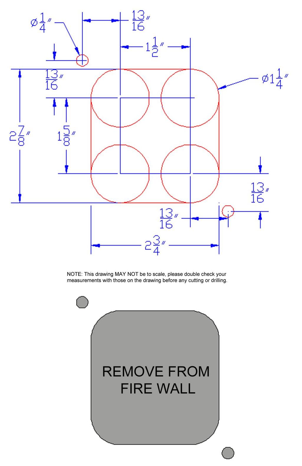
29 Use this template to check the opening in your firewall for the bulkhead connector. Due to variance in production tolerances, your firewall may have to be modified slightly. 23
30
31 Bulkhead Template for Vehicles with No Bulkhead Hole The dimension photo on the previous page shows how you can cut the bulkhead hole clean and precise using a 1 ¼ hole saw to cut 4 holes, using a jigsaw or cut off wheel to connect the outsides of the 1 ¼ holes, and using a ¼ drill bit for the fuse block mounting holes. Mark the centers of all 6 holes (the 1 ¼ holes as well as the ¼ ) holes before any cutting is done. Painless Performance Limited Warranty and Return Policy Chassis harnesses & fuel injection harnesses units are covered under a lifetime warranty. All other products manufactured and/or sold by Painless Performance are warranted to the original purchaser to be free from defects in material and workmanship under normal use. Painless Performance will repair or replace defective products without charge during the first 12 months from the purchase date. No products will be considered for warranty without a copy of the purchase receipt showing the sellers name, address and date of purchase. You must return the product to the dealer you purchased it from to initiate warranty procedures.
Wire Harness Installation Instructions For Installing:
 Wire Harness Installation Instructions For Installing: #20106 Classic Plus Customizable Tri-Five Chevy Harness 28 Circuit #20107 Classic Customizable Tri-Five Chevy Harness 21 Circuit Manual #90553 Painless
WIRE HARNESS INSTALLATION INSTRUCTIONS
 WIRE HARNESS INSTALLATION INSTRUCTIONS For Installing: #10206 Classic Plus Customizable GM Pickup Chassis Harness 1967-72 28 Circuit Manual #90510 PERFECT PERFORMANCE PRODUCTS, LLC Painless Performance
Wire Harness Installation Instructions
 Wire Harness Installation Instructions For Installing: Part #50001 Race Car Kit/8 Circuit Part #50201 8 Switch Dash Mounted Panel Part #50202 8 Switch Roll Bar Mounted Panel Manual #90502 Painless Performance
Wire Harness Installation Instructions
 Wire Harness Installation Instructions For Installing: #10127 Customizable Mopar Chassis Harness 21 Circuit Manual #90542 Painless Performance Products, LLC 2501 Ludelle Street Fort Worth, TX 76105-1036
Wire Harness Installation Instructions
 Wire Harness Installation Instructions For Installing: Part #10143 Landcruiser / Scout Weatherproof Harness Manual #90548 Painless Performance Products Division Perfect Performance Products, LLC 2501 Ludelle
WIRE HARNESS INSTALLATION INSTRUCTIONS
 WIRE HARNESS INSTALLATION INSTRUCTIONS For Installing: #10205 Classic Plus Customizable GM Pickup Chassis Harness 1973-87 27 Circuit Manual #90507 Painless Performance Products, LLC 2501 Ludelle Street
Wire Harness Installation Instructions
 Wire Harness Installation Instructions For Installing: #20101 Classic Plus Customizable 67-68 Camaro/Firebird Harness - 24 Circuit Manual #90551 Painless Performance Products Division Perfect Performance
Wire Harness Installation Instructions
 Wire Harness Installation Instructions FOR INSTALLING: PART #10130 14 CIRCUIT MICRO FUSE BLOCK REMOTE MOUNT HARNESS Manual #90525 Painless Performance Products Division Perfect Performance Products, LLC
Modular Wire Harness Installation Instructions
 Modular Wire Harness Installation Instructions 10301 MODULAR 4-CIRCUIT CHASSIS HARNESS Manual #90529 Painless Performance Products Division Perfect Performance Products, LLC 2501 Ludelle Street, Fort Worth,
Wire Harness Installation Instructions
 Wire Harness Installation Instructions FOR INSTALLING: #10308 Basic Customizable Chassis Harness 18 Circuit Manual #90527 Painless Performance Products, LLC 2501 Ludelle Street Fort Worth, TX 76105-1036
Wire Harness Installation Instructions
 Wire Harness Installation Instructions For Installing: Part #10107 Wiring Harness (Land Cruiser, Scout/12 circuit) Manual #90535 Painless Performance Products Division Perfect Performance Products, LLC
Wire Harness Installation Instructions
 Wire Harness Installation Instructions For Installing: #10140 Customizable Weatherproof Chassis Harness 26 Circuit Manual #90531 Painless Performance Products, LLC 2501 Ludelle Street Fort Worth, TX 76105-1036
Wire Harness Installation Instructions
 Wire Harness Installation Instructions For Installing: #10112 Classic Customizable Chevy P/U Harness 19 Circuit Manual #90519 Perfect Performance Products, LLC Painless Performance Products Division 2501
Wire Harness Installation Instructions For Installing:
 Wire Harness Installation Instructions For Installing: #10120 Classic Customizable Trunk Mount Harness 21 Circuit #10220 Classic Plus Customizable Trunk Mount Harness 28 Circuit Painless Performance Products,
Wire Harness Installation Instructions
 Wire Harness Installation Instructions For Installing: #10101 Classic Customizable Harness-GM Keyed Column-21 Circuit #10102 Classic Customizable Harness-Non GM Keyed Column-21 Circuit #10103 Classic Customizable
WIRE HARNESS INSTALLATION INSTRUCTIONS
 WIRE HARNESS INSTALLATION INSTRUCTIONS For Installing: 22 Circuit Chassis Harness Kits #10105 Classic Customizable Jeep CJ ( 74-back) #10106 Classic Customizable Jeep CJ (75-later) Manual #90504 Painless
Wire Harness Installation Instructions
 Wire Harness Installation Instructions For Installing: #10123 Customizable Ford Color Coded Harness 21 Circuit Manual #90545 Painless Performance Products, LLC 2501 Ludelle Street Fort Worth, TX 76105-1036
Wire Harness Installation Instructions
 Wire Harness Installation Instructions FOR INSTALLING: PART #10108 20 CIRCUIT BRONCO HARNESS Manual #90521 Painless Performance Products Division Perfect Performance Products, LLC 2501 Ludelle Street,
WIRE HARNESS INSTALLATION INSTRUCTIONS. For Installing: Part # Circuit Universal CJ Jeep Harness ( ) Manual #90513
 Manual #90513") WIRE HARNESS INSTALLATION INSTRUCTIONS For Installing: Part #10110 12 Circuit Universal CJ Jeep Harness (1975-86) Manual #90513 Perfect Performance Products, LLC Painless Performance Division 2501 Ludelle
WIRE HARNESS INSTALLATION INSTRUCTIONS For Installing: Part #10110 12 Circuit Universal CJ Jeep Harness (1975-86) Manual #90513 Perfect Performance Products, LLC Painless Performance Division 2501 Ludelle
Wire Harness Installation Instructions
 Wire Harness Installation Instructions For Installing: Part #20120 14 Circuit Ford Mustang (1965-1966) Manual #90526 Perfect Performance Products, LLC Painless Performance Products Division 2501 Ludelle
Wire Harness Installation Instructions
 Wire Harness Installation Instructions For Installing: #20121 Direct Fit Mustang Chassis Harness 1967-1968 22 Circuit Manual #90556 Perfect Performance Products, LLC Painless Performance Products Division
jegs.com
 Contents Wiring Harness w/ Fuse Panel Installation Instructions Turn Signal Plug w/ Terminals 2 Headlight Plugs 3/4 Grommet 10 ¼ Terminals 4 Ring Terminals 10 Wire Ties Fusible Link 2 Screws & Nuts 2 Plastic
Wire Harness Installation Instructions
 Wire Harness Installation Instructions For Installing: Part #20120 22 Ford Mustang (1965-1966) Manual #90526 Perfect Performance Products, LLC Painless Performance Products Division 2501 Ludelle Street
Wire Harness Installation Instructions
 Wire Harness Installation Instructions For Installing: Part #20122 14 Circuit 1969 1970 Ford Mustang Manual #90557 Perfect Performance Products, LLC Painless Performance Products Division 2501 Ludelle
Trail Rocker Installation Instructions
 Trail Rocker Installation Instructions Manual #90580 For Installing Painless Part Numbers: 57000 and 57001 Painless Performance Products recommends you, the installer, read this installation manual from
INSTRUCTIONS. 20 Circuit Wiring Kit Instructions October 2009, Speedway Motors, Inc.
 1 MAIN FUSE PANEL The main fuse panel harness s designed to be mounted under the dash a the firewall in an area close to the steering column. The enclosed representation of the main dash harness shows
Trail Rocker Installation Instructions
 Trail Rocker Installation Instructions Manual #90581 For Installing Painless Part Numbers: 57002 Painless Performance Products recommends you, the installer, read this installation manual from front to
20 CIRCUIT ATO FUSE CENTER INSTALLATION INSTRUCTIONS
 2501 Ludelle Street Fort Worth, Texas 76105 817-244-6212 phone 817-244-4024 fax 800-423-9696 Tech E-Mail: painless@painlessperformance.com Web: www.painlessperformance.com 30003 20 CIRCUIT ATO FUSE CENTER
Track Rocker Installation Instructions
 Track Rocker Installation Instructions For Installing Painless Part Numbers: 58103: 8-Switch Customizable Track Rocker Switch Panel w/ Flanged Mount 58106: 6-Switch Customizable Track Rocker Switch Panel
Off-Road Switch Panel Installation Instructions
 Off-Road Switch Panel Installation Instructions 50330: Off-road 4 Toggle switches/dash Mount w/keyed Ignition Switch 50332: Off-road 6 Toggle switches/dash Mount w/keyed Ignition Switch Painless Performance
Installation Instructions
 Installation Instructions Part #40120 Perfect Performance Products, LLC Painless Performance Products Division 2501 Ludelle Street Fort Worth, TX 76105-1036 800-423-9696 phone 817-244-4024 fax Web Site:
Trail Rocker Installation
 Trail Rocker Installation Instructions Customizable Trail Rocker Control System For Installing Painless Part Number: 57100 Manual #90616 Painless Performance Products recommends you, the installer, read
Wire Harness Installation Instructions For Installing:
 Wire Harness Installation Instructions For Installing: #10117 Direct Fit 1967-77 F-Series Ford Truck Harness w/o es 21 Circuit or #10118 Direct Fit 1967-77 F-Series Ford Truck Harness w/ es 21 Circuit
accessory connection rear body connection 40G 17A instrument cluster and map lamp ground 150A,B 15A 14A Circuit Branch 500A fog lamp switch
 accessory rear body 19 9 11 instrument cluster and map 10A, 0 4 3 7 40G 18 30 17A 24 1A 14A 9 8A instrument cluster 4E 31 3 121 11 33 401 10A 39A 400 30 washer and wiper switch 93A, 94 93 glovebox, map
Track Rocker Installation Instructions
 Track Rocker Installation Instructions Customizable Track Rocker Control System For Installing Painless Part Number: 58100 Track Rocker Relay Center Manual #90641 Painless Performance Products recommends
Manual P/N Copyright Third Edition June 21, 2005
 P/N 60212, 60213, 60214 & 60215 1996-99 GM VORTEC WIRE HARNESS INSTALLATION INSTRUCTIONS Manual P/N 90524 Copyright 2003 Third Edition June 21, 2005 PAINLESS PERFORMANCE PRODUCTS 2501 Ludelle Street, Fort
Installation Instructions For 50330, 50331, 50332, and Off Road Switch Panels
 Installation Instructions For 50330, 50331, 50332, and 50333 Off Road Switch Panels 2501 Ludelle Street Fort Worth, Texas 76105 817-244-6212 Phone 817-244-4024 Fax 888-350-6588 Sales 800-423-9696 Tech
Installation Instructions. Part #65100
 Installation Instructions Part #65100 Perfect Performance Products, LLC Painless Performance Products Division 2501 Ludelle Street Fort Worth, TX 76105-1036 800-423-9696 phone 817-244-4024 fax Web Site:
CLASSIC UPDATE WIRING KIT
 by Randy Irwin 1955-57 CLASSIC UPDATE WIRING KIT Randy Irwin - Technical Writer Randy has been involved in the Chevy parts business for over 25 years. He is a wizard at creating, making and modifying custom
Mustang Classic Update Series Kit
 accessory rear body 19 9 11 instrument cluster and map 10A, 0 4 3 7 40G 18 30 17A 24 1A 14A 9C 8A instrument cluster 4E 31 3 121 11 401 10A 3 400 30 washer and wiper switch 93A, 93 glovebox, map light,
Wire Harness Installation Instructions Manual #90563
 Wire Harness Installation Instructions Manual #90563 For Installing: #10113 Direct Fit 1966-1977 Bronco Harness 28 Circuit w/switches Perfect Performance Products, LLC Painless Performance Products Division
40A A 40B. Horn Relay Connector. Brake Switch. Third Brake Light. Brake Switch. Brake Switch. Wires. page 3. Rear Body Feed Wires.
 Fuse Box Connections (viewed from underside) 4D 4C 4D 0 50 300 4C 43 7 39 3 6 4 93 A 2G 2F 2E 2D 2C 2B 2G 2F 2E 40 69A 2 1 5 27 69A 3A B 40A,B 11A,B 40A 156 Dimmer Dome Feed page 2 Horn Relay 2D 2 29 40B
INSTRUCTIONS Circuit Wiring Kit Instructions _2017. Fuse Box Connections. (viewed from underside) 2018, Speedway Motors, Inc.
 2018, Speedway Motors, Inc.") Fuse Box Connections (viewed from underside) 4D 4C 100 50 300 4D 4C 4B 4A 43 107 39 103 3B 2G 104 93 2F 2E 2D 2C 2B 40 69A 102 101 105 2G 2F 2E 3A A 2A B 40A,B 27 69A 106 201, Speedway Motors, Inc. 1 Fuse
Fuse Box Connections (viewed from underside) 4D 4C 100 50 300 4D 4C 4B 4A 43 107 39 103 3B 2G 104 93 2F 2E 2D 2C 2B 40 69A 102 101 105 2G 2F 2E 3A A 2A B 40A,B 27 69A 106 201, Speedway Motors, Inc. 1 Fuse
PIN BULKHEAD CONNECTOR KIT
 2501 Ludelle Street Fort Worth, Texas 76105 817-244-6212 Phone 817-244-4024 Fax 888-350-6588 Sales 800-423-9696 Tech E-mail: painless@painlessperformance.com Web: www.painlessperformance.com 40130 22 PIN
INSTRUCTIONS 12 Circuit Wiring Kit Instructions
 Fan 47 9 56 4 7 6 72 40 45 48 5 8 6 Gauge Power Temp Sender Headlight Power Power Radio Constant Power Instruments and Dash Rear of Vehicle Ignition and Lights Fuse Panel & Front of Vehicle Horn Alt Excitor
Trail Rocker Installation
 Trail Rocker Installation Instructions 4, 6, or 8 - Switch Customizable Trail Rocker Switch Panel w/ Flanged Mount For Installing Painless Part Number: 57103, 57106, & 57109 Manual #90636 Painless Performance
-----
 ----- - - -- - - -- - -- - - NOTE: #32 WIRE DOES NOT APPLY TO 8 AND 14 CIRCUIT HARNESSES ELECTRIC FAN #1 TO FAN SWITCH (GRAY) #21 TEMP. GAUGE (GREEN) #2 TO AC SWITCH (BLACK) JUMPER WIRE ALTERNATORS
P/N & GM LS1 FUEL INJECTION WIRE HARNESS INSTALLATION INSTRUCTIONS
 P/N 605 & 6053 00-04 GM LS1 FUEL INJECTION WIRE HARNESS INSTALLATION INSTRUCTIONS Manual P/N 90544 nd Edition July 014 PAINLESS PERFORMANCE PRODUCTS 501 Ludelle Street - Fort Worth, Texas 76105-1036 -
Classic Update Series
 Classic Update Series 1964-1966 Ford Mustang START HERE! PLEASE READ THIS EFORE STARTING INSTALLATION! This wiring kit is designed for ease of installation. Please read the guidelines below, EFORE STARTING
Wire Harness Installation Instructions Manual #90576 For Installing:
 Wire Harness Installation Instructions Manual #90576 For Installing: #20112 Direct Fit Camaro Harness 1970-73 #20113 Direct Fit Camaro Harness 1974-77 #20114 Direct Fit Camaro Harness 1978-81 All 26 Circuit
WIRE SYSTEM PRO15 ULTRA SMALL 15 FUSE 24 CIRCUIT 118 TERMINAL PANEL WIRE SYSTEM
 TECH UPPORT: 503.693.1918 WIRE YTEM WWW.KEEPITCLEANWIRING.COM PRO15 ULTRA MALL 15 FUE 24 CIRCUIT 118 TERMINAL PANEL WIRE YTEM IMPORTANT: The below instructions are referring to a general installation.
30107 & PACK & 6-PACK RELAY BANK
 30107 & 30108 2501 Ludelle Street Fort Worth, Texas 76105 817-244-6212 Phone 817-244-4024 Fax 888-350-6588 Sales 800-423-9696 Tech E-mail: painless@painlessperformance.com Web: www.painlessperformance.com
Perfect Performance Products, LLC Painless Performance Products Division 2501 Ludelle St. Fort Worth, Texas (800)
") Wire Harness Installation Instructions For Installing: Part # 65104 Into 1985-1992 (5.0 & 5.7L) TPI Engines Manual # 90536 Perfect Performance Products, LLC Painless Performance Products Division 2501
Wire Harness Installation Instructions For Installing: Part # 65104 Into 1985-1992 (5.0 & 5.7L) TPI Engines Manual # 90536 Perfect Performance Products, LLC Painless Performance Products Division 2501
Rear Body 40D 156A 24 17A 151 3D. 8A,8B,8C under hood light. Horn Relay 91
 fuse box as viewed from the wire entry side Mating connector is plugged into Power Accessory connector 40D Rear Body 19 18 9B 30 LH Courtesy Light 40A,D 4D, 43 156B,C 16 16A 4C 3D 3C 16A 3G 4B 3G 116 4A&130
Wire Harness Installation Instructions
 Wire Harness Installation Instructions For Installing: Part #60101 - GM 86-93 TBI Standard Harness & Part #60201 GM 86-93 TBI Extended Length Harness Manual # 90503 Painless Performance Products, LLC 2501
Classic Update Series
 Classic Update Series 73-79 Ford F100-350 & 78-9 Ford ronco START HERE! PLEASE READ THIS EFORE STARTING INSTALLATION! This wiring kit is designed for ease of installation. Please read the guidelines below,
Headlight Switch Connector. Brake Switch. Lead Wires. Main Power Feed from Starter. Fuse Box Connections (viewed from underside)
") www.americanautowire.com 86-933-0801 TH KT DOE NOT UPPORT TOCK (ORGNAL) GENERATOR. THE DEGN OF THE KT DEGNED TO UPPLY MORE POWER THAN THE GENERATOR ALE TO UPPLY. 16 68A 4D 4C 4D 0 0 0 4C 4 43 7 39 3 Dimmer
www.americanautowire.com 86-933-0801 TH KT DOE NOT UPPORT TOCK (ORGNAL) GENERATOR. THE DEGN OF THE KT DEGNED TO UPPLY MORE POWER THAN THE GENERATOR ALE TO UPPLY. 16 68A 4D 4C 4D 0 0 0 4C 4 43 7 39 3 Dimmer
For Installing Harness Number: Manual #90627
 Wire Harness Installation Instructions For Installing Harness Number: 20205: 27 Circuit 1973-1987 GM Truck Manual #90627 Painless Performance Products recommends you, the installer, read this installation
Installation Instructions. Manual # For Installing: Part # Painless Gauge Controller
 Installation Instructions Manual #90579 For Installing: Part #60650- Painless Gauge Controller Perfect Performance Products, LLC Painless Performance Products Division 2501 Ludelle Street Fort Worth, TX
Wire Harness Installation Instructions Manual #90571 PART 1 For Installing: #10309 Basic Customizable Nostalgia All Black Chassis Harness 17 Circuit
 Wire Harness Installation Instructions Manual #90571 PART 1 For Installing: #10309 Basic Customizable Nostalgia All Black Chassis Harness 17 Circuit Painless Performance Products recommends you, the installer,
ISIS Power Manual and Installation Guide Race Car Replicas- Superlite Coupe
 ISIS Power Manual and Installation Guide Race Car Replicas- Superlite Coupe Table of Contents Overview... 2 System Details... 3 Kit Includes... 3 Technical Specifications... 3 Harness Descriptions... 4
P/N & GM LS1 FUEL INJECTION WIRE P/N & GM LS1 FUEL INJECTION WIRE HARNESS INSTALLATION INSTRUCTIONS
 P/N 60506 & 60507 1997-98 GM LS1 FUEL INJECTION WIRE HARNESS INSTALLATION INSTRUCTIONS P/N 60508 & 60509 1999-0 GM LS1 FUEL INJECTION WIRE HARNESS INSTALLATION INSTRUCTIONS Manual P/N 9050 Seventh Edition
Classic Update Series
 Classic Update Series 0-4 Ford Falcon and 0- Mercury Comet end view of terminal START HERE! PLEASE READ THIS EFORE STARTING INSTALLATION! This wiring kit is designed for ease of installation. Please read
Trail Rocker Installation Instructions
 Trail Rocker Installation Instructions Trail Rocker - Genesis Bracket For Installing Painless Part Number: 57200 Manual # 90591 To be used with Painless Kit # s: 57000-57005 Painless Performance Products
P/N & GM LS2 FUEL INJECTION WIRE HARNESS INSTALLATION INSTRUCTIONS. Manual P/N 90543
 P/N 6050 & 6051 005-06 GM LS FUEL INJECTION WIRE HARNESS INSTALLATION INSTRUCTIONS Manual P/N 90543 1 Painless Performance Products, LLC 501 Ludelle Street Fort Worth, TX 76105-1036 800-43-9696 phone 817-44-404
AIR CONTROL ACCESSORY KIT
 RAPID RESPONSE SYSTEM 2283 AIR CONTROL ACCESSORY KIT INSTALLATION INSTRUCTIONS Congratulations on your purchase of a new Air Control Accessory Kit. This kit was designed to provide inflation control of
INSTALLATION INSTRUCTIONS
 INSTALLATION INSTRUCTIONS Accessory Application Publications No. CIVIC AII 24171 S 2- AND 4-DOOR Issue Date (DX, HX) AUG 2002 NOTE: Fog Lights cannot be installed if the vehicle is equipped with an optional
Instrument Cluster 30 33B 39B A B C D E F E F G H J. Connector. Circuit Branch #4. Circuit Branch #5. Circuit. Branch #6 150A. Ground.
 16 4D, 43 4B 4A & 130 100 50 39A,B,C 300 4C 4B 4C 107 3C 3D 3C 3G 3B 3F 3A 16A 3G 116 104 93 3B 3D 2E 16A 2C 2D 2B 2A 44 40 27A 40B 115 27 40A,C,E 8A,B,C Mating is plugged into accessory connector Power
P/N & GM LS1 w/mechanical (cable) THROTTLE BODY FUEL INJECTION WIRE HARNESS INSTALLATION INSTRUCTIONS
 THROTTLE BODY FUEL INJECTION WIRE HARNESS INSTALLATION INSTRUCTIONS") P/N 60508 & 60509 1997-0 GM LS1 w/mechanical (cable) THROTTLE BODY FUEL INJECTION WIRE HARNESS INSTALLATION INSTRUCTIONS Manual P/N 9050 Painless Performance Products, LLC 501 Ludelle Street Fort Worth,
P/N 60508 & 60509 1997-0 GM LS1 w/mechanical (cable) THROTTLE BODY FUEL INJECTION WIRE HARNESS INSTALLATION INSTRUCTIONS Manual P/N 9050 Painless Performance Products, LLC 501 Ludelle Street Fort Worth,
INSTALLATION INSTRUCTIONS
 INSTALLATION INSTRUCTIONS Accessory Application Publications No. S CIVIC 2 AND 4-DOOR (EX, LX) AII 24188 Issue Date AUG 2002 NOTE: Fog Lights cannot be installed if the vehicle is equipped with an optional
P/N & /1995 GM LT1 FUEL INJECTION WIRE HARNESS INSTALLATION INSTRUCTIONS
 P/N 60502 & 60505 1994/1995 GM LT1 FUEL INJECTION WIRE HARNESS INSTALLATION INSTRUCTIONS Manual P/N 90517 Copyright May 2002 PAINLESS PERFORMANCE PRODUCTS 2501 Ludelle Street - Fort Worth, Texas 76105-1036
UNIVERSAL GAUGE WIRE HARNESS
 2650-1797-00 UNIVERSAL GAUGE WIRE HARNESS For Installing Auto Meter Electric Speedometer, Tachometer, And Short Sweep Electric Oil Pressure, Water Temperature, Fuel Level, and Volt Meter Gauges. This harness
Classic Update Series
 Classic Update Series 62-65 Ford Fairlane and 62-63 Mercury Meteor end view of terminal START HERE! PLEASE READ THIS EFORE STARTING INSTALLATION! This wiring kit is designed for ease of installation. Please
INSTALLATION INSTRUCTIONS
 Accessory Application Publications No. INSTALLATION INSTRUCTIONS S (DX, HX, VP) 2005 CIVIC 2- AND 4- DOOR AII 27865-30866 Issue Date SEP 2005 NOTE: Fog Lights cannot be installed if the vehicle is equipped
29048, 29049, 29050, 29051, 29052, 29053, 29054,
 April 15, 2014 Lit. No. 29225, Rev. 11 29048, 29049, 29050, 29051, 29052, 29053, 29054, 29400 5 HARNESS KIT 3 PORT ISOLATION MODULE LIGHT SYSTEM w/2 PLUG SYSTEM HARNESSES Installation Instructions Read
Part # GM LS2, 3 & 7-95mm Throttle Body
 Part # 65303 2006-2011 GM LS2, 3 & 7-95mm Throttle Body Perfect Performance Products, LLC 2501 Ludelle St. Fort Worth, Texas 76105 (800) 423-9696 1 We are always concerned about any corrections or improvements
INSTALLATION INSTRUCTIONS
 INSTALLATION INSTRUCTIONS Accessory Application Publications No. All 27176-28932 2005 CR-V Issue Date S P/N 08V31-S9A-115 FEB 2005 PARTS LIST 6 Washer-bolts Left fog light 6 Spring nuts Harness bracket
8436, 8437, 8438, 8439, 8442, 27480, 27780, 28028, & ISOLATION MODULE ELECTRICAL SYSTEM
 September 11, 2003 Lit. No. 27808 8436, 8437, 8438, 8439, 8442, 27480, 27780, 28028, & 28400 ISOLATION MODULE ELECTRICAL SYSTEM Installation Instructions Read this document before installing the snowplow.
Xtreme Air Command. Step 1 Prepare the components. Step 2 Select a mounting location. Parts list
 2549 60 90 400 600 30 200 120 800 psi 1000 kpa PSI 0 150 Xtreme Air Command Installation instructions Congratulations on your purchase of a new Xtreme Air Command kit. This kit was designed to provide
Vortec Drive by Cable Electronic Fuel Injection Wiring Harness (P/N HAR-1018) HAR-1018
 HAR-1018") 1998 2002 Vortec Drive by Cable Electronic Fuel Injection Wiring Harness (P/N HAR-1018) HAR-1018 PERFORMANCE SYSTEMS INTEGRATION 170 Oberlin Ave N Suite 13 Lakewood NJ 08701-4548 Ph: 732-444-3277 Email:
1998 2002 Vortec Drive by Cable Electronic Fuel Injection Wiring Harness (P/N HAR-1018) HAR-1018 PERFORMANCE SYSTEMS INTEGRATION 170 Oberlin Ave N Suite 13 Lakewood NJ 08701-4548 Ph: 732-444-3277 Email:
headlights [H only] dip switch hi beam flasher pillar interior lights rear interior panel switch C/D cubby A B boot map light LED strip
![headlights [H only] dip switch hi beam flasher pillar interior lights rear interior panel switch C/D cubby A B boot map light LED strip](/thumbs/74/70768506.jpg "headlights [H only] dip switch hi beam flasher pillar interior lights rear interior panel switch C/D cubby A B boot map light LED strip") to Alpine unit exterior lights [S or H or F] FUSE BOX LIGHTS ENGINE ACC reverse light, brake Note: diode (6a 50v) prevents triggering of Alpine backup camera when brake light is closed brake L tail plate
to Alpine unit exterior lights [S or H or F] FUSE BOX LIGHTS ENGINE ACC reverse light, brake Note: diode (6a 50v) prevents triggering of Alpine backup camera when brake light is closed brake L tail plate
Perfect Performance Products, LLC Painless Performance Products Division 2501 Ludelle St. Fort Worth, Texas (800)
") PERFECT HI-VELOCITY 68MM THROTTLE BODY Installation Instructions Part # 65301 1991-1998 Jeep 4.0L Engines w/perfect Engine Management System P/N 65140, 65141 OR All Jeep 4.0L Engines in Cherokee, Grand
PERFECT HI-VELOCITY 68MM THROTTLE BODY Installation Instructions Part # 65301 1991-1998 Jeep 4.0L Engines w/perfect Engine Management System P/N 65140, 65141 OR All Jeep 4.0L Engines in Cherokee, Grand
Installation Instructions
 Installation Instructions Jeep JK Unlimited (2007 Present) Mounting Bracket and Air Line System Kit for ARB On-Board Twin Air Compressor (CKMTA12) Made in the USA Kit Contents: 1 Bracket for ARB Compressor
Wire Harness Installation Manual # Part # 60617
 Wire Harness Installation Manual #90572 For Installing: Part # 60617 26 Circuit/7 Relay 4.8L-6.0 L w/4l60e Integrated Harnesses Perfect Performance Products, LLC Painless Performance Products Division
Opel Manta/Ascona/1900 Wiring Diagram (Based on using Universal EZ20 wiring harness)
") Opel Manta/Ascona/1900 Wiring Diagram (Based on using Universal EZ20 wiring harness) Index: 1 - Notes, egend, & Shipping Check ist i thru v - Instructions, Dos and Don'ts 2 - Fuse Box Diagram 3 - Front
Opel Manta/Ascona/1900 Wiring Diagram (Based on using Universal EZ20 wiring harness) Index: 1 - Notes, egend, & Shipping Check ist i thru v - Instructions, Dos and Don'ts 2 - Fuse Box Diagram 3 - Front
Turn Signal Kit Installation Instructions for Model A Fords & Other Antique Vehicles
 Turn Signal Kit Installation Instructions for Model A Fords & Other Antique Vehicles Lifetime Technical Support support@logolites.com 770-476-7322 www.logolites.com Manual 100-0005N Thank you for purchasing
PERFECT HI-VELOCITY 62MM THROTTLE BODY
 PERFECT HI-VELOCITY 62MM THROTTLE BODY Installation Instructions Part # 65300 1991-1998 Jeep 4.0L Engines OR All Jeep 4.0L Engines in Cherokee, Grand Cherokee and Wrangler 1991-2005 w/4 wire IAC ONLY.
Classic Update Series
 Classic Update Series 67-72 Ford Truck START HERE! PLEASE READ THIS EFORE STARTING INSTALLATION! This wiring kit is designed for ease of installation. Please read the guidelines below, EFORE STARTING your
29048, 29049, 29050, 29051, 29052, 20953, 29054,
 July 15, 2008 Lit. No. 29225, Rev. 06 29048, 29049, 29050, 29051, 29052, 20953, 29054, 29400-2 HARNESS KIT 3-PORT ISOLATION MODULE LIGHT SYSTEM w/2-plug SYSTEM HARNESSES Installation Instructions Read
DASH/MAIN HARNESS. NOTE: wires 400 & 401, must be twisted together.
 Electric Speedo Ground 151 Turn Flasher 16A 4 150 8A, Cluster Connections 31 33 30 35 151 (electric speedo) 402 401 NOTE: wires 400 & 401, must be twisted together. 156D, E Panel Dimmer 8A 9, C 2D Headlight
UNIVERSAL WIRING HARNESS Installation Manual
 UNIVERSAL WIRING HARNESS Installation Manual Terminals are provided for most connections on your wiring kit. Following the gauge manufacturer s instructions, use the terminals supplied with your gauge
Cutlass & F85. Oldsmobile. Wiring Harnesses. item# year description price. Cutlass/F85 PHONE YOUR ORDER FAX YOUR ORDER
 866-405-1367 207 AIR CONDITIONING HARNESSES 06045 1964-1964 AIR CONDITIONING HARNESS, V8 $118.00 09370 1965-1965 AIR CONDITIONING HARNESS, V8 $118.00 09450 1966-1966 AIR CONDITIONING HARNESS, V8 $118.00
INSTALLATION INSTRUCTIONS
 INSTALLATION INSTRUCTIONS Accessory Application Publications No. S P/N 08V31-SCV-102 2008 ELEMENT AII 36531 Issue Date MAY 2007 PARTS LIST 15 Wire ties 2 Fog lights 4 Wire ties with clip Switch harness
Perfect Performance Products, LLC Painless Performance Products Division 2501 Ludelle St. Fort Worth, Texas (800)
") PERFECT HI-VELOCITY 62MM THROTTLE BODY Installation Instructions Part # 65302 2005-2006 Jeep 4.0L All Jeep 4.0L Engines in Cherokee, Grand Cherokee, Wrangler and Rubicon. Perfect Performance Products,
PERFECT HI-VELOCITY 62MM THROTTLE BODY Installation Instructions Part # 65302 2005-2006 Jeep 4.0L All Jeep 4.0L Engines in Cherokee, Grand Cherokee, Wrangler and Rubicon. Perfect Performance Products,
Installation Instructions For 50340
 Installation Instructions For 50340 2501 Ludelle Street Fort Worth, Texas 76105 817-244-6212 Phone 817-244-4024 Fax 888-350-6588 Sales 800-423-9696 Tech E-mail: painless@painlessperformance.com Web: www.painlessperformance.com
INSTALLATION INSTRUCTIONS
 INSTALLATION INSTRUCTIONS Accessory Application Publications No. All 27176 2005 CR-V Issue Date P/N 08V31-S9A-114 SEP 2004 PARTS LIST 25 Wire ties Left fog light 6 Washer-bolts Right fog light 6 Spring
INSTALLATION INSTRUCTIONS
 INSTALLATION INSTRUCTIONS Accessory Application Publications No. All 26124 CR-V Issue Date SEP 2003 P/N 08V31-S9A-112 PARTS LIST 4 Washer-bolts, 6 x 20 mm Left fog light 2 Small spring nuts Right fog light
INSTALLATION INSTRUCTIONS
 INSTALLATION INSTRUCTIONS Accessory Application Publications No. P/N 08V31-SNA-100 2007 CIVIC HYBRID AII 33829 Issue Date SEP 2006 PARTS LIST Fog light harness Right fog light Left fog light Subharness
Headlight Switch Connector. Brake Switch. Lead Wires. Main Power Feed from Starter. Fuse Box Connections (viewed from underside)
") 0 Heller Pl #17 W ellmawr, NJ 0031 6-933-001 TH KT DOE NOT UPPORT TOCK (ORGNL) GENERTOR. THE DEGN OF THE KT DEGNED TO UPPLY MORE POWER THN THE GENERTOR LE TO UPPLY. 16 6 4D 4C 4D 0 0 0 4C 4 4 43 7 39 3
0 Heller Pl #17 W ellmawr, NJ 0031 6-933-001 TH KT DOE NOT UPPORT TOCK (ORGNL) GENERTOR. THE DEGN OF THE KT DEGNED TO UPPLY MORE POWER THN THE GENERTOR LE TO UPPLY. 16 6 4D 4C 4D 0 0 0 4C 4 4 43 7 39 3
INSTALLATION INSTRUCTIONS
 Accessory Application Publications No. INSTALLATION INSTRUCTIONS S (LX, EX) CIVIC 2- AND 4- DOOR AII 25449 Issue Date SEP 2003 NOTE: Fog Lights cannot be installed if the vehicle is equipped with an optional