ATASA 5 th. ATASA 5 TH Study Guide Chapter 20 Pages Lighting Systems 43 Points. Please Read The Summary
|
|
|
- Raymond Flynn
- 6 years ago
- Views:
Transcription


1 ATASA 5 TH Study Guide Chapter 20 Pages Points Please Read The Summary

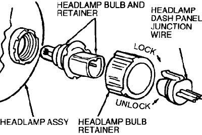
2 1. The lighting system provides power to both the and lights. Front & Rear Interior & Exterior Manual & Automatic
3 2. A or bulb generates light as current flow through the filament. Lamp Camp Stamp


4 3. The glass envelope around the filament is evacuated to the filament burns in a. Fluid Pressure Vacuum


5 4. Lamps can be or filament and can vary in their wattage rating. Triple or Dual Single or Married Single or Double

6 5. Sealed beam headlights are airtight & normally filled with gas. They consist of a filament, concave reflector and lens. Carbon Argon Neon


7 6. A sealed beam headlight is commonly filled with iodine gas. It can withstand higher temperatures and burn brighter than those filled with argon. Halogen Argon Iodine
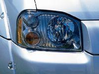
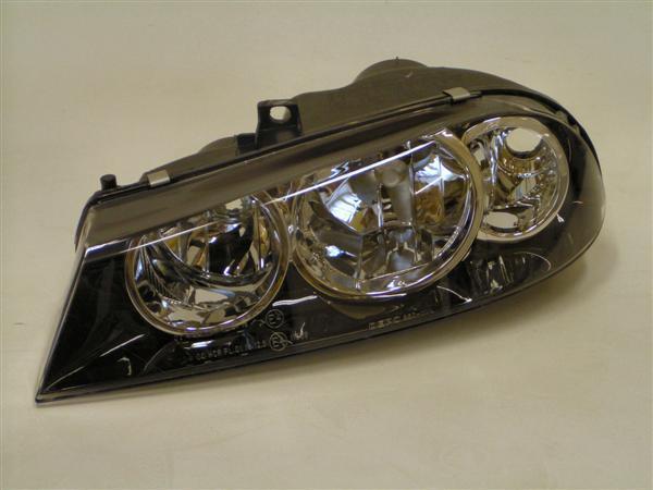

8 7. Headlights with a replaceable bulb are called headlights. Deposit Composite Aerodynamic


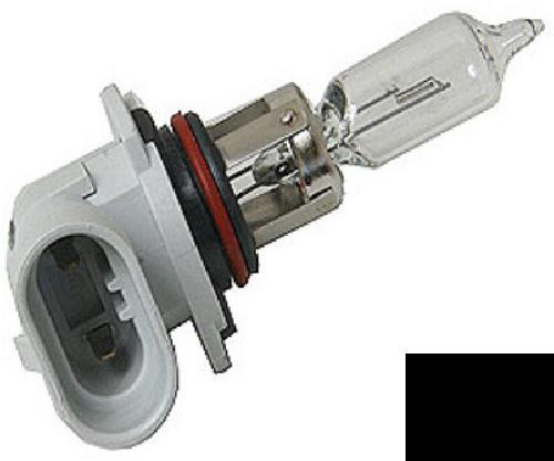
9 8. Bulb life can be shortened if you touch the bulb s envelope with your.

10 9. (HID) have a blue white color, close to daylight, and make their light by arcing electricity between 2 electrodes that excite xenon gas. (15,000 volts!) High Identity Demand High Intensity Discharge Highly Intense Dominoes


11 10. Xenon headlights produce as much light, use 2/3 less power, and last 2 to 3 times as long as regular halogen headlights. Initial cost is higher. Uno Twice Thrice


12 11. Bi Xenon systems have HID for low & high beam and a halogen for. Flash to Pass Flash to Warn Flash to Flash
 as")


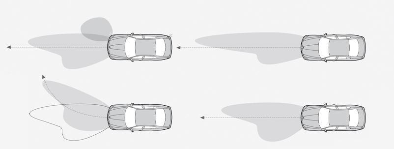
13 12. LED lights use (semi conductors) as their source of light. Light Amplifying Diodes Light Demanding Diodes Light Emitting Diodes


14 13. The switch is a multi function switch for headlights, parking lights, fog lights, and in some cases, contains a rheostat to control instrument panel/cluster brightness. Headlight Stoplight

15 14. The switch is used to switch from bright to dim, operate the flash to pass feature and in some cases, functions as the turn signal switch. Dimmer Simmer Trimmer
16 15. (DRL) operate the headlights at a reduced voltage anytime the vehicle is running in daylight. Applying the parking brake turns the DRLs off. Daytime Running Lights


17 Huge Safety Note The parking lights in front & the running lights in the rear are not on if the DRL s are on!! Daytime Running Lights


18 16. Automatic lights use a sensor that determines the ambient light level & automatically turns on the headlight system if surrounding light is too dim. (dusk, in a tunnel, cloudy, etc.)
 & running")


19 Huge Safety Note: Parking lights (front) & running lights (rear) are not on if DRLs are on!! So the best advice is to Turn on Your Headlights Whenever you drive!
20 17. A headlight system keeps the lights on for some period of time after ignition is shut off. Decay Relay Delay

21 18. High Beam systems turn on the high beam lights for better visibility when no vehicles are sensed in front of or behind the car. Light sensors called cameras are used to detect. Detection Reaction Rejection


22 19. headlights aim in the direction that the vehicle is turning. Adaptive Reactive Proactive

23 The back up light switch may be part of the park/neutral switch.

24 20. lights, that are aimed under the fog, and driving lights are considered auxiliary lights. Frog Fog Grog
25

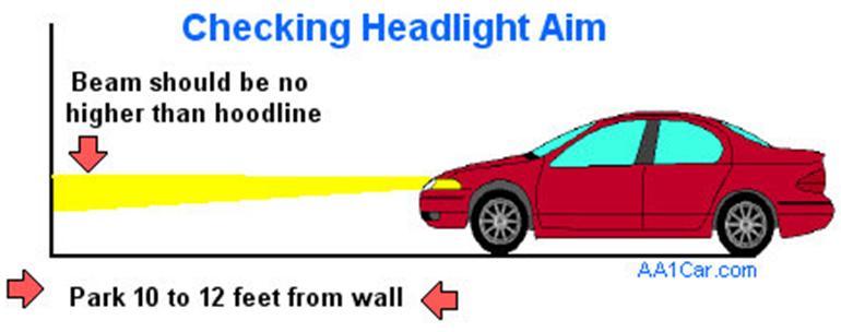
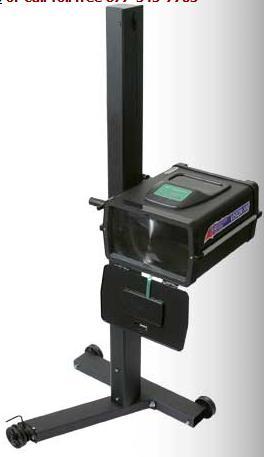
26 21. Headlights can be or adjusted to provide the proper nighttime view of the road. Some vehicles with xenon lamps have an auto leveling feature that functions with the suspension. Aimed Pointed Sighted
27
 to ensure the exact replacement.")
28 22. When replacing bulbs, check the rating (wattage) to ensure the exact replacement. Amps Watts Volts
29 23. Lighting can be either side switched or side switched. (check schematics) Power or Ground Inside or Outside Automatic or Manual

30 24. lights include: engine compartment, glove box, luggage compartment, vanity, dome or map, courtesy, and illuminated entry of the lock cylinder & puddle lamps under the mirror. Interior Exterior Mood

31 25. Rear lighting includes:,, back up/reverse, parking lights &. Turn, Stop, Hazard Brake, Parking, Side Marker Stop, Yield, Go


32 Flash to pass illuminates high beams with a pull of the dimmer switch.

33 Interior light options include illuminated entry & delayed shut off.


34 Multi Function switches control more than one circuit.


35 26. are circuit breaking components of the turn signal & hazard warning systems. Dasher Flasher Thrasher
36 27. Flashers operate (cycle on & off) with the in the system & can blink too fast or too slow. Current Voltage Resistance

37 28. If additional bulbs are used, like with a trailer attached, a flasher is needed. More bulbs lower the parallel resistance causing the flasher to cycle so fast, it seems constantly on. Low Duty Medium Duty Heavy Duty

38 29. If a bulb is burned out, the flasher will cycle. Faster Slower Not At All


39 30. Brake lights are controlled by the switch, usually located on the pedal bracket. Stoplight Red light Green light
 Center High Mount")

40 31. The brake lights also have a (CHMSL) Center High Mount Stop Lamp Center High Mount Slip Lamp Center High Mount Slime Lamp


41 32. LEDs used as rear lighting offer the advantage of full brightness in millisecond vs. 200 msec. 1 msec 10 msec 100 msec

42 33. Adaptive brake lights increase their intensity or surface area when intervention is on. SIR/SRS ATC ABS

43 34. lights are clear, rear lights that turn on when the transmission is placed in reverse. They are controlled by a transmission mounted back up light switch or transmission range switch. Back up Get up Stand up


44 35. Simple bulb is often the answer to a lamp out situation. Rebuilding Replacement Remanufacturing

45 36. Loose or corroded & connectors can cause lights out, intermittent operation, low intensity & flickering. Remember: Resistance up = Amps down Sockets Lockets Pockets


46 38. Shorts to ground in wiring, connectors, or in a bulb will increase current flow & blow a. Gasket Fuse Blood Vessel

47 39. High resistance due to corrosion will reduce flow and the intensity of the bulb. This can occur in either the hot side or the ground side of the circuit. Diagnose with voltage drop tests. Wattage Voltage Current
Always obey local vehicle lighting laws. The driver is always responsible for the correct headlight settings.
 Lights Introduction In this section you ll find information about: Indicator lights Turn signal lever and high beam switch Switching lights on and off Lights and vision features Lights and vision features
Exterior Lighting Systems Description and Operation. Exterior Lamps. The exterior lighting system consists of the following lamps: The headlamps
 Exterior Lighting Systems Description and Operation Exterior Lamps The exterior lighting system consists of the following lamps: The headlamps The daytime running lamps (DRL) The front fog lamps The park,
EXTERIOR LAMPS - OPERATION
 2013 Dodge or Ram Truck Journey FWD L4-2.4L Vehicle > Lighting and Horns > Description and Operation > Components EXTERIOR LAMPS - OPERATION OPERATION Following are paragraphs that briefly describe the
TEST SPECIFICATIONS AND TASK LIST ELECTRICAL/ELECTRONIC SYSTEMS (TEST A6)
") TEST SPECIFICATIONS AND TASK LIST ELECTRICAL/ELECTRONIC SYSTEMS (TEST A6) Content Questions Percentage Area in Test of Test A. General Electrical/Electronic System 13 26% Diagnosis B. Battery Diagnosis
TEST SPECIFICATIONS AND TASK LIST ELECTRICAL/ELECTRONIC SYSTEMS (TEST A6) Content Questions Percentage Area in Test of Test A. General Electrical/Electronic System 13 26% Diagnosis B. Battery Diagnosis
Handout Activity: HA802
 Lighting system HA802-2 Handout Activity: HA802 Lighting system The lighting system provides a means of allowing the driver to both see when driving in poor visibility conditions and to provide a means
Lighting GENERAL INFORMATION. Daytime running lamps. Halogen headlamps. Stop lamps. Bi-Xenon headlamps. Reversing lamps
 Lighting GENERAL INFORMATION There are three types of headlamp systems: Halogen high/low beam main lamp with a fill-in high beam halogen lamp alongside. Bi-xenon high/low beam main lamps with fill-in high
Lighting LIGHTING CONTROL FRONT FOG LAMPS. Main switch panel. Headlamp courtesy delay. Main beam
 Lighting LIGHTING CONTROL Main switch panel. To flash the headlamps at anytime, briefly pull the indicator stalk and release it. When the headlamp main beam is on, the main beam warning indicator will
SECTION 9B LIGHTING SYSTEMS
 SECTION 9B LIGHTING SYSTEMS CAUTION: Disconnect the negative battery cable before removing or installing any electrical unit or when a tool or equipment could easily come in contact with exposed electrical
Lighting GENERAL INFORMATION. Daytime running lamps. Condensation. Stop lamps. Halogen headlamps. Reversing lamps. Bi-Xenon headlamps
 Lighting GENERAL INFORMATION There are three types of headlamp systems: Halogen high/low beam main lamp with a fill-in high beam halogen lamp alongside. Bi-xenon high/low beam main lamps with fill-in high
Onboard power supply management
 Onboard power supply management The onboard power supply J519 Functions of onboard power supply control unit Until now s and relays functioned at different locations in the vehicle. In the onboard power
Part 1 OPERATION OF INSTRUMENTS AND CONTROLS
 Part 1 OPERATION OF INSTRUMENTS AND CONTROLS Chapter 1-4 Lights, Wipers and Defogger Headlights and turn signals Emergency flashers Instrument panel light control Front fog lights Interior lights Ignition
1. LAMP SPECIFICATIONS
 8310-00 07-3 1. LAMP SPECIFICATIONS 1) Exterior Lamps Description Numbers Specification Headlamp High beam 2 H1-55W Low beam 2 H7-55W Turn signal lamp 2 P21W Position lamp - LED Front fog light 2 H16-19W
LAMPS 8L - 1 LAMPS CONTENTS
 TJ LAMPS 8L - 1 LAMPS CONTENTS BULB APPLICATION... 16 HEADLAMP ALIGNMENT... 5 LAMP BULB SERVICE... 8 LAMP DIAGNOSIS... 1 LAMP SERVICE... 11 LAMP SYSTEMS... 15 LAMP DIAGNOSIS INDEX GENERAL INFORMATION GENERAL
Exterior Lighting ! WARNING: MASTER LIGHTING SWITCH. Headlights
 MASTER LIGHTING SWITCH Headlights! WARNING: It is an offence in certain countries to obscure front and rear lights, direction indicators and reflectors. Lighting positions The exterior lights are controlled
1. SPECIFICATIONS OF LAMPS
 831000 103 1. SPECIFICATIONS OF LAMPS Exterior Lamps Description Numbers GEN EU Headlamp High beam 2 55W 55W/15W Front combination lamp Outside turn signal lamp (supplemental turn signal lamp) Rear combination
FUSE DETAILS. Fuse Details
 2003 Jaguar S-Type (X200) V8-4.2L Vehicle > Power and Ground Distribution > Fuse > Application and ID > Components FUSE DETAILS Fuse Details https://my.alldata.com/repair/#/repair/article/40444/component/1169/itype/389/nonstandard/1247914
Note: Do NOT mix LED and incandescent lamps in the same circuit!
 Light Up Your Modified Car Some Hot Rod lights are hard to see. Your teardrop lights may look cool, but the 5W incandescent lamp that came with it just doesn t light up bright enough to show others you
b) two pairs of dipped-beam headlamps if the vehicle was first registered anywhere between 1 January 1977 and 31 March 1980, or
 two pairs of dipped-beam headlamps if the vehicle was first registered anywhere between 1 January 1977 and 31 March 1980, or") Correct as at 23rd November 2013. It may be superseded at any time. Extract taken from: NZTA Vehicle Portal > VIRMs > In-service certification (WoF) > General vehicles > Lighting 4 Lighting 4-1 Headlamps
Correct as at 23rd November 2013. It may be superseded at any time. Extract taken from: NZTA Vehicle Portal > VIRMs > In-service certification (WoF) > General vehicles > Lighting 4 Lighting 4-1 Headlamps
Symptom Suspect Area See page. 11.Ignition Switch 12.Power Source Circuit. Symptom Suspect Area See page
 BE2 PROBLEM SYMPTOMS TABLE IGNITION SWITCH: BE18204 Ignition switch is not set to each position. KEY UNLOCK WARNING SWITCH: 11.Ignition Switch 12.Power Source Circuit BE15 Key unlock warning system does
SECTION 1 2 INSTRUMENTS AND CONTROLS. Switches
 SECTION 1 2 INSTRUMENTS AND CONTROLS Switches Headlight switch.......................................... 16 Headlight dimmer and turn signal switch..................... 17 Fog light switch...........................................
Symptom Suspected Area See page Ignition switch is not set to each position. 11.Ignition switch BE 14
 BE2 BODY ELECTRICAL PROBLEM SYMPTOMS TABLE IGNITION SWITCH AND KEY UNLOCK WARNING SWITCH BE0ON18 Ignition switch is not set to each position. 11.Ignition switch BE14 Key unlock warning system does not
LAMPS 8L - 1 LAMPS CONTENTS
 NS LAMPS 8L - 1 LAMPS CONTENTS BULB APPLICATION... 25 EXTERIOR LAMP BULB SERVICE... 9 EXTERIOR LAMP SERVICE... 14 HEADLAMP ALIGNMENT... 5 INTERIOR LAMPS... 18 LAMP DIAGNOSIS... 1 LAMP DIAGNOSIS INDEX GENERAL
POWER SOURCE (Current Flow Chart)
") POWER SOURCE (Current Flow Chart) The chart below shows the route by which current flows from the battery to each electrical source (Fusible Link, Circuit Breaker, Fuse, etc.) and other parts. The next
POWER SOURCE (Current Flow Chart) The chart below shows the route by which current flows from the battery to each electrical source (Fusible Link, Circuit Breaker, Fuse, etc.) and other parts. The next
EQUIPMENT - MAIN BODY 7-1 SECTION 7 EQUIPMENT CONTENTS
 EQUIPMENT - MAIN BODY 7-1 SECTION 7 EQUIPMENT CONTENTS Engine Immobiliser System...7-1 Exterior Lights...7-2 Combination Meter...7-2 Smart Wiring System (SWS)...7-3 General Information...7-3 Functions
LIGHTING. GROUP 54Ac. Continued on next page. 54Ac-1 CONTENTS. GENERAL INFORMATION...54Ac-5. SERVICE SPECIFICATIONS...54Ac-7. SPECIAL TOOLS...
 54Ac-1 GROUP 54Ac LIGHTING CONTENTS GENERAL INFORMATION...54Ac-5 SERVICE SPECIFICATIONS...54Ac-7 SPECIAL TOOLS...54Ac-8...54Ac-11 STANDARD FLOW OF DIAGNOSTIC TROUBLESHOOTING...54Ac-11 DIAGNOSTIC FUNCTION...54Ac-11
2000 Volkswagen Jetta GL
 Fig. 8: Locating Battery Fuse Panel Fuses Courtesy of VOLKSWAGEN UNITED STATES, INC. FUSE IDENTIFICATION (BATTERY FUSE PANEL) Fuse No. Amp Circuits Protected Rating 162 Engine Codes 50 Secondary Air Injector
FUSES & CIRCUIT BREAKERS
 FUSES & CIRCUIT BREAKERS FUSES & CIRCUIT BREAKERS 1989-95 FUSES & CIRCUIT BREAKERS Ford Motor Co. INTERIOR FUSE PANEL IDENTIFICATION (1983-88 MODELS) On all models, the fuse panel is located under the
ASE 6 - Electrical Electronic Systems. Module 16 Lighting Systems
 Electronic Systems Module 16 Acknowledgements General Motors, the IAGMASEP Association Board of Directors, and Raytheon Professional Services, GM's training partner for GM's Service Technical College wish
Pretest Module 15 Units 1, 2, 3, 4
 Pretest Module 15 Units 1, 2, 3, 4 1. What is the light-sensitive surface at the back of the eye? Retina 2. What is the transparent outer membrane surrounding the eye? Cornea 3. What four objective factors
Maintenance notice proceeding
 Maintenance notice proceeding When check, remove and replace car body electric relating parts, please pay attention to the proceedings below. 1. Lighting There is sealed gas in halogen bulb, so please
Diesel Technology: Electrical and Electronic Systems
 Diesel Technology: Electrical and Electronic Systems NATEF Crosswalk The following NATEF Electrical/Electronic Systems tasks (rev. 2001) are covered in this publication. The chart shows where each task
Key Explanation Key Explanation 1 Rain-light sensor (RLS) 2 Light switch
 2 Light switch") E60, E61, E63, E64 from 03/2005 - Light module with adaptive headlights From 03/2005, the adaptive headlights are integrated into the light module. Installation location The light module is installed in
E60, E61, E63, E64 from 03/2005 - Light module with adaptive headlights From 03/2005, the adaptive headlights are integrated into the light module. Installation location The light module is installed in
G ELECTRICAL WIRING ROUTING
 G ELECTRICAL WIRING ROUTING Position of Parts in Engine Compartment A 1 A/C Ambient Temp. Sensor A 2 A/C Condenser Fan Motor A 3 A/C Magnetic Clutch and Lock Sensor A 4 A/C Triple Pressure SW (A/C Dual
G ELECTRICAL WIRING ROUTING
 2 6 G ELECTRICAL WIRING ROUTING Position of Parts in Engine Compartment A1 A/C Front Magnetic Valve A3 A/C Magnetic Clutch A6 A/T Flud Temp. Sensor A7 ABS Actuator A8 ABS Actuator A10 ABS Speed Sensor
KENSUN HID AUTOMOTIVE HEAD LAMP CONVERSION KIT INSTALLATION MANUAL
 1 KENSUN HID AUTOMOTIVE HEAD LAMP CONVERSION KIT INSTALLATION MANUAL 2 CONTENTS A. Before Installing B. Installing the Bulbs C. Installing the Ballasts D. For Bi Xenon Only: Installing the Relay Harness
G ELECTRICAL WIRING ROUTING
 G ELECTRICAL WIRING ROUTING Position of Parts in Engine Compartment A 1 A/C Condenser Fan Motor A 2 A/C Magnetic Clutch and Lock Sensor A 3 A/C Triple Pressure SW (A/C Dual and Signal Pressure SW) A 4
SECTION CONTENTS ELECTRICAL LT-1
 K ELECTRICAL A SECTION LIGHTING SYSTEM B C D CONTENTS E PRECAUTIONS... 3 Precautions for Supplemental Restraint System (SRS) AIR BAG and SEAT BELT PRE-TEN- SIONER... 3 Wiring Diagrams and Trouble Diagnosis...
Black plate (27,1) Index 14 北米Model "A3180BE-B" EDITED: 2014/ 2/ 7
 Index 14 北米Model A3180BE-B EDITED: 2014/ 2/ 7") Index 14 14-2 Index A Abbreviation... 3 ABS (Anti-lock Brake System)... 7-20 Warning light... 3-15, 7-21 Accessories... 5-2, 11-36 Accessory power outlet... 6-10 Active head restraint... 1-6 Air cleaner
Index 14 14-2 Index A Abbreviation... 3 ABS (Anti-lock Brake System)... 7-20 Warning light... 3-15, 7-21 Accessories... 5-2, 11-36 Accessory power outlet... 6-10 Active head restraint... 1-6 Air cleaner
2004 Acura TSX. Fig. 1: Dash Lights Brightness Controller Wiring Diagram
 Fig. 1: Dash Lights Brightness Controller Wiring Diagram Tuesday, March 11, 2008 10:57:55 PM Page 2 TURN SIGNAL/HAZARD FLASHER COMPONENT LOCATION INDEX Fig. 2: Locating Turn Signal/Hazard Flasher Components
LIGHTING SYSTEM PRECAUTION LI 1
 System Name Power Window Control System GHTING GHTING SYSTEM GHTING SYSTEM PRECAUTION 1 1. PRECAUTION FOR DISCONNECTING BATTERY CABLE NOTICE: FOR INITIAZATION: When disconnecting the cable from the negative
Pin assignments at plug connector A173*1B. Pin assignments at plug connector A173*2B
 FEM Connector location views Number X-pin, colour Description A173*1B 1-pin, black Component connector Front Electronic Module A173*2B 42-pin, black Component connector Front Electronic Module A173*3B
LIGHTING SYSTEM SECTION LT CONTENTS K ELECTRICAL LT-1
 K ELECTRICAL SECTION LT A LIGHTING SYSTEM B C D CONTENTS E PRECAUTIONS... 3 Precautions for Supplemental Restraint System (SRS) AIR BAG and SEAT BELT PRE-TEN- SIONER... 3 Wiring Diagrams and Trouble Diagnosis...
Choose the right light. automotive.tungsram.com
 Choose the right light automotive.tungsram.com Tungsram, one of Europe s most iconic lighting brands, has entered an exciting new phase in its history with the acquisition of GE Lighting s Europe, Middle
Electricity Simulation: Sound
 Electricity Simulation: Sound Activity One Introduction How do telephones and radios send sound so that we hear it? When anything vibrates, it produces sound. When sounds enter a microphone, the sound
Lamp TABLE OF CONTENTS
 TABLE OF CONTENTS Bulb Specifications and Functional Check...13-2 Location of Exterior Lamps...13-3 Replacing the Exterior Lamps...13-4 Replacing the Interior Lamps...13-6 13 Lamp 1 2 3 4 5 6 7 8 9 10
LIGHTING SYSTEM SECTION CONTENTS K ELECTRICAL LT-1
 K ELECTRICAL A SECTION LIGHTING SYSTEM B C D CONTENTS E PRECAUTIONS... 3 Precautions for Supplemental Restraint System (SRS) AIR BAG and SEAT BELT PRE-TEN- SIONER... 3 Wiring Diagrams and Trouble Diagnosis...
POWER SOURCE (Current Flow Chart)
") The chart below shows the route by which current flows from the battery to each electrical source (Fusible Link, Circuit Breaker, Fuse, etc.) and other parts. The next page and following pages show the
The chart below shows the route by which current flows from the battery to each electrical source (Fusible Link, Circuit Breaker, Fuse, etc.) and other parts. The next page and following pages show the
CHASSIS ELECTRICAL GROUP 54A 54A-1 CONTENTS COMBINATION METER... 54A-9 GENERAL DESCRIPTION... 54A-2 DIAGNOSTIC SYSTEM... 54A-2
 54A-1 GROUP 54A CHASSIS ELECTRICAL CONTENTS GENERAL DESCRIPTION 54A-2 DIAGNOSTIC SYSTEM 54A-2 BATTERY 54A-4 IMMOBILIZER SYSTEM 54A-4 LIGHTING 54A-6 COMBINATION METER 54A-9 RADIO, CD PLAYER, SPEAKER AND
Current, resistance and potential difference
 Multiple choice questions 1. Three conductors join as shown in the diagram. The direction of the current in each conductor is shown by the arrow. Y Z X The current in the conductor Z is 10 A. The current
(1,1) Index 14 北米Model "A1330BE-B" EDITED: 2017/ 11/ 30
 Index 14 北米Model A1330BE-B EDITED: 2017/ 11/ 30") Index 14 14-2 Index A Abbreviation... 3 ABS (Anti-lock Brake System)... 7-33 Warning light... 3-20 Access key fob... 2-3 Warning light... 3-25 Accessories... 11-37 Accessory power outlet... 6-7 Air cleaner
Index 14 14-2 Index A Abbreviation... 3 ABS (Anti-lock Brake System)... 7-33 Warning light... 3-20 Access key fob... 2-3 Warning light... 3-25 Accessories... 11-37 Accessory power outlet... 6-7 Air cleaner
Model A Ford Lighting Upgrades. How to get more light without doing permanent alterations.
 Model A Ford Lighting Upgrades How to get more light without doing permanent alterations. How to improve performance Install more powerful bulbs in lights. Recondition reflectors. Clean electrical connections.
Exterior Lights. How the Headlights Circuit Works USA. Flash-to-Pass WARNING
 Exterior Lights How the s Circuit Works USA WARNING A transient high tension (25,000 V) occurs at the bulb sockets of the high intensity discharge (HID) lamps when the combination light switch is turned
Position of Parts in Engine Compartment
 ELECTRICAL WIRING ROUTING [3S GTE] Position of Parts in Engine Compartment A 1 A/C Ambient Temp. Sensor D 1 Date Link Connector 1 (Check Connector) A 2 A/C Condenser Fan Motor D 2 Distributor A 4 A/C Magnetic
G ELECTRICAL WIRING ROUTING [1MZ-FE] Position of Parts in Engine Compartment
![G ELECTRICAL WIRING ROUTING [1MZ-FE] Position of Parts in Engine Compartment](/thumbs/87/97394184.jpg "G ELECTRICAL WIRING ROUTING [1MZ-FE] Position of Parts in Engine Compartment") G ELECTRICAL WIRING ROUTING [1MZ-FE] Position of Parts in Engine Compartment A 1 A/C Ambient Temp. Sensor A 2 A/C Condenser Fan Motor A 3 A/C Magnetic Clutch and Lock Sensor A 4 A/C Triple Pressure SW
G ELECTRICAL WIRING ROUTING [1MZ-FE] Position of Parts in Engine Compartment A 1 A/C Ambient Temp. Sensor A 2 A/C Condenser Fan Motor A 3 A/C Magnetic Clutch and Lock Sensor A 4 A/C Triple Pressure SW
Science Olympiad Shock Value ~ Basic Circuits and Schematics
 Science Olympiad Shock Value ~ Basic Circuits and Schematics Use a single D battery, a single bare wire and a light bulb. Find four different ways to light the light bulb using only a battery, one wire
SECTION Interior Lighting
 417-02-i Interior Lighting 417-02-i SECTION 417-02 Interior Lighting CONTENTS PAGE DIAGNOSIS AND TESTING Interior Lighting... 417-02-2 Principles of Operation... 417-02-2 Inspection and Verification...
Body Electrical System
 Body Electrical System GENERAL....BE -2 MULTI FUNCTION SWITCH...BE -8 HORN...BE -11 FUSES AND RELAYS...BE -12 INDICATORS AND GAUGES...BE -19 LIGHTING SYSTEM...BE -24 DAYTIME RUNNING LIGHTS...BE -30 BE-2
DMK, Inc Coye Drive Stevens Point, WI USA Phone: Fax:
 lighting 2 DMK provides a complete range of LED, HID, and halogen work lights designed for off-road applications. Work lights are developed in Family Groups so that OEMs can maintain a consistent design
Complete Guide to Xenon HID Lamps
 Complete Guide to Xenon HID Lamps Electric Arc No Filament Gas & Metallic Salts Sealed in Glass Tube Tungsten Electrode Integrated Starter D1S, D1R, D3S, D3R What Are Xenon HID Lamps HID systems (also
Ziza Interior Lighting Package Installation ES
 Installation Procedures Ziza Interior Lighting Package Installation for BMW E70 X5 This tutorial is provided as a courtesy by ECS Tuning. Proper service and repair procedures are vital to the safe, reliable
b) two pairs of dipped-beam headlamps if the vehicle was first registered anywhere between 1 January 1977 and 31 March 1980, or
 two pairs of dipped-beam headlamps if the vehicle was first registered anywhere between 1 January 1977 and 31 March 1980, or") Correct as at 15th April 2014. It may be superseded at any time. Extract taken: from NZTA Vehicle Portal > VIRMs > In-service certification (WoF and CoF) > General vehicles > Lighting > Headlamps 4-1 Headlamps
Correct as at 15th April 2014. It may be superseded at any time. Extract taken: from NZTA Vehicle Portal > VIRMs > In-service certification (WoF and CoF) > General vehicles > Lighting > Headlamps 4-1 Headlamps
ELECTRICAL DIAGNOSTICS & OPERATION
 Operation Function: Provides power to the headlights, tail lights, hazard lights, work light and dash lights in different combinations depending upon the position the light switch is placed in. Operating
PART 1. Function. Alarm See Design and Function, Alarm. Central locking See Design and Function, Central locking.
 2009 Volvo S60 2.5T AWD L5-2.5L Turbo VIN 59 B5254T2 Vehicle > Body and Frame > Body Control Systems > Description and Operation > Components > Central Electronic Module (CEM) > Function PART 1 Function
Choose the right light.
 Choose the right light www.gelighting.com/eu GE has the right light for your vehicle Bright Brighter Brightest GE has played a leading role in automotive lighting for many years. GE Lighting has one of
G ELECTRICAL WIRING ROUTING
 G ELECTRICAL WIRING ROUTING Position of Parts in Engine Compartment A 1 A/C Condenser Fan Motor A 2 A/C Magnetic Clutch and Lock Sensor A 3 A/C Triple Pressure SW (A/C Dual and Single Pressure SW) A 4
2-3. Operating the lights and windshield wipers Headlight switch. The headlights can be operated manually or automatically.
 Headlight switch The headlights can be operated manually or automatically. Turning the end of the lever turns on the lights as follows: Type A The headlights, parking lights, daytime running lights and
Bulb Replacement REPLACING BULBS
 Bulb Replacement REPLACING BULBS Check the operation of all exterior lamps before you drive the vehicle. Caution: Before attempting to replace a bulb, ensure that both the affected lamp and the vehicle's
G ELECTRICAL WIRING ROUTING
 2 6 G ELECTRICAL WIRING ROUTING [2JZ-GTE] Position of Parts in Engine Compartment A 1 A/C Ambient Temp Sensor A 2 A/C Condensor Fan Motor A 3 A/C Triple Pressure SW (A/C Dual and Single Pressure SW) A
Automotive Parts. Charging & Starting Systems
 Automotive Parts Charging & Starting Systems Charging Systems Output voltage kept to about 2 volts higher than battery voltage Controlled by varying current into rotor field winding (voltage regulator
Index. Abbreviation list Alphabetical index What to do if
 Index Abbreviation list... 470 Alphabetical index... 471 What to do if...... 481 469 Abbreviation list Abbreviation/Acronym list ABBREVIATIONS ABS ACC ALR CRS DISP ECU EDR ELR GAWR GVWR I/M LATCH LED LSD
SECTION 1 2 INSTRUMENTS AND CONTROLS. Switches
 SECTION 1 2 INSTRUMENTS AND CONTROLS Switches Headlight and turn signal switch............................ 16 Fog light switch........................................... 17 Windshield wiper and washer
TRADE OF HEAVY VEHICLE MECHANIC
 TRADE OF HEAVY VEHICLE MECHANIC PHASE 2 Module 7, Electric Motors and Computers UNIT: 1 Module 7 Unit 3 Computers Table of Contents 1.0 Learning Outcome... 1 1.1 Key Learning Points... 1 2.0 Schematic
lighting Vol
 Vol. 1 lighting Vol. 1-2013 DMK provides a complete range of LED, HID, and halogen work lights designed for off-road applications. Work lights are developed in Family Groups so that OEMs can maintain a
1994 Cadillac Seville STS
 Fig. 2: High-Current Fuse Panel ID (1994-95 Seville) L/H Maxi-Fuse & Circuit Breaker Identification 1-50 Amp STRG 1-2 Retained Accessory Power (Radio/Wipers), Starter, Trunk Comp Fuses 8 & 9 2-60 Amp BODY
Ziza Interior Lighting Package Installation ES
 Installation Procedures for BMW E90 This tutorial is provided as a courtesy by ECS Tuning. Proper service and repair procedures are vital to the safe, reliable operation of all motor vehicles as well as
Ziza Interior Lighting Package Installation ES
 Installation Procedures Ziza Interior Lighting Package Installation for BMW E92 This tutorial is provided as a courtesy by ECS Tuning. Proper service and repair procedures are vital to the safe, reliable
Index. Abbreviation list Alphabetical index What to do if
 Index Abbreviation list... 478 Alphabetical index... 479 What to do if...... 489 477 Abbreviation list Abbreviation/Acronym list ABBREVIATIONS ABS ACC ALR CRS DISP ECU EDR ELR GAWR GVWR I/M LATCH LED LSD
SECTION 6 4 SERVICE PROCEDURES AND SPECIFICATIONS. Electrical components
 SERVICE PROCEDURES AND SPECIFICATIONS Electrical components SECTION 6 4 Specifications........................................... 214 Checking battery condition................................ 218 Battery
Lights TURN SIGNAL/SIDE MARKER LIGHT/ PARKING LIGHT HIGH BEAM HEADLIGHT LOW BEAM HEADLIGHT CONTINUED FOG LIGHT. Maintenance 257
 Check the operation of your car s exterior lights at least once a month. A burned out bulb can create an unsafe condition by reducing your car s visibility and the ability to signal your intentions to
HEADLIGHT AND TAILLIGHT SYSTEM
 BE BODY ELECTRICAL LOCATION E/G Room J/B No. HEAD LH Fuse (w/o Daytime Running Light) HEAD RH Fuse (w/o Daytime Running Light) HEAD LH (UPR) Fuse (w/ Daytime Running Light) HEAD RH (UPR) Fuse (w/ Daytime
2011 CHRYSLER 300C (Available) $23,450
 $23,450") 2011 CHRYSLER 300C (Available) $23,450 Price $23,450 page 1 / 5 Engine size Transmission Fuel type Mileage Interior Color Exterior Color Doors Features 8 Cylinder Automatic Not specified 57667 miles Black
2011 CHRYSLER 300C (Available) $23,450 Price $23,450 page 1 / 5 Engine size Transmission Fuel type Mileage Interior Color Exterior Color Doors Features 8 Cylinder Automatic Not specified 57667 miles Black
b) two pairs of dipped-beam headlamps if the vehicle was first registered anywhere between 1 January 1977 and 31 March 1980, or
 two pairs of dipped-beam headlamps if the vehicle was first registered anywhere between 1 January 1977 and 31 March 1980, or") Correct as at 7th April 2019. It may be superseded at any time. Extract taken: from NZTA Vehicle Portal > VIRMs > In-service certification (WoF and CoF) > Heavy vehicles > Lighting > Headlamps 4-1 Headlamps
Correct as at 7th April 2019. It may be superseded at any time. Extract taken: from NZTA Vehicle Portal > VIRMs > In-service certification (WoF and CoF) > Heavy vehicles > Lighting > Headlamps 4-1 Headlamps
SECTION Rear View Mirrors
 501-09-i Rear View Mirrors 501-09-i SECTION 501-09 Rear View Mirrors CONTENTS PAGE DIAGNOSIS AND TESTING Rear View Mirrors Interior... 501-09-2 Principles of Operation... 501-09-2 Inspection and Verification...
2008 Mazda3 Sport SPECIFICATIONS & FEATURES DECK
 2008 Mazda3 Sport SPECIFICATIONS & FEATURES DECK * Information contained herein is subject to change without notice. Date of issue: March 28th 2007 Color Guide for 2008 Mazda3 Sport Exterior: Black Mica
1998 Crown Victoria/Grand Marquis Workshop Manual
 Section 17-01: Lighting, Exterior Workshop Manual DIAGNOSIS AND TESTING Procedure revision date: 03/16/1998 Headlamps (With Autolamps) Inspection and Verification 1. Verify the customer's concern by operating
The Transporter 2004 Electrical system
 Service. Self-study programme 311 The Transporter 2004 Electrical system Design and function The Transporter 2004 has an extensive network of electronic control units. Functions which were controlled in
CHASSIS ELECTRICAL GROUP 54A 54A-1 CONTENTS GENERAL DESCRIPTION... 54A-2 LIGHTING... 54A-5 DIAGNOSIS SYSTEM... 54A-2 COMBINATION METER...
 54A-1 GROUP 54A CHASSIS ELECTRICAL CONTENTS GENERAL DESCRIPTION 54A-2 DIAGNOSIS SYSTEM 54A-2 BATTERY 54A-3 IMMOBILIZER SYSTEM 54A-4 LIGHTING 54A-5 COMBINATION METER 54A-8 RADIO, CD PLAYER, SPEAKER, ANTENNA
12-2 Specifications. Specifications. & Dimensions. These specifications are subject to change without notice.
 Specifications Specifications... 12-2 Dimensions... 12-2 Engine... 12-3 Electrical system... 12-3 Capacities... 12-4 Tires... 12-5 Wheel alignment... 12-5 s and circuits... 12-6 panel located in the passenger
Bulb Renewal OVERVIEW
 Bulb Renewal OVERVIEW It is important that only Jaguar bulbs of the type specified are used when renewing bulbs. Before renewing bulbs, switch off the ignition and light switches. Top cover To gain access
L PART NUMBER OF CONNECTORS
 L PART NUMBER OF CONNECTORS Code Part Name Part Number Code Part Name Part Number A 1 A/C Ambient Temp. Sensor 90980-11070 B15 Blower Motor Controller (Rear) 90980-11136 A 2 A/C Magnetic Clutch 90980-11271
Choose the right light. automotive.tungsram.com
 Choose the right light automotive.tungsram.com Tungsram, one of Europe s most iconic lighting brands, has entered an exciting new phase in its history with the acquisition of GE Lighting s Europe, Middle
SECTION 6 4 SERVICE PROCEDURES AND SPECIFICATIONS. Electrical components
 SERVICE PROCEDURES AND SPECIFICATIONS Electrical components SECTION 6 4 Specifications........................................... 206 Checking battery condition................................ 210 Battery
Electrical Circuits W.S.
 Electrical Circuits W.S. 1. In the circuit shown at the right, a voltage of 6 V pushes charge through a single resistor of 2 W. According to Ohm's law, the current in the resistor, and therefore in the
M S Ramaiah School of Advanced Studies
 Session 6 Automotive Lighting System Session Speaker Prof. C. Gopinath Session Objectives At the end of this session the delegate would have understood History and development in automotive lighting Different
 1 of 15 7/1/2015 10:02 AM 1Search FOG LIGHTS 2008 Nissan Xterra 4.0L Eng Off Road FRONT FOG LAMP [ FUNCTION DIAGNOSIS ] System Diagram Fig 1: Front Fog Lamp System Diagram System Description The front
Miniature Low Voltage Indicators and Illuminators. Order Code GE Lamp. Application. Footnotes Figure. Case Qty. Life (hrs) BP/*Unit.
 BP/*Unit.") S E C T I O N 1 1Miniature Low Voltage Miniature Low Voltage Indicators and Illuminators FEATURES Low voltage lighting offers increased strength in shock and vibration Compact lamps in both Incandescent
S E C T I O N 1 1Miniature Low Voltage Miniature Low Voltage Indicators and Illuminators FEATURES Low voltage lighting offers increased strength in shock and vibration Compact lamps in both Incandescent
Fuse and Relay Information
 11 1 Fuse and Relay Information Central Junction Box (CJB) (14A067) PCM power Trailer tow, battery charge Starter (11450) Blower motor Rear window defrost F2.602 C270p F2.101 F2.107 F2.102 F2.108 F2.601
Electricity. Teacher/Parent Notes.
 Electricity. Teacher/Parent Notes. Caution. The yellow fan. If this is used with 6 Volts, the fan will fly into the air with some force so it is advisable to keep faces well away from it! Batteries. Please
Case IH 2388 Combine LED Light Package - (2) LEDEQ-3X3-CPR - (6) IL-LED-DLR-4X6 - (4) IL-LED-27R
 LEDEQ-3X3-CPR - (6) IL-LED-DLR-4X6 - (4) IL-LED-27R") Case IH 2388 Combine LED Light Package (2) LEDEQ3X3CPR (6) ILLEDDLR4X6 (4) ILLED27R Part #: LLPCIHCMB2388 Page: 1 The LLPCIHCMB2388 LED Combine Light Package comes with 2 LEDEQ3X3CPR LED Work Lights for
Case IH 2388 Combine LED Light Package (2) LEDEQ3X3CPR (6) ILLEDDLR4X6 (4) ILLED27R Part #: LLPCIHCMB2388 Page: 1 The LLPCIHCMB2388 LED Combine Light Package comes with 2 LEDEQ3X3CPR LED Work Lights for
Fuses FUSE BOX LOCATIONS. Engine compartment fuse box
 FUSE BOX LOCATIONS Engine compartment fuse box 1 2 LAN2333 Remove the plastic cover by pressing the tabs. The fuse values and locations and the circuits protected are shown on the plastic cover. LAN2332