Teile und Zubehör - Einbauanleitung
|
|
|
- Margery Bond
- 6 years ago
- Views:
Transcription
1 Teile und Zubehör - Einbauanleitung F B Autotelefoneinbau (D-Netz) Handy in Mittelkonsole mit Freisprecheinrichtung für BMW 3er Reihe Limousine (E46/4) ohne Telefonvorbereitung Nur zum Gebrauch in der BMW HO bestimmt. Einbauzeit für Fahrzeuge ca. 4,5 Stunden; die Einbauzeit für die Telefonantenne muß hinzuaddiert werden. Die Einbauzeit kann je nach Zustand und Ausstattung des Fahrzeugs abweichen. Kenntnisse in der Karosserieelektrik sind Voraussetzung. Anleitung ist nur gültig für Fahrzeuge ohne SA 640 (Telefonvorbereitung). Parts and Accessories - Installation Instructions Cellular Telephone Installation (D-Net) Mobile Phone in Centre Console with Hands-Free Facility for BMW 3 Series Saloon (E 46/4) without Telephone Provisions Pièces et accessoires - Instructions de montage Installation d'un téléphone de voiture portatif à dispositif mains libres (réseau D) dans la console centrale des berlines BMW de la série 3 (E46/4) sans prééquipement téléphonique Istruzioni per il montaggio Montaggio dell'autotelefono (rete GSM) cellulare nella consolle centrale con dispositivo viva voce per la BMW Serie 3 berlina (E46/4) senza predisposizione per telefono Onderdelen en Accessoires - Montagehandleiding Inbouw autotelefoon (D-net) handy in middenconsole met inrichting voor vrijhandig spreken voor BMW 3-serie sedan (E46/4) zonder telefoonvoorbereiding Peças e Acessórios - Instruções de Montagem Montagem do telemóvel (Rede D) Handy na consola central com dispositivo de mãos livres para a berlina BMW série 3 (E46/4) sem pré-instalação do telefone Piezas y accesorios - Instrucciones de montaje Montaje de teléfono móvil Handy (red D) en la consola central, con instalación manos libres, para BMW Serie 3, berlina (E46/4), sin preinstalación para teléfono Delar och tillbehör - Monteringsanvisning Montering av biltelefonen (D-nätet) ficktelefon i mittkonsolen med "hands-free"-anläggning för BMW 3-serie, limousine (E46/4) utan telefonförberedelse Best.-Nr I/98 Printed in Germany 1
2 Cellular Telephone Installation (D-Net) Mobile Phone in Centre Console with Hands-Free Facility for BMW 3 Series Saloon (E 46/4) without Telephone Provisions Intended for use in BMW dealer organisation only. Installation time approx. 4.5 hours; the installation time for the telephone antenna must be additionally added. The installation time may vary depending on the condition and equipment of the vehicle. Knowledge of the body electrical system is required. These installation instructions only apply to vehicles without option (SA) 640 (telephone provisions). The console insert for the telephone, the two-piece cable guide, the cover for the sunroof motor and the microphone finisher (only on vehicles without sunroof) are colour-matched and must be ordered separately as specified in the EPC. The line compensator is not part of the installation kit and must be ordered separately as specified in the EPC. The support fixture for mounting the communication components is referred to as the audio units carrier. The audio units carrier is fitted in conjunction with SA 602 or SA 606 or SA 609 or SA 672. For vehicles without the audio units carrier, a basic support bracket and retaining fixture for the transceiver unit will be additionally required and must be ordered separately as stipulated in the EPC. bparticular care must be taken when installing cables or lines in the vehicle to ensure they are not kinked, bent or damaged.c On vehicles equipped with the audio units carrier, the transceiver unit is fitted in the audio units carrier behind the left-hand luggage compartment trim. On vehicles without the audio units carrier, the transceiver unit is fitted in the left-hand side section behind the left-hand luggage compartment trim. All the jobs described in these instructions refer to LHD vehicles, the relevant procedure is to be carried out mirror-inverted on RHD vehicles. Required tools and other equipment 1/4 inch set of sockets Screwdriver for recessed crosshead screws Socket wrench WAF 8 Inspection lamp Set of screwdrivers Set of Torx wrenches Side cutter Textile adhesive tape Compass saw Contents Section 1. Vehicle Preparation 2. Overview of Telephone Wiring Harness 3. Overview of Installation Kit for Hands-Free System 4. Overview of Centre Console Installation Kit 5. Overview of Luggage Compartment Installation Kit 6. Overview of Telephone Wiring Harness Routing 7. Cutting Opening in Headliner 8. Installing Speaker 9. Installing Telephone Wiring Harness 10. Connecting Telephone Wiring Harness to Vehicle Components 11. Installing Microphone for Hands-Free System 12. Connecting Speaker 13. Preparing Installation of Centre Console 14. Installing Centre Console 15. Installing Hands-Free Box (vehicles with audio units carrier only) 16. Installing Hands-Free Box (vehicles without audio units carrier only) 17. Installing Line Compensator 18. General Information 19. Encoding 20. Function 21. Template for Opening in Headliner (vehicles without sunroof only) 22. Schematic Circuit Diagram of Telephone Wiring Harness Item numbers refer only to the overview or to the text under the corresponding figure. Subject to technical modifications. 21
3 1. Vehicle Preparation Print out fault code memory Disconnect battery Remove left front seat Remove rear bench seat and rear seat backrest Remove both sills (rocker panels) on left Remove left-hand A-pillar trim panel (observe instructions for head airbag) Remove left-hand sun visor Slightly lower front headliner Remove sunroof visor Remove trim panel under instrument panel on left and right Remove glovebox Remove left-hand side trim panel in luggage compartment Remove centre console No oddments tray or can holder in centre console Remove radio or on-board monitor radio 2. Overview of Telephone Wiring Harness F B Item Description Connection location in vehicle Plug-in slot A Telephone wiring harness A1 8-pin black socket housing At retrofit connector behind heater/air conditioner X322 B operating unit A2 8-pin black pin housing At retrofit connector behind heater/air conditioner X322 S operating unit A3 1-pin connection contact At fuse strip in glovebox F39 X10015/2 A4 1-pin pin housing with black wire jumper At radio in front PIN 4 (on vehicles with on-board X18126 (mute) monitor radio, contact must be insulated and tied back) A5 10-pin black socket housing Plug connector for keypad handset is tied back X4544 B A6 3-pin black socket housing At microphone in headliner X4221 B A7 3-pin yellow socket housing At speaker in driver's footwell X1963 B (excess length is tied back on LHD vehicles) A8 6-pin neutral-coloured socket housing Retrofit connector VDA in centre console is tied back X4546 B A9 1-pin pin housing At antenna lead of eject box in centre console/branch B4 A10 18-pin socket housing In centre console at plug connector for eject box X4545 B on branch C2 A11 Cable eye 6 mm In luggage compartment at ground terminal point behind X13016 audio units carrier A12 1-pin pin housing with black wire jumper In luggage compartment at on-board monitor radio PIN 4 X18126 (mute) (on vehicles without on-board monitor radio, contact must be insulated and tied back) A13 1-pin socket housing In luggage compartment at antenna lead/line compensator A14 26-pin socket housing In luggage compartment at adapter lead for X695 hands-free box/branch D1 A15 3-pin socket housing In luggage compartment at line compensator X Overview of Installation Kit for Hands-Free System F B Item Description Qty. 1 Microphone finisher (vehicles without sunroof only) 1 2 Frame for hands-free system (vehicles without sunroof only) 1 3 Underframe for hands-free system (vehicles without sunroof only) 1 4 Cover for sunroof motor (vehicles with sunroof only) 1 5 Microphone finisher (vehicles with sunroof only) 1 6 Speaker 1 7 Speaker ring 1 8 Microphone 1 9 Cable tie Template (vehicles without sunroof only) 1 22
4 4. Overview of Centre Console Installation Kit F B Item Description Qty. 1 Console insert 1 2 Eject box 1 3 Cable guide (two-piece) 1 4 Interface 1 5 Sealing strop 4 6 Bracket for interface 1 7 Anti-rattle pad (for installation instructions, refer to Page 28, Section 18 General Information) 1 Item Type Connection location in vehicle B1 10-pin pin housing Mobile phone B2 6-pin pin housing 6-pin socket housing, interface (C1) B3 12-pin socket housing 12-pin pin housing, interface B4 1-pin socket housing 1-pin pin housing, antenna cable centre console (A9) C1 6-pin socket housing 6-pin pin housing, eject box (B2) C2 18-pin pin housing 18-pin socket housing, telephone wiring harness centre console (A10) 5. Overview of Luggage Compartment Installation Kit F B Item Description Qty. 1 Hands-free box (hands-free charger) 1 2 Sealing strip 3 3 Hands-free box retaining fixture for vehicles with audio units carrier 4 4 Hands-free box basic support bracket for vehicles without audio units carrier 1 5 Hands-free box retaining fixture for vehicles without audio units carrier 5 6 Retainer with screw (for hands-free box retaining fixture) 1 7 Speed nut 5 8 Hexagon screw M5x Nut with washer M Edge guard 150 mm (supplied at a length of 300 mm, must be shortened to 150 mm) 1 11 Anti-rattle pad (for mounting instructions, see Page 28, Section 18 General Information) 1 12 Cable tie 4 13 Line compensator retaining plate (preassembled) 1 Item Type Installation location in vehicle D Adapter lead D1 26-pin pin housing 26-pin socket housing, telephone wiring harness in luggage compartment (A14) D2 25-pin socket housing, hands-free box 25-pin pin housing, hands-free box 23
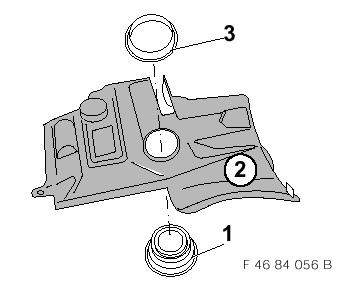
5 6. Overview of Telephone Wiring Harness Routing F B The telephone wiring harness A should be routed as illustrated along the audio or main wiring harness and secured with cable ties. Start at Point 1 (Punkt 1) when installing the telephone wiring harness. Branch A1 Branch A2 Branch A3 Branch A4 Branch A5 Branch A6 Branch A7 Branch A8 Branch A9 Branch A10 Branch A11 Branch A12 Branch A13 Branch A14 Branch A15 To retrofit connector behind heater/air conditioner operating unit To retrofit connector behind heater/air conditioner operating unit Route to fuse holder (on right on LHD, on left on RHD) To radio plug connector at front (only vehicles without on-board monitor radio) Behind function units carrier under heater/air conditioner operating unit (tied back and not used) To installation location of microphone in headliner To speaker in footwell cover, on LHD vehicles excess length of connection cable must be tied back To centre console (tied back and not required) To centre console installation location of eject box To centre console installation location of eject box To ground terminal point behind audio units carrier in luggage compartment To radio plug connector at rear (only vehicles with on-board monitor radio) To installation location of hands-free box in luggage compartment To installation location of hands-free box in luggage compartment To installation location of line compensator in luggage compartment 7. Cutting Opening in Headliner Only vehicles without sunroof F B Cut out template (1) and adhere to headliner behind interior light (2). Cut out opening (3) using a sharp knife while taking particular care that no cables are damaged. F B Insert underframe (1) in headliner and fit frame (2) in opening (3). Clip together underframe (1) and frame (2). 8. Installing Speaker F B Prepare cover (1) for speaker installation on driver's side. Mark opening (2) with compass: Dimension a = 72 mm Cut out opening (2) using compass saw and deburr with file. F B Fit speaker (1) in footwell cover (2) and firmly screw to speaker ring (3). 24
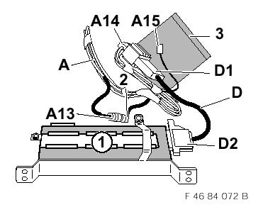
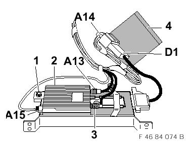
6 9. Installing Telephone Wiring Harness F B Fit telephone wiring harness A as illustrated in lefthand footwell. Start at Point 1 (Punkt 1) when installing the telephone wiring harness A. All cables and lines should be secured with cable ties. Route branches A1 and A2, 8-pin socket and pin housings under console to retrofit connector X322 behind heater/air conditioner operating unit. Route branch A3, 1-pin connection contact, to fuse plate in glovebox along heater box and main wiring loom and secure with cable ties. Route branch A4, 1-pin black pin housing with cable jumper and socket contact to 17-pin socket housing of radio plug connector. The cable is insulated and tied back on vehicles with on-board monitor radio. Branch A5, 10-pin black socket housing for keypad handset is not required and is pushed back under heater box. Route branch A6, 3-pin black socket housing, connection lead for microphone along A-pillar upward to headliner. Route connection lead under headliner to installation location of microphone and secure with textile adhesive tape to sheet metal reinforcement. Route branch A7 LHD, 3-pin yellow socket housing along main wiring loom to installation location of telephone speaker. On LHD vehicles, excess length must be tied back. Route branch A7 RHD, 3-pin yellow socket housing along main wiring loom behind heater box to installation location of telephone speaker. Route branch A8, 6-pin neutral-coloured socket housing, under carpet to opening next to handbrake lever and leave protruding by approx. 15 cm. Branch A8 is tied back and no longer required. Route branch A9, 1-pin pin housing, antenna lead under carpet to opening next to handbrake and leave protruding by approx. 15 cm. B4 of eject box will be later screwed to branch A9. Route branch A10, 18-pin black socket housing, under carpet to opening next to handbrake lever and leave protruding by approx. 15 cm. Branch A10 will be later connected to branch C2 from the interface. Route branches A11 to A15 towards the rear into luggage compartment on left along main wiring loom. 10. Connecting Telephone Wiring Harness to Vehicle Components Connecting branches A1 and A2 F B Unplug retrofit connector X322 and 8-pin plug connection (1 and 2) and connect branches A1 and A2, 8-pin black socket and pin housings, between them. Secure the new plug connections (1 and A1 as well as 2 and A2) with a cable tie. Connecting branch A3 F B Separate fuse distributor (1) as illustrated. Remove contact retainer (2). Insert branch A3 from rear into connection block at free plug-slot of fuse F39. After assembling fuse distributor (1), fit fuse 5A in fuse slot F39. Connecting branch A4 Only vehicles without on-board monitor radio Branch A4 is insulated and tied back on vehicles with on-board monitor radio. F B Open 17-pin socket housing of radio plug connector (1) and connect branch A4 as follows: Unpin existing socket contact from plug-in slot pin 4, black wire, of 17-pin socket housing of radio plug connector (1). Connect socket contact from branch A4, black wire, to 17-pin socket housing of radio plug connector in plug-in location pin 4. The enclosed plastic housing is connected to the free unpinned socket contact of the radio connection cable and plugged together with the 1-pin pin housing of branch A4, black wire. aif the 17-pin socket housing of radio plug connector (1) is not used in plug-in slot pin 4, only the socket contact of branch A4, black wire, is connected to plug-in slot pin 4. Connecting branch A11 (Illustration shows vehicle with audio units carrier in luggage compartment) F B Connect branch A11, 6 mm cable eye, to ground point X13016 with existing hexagon screw. Route branches A13, A14 and A15 to connection point of hands-free box and of line compensator on left-hand side of luggage compartment. 25
7 Connecting branch A12 Only vehicles with on-board radio Branch A12 is insulated and tied back on vehicles without on-board monitor radio. F B Open 17-pin socket housing of on-board monitor radio plug connector (1) and connect branch A12 as follows: Unpin existing socket contact from plug-in location pin 4, black wire, of 17-pin socket housing of on-board monitor radio plug connector (1). Connect socket contact from branch A12, black wire, to 17-pin socket housing of on-board monitor plug connector (1) in plug-in slot pin 4. The enclosed plastic housing is connected to the free unpinned socket contact of the on-board monitor radio connection cable and plugged together with 1-pin pin housing of branch A12, black wire. aif the 17-pin socket housing of on-board monitor radio plug connector (1) is not used in plug-in slot pin 4, then only the socket contact from branch A12, black wire, is connected to plug-in slot pin Installing Microphone for Hands-Free System bcare must be taken when installing branch A6 to make sure that the cable is fitted neatly in the cable duct in the A-pillar so as to ensure operation of the head airbag is not impaired.c Only vehicles without sunroof F B Connect branch A6, 3-pin black socket housing, from telephone wiring harness A to microphone (1). Fit microphone (1) in cover (2). bnote direction indicated by arrow on cover (2) and microphone (1).c Fit cover (2) in headliner. Only vehicles with sunroof F B Press microphone cover (1) and microphone (2) into new cover (3) (note direction indicated by arrow on microphone, arrow must point forward). Press sunroof switch (4) into cover (3). F B Connect sunroof switch (1). Connect branch A6, 3-pin black socket housing from telephone wiring harness to microphone (2). Fit cover (3) in headliner. 12. Connecting Speaker F B Connect branch A7, 3-pin yellow socket housing, from telephone wiring harness to speaker (1). atake care not to bend the connection contacts of the speaker. 13. Preparing Installation of Centre Console F B Pass plug connector B1 for mobile phone through console insert (1). Fit eject box (2) in console insert (1) taking care that the cable is not trapped. Fit cable guide (3) about spiral cable (4) as illustrated. F B bclip cable guide (1) closed such that the last bend of spiral cable (2) is not visible at the end of the cable guide.c F B afit cable guide (1) as illustrated and clip in console insert (2) such that both connection leads B2+B3 and antenna lead B4 on the right and the non-spiral section (3) of the spiral cable on the left are fitted under the retainer of cable guide (1). F B Place the non-spiral section (1) of the spiral connection lead on the left next to cable guide (2), if necessary, push back excess length under cable guide (1). Adhere sealing strip (3) as illustrated on cable guide (2). F B Fit preassembled eject box (1) in removed centre console (2) and clip in position. bmake sure the cables are not trapped.c F B Remove reinforcement (1 and 3) from centre console (4) and break at prepunched edge (2). Fit remaining reinforcement piece (3) in console (4). F B Adhere sealing strip (1) as illustrated in support bracket (2) for interface (3). Fit interface (3) in support bracket (2). Adhere sealing strip on interface (3). 26
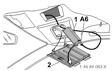
8 F B Place prepared interface (1) on removed centre console (2) and secure (clip) to support bracket (3). Connect plug connector B3, 12-pin socket housing of eject box into interface. Connect plug connector B2, 6-pin pin housing of eject box to plug connector C1, 6-pin socket housing of interface. 14. Installing Centre Console F B Connect plug connector C2, 18-pin pin housing to 18-pin socket housing A10 of telephone wiring harness A. Screw plug connector B4, 1-pin socket housing, to 1-pin pin housing A9 of antenna lead from telephone wiring harness A. badhere anti-rattle pad (1) on wiring harness such that it covers all plug connectors A10+C2 and B2 + C1) and antenna coupling (A9 and B4).c The tied-back 6-pin socket housing from the telephone wiring harness is not required. 15. Installing Hands-Free Box Vehicles with audio units carrier only F B Adhere sealing strips (1) to hands-free box (2) as illustrated. F B Slide retaining plate for line compensator (1) into hands-free box (2). Screw in hexagon screw (3) (required for subsequent assembly of line compensator). F B Fit hands-free box (1) in support bracket (2) and firmly secure with hexagon screw (3) in retainer (4). F B Connect adapter lead D with 25-pin socket housing D2 to hands-free box (1). Connect 26-pin pin housing D1 to 26-pin socket housing A14 from telephone wiring harness A. Connect tied-back 1-pin angled pin housing (2) of vehicle antenna to 1-pin socket housing A13 of antenna connection lead to centre console. badhere anti-rattle pad (3) on to wiring harness such that it covers the plug connections (A14 and D1), antenna cable coupling (2 and A13) and the 3-pin socket housing of the connection line for line compensator A15.c awhen installing the line compensator, the jobs described on Page 28, Section 17 Installing Line Compensator should be carried out before fitting the anti-rattle pad. F B Fit speed nuts (1) on audio units carrier (2). F B Slide hands-free box with support bracket into audio units carrier and secure with hexagon screws (1). Secure wiring harness with cable ties. 16. Installing Hands-Free Box Vehicles without audio units carrier only F B Adhere sealing strips (1) on hands-free box (2) as illustrated. F B Slide retaining plate for line compensator (1) into hands-free box (2). Screw in hexagon screw (3) (required for subsequent assembly of line compensator). F B Fit speed nuts (1) on support bracket (2). Place support bracket (2) on base mounting bracket (3) and secure with nuts (4) and hexagon screws (5). Fit edge guard (6). F B Retainer (1) must be bent approx. 30 upward as illustrated prior to installation. Fit hands-free box (2) in support bracket (3). Hook retainer (1) into position and firmly secure with hexagon screw (4). F B Fit speed nuts (1) on inner panel in left-hand side section. F B Connect adapter lead D with 25-pin socket housing D2 to hands-free box (1). Connect 26-pin pin housing D1 to 26-pin socket housing A14 from telephone wiring harness (1). Screw together 1-pin angled pin housing (2) of vehicle antenna with 1-pin socket housing A13 of antenna connection lead to centre console. badhere anti-rattle pad (3) onto wiring harness such that it covers the plug connections (A14 and D1), antenna cable coupling (2 and A13) and the 3-pin socket housing of line compensator connection lead.c 27
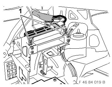
9 awhen installing the line compensator, the jobs described on Page 28, Section 17 Installing Line Compensator should be carried out before fitting the anti-rattle pad. F B Fit connected hands-free box mounted on support bracket and mounting bracket in side section as illustrated. amake sure not to damage any cables when fitting in position. F B Firmly secure basic mounting bracket (1) with hexagon screws (2). Secure telephone wiring harness (3) with cable ties (4) to basic mounting bracket (1). 17. Installing Line Compensator The illustration shows the installation of the line compensator on vehicles with an audio units carrier. The procedure for vehicles without an audio units carrier is as follows: F B Unscrew antenna lead. Unscrew hexagon screw (1). Fit line compensator (2) in position and firmly secure with hexagon screw (1). Plug branch A15, 3-pin socket housing, into line compensator (2). Screw 1-pin pin housing (3) of vehicle antenna lead to 1-pin socket housing of line compensator (2). Screw 1-pin socket housing A13 of connection cable to centre console to 1-pin pin housing on line compensator (2). badhere anti-rattle pad (4) on wiring harness such that it covers the plug connections (A14 and D1).c 18. General Information Assemble vehicle in reverse order of disassembly. Reconnect battery. Print out defect code. Carry out function test by testing the hands-free system. Mounting instructions for anti-rattle pad F B Remove protective film on adhesive strip (1) and adhere to under edge of wiring harness (2). Place anti-rattle pad (3) about wiring harness (2) including connector housing and secure with additional adhesive strip (4) on anti-rattle pad (3). Remove end adhesive strip (5) and adhere on anti-rattle pad (3). 19. Encoding This system does not require encoding. 20. Function The function of the cellular telephone is described in the "Mobile Phone" operating instructions. 21. Template for Opening in Headliner (vehicles without sunroof only) Cut out along contour Place on outer contour of interior light! 22. Schematic Circuit Diagram of Telephone Wiring Harness F B Microphone Adapter VDA Speaker Radio connection without on-board monitor radio Radio connection with on-board monitor radio Plug connection adapter lead to hands-free box Ground stereo/hifi Plug connection eject box Plug connection keypad handset Line compensator (mobile phone) 28
10 A46 Fuse distributor N27 Line compensator (mobile phone) W601 Shield open X001 Radio plug connector (with on-board monitor radio only) X002 Radio plug connector (without on-board monitor radio only) X003 Radio plug connector (without on-board monitor radio only) X322 Plug connection, HiFi X695 Plug connection, adapter lead to hands-free box X704 Connector 31 X1234 Connector RA7 X1483 Connector 30 X1744 Connector MICRO + X1745 Connector MICRO - X1765 Plug connection line compensator X1963 Speaker connection X3276 Connector tele on X4221 Plug connection, microphone X4544 Plug connection, keypad handset (not required) X4545 Plug connection, eject box X4546 Plug connection, adapter VDA (not required) X4547 Connector, ON/OFF X4548 Connector, audio GND X4549 Connector DSC UPLINK X4550 Connector DSC DOWNLINK X4551 Connector SWA + X4552 Connector, logic GND X4553 Connector, mute X4554 Connector Ext. B+ X4556 Connector, TX audio X6490 Solder connector shield (terminal 1) X6491 Solder connector shield X6493 Solder connector shield X6502 Connection adapter lead X10015 Fuse holder I A46 X13016 Ground stereo HiFi X18355 Connector, I-bus X18764 Connector, tel. NF+ X18765 Connector, tel. NF- 29
11 4. Übersicht Einbausatz Mittelkonsole B B2 B3 B C1 C2 6 F B Position Bezeichnung Menge Einsatz Konsole Eject-Box Kabelführung (zweiteilig) Interface Dichtstreifen Halter für Interface Klapperschutz (Montageanleitung siehe Seite 18, Kapitel 18 Allgemeine Hinweise) Position Bezeichnung Anschlußort im Fahzeug B1 B2 B3 B4 C1 C2 10poliges Stiftgehäuse 6poliges Stiftgehäuse 12poliges Buchsengehäuse 1poliges Buchsengehäuse 6poliges Buchsengehäuse 18poliges Stiftgehäuse Handy 6poliges Buchsengehäuse Interface (C1) 12poliges Stiftgehäuse Interface 1poliges Stiftgehäuse Antennenkabel Mittelkonsole (A9) 6poliges Stiftgehäuse Eject-Box (B2) 18poliges Buchsengehäuse Telefonkabelbaum Mittelkonsole (A10) 6
12
13
14
15 22. Stromlaufplan Telefonkabelbaum N27 LEITUNGSKOMPENSATOR (HANDY) A46 Sicherungsverteiler 31E < RAD TELE 30< BR X704 VB 31-IVE WS X3276 VB TELE EI RT X1483 VB 30 X1765 5A F39 5A 2 X RT A46 N27 W601 X001 X002 X003 X322 X695 X704 X1234 X1483 X1744 X1745 X1765 X1963 X3276 X4221 X4544 X4545 X4546 X4547 X4548 X4549 X4550 X4551 X4552 X4553 X4554 X4556 X6490 X6491 X6493 X6502 X10015 X13016 X18355 X18764 X18765 Leitungskompensator (Handy) Schirm offen Radioanschlußstecker (nur mit BM-Radio) Radioanschlußstecker (nur ohne BM-Radio) Radioanschlußstecker (nur ohne BM-Radio) STVB HIFI STVB Adapterkabel zu FSE-Box VB 31 VB RA7 VB30 VB MIKRO + VB MIKRO - STVB Leitungskompensator Anschl. Lautsprecher VB Tele ein STVB Mikrofon STVB Bedienhörer (wird nicht benötigt) STVB Eject-box STVB Adapter VDA (wird nicht benötigt) VB on/off VB Audio GND VB DSC UPLINK VB DSC DOWNLINK VB SWA + VB logic GND VB Mute VB Ext. B+ VB TX Audio Lötverbinder Schirm (Kl. 1) Lötverbinder Schirm Lötverbinder Schirm Anschluß Adapterleitung Sicherungshalter I A46 Masse Stereo HiFi VB I-Bus VB Tel. NF+ VB Tel. NF- F B 20
16 1 2 1
17 3 4 2

18

19

20

21

22
23
Teile und Zubehör - Einbauanleitung
 Teile und Zubehör - Einbauanleitung F 46 0350 2W Nachrüstkabelbaum BMW Mobiltelefon (GSM) BMW 3er-Reihe Coupé, touring und Limousine (E46/2/3/4) Die Einbauanleitung ist nur gültig für Fahrzeuge ohne (SA
Teile und Zubehör - Einbauanleitung
 Teile und Zubehör - Einbauanleitung F 36 0037 B Einbausatz Sound-Modul-System für BMW 3er Reihe (E36/7) Z3 roadster Linkslenker Die Einbauanleitung ist nur gültig für Fahrzeuge mit Stereovorbereitung beziehungsweise
Teile und Zubehör - Einbauanleitung
 Teile und Zubehör - Einbauanleitung ;;;;;; ;;;;;;;; ;;;;;;;; ;;;;;;;;; ;; ;;;;;; ;;;;;;;; ;;;;;;;;; ;;;;;;;;; ;;;;;;;;;; F 39 66 017 für BMW 5er-Reihe, touring (E39/2) Nur zum Gebrauch in der BMW HO bestimmt.
Teile und Zubehör - Einbauanleitung
 Teile und Zubehör - Einbauanleitung F 36 54 051 Überroll-Schutzsystem für BMW Z3 roadster (E36/7) mit Subwoofer - System Harman Kardon Nicht in Kombination mit starrem/klappbarem Windschutz verbaubar.
Teile und Zubehör - Einbauanleitung
 Teile und Zubehör - Einbauanleitung F 9 09 EVA Park Distance Control (PDC) vorn und hinten BMW 5er-Reihe (E 9) Nur zum Gebrauch in der BMW HO bestimmt. Einbauzeit ca. 8 Stunden, die je nach Zustand und
Parts and Accessories Installation Instructions
 Parts and Accessories Installation Instructions R 1 3 5 2 4 F 38 0213 B Basic retrofit kit for hands-free facility for upgrading various mobile phones BMW 7 Series (E38) LHD without telephone preparation
Teile und Zubehör - Einbauanleitung
 Teile und Zubehör - Einbauanleitung F 9 52 000 M Sitzheizung vorne, BMW 5er Reihe (E9) ab 9/98 Fachkenntnisse sind Voraussetzung. BMW Parts and Accessories Installation Instruction Seat heater, front,
Teile und Zubehör - Einbauanleitung
 Teile und Zubehör - Einbauanleitung F 39 0001 2W Standheizung BMW 5er-Reihe (E 39) Linkslenker mit M57 Motor (Diesel) Fachkenntnisse sind Voraussetzung. Einbauzeit ca. 3 (touring 3,5) Stunden, die je nach
Teile und Zubehör - Einbauanleitung
 Teile und Zubehör - Einbauanleitung F 46 0033 2W Diebstahlwarnanlage (DWA) für BMW 3er-Reihe (E 46/2/4) Linkslenker mit Funkfernbedienung ab Band (Nur zum Gebrauch in der BMW HO bestimmt.) Einbauzeit ca.
Teile und Zubehör - Einbauanleitung
 Teile und Zubehör - Einbauanleitung F 36 82 1040 Windschutz klappbare Ausführung Nicht in Kombination mit Überroll-Schutzsystem verbaubar. BMW Z3 roadster (E36/7) Der Einbau des Windschutzes sollte von
Parts and Accessories Installation Instructions
 Parts and Accessories Installation Instructions Installation kit, sound module MINI (R5) Cooper S (R53) Left-hand drive (LHD) Not suitable for vehicles with option SA 69 (navigation system with on-board
Parts and Accessories. Installation Instructions.
 Parts and Accessories. Installation Instructions. Universal charger/hands-free kit retrofit BMW 3 Series Saloon (E 90) These installation instructions are only valid for cars with SA 606 (Business navigation
BMW Parts and Accessories Installation Instructions
 BMW Parts and Accessories Installation Instructions 46 77 B BMW subwoofer module retrofit kit BMW 3 Series compact (E 46/5) LHD Technical and electrical knowledge required Installation time approx. 1.5-2.5
Teile und Zubehör - Einbauanleitung
 Teile und Zubehör - Einbauanleitung 0 0 0 I - TONE + RDS TP TAPE MS BMW 1 2 3 4 5 6 AM FM AUTO _ + A-TEMP C/ F UHR MEMO SET h/dat min/dat HAUPTMENÜ ZIELEINGABE ZIELFÜHRUNG STAND-BY EINSTELLUNGEN ASC R
BMW Parts and Accessories Installation Instructions
 1 4 BMW Parts and Accessories Installation Instructions INFO 2 5 3 6 TONE SELET FM AM MODE MENU F 38 0393 B Retrofit Kit Onboard Monitor and Navigation System BMW 7 Series (E38) The installation instructions
Parts and AccessoriesInstallation Instructions
 MOTOROLA Parts and AccessoriesInstallation Instructions 36 9 Z Retrofit hands-free kit for Motorola mobile phones Series V5 / V369 / V3688 BMW Z3 (E 36/7) roadster and coupé The installation time is approx.
Original BMW Accessories. Installation Instructions.
 Questo file è stato scaricato da www.bmwretrofit.it @: info@bmwretrofit.it Postmontaggi - codifiche - ricambi - a Cesena Original BMW Accessories. Installation Instructions. TV function retrofit, only
Teile und Zubehör - Einbauanleitung
 Teile und Zubehör - inbauanleitung s2 s2 Original MW Zubehör-Seitenschweller MW 3er-Reihe Limousine ( 46/4) achkenntnisse sind Voraussetzung. MW Parts and ccessories Installation Instruction Original MW
SCdefault. 900 Installation instructions
 SCdefault 900 Installation instructions SITdefault Airbag replacement harness MONTERINGSANVISNING INSTALLATION INSTRUCTIONS MONTAGEANLEITUNG INSTRUCTIONS DE MONTAGE Accessories Part No. Group Date Instruction
Teile und Zubehör - Einbauanleitung
 Teile und Zubehör - inbauanleitung s2 M MT 2532 Original MW Zubehör-Heckschürze MW 3er-Reihe Limousine ( 46/4) Fachkenntnisse sind Voraussetzung. MW Parts and ccessories Installation Instruction Original
Teile und Zubehör Einbauanleitung
 Teile und Zubehör Einbauanleitung Nachrüstung Scheinwerfer Facelift für BMW 5er-Reihe Limousine, touring (E 39, E 39/) bis 9/00 Retrofit Headlights Facelift for BMW 5 Series saloon, touring (E39, E39/)
Teile und Zubehör - Einbauanleitung
 Teile und Zubehör - Einbauanleitung F 38 0027 EVA BMW Parts and Accessories Installation Instruction Park Distance Control (PDC), rear BMW 7 Series (E38) Best.-Nr. 01 29 0 000 791 XII/98 Printed in Germany
Parts and Accessories. Installation instructions.
 Parts and Accessories. Installation instructions. Retrofit Kit - Bi-Xenon Headlight BMW 5 Series Saloon (E 60) Installation instructions valid only for vehicles with SA 502 (headlight washer system) and
Parts and Accessories Installation Instructions
 Parts and Accessories Installation Instructions F 53 7 W Retrofit auxiliary heating system BMW X5 (E 53) with M57 engine (diesel) The installation time is approx..5-4.5 hours (see important information),
Parts and Accessories. Installation Instructions.
 Parts and Accessories. Installation Instructions. Park Distance Control (PDC) retrofit kit BMW X5 (E 5) Retrofit kit No. 66 0 0 007 0 66 0 0 4 68 66 0 0 09 685 66 0 0 9 509 Installation time The installation
Original BMW Accessories. Installation Instructions.
 Original BMW Accessories. Installation Instructions. Anti-Theft Alarm System Retrofit BMW 3 Series Saloon (E90) BMW 3 Series Coupé (E92) Retrofit kit no.: 65 2 0 399 635 Anti-theft alarm system retrofit
900 Installation instructions. SCdefault
 SCdefault 900 Installation instructions SITdefault Parking assistance (SPA) MONTERINGSANVISNING INSTALLATION INSTRUCTIONS MONTAGEANLEITUNG INSTRUCTIONS DE MONTAGE Accessories Part No. Group Date Instruction
Parts and Accessories Installation Instructions
 Parts and Accessories Installation Instructions Park Distance Control (PDC) Rear Retrofit BMW Z4 (E 85) The installation time is approx. 4 hours, but this may vary depending on the condition of the car
Parts and Accessories Installation Instructions
 Parts and Accessories Installation Instructions F 46 3 EVA Headlight Cleaning System (SRA) BMW 3 Series (E 46) The installation time is approx. 3.5 hours, but this may vary depending on the condition of
Teile und Zubehör - Einbauanleitung
 Teile und Zubehör - Einbauanleitung Heckstützen für den BMW Multi-Trailer BMW Parts and Accessories Installation Instruction Rear supports for the BMW Multi-Trailer Instructions de montage des pièces et
 INSTALLATION INSTRUCTIONS Accessory ACCESSORY HANDSFREELINK Application 2010 CR-V Publications No. AII 42587 Issue Date AUG 2009 PARTS LIST HFL Attachment Kit P/N 08E02-SWA-130 (Ivory) P/N 08E02-SWA-170
Parts and Accessories Installation Instructions
 7 Parts and Accessories Installation Instructions 3 4 5 6 8 MINI R5 84 Z On-board computer retrofit kit MINI (R 5) The installation time is approx. hours, but this may vary depending on the condition of
Parts and Accessories Installation Instructions
 Parts and Accessories Installation Instructions 46 96 V Universal remote control in the interior rear-view mirror retrofit kit BMW 3 Series (E 46), BMW 5 Series (E 39), BMW 7 Series (E 38) The installation
Teile und Zubehör - Einbauanleitung
 Teile und Zubehör - Einbauanleitung BMW Nachrüstsatz BMW Spracheingabesystem seriengleiche Nachrüstung BMW 3er-Reihe Coupé und Limousine (E46/2/4) Nur für Fahrzeuge mit SA 640 und Spracheingabetaste am
Teile und Zubehör - Einbauanleitung
 Teile und Zubehör - Einbauanleitung F 8 0007 EVA BMW Parts and Accessories Installation Instruction Park Distance Control (PDC), front and rear BMW 7 Series (E8) Best.-Nr. 09 0 000 79 II/99 Printed in
Parts and Accessories. Installation Instructions.
 Parts and Accessories. Installation Instructions. Retrofit alarm system BMW 5 Series (E 60) Retrofit kit No. 65 73 0 304 463 Installation time The installation time is approx 5.0-5.5 hours, but this may
Original BMW Accessories. Installation Instructions.
 Original BMW Accessories. Installation Instructions. M Performance Alcantara Steering Wheel II with Race Display Retrofit BMW Series (F0/F) BMW Series (F/F3) BMW 3 Series (F30/F3/F34/F35) BMW 4 Series
Parts and Accessories Installation Instructions
 Parts and Accessories Installation Instructions 5 224 B Installation Kit Headlight Cleaning System Mini (R5/R53) LHD and RHD Installation time approx. 1.5-2 hours, which can vary according to the condition
393: Multimedia system for the rear seat Multimedia system for the rear seat
 393: Multimedia system for the rear seat S80 (07-), 2008, B8444S, TF-80SC AWD, L.H.D, YV1AH852881073834, 073834 4/1/2013 PRINT 393: Multimedia system for the rear seat Multimedia system for the rear seat
Saab 900 M94-98, Saab 9-3, Saab 9000, Saab 9-5
 SCdefault 900 Monteringsanvisning SITdefault MONTERINGSANVISNING INSTALLATION INSTRUCTIONS MONTAGEANLEITUNG INSTALLATIONS DE MONTAGE Branch cable set LHD Accessories Part No. Group Date Instruction Part
Original BMW Accessory. Installation Instructions.
 Original MW ccessory. Installation Instructions. Xenon light retrofit with automatic headlight adjustment control MW 3 Series Saloon (E 90) MW 3 Series Touring (E 9) Retrofit kit No. 63 3 0 395 396 63
Original BMW Accessories. Installation Instructions.
 Original BMW ccessories. Installation Instructions. Trailer tow hitch retrofit (removable version) BMW X5 (E70) BMW X6 (E7) Retrofit kit No. 7 60 2 55 44 Electrical components retrofit kit (for E70 only)
394: Handsfree, Bluetooth Handsfree, Bluetooth
 394: Handsfree, Bluetooth S80 (07-), 2008, B8444S, TF-80SC AWD, L.H.D, YV1AH852881073834, 073834 4/1/2013 PRINT 394: Handsfree, Bluetooth Handsfree, Bluetooth Installation instruction: 31310098 INTRODUCTION
Removing and installing moulded headliner
 Page 1 of 13 Removing and installing moulded headliner Special tools and workshop equipment required Removal lever -80-200- Front-end hook -3370- Removal wedge -3409- Removing Remove driver's seat: Audi
TOYOTA CAMRY HANDS FREE BLU LOGIC Preparation
 TOYOTA CAMRY 2008- HANDS FREE BLU LOGIC Preparation Part #: PT923-00111 Conflicts: JBL Audio, Factory Navigation NOTE: Part number of this accessory may not be the same as the part number shown. Kit Contents:
Original BMW Accessories. Installation Instructions.
 Original BMW Accessories. Installation Instructions. BMW Integrated Navigation. BMW Series (F20, F2) BMW 2 Series (F22, F23, F45, F46) BMW 3 Series (F30, F3, F34, F35) BMW 4 Series (F32, F33, F36) BMW
Original BMW Accessories. Installation Instructions.
 Original BMW Accessories. Installation Instructions. Bi-xenon light with ALC BMW Series (E 8, E 82, E 87 LCI) These installation instructions are valid only for cars with SA 502 (headlight washer system)
PRELIMINARY INSTALLATION INSTRUCTIONS. PARTS LIST Attachment Kit(sold separately): P/N 08B23-S9V-100B. Display bracket.
: P/N 08B23-S9V-100B. Display bracket.") INSTALLATION INSTRUCTIONS Accessory Application Publications No. in- ENTERTAINMENT SYSTEM 2006 PILOT All 30502 Issue Date SEP 2005 PARTS LIST Attachment Kit(sold separately): P/N 08B23-S9V-100B Display
INSTALLATION INSTRUCTIONS Accessory Application Publications No. in- ENTERTAINMENT SYSTEM 2006 PILOT All 30502 Issue Date SEP 2005 PARTS LIST Attachment Kit(sold separately): P/N 08B23-S9V-100B Display
Parts and Accessories Installation Instructions
 SHIFT DEL Parts and Accessories Installation Instructions MENU 1 2 3 ABC DEF GHI PQRS 5 JKL 5 TUV 6 MNO 6 WXY 6 73 B Electronic Logbook BMW 3 Series Saloon (E 6/) LHD BMW 3 Series Touring (E 6/3) LHD BMW
INSTALLATION INSTRUCTIONS
 Rear Vision System Mirror Display Dodge Ram Kit Contents: Instruction Sheets Template Chassis Harness Endgate Handle with Camera Wire Ties (Qty: 17) Bottle of ZTech Plug for Non-Locking Endgates (Optional)
TOYOTA VENZA HANDS FREE BLU LOGIC Preparation
 TOYOTA VENZA 2009- HANDS FREE BLU LOGIC Preparation Part #: PT923-00111 Conflicts: JBL Audio NOTE: Part number of this accessory may not be the same as the part number shown. Kit Contents: For kits manufactured
2006 MINI Cooper ACCESSORIES & EQUIPMENT Audio, Navigation & Anti-Theft Systems - Repair Instructions - Cooper (1.6L) R50/W10 & Cooper S
 R50/W10 & Cooper S") Fig. 1: Locating Radio Receiver Retaining Screws 2006 MINI Cooper 2002-05 ACCESSORIES & EQUIPMENT Audio, Navigation & Anti-Theft Systems - Repair Instructions - Cooper (1.6L) R50/W10 & Cooper S MONO RADIO
Fig. 1: Locating Radio Receiver Retaining Screws 2006 MINI Cooper 2002-05 ACCESSORIES & EQUIPMENT Audio, Navigation & Anti-Theft Systems - Repair Instructions - Cooper (1.6L) R50/W10 & Cooper S MONO RADIO
Saab 9-3 4D/5D M page 3 Saab 9-5 M page 17
 SCdefault 900 Monteringsanvisning SITdefault MONTERINGSNVISNING INSTLLTION INSTRUCTIONS MONTGENLEITUNG INSTRUCTIONS DE MONTGE Saab 9-3 4D/5D M03-............................... page 3...................................
Original BMW Accessories. Installation Instructions.
 Original BMW Accessories. Installation Instructions. Removable trailer tow hitch retrofit BMW 3 Series Saloon (F30) BMW 3 Series Touring (F3) BMW 4 Series Coupé (F32) BMW 4 Series Gran Coupé (F36) These
INSTALLATION INSTRUCTIONS
 INSTALLATION INSTRUCTIONS Accessory Application Publications No. in- ENTERTAINMENT SYSTEM 2004 TSX BII 24811 Issue Date APRIL 2003 PARTS LIST Attachment Kit P/N 08B23-SDA-101A Monitor bracket harness FM
ROOF HEADLINING ASSY EXTERIOR/INTERIOR TRIM 760VC 02 REPLACEMENT
 REPLACEMENT 7627 The installation is in the reverse order of the removal. However, when there is a special point concerning the installation, it is indicated. On the LH side, use the same procedures as
TOYOTA HIGHLANDE R REARSIGHT Part Number: Code: MC90 KIT CONTENTS ADDITIONAL ITEMS REQUIRED FOR INSTALL RECOMMENDED TOOLS
 TOYOTA HIGHLANDE R 2009- REARSIGHT Part Number: 00016-00085 Code: MC90 KIT CONTENTS ITEM QTY DESCRIPTION 1 1 MIRROR/MONITOR 2 1 REAR CAMERA ASSEMBLY 3 1 CAMERA EXTENSION HARNESS 4 1 SACK PARTS 5 1 OWNER
SCION xb AUTO-DIMMING MIRROR Preparation
 Preparation Part Number: PT374-02090 Kit Contents Item # Quantity Reqd. Description 1 1 AD Mirror Assembly w/ PRNDL 2 1 Hardware bag Hardware Bag Contents Item # Quantity Reqd. Description 1 2 T-tap Connectors,
Parts and Accessories Installation Instructions
 Parts and Accessories Installation Instructions 46 292 Z Facelift tail lights retrofit kit BMW 3 Series Saloon (E46/4) LHD and RHD Models up to 9/2 Installation time: approx. 2.5 hours The installation
Installation instructions, accessories - Rear Seat Entertainment
 XC90 Section Group Weight(Kg/Pounds) Year Month 3 39 2004 10 XC90 2003, XC90 2004, XC90 2005, XC90 2006, XC90 2007, XC90 2008 Replaces issue: 2003 12 J3904620 Page 1 of 18 Required tools A0000162 A0000163
Please read thoroughly before starting installation and check that kit contents are complete.
 Rear Vision System Mirror Display 2013-Current Ram (Kit part number 1009-9518) Please read thoroughly before starting installation and check that kit contents are complete. Items Included in the Kit: Rear
TOYOTA tc HANDS FREE BLU LOGIC Preparation
 TOYOTA tc 2011- HANDS FREE BLU LOGIC Preparation Part #: PT923-00111 Conflicts: JBL Audio, Factory Navigation NOTE: Part number of this accessory may not be the same as the part number shown. Kit Contents:
General Applicability Note: Recommended Tools. Personal & Vehicle Protection Safety Goggles Seat Covers Floor Covers Special Tools. Installation Tools
 TOYOTA HIGHLANDER/HIGHLANDER HV 2008- Preparation Part #: PT923-00111 Conflicts: JBL Audio, Factory Navigation NOTE: Part number of this accessory may not be the same as the part number shown. Kit Contents:
INSTALLATION INSTRUCTIONS
 INSTALLATION INSTRUCTIONS Accessory NIGHT Application CR-V Publications No. AII 32951 Issue Date SEP 2006 PARTS LIST Automatic Day/Night Mirror Attachment Kit P/N 08V03-SWA-100 Harness cover set Automatic
Parts and Accessories Installation Instructions
 Parts and Accessories Installation Instructions 0 40 00 60 80 80 60 00 40 0 0 40 0 3 4 5 7 6 R/T 046 0455 Z Multi-functional steering wheel (MFL) retrofit kit Cruise control (GRA) Retrofit kit for BMW
Installation instructions, accessories RTI S80
 Installation instructions, accessories Instruction No 8685714 Version 1.0 5 Part. No. RTI S80 Volvo Car Corporation RTI S80-8685714 - V1.0 Page 1 / 25 Equipment A0000161 A0000162 A0801178 D8802049 Page
TOYOTA TACOMA HANDS FREE BLU LOGIC Preparation. Item 5 Item 6 Item 7 Item 8. Item 4. General Applicability Note: Recommended Tools
 TOYOTA TACOMA 2008- HANDS FREE BLU LOGIC Preparation Part #: PT923-00098 Conflicts: JBL Audio, Factory Navigation Kit Contents: NOTE: Part number of this accessory may not be the same as the part number
SCION xb EC REARVIEW MIRROR Preparation
 Preparation Part Number: PT374-02090 Kit Contents Item # Quantity Reqd. Description 1 1 AD Mirror Assembly w/ PRNDL 2 1 Hardware bag Hardware Bag Contents Item # Quantity Reqd. Description 1 2 T-tap Connectors,
Conflicts TOYOTA TACOMA HANDS FREE BLU TOOTH. Part Number: Accessory Code: BT4 ADDITIONAL ITEMS REQUIRED FOR INSTALL
 TOYOTA TACOMA 2011 - HANDS FREE BLU TOOTH Part Number: 00016-00401 Accessory Code: BT4 Conflicts Factory Bluetooth System & JBL Audio KIT CONTENTS ITEM QTY DESCRIPTION 1 1 INTERFACE MODULE 2 1 INTERFACE
GENUINE PARTS INSTALLATION INSTRUCTIONS
 GENUINE PARTS INSTALLATION INSTRUCTIONS 1. 2. 3. 4. DESCRIPTION: Accent light Kit APPLICATION: Infiniti JX (2013) PART NUMBER: 999F3 YY000 - Universal Accent Lighting Kit. KIT CONTENTS: Item QTY Description
Parts and Accessories Installation Instructions
 Parts and Accessories Installation Instructions 5 224 B Retrofit Kit Xenon Headlights MINI (R 5/R 53) LHD and RHD The installation time is approx. 8 hours, but this may vary depending on the condition
Installation instructions, accessories - Volvo Navigation System, widescreen
 S60 Section Group Weight(Kg/Pounds) Year Month 3 39 2001 04 S60 2001, S60 2002 Page 1 of 21 Page 2 of 21 Required tools A0000162 A0000161 A0801178 M8802509 M3903563 Page 3 of 21 M3903565 M8503983 Page
INSTALLATION INSTRUCTIONS
 INSTALLATION INSTRUCTIONS Accessory NIGHT Application 2007 CR-V Publications No. Issue Date SEP. 2006 PARTS LIST Automatic Day/Night Mirror Attachment Kit P/N 08V03-SWA-300 Harness cover set Automatic
INSTALLATION INSTRUCTIONS
 INSTALLATION INSTRUCTIONS Accessory Application Publications No. AII 26320 ATTACHMENT KIT 2004 S2000 Issue Date OCT 2003 PARTS LIST CD Changer Attachment Kit: P/N 08B26-S2A-100A Plain washer Template CD
Installation instructions
 Service Installation instructions Audi A4/A5 (B8 series) 2008 Engine sound system For scope of delivery 8T0.071.901* Audi Genuine Accessories Service Department. Technical Information Service Contents
 INSTALLATION INSTRUCTIONS Accessory Application 2010 CR-V Publications No. AII 42592 Issue Date AUG 2009 PARTS LIST Bass Works Attachment kit (sold separately) P/N 08B54-SWA-100 Bass system harness 4 Washer-bolts,
Conflicts. TOYOTA 4Runner REARSIGHT. Part Number: Code: MC90 KIT CONTENTS ADDITIONAL ITEMS REQUIRED FOR INSTALL RECOMMENDED TOOLS
 TOYOTA 4Runner 2010 - REARSIGHT Part Number: 00016-00085 Code: MC90 Conflicts KIT CONTENTS ITEM QTY DESCRIPTION 1 1 MIRROR/MONITOR 2 1 REAR CAMERA ASSEMBLY 3 1 CAMERA EXTENSION HARNESS 4 1 SACK PARTS 5
INSTALLATION INSTRUCTIONS
 INSTALLATION INSTRUCTIONS Accessory Application Publications No. AII 38137-38714 Accessory HandsFreeLink 2008 ODYSSEY Issue Date JAN 2008 PARTS LIST Attachment Kit P/N 08E02-SHJ-100B trim Fuse label Fuse
INSTALLATION INSTRUCTIONS
 INSTALLATION INSTRUCTIONS Accessory Application Publications No. AII 33373 ATTACHMENT KIT (TRUNK MOUNT) 2007 S2000 Issue Date AUG 2006 PARTS LIST Plain washer CD Changer Attachment Kit: P/N 08B26-S2A-100A
Installation instructions, accessories. Multimedia monitor with DVD, Dual screen. Multimedia monitor with DVD, Dual screen V1.
 Installation instructions, accessories Instruction No 30756560 Version 1.2 5 Part. No. 30756177 Multimedia monitor with DVD, Dual screen Volvo Car Corporation Multimedia monitor with DVD, Dual screen-
Installation instructions, accessories - Bluetooth, Mute kit XC / Volvo Car Corporation Göteborg, Sweden
 XC90 Section Group Weight(Kg/Pounds) Year Month 3 393 0.5/1.1 2006 11 XC90 2003, XC90 2004, XC90 2005, XC90 2006, XC90 2007, XC90 2008, XC90 2009, XC90 2010 Page 1 of 15 Required tools A0000162 IMG-242205
Saab 9-5 5D. 900 Monteringsanvisning MONTERINGSANVISNING INSTALLATION INSTRUCTIONS MONTAGEANLEITUNG INSTRUCTIONS DE MONTAGE.
 SCdefault 900 Monteringsanvisning SITdefault 12 V socket in luggage compartment MONTERINGSANVISNING INSTALLATION INSTRUCTIONS MONTAGEANLEITUNG INSTRUCTIONS DE MONTAGE Accessories Part No. Group Date Instruction
REMOVAL IR 11. Slide the inner rear view mirror.
 11 Slide REMOVAL CAUTION: Some of these service operations affect the SRS airbag system. Read the precautionary notices concerning the SRS airbag system before servicing (See page RS-1). 1. DISCONNECT
GENUINE PARTS INSTALLATION INSTRUCTIONS
 GENUINE PARTS INSTALLATION INSTRUCTIONS 1. 2. 3. DESCRIPTION: APPLICATION: PART NUMBER: Accent light Kit Cube (MY2013+) 999F3 AW000 - Universal Accent Lighting Kit. 4. KIT CONTENTS: Item QTY Description
TOYOTA Yaris Hatchback EC REARVIEW MIRROR Preparation
 Preparation Part Number: PT374-02090 Kit Contents Item # Quantity Reqd. Description 1 1 Auto Dimming Mirror Assembly w/ shift area light 2 1 Hardware bag Hardware Bag Contents Item # Quantity Reqd. Description
INSTALLATION INSTRUCTIONS
 INSTALLATION INSTRUCTIONS Accessory Application Publications No. XM SATELLITE RADIO SYSTEM (EX) 2008 PILOT All 37110 Issue Date JUN 2007 PARTS LIST XM Radio Attachment (sold separately) P/N 08B15-S9V-100A
SCION XB HANDS FREE BLU LOGIC Preparation
 SCION XB 2008- HANDS FREE BLU LOGIC Preparation Part #: PT923-00111 Conflicts: JBL Audio NOTE: Part number of this accessory may not be the same as the part number shown. Kit Contents: For kits manufactured
INSTALLATION INSTRUCTIONS
 INSTALLATION INSTRUCTIONS Accessory Accessory Hands Free Link Application 2008 ACCORD 2 AND 4-DOOR Publications No. AII 38281 Issue Date NOV 2007 PARTS LIST Attachment Kit P/N 08E02-TA0-100 trim retainer
GENUINE PARTS INSTALLATION INSTRUCTIONS
 GENUINE PARTS INSTALLATION INSTRUCTIONS 1. 2. 3. 4. DESCRIPTION: APPLICATION: PART NUMBER: KIT CONTENTS: Accent light Kit Versa Note 999F3 4Z000 - Accent Lighting Kit. 999Q9 AY000 - Accessory Service Connector
INSTALLATION INSTRUCTIONS
 INSTALLATION INSTRUCTIONS Accessory Application Publications No. AII 37978 XM RADIO SYSTEM 2008 CIVIC HYBRID Issue Date SEP 2007 PARTS LIST XM Radio Attachment (sold separately): P/N 08B15-SNA-100B 7 Wire
TOYOTA TUNDRA HANDS FREE BLU LOGIC Preparation
 TOYOTA TUNDRA 2008- HANDS FREE BLU LOGIC Preparation Part #: PT923-00111 Conflicts: JBL Audio NOTE: Part number of this accessory may not be the same as the part number shown. Kit Contents: For kits manufactured
Conflicts: JBL Audio, Factory Navigation, Accessory XM Satellite Radio, and Accessory Sirius Satellite Radio
 TOYOTA YARIS SEDAN 2008- HANDS FREE BLU LOGIC Preparation Part #: PT923-00111 NOTE: Part number of this accessory may not be the same as the part number shown. Conflicts: JBL Audio, Factory Navigation,
Parts and Accessories Installation Instructions
 Parts and Accessories Installation Instructions TV function retrofit kit BMW X5 Series ( 53) These installation instructions are only valid for cars with SA 69 (navigation system) Important information
INSTALLATION INSTRUCTIONS
 INSTALLATION INSTRUCTIONS Accessory Application Publications No. AII 26042-26353 XM INTERFACE ODYSSEY EXCEPT EX-L WITH NAVI/RES Issue Date FEB 2004 PARTS LIST 8 Wire ties XM Radio Attachment P/N 08B15-S0X-100
REARSIGHT PART NUMBER: Code: MC1 RECOMMENDED SEQUENCE OF APPLICATION
 Document # 3848 REVISION A 1/26/06 2006 TOYOTA TACOMA REARSIGHT PART NUMBER: 00016-00050 Code: MC1 RE V I S I O N A KIT CONTENTS ITEM QTY DESCRIPTION 1 1 MIRROR/MONITOR 2 1 REAR CAMERA ASSEMBLY 3 1 CAMERA
Original BMW Accessories. Installation Instructions.
 Original BMW Accessories. Installation Instructions. LCI Retrofit BMW 5 Series Touring (E61) BMW 5 Series Saloon (E60) Installation instructions only valid for cars with SA 522 (BiXenon) or SA 524 (AHL).
Front seats. j a t CAUTION! Before beginning repairs on the electrical system: Obtain the anti-theft radio security code. Switch the ignition off.
 j a t Front seats 72-1 CAUTION! Before beginning repairs on the electrical system: Obtain the anti-theft radio security code. Switch the ignition off. Search Advanced Search Disconnect the battery Ground
Installation manual: Parrot MKi + Parrot CK3100 range C4 PICASSO C4 PICASSO
 Installation manual: Parrot MKi + Parrot CK3100 range C4 PICASSO C4 PICASSO This The brand sheet name is designed CITROËN to help C4 PICASSO you with and the the installation CITROËN logo of a are Parrot
INSTALLATION INSTRUCTIONS
 INSTALLATION INSTRUCTIONS Accessory Application Publications No. SYSTEM S2000 AII 26324 Issue Date OCT 2004 PARTS LIST Headrest Speaker System P/N 08A54-S2A-100 3 Small wire ties 2 Headrest speakers 9
Installation instructions, accessories. Handsfree, Bluetooth
 Installation instructions, accessories Instruction No 31310097 Version 1.3 5 Part. No. 31285547 Handsfree, Bluetooth Volvo Car Corporation Handsfree, Bluetooth- 31310097 - V1.3 Page 1 / 28 Equipment A0000162