Low Voltage Alternators - 4 pole LSA 52.3
|
|
|
- Ilene Lee
- 6 years ago
- Views:
Transcription
1
2 This manual concerns the alternator which you have just purchased. We wish to draw your attention to the contents of this maintenance manual. SAFETY MEASURES Before using your machine for the first time, it is important to read the whole of this installation and maintenance manual. All necessary operations and interventions on this machine must be performed by a qualified technician. Our technical support service will be pleased to provide any additional information you may require. The various operations described in this manual are accompanied by recommendations or symbols to alert the user to the potential risk of accidents. It is vital that you understand and take notice of the different warning symbols used. WARNING Warning symbol for an operation capable of damaging or destroying the machine or surrounding equipment. a) During operation, do not allow anyone to stand in front of the air outlet guards, in case anything is ejected from them. b) Do not allow children younger than 14 to go near the air outlet guards. A set of self-adhesive stickers depicting the various warning symbols is included with this maintenance manual. They should be positioned as shown in the drawing below once the machine has been fully installed. WARNING The alternators must not be put into service until the machines in which they are to be incorporated have been declared compliant with Directives EC and plus any other directives that may be applicable. This manual is be given to the end user. The range of electric alternators and their derivatives, manufactured by us or on our behalf, comply with the technical requirements of the customs Union directives (EAC). Warning symbol for general danger to personnel. Warning symbol for electrical danger to personnel. WARNING SYMBOLS We wish to draw your attention to the following 2 safety measures which must be complied with: - We reserve the right to modify the characteristics of its products at any time in order to incorporate the latest technological developments. The information contained in this document may therefore be changed without notice. This document may not be reproduced in any form without prior authorization. All brands and models have been registered and patents applied for. 2
3 CONTENTS 1 - RECEIPT Standards and safety measures Inspection Identification Storage Applications Usage restrictions TECHNICAL CHARACTERISTICS Electrical characteristics Mechanical characteristics INSTALLATION Assembly Checks prior to first use Terminal connection diagrams Commissioning Setting up SERVICING - MAINTENANCE Safety measures Routine maintenance Bearings Mechanical defects Electrical faults Dismantling, reassembly Installation & maintenance of the PMG Table of characteristics SPARE PARTS First maintenance parts Technical support service Accessories Exploded views, parts list and tightening torque Disposal and recycling instructions EC declaration of incorporation 3
 and after a visual check, turn the machine by hand to detect any malfunction. 1.")
4 1 - RECEIPT Standards and safety measures Our alternators comply with most international standards. See the EC Declaration of Incorporation on the last page Inspection On receipt of your alternator, check that it has not suffered any damage in transit. If there are obvious signs of knocks, contact the transporter (you may be able to claim on their insurance) and after a visual check, turn the machine by hand to detect any malfunction Identification The alternator is identified by means of a nameplate fixed on the machine (see drawing). Make sure that the nameplate on the machine conforms to your order. So that you can identify your alternator quickly and accurately, we suggest you fill in its specifications on the nameplate below Storage Prior to commissioning, machines should be stored : - away from humidity (< 90%); after a long period of storage, check the machine insulation. To prevent the bearings from becoming marked, do not store in an environment with significant vibration Application These alternators are mainly designed to produce electricity in the context of applications involving the use of generators Usage restrictions Use of the machine is restricted to operating conditions (environment, speed, voltage, power, etc) compatible with the characteristics indicated on the nameplate. 4
5 2 - TECHNICAL CHARACTERISTICS Electrical characteristics This alternator is a machine without sliprings or revolving field brushes, wound as 2/3 pitch ; 6 wire, with class H insulation and a field excitation system available in either AREP or PMG version (see diagrams and AVR maintenance manual). Options - Stator temperature detection sensors - Bearing sensors - Space heaters - Protection or measurement current transformer (C.T.) In order to conform to standard EN , EN , EN 55011, the R 791 interference suppression kit is needed Mechanical characteristics - Steel frame - Cast iron end shields - Single bearing standard alternator: regreasable roller bearing - Double bearing standard alternator: regreasable NDE roller bearing and DE ball bearing - Single and double bearing marine alternator or insulated bearing: regreasable NDE ball bearing - Mounting arrangement: single-bearing with feet and SAE flanges/coupling discs, double bearing with SAE flange and standard cylindrical shaft extension - Drip-proof machine, self-cooled - Degree of protection: IP 23 Options - Protection against harsh environments - Air inlet and outlet filter: IP 44 To prevent excessive temperature rise caused by clogged filters, it is advisable to monitor the stator winding with thermal sensors (PT100). AREP+PMI system with D510C (or option R449) Exciter Armature Field MAIN FIELD Surge suppressor Aux. windings STATOR : 6 wires (marked T1 to T6) T1 T2 T3 T4 T5 T6 D510C Voltage reference PMG system with D510C (or option R449) Exciter Armature Field MAIN MAIN FIELD Surge Surge suppressor suppressor Aux. windings PMG STATOR : 6 : 6 wires (marked T1 T1 to to T T6) T1 T2 T3 T4 T5 T6 T6 D510C Voltage reference 5
6 3 - INSTALLATION Personnel undertaking the various operations indicated in this section must wear personal protective equipment appropriate for mechanical and electrical hazards Assembly All mechanical handling operations must be undertaken using suitable equipment and the machine must be horizontal. Check how much the machine weighs before choosing the lifting tool. During this operation, do not allow anyone to stand under the load. Handling The generously-sized lifting eyes are for handling the alternator only. They must not be used to lift the genset. The choice of lifting hooks or handles should be determined by the shape of the lifting eyes. Choose a lifting system which respects the integrity and the environment of the machine. During this operation, do not allow anyone to stand under the load. Single-bearing coupling Before coupling, check the compatibility between the alternator and the engine by performing: - undertaking a torsional analysis of the transmission (alternators data are available on request), - checking the dimensions of the flywheel and its housing, the flange, coupling discs and offset. WARNING When coupling the alternator to the prime mover, do not use the fan to turn the alternator or rotor. The holes of the coupling discs should be aligned with the flywheel holes by cranking the engine. Make sure the machine is securely bedded in position during coupling. Check that there is lateral play on the crankshaft. Double-bearing coupling - Semi-flexible coupling Careful alignment of the machines is recommended, checking that the lack of concentricity and parallelism of both parts of the coupling do not exceed 0.1 mm. This alternator has been balanced with a 1/2 key. Location The room where the alternator is placed must be ventilated to ensure that the ambient temperature cannot exceed the data on the nameplate Checks prior to first use Electrical checks Under no circumstances should an alternator, new or otherwise, be operated if the insulation is less than 1 megohm for the stator and 100,000 ohms for the other windings. 6
7 There are 2 possible methods for restoring the above minimum values. a) Dry out the machine for 24 hours in a drying oven at a temperature of 110 C (without the regulator). b) Blow hot air into the air intake, having made sure that the machine is rotating with the exciter field disconnected. Note : Prolonged standstill In order to avoid these problems, we recommend the use of space heaters, as well as turning over the machine from time to time. Space heaters are only really effective if they are working continuously while the machine is stopped. WARNING Ensure that the alternator has the degree of protection matching the defined environmental conditions. Mechanical checks Before starting the machine for the first time, check that: - all fixing bolts are tight, - the length of bolt and the tightening torque are correct, - the cooling air is drawn in freely, - the protective grills and housing are correctly in place, - the standard direction of rotation is clockwise as seen from the drive end (phase rotation in order ). For anti-clockwise rotation, swap 2 and 3. - the winding connection corresponds to the site operating voltage (see section 3.3) Terminal connection diagrams To modify the connection, change the position of the stator cables on the terminals. The winding code is specified on the nameplate. Any intervention on the alternator terminals during reconnection or checks should be performed with the machine stopped. In no case should the internal connections in the terminal box be subjected to stresses due to cables connected by the user. 7
8 Terminal connection D Star 3 PH Connection code T6-W2 Ph1-L1 T1-U1 T4-U2 T5-V2 Winding Voltage L-L 50 Hz 60Hz 6 S S Factory connection T3-W1 Ph3-L3 T2-V1 Ph2-L2 AVR connector V 8
9 Connection checks - The earth terminal is connected to the frame. The connections inside the terminal box must never be subjected to stress due to cables connected by the user. Electrical installations must comply with the current legislation in force in the country of use. Check that: - The residual circuit-breaker conforms to legislation on protection of personnel, in force in the country of use, and has been correctly installed on the alternator power output as close as possible to the alternator. (In this case, disconnect the wire of the interference suppression module linking the neutral). - Any protection devices in place have not been tripped. - If there is an external AVR, the connections between the alternator and the cabinet are made in accordance with the connection diagram. - There is no short-circuit phase-phase or phase-neutral between the alternator output terminals and the generator set control cabinet (part of the circuit not protected by circuitbreakers or relays in the cabinet). - The machine should be connected with the busbar separating the terminals as shown in the terminal connection diagram. - The alternator earth terminal inside the terminal box is connected to the electrical earth circuit 9
10 3.4 - Commissioning Setting up The machine can only be started up and used if the installation is in accordance with the regulations and instructions defined in this manual. The machine is tested and set up at the factory. When first used with no load, make sure that the drive speed is correct and stable (see the nameplate). With the regreasable bearing option, we recommend greasing the bearings at the time of commissioning (see section 4.3). On application of the load, the machine should achieve its rated speed and voltage; however, in the event of abnormal operation, the machine setting can be altered (follow the adjustment procedure in section 3.5). If the machine still operates incorrectly, the cause of the malfunction must be located (see section 4.5). The various adjustments during tests must be made by a qualified engineer. Ensure that the drive speed specified on the nameplate is reached before commencing adjustment. After operational testing, replace all access panels or covers. The AVR is used to make any adjustments to the machine. 10
11 4 - SERVICING - MAINTENANCE Safety measures Servicing or troubleshooting must be carried out strictly in accordance with instructions so as to avoid the risk of accidents and to maintain the machine in its original state. All such operations performed on the alternator should be undertaken by personnel trained in the commissioning, servicing and maintenance of electrical and mechanical components, who must wear personal protective equipment appropriate for mechanical and electrical hazards. Before any intervention on the machine, ensure that it cannot be started by a manual or automatic system and that you have understood the operating principles of the system. Warning : During and after running, the alternator will reach temperatures hot enough to cause injury, such as burns Routine maintenance Checks after start-up After approximately 20 hours of operation, check that all fixing bolts on the machine are still tight, plus the general state of the machine and the various electrical connections in the installation. Electrical servicing Commercially-available volatile degreasing agents can be used. WARNING Do not use: trichlorethylene, perchlorethylene, trichloroethane or any alkaline products. These operations must be performed at a cleaning station, equipped with a vacuum system that collects and flushes out the products used. The insulating components and the impregnation system are not at risk of damage from solvents. Avoid letting the cleaning product run into the slots. Apply the product with a brush, sponging frequently to avoid accumulation in the housing. Dry the winding with a dry cloth. Let any traces evaporate before reassembling the machine. Mechanical servicing WARNING Cleaning the machine using water or a highpressure washer is strictly prohibited. Any problems arising from such treatment are not covered by our warranty. Degreasing: Use a brush and detergent (suitable for paintwork). Dusting: Use an air gun. If the machine is fitted with air inlet and outlet filters, the maintenance personnel should clean them routinely at regular intervals. In the case of dry dust, the filter can be cleaned using compressed air and/or replaced if it is clogged. After cleaning the alternator, it is essential to check the winding insulation (see sections 3.2 and 4.5). 11
12 4.3 - Bearings As an standard, the bearings are regreasable Regreasing interval: 1700 hrs of operation DE bearing: Amount of grease: 70 gr NDE bearing: Amount of grease: 35 gr Standard grease LITHIUM - standard - NLGI 3 Grease used in the factory MOBIL POLYREX EM : grade NLGI 2 It is imperative to lubricate the alternator during operation and on first use. Before using another grease, check for compatibility with the original one Mechanical defects Bearing Abnormal temperature Vibrations Fault Excessive overheating of one or both bearings (bearing temperature 80 C above the ambient temperature) Excessive overheating of alternator frame (more than 40 C above the ambient temperature) Too much vibration Excessive vibration and humming noise coming from the machine Action - If the bearing has turned blue or if the grease has turned black, change the bearing. - Bearing not fully locked (abnormal play in the bearing cage) - End shields incorrectly aligned - Air flow (inlet-outlet) partially clogged or hot air is being recycled from the alternator or engine - Alternator operating at too high a voltage (>105% of Un on load) - Alternator overloaded - Misalignment (coupling) - Defective mounting or play in coupling - Rotor balancing fault (Engine - Alternator) - Phase imbalance - Stator short-circuit Abnormal noise Alternator damaged by a significant impact, followed by humming and vibration - System short-circuit - Misparalleling Possible consequences - Broken or damaged coupling - Broken or bent shaft end - Shifting and short-circuit of main field - Fan fractured or coming loose on shaft - Irreparable damage to rotating diodes/avr, surge suppressor 12
13 4.5 - Electrical faults Fault Action Effect Check/Cause The alternator builds up and its voltage is still correct when the battery is removed No voltage at no load on start-up Voltage too low Voltage too high Voltage oscillations Voltage correct at no load and too low when on load Voltage disappears during operation Connect a new battery of 4 to 12 volts to terminals E- and E+, respecting the polarity, for 2 to 3 seconds Check the drive speed Adjust AVR voltage potentiometer Adjust AVR stability potentiometer Run at no load and check the voltage between E+ and E- on the AVR Check the AVR, the surge suppressor, the rotating diodes, and replace any defective components The alternator builds up but its voltage does not reach the rated value when the battery is removed The alternator builds up but its voltage disappears when the battery is removed Correct speed Speed too low Adjustment ineffective If no effect : try normal / fast recovery modes (ST2) Voltage between E+ and E- AREP / PMG < 10V Voltage between E+ and E- AREP / PMG > 15V The voltage does not return to the rated value. - Lack of residual magnetism - Check the connection of the voltage reference to the AVR - Faulty diodes - Armature short-circuit - Faulty AVR - Field windings disconnected - Main field winding open circuit - check the resistance Check the AVR connections (AVR may be faulty) - Field windings short-circuited - Rotating diodes burnt out - Main field winding short-circuited - Check the resistance Increase the drive speed (Do not touch the AVR voltage pot. (P2) before running at the correct speed.) - Faulty AVR - 1 faulty diode - Check the speed : possibility of cyclic irregularity - Loose connections - Faulty AVR - Speed too low when on load (or LAM set too high) - Check the speed (or LAM set too high) - Faulty rotating diodes - Short-circuit in the main field. Check the resistance - Faulty exciter armature. - Exciter winding open circuit - Faulty exciter armature - Faulty AVR - Main field open circuit or short-circuited 13
14 Checking the winding You can check the winding insulation by performing a high voltage test. In this case, you must disconnect all AVR wires. WARNING Damage caused to the AVR in such conditions is not covered by our warranty. Checking the diode bridge A diode in good working order should allow the current to flow only in the anode-tocathode direction. Anode A C C C A A A + + ~ ~ ~ - ~ ~ ~ - C C C A A A Checking the windings and rotating diodes using separate excitation C + A + A Cathode - - C C Assembly A: Connect a 12 V battery in series with a rheostat of approximately 50 ohms W and a diode on both exciter field wires (5+) and (6-). ASSEMBLY A 6 - Field A diode + 12V battery Rh W Assembly B: Connect a Variac variable power supply and a diode bridge on both exciter field wires (5+) and (6-). Both these systems should have characteristics which are compatible with the field excitation power of the machine (see the nameplate). 3) Run the unit at its rated speed. 4) Gradually increase the exciter field current by adjusting the rheostat or the variac and measure the output voltages on L1 - L2 - L3, checking the excitation voltage and current at no load (see the machine nameplate or ask for the factory test report). When the output voltage is at its rated value and balanced within 1% for the rated excitation level, the machine is in good working order. The fault therefore comes from the AVR or its associated wiring (ie. sensing, auxiliary windings). During this procedure, make sure that the alternator is disconnected from any external load and inspect the terminal box to check that the connections are fully tightened. 1) Stop the unit, disconnect and isolate the AVR wires. 2) There are two ways of creating an assembly with separate excitation. ASSEMBLY B Variac AC 220V 6 - Field A diode DC 12V 14
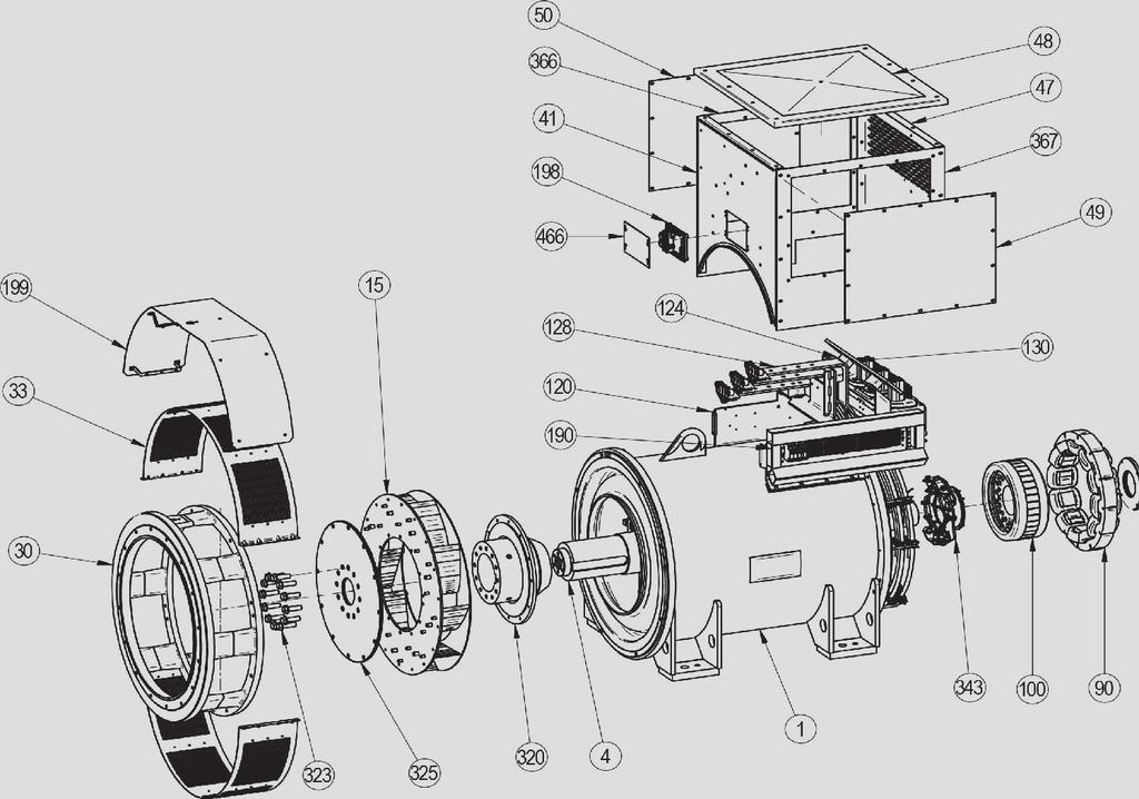
15 4.6 - Dismantling, reassembly During the warranty period, this operation should only be carried out in an approved workshop or in our factory, otherwise the warranty may be invalidated. Whilst being handled, the machine should remain horizontal (rotor not locked in position). Check how much the machine weighs before choosing the lifting method. Access to connections and the regulation system Access directly by removing the box lid (48) or the AVR access door (466). Replacing the NDE bearing - Remove the air intake grille (51). - Remove the lid of the protective cover (48) and the side panels (366) and (367). - Remove the hook (21) and the cover rear panel (365). - Fit a M10 lifting ring (weight to handle: 300kg) on both top sides of the endshied in the tapping provided for this purpose. - Disconnect the exciter wires (5+,6-). - Remove the screws (72) from the inner bearing cap (78). - Remove the screws (37). - Remove the shield (36). - Take out the antifriction bearing (70) using a puller with a central screw (see drawing below). Tools required To fully dismantle the alternator, we recommend using the tools listed below : - 1 ratchet spanner + extension - 1 torque wrench - 1 set of flat spanners : 8 mm, 10 mm, 18 mm - 1 socket set : 8, 10, 13, 16, 18, 21, 24, 30 mm - 1 socket with male ferrule: 5 mm - 1 puller Screw tightening torque See section 5.4. Access to diodes - Open the air intake grille (51). - Disconnect the diodes. - Disconnect the diodes using an ohmmeter or a battery lamp. - Remove the surge suppressor (347). - Remove the 6 H mounting nuts for the diode bridges on the support. - Change the fitted caps, respecting the polarity. - Fit the new antifriction bearing onto the shaft after heating it by induction to approximately 80 C. - Mount the new preloading (wavy) washer (79) in the shield (36). - Screw a threaded rod into the inner bearing cap (78). - Refit the end shield on the machine using a dowel and nut in the shaft extension (see drawing). 15

. - Remove the DE shield (30) if it is a twinbearing machine.")
, remove the threaded rod, fit the other screws and tighten up the assembly. - Tighten the shield screws (37). - Reconnect exciter field wires E+, E-.")
16 - Slide the threaded rod into the shield hole to make it easier to assemble (see diagram). Ball single bearing Ball double bearing Roller single bearing Roller double bearing Slide the threaded rods into the shield holes to make it easier to assemble (see basic diagram). - Tighten the bottom inner bearing cap screws (78), remove the threaded rod and fit the other screws. - Tighten the shield screws (31). - Refit the air outlet grille (33). Dismantling the rotor assembly - Remove the NDE shield (36). - Remove the DE shield (30) if it is a twinbearing machine. - Support the DE rotor (4) with a strap or with a support constructed in accordance with the following drawing. - Move the strap as the rotor moves in order to distribute the weight evenly over it. - Fit a inner bearing cap screw (78), remove the threaded rod, fit the other screws and tighten up the assembly. - Tighten the shield screws (37). - Reconnect exciter field wires E+, E-. - Finish reassembling the cover. WARNING When dismantling the shields, you will need to change the antifriction bearings and the preloading (wavy) washer. Replacing the DE bearing - Remove the air outlet grille (33). - Remove the screws (31) from the DE shield and the 4 screws (62) from the inner bearing retainer. - Remove the shield (30). - Take out the ball bearing (60) using a puller with a central screw. - Fit the new bearing, after heating it by induction to approximately 80 C. - Screw two threaded rods into the inner bearing cap (68). - Refit the shield (30) on the machine. WARNING When dismantling the rotor involves changing parts or rewinding, the rotor must be rebalanced. 16
17 Reassembling the machine - Mount the rotor (4) in the stator (1) (see drawing above) taking care not to knock the windings. - Slide the threaded rod into the shield hole to make it easier to assemble (see diagram). - Fit an inner bearing cap screw (78), remove the threaded rod, fit the other screw and tighten up the assembly. - Tighten the shield screws (37). - Reconnect exciter field wires E+, E-. - Finish reassembling the cover. - Refit the flange (30) on the stator (1). - Tighten the screws (31). If using a twin-bearing machine: - Finish reassembling the cover. - Screw a threaded rod into the inner bearing cap (68). - Refit the shield (30) on the machine. - Slide the threaded rod into the shield hole to make it easier to assemble (see diagram). - Fit the inner bearing cap screws (68), remove the threaded rod, fit the other screw and tighten up the assembly. - Tighten the shield screws (31). - Refit the air outlet grille (33). - Check that the machine assembly is correctly mounted and that all screws are tightened DE filter 417 Dismantling and reassembly of the filters - Remove the grille (417) then take out the filter (418). Change the filter if necessary; please refer to section 4.2 for cleaning the filter. To replace, follow the instructions in reverse order. Terminal box filter of the PMG The PMG reference is : PMG 8. See the PMG manual ref : NDE filter Table of characteristics Table of average values. Alternator - 4 poles - 50 Hz - Standard winding 400V. 17
18 The voltage and current values are given for no-load operation and operation at rated load with separate field excitation. All values are given at ± 10% and may be changed without prior notification (for exact values, consult the test report). Average values Resistances at 20 C (Ω) Type L/N stator Rotor Exciter field Armature S5-S S L L Resistance of AREP auxiliary windings at 20 C (Ω) Type Auxil wdg: X1, X2 Auxil wdg: Z1, Z2 S5-S S L L Field excitation current i exc (A) Symbols: «i exc»: excitation current of the exciter field. Voltage of auxiliary windings at no load Type Auxil wdg: X1, X2 Auxil wdg: Z1, Z2 50 Hz 100V 10V 60 Hz 120V 12V Table of weights (values given for information only) Type Total weight (kg) Rotor (kg) S5-S S L L After operational testing, it is essential to replace all access panels or covers. Type No load At rated load S S S L L For 60 Hz machines, the «i exc» values are approximately 5 to 10% lower. 18
19 5 - SPARE PARTS First maintenance parts Emergency repair kits are available as an option. They contain the following items : Emergency kit AREP ALT 523 KS 001 AVR R Diode bridge assembly - Surge suppressor - Emergency kit AREP ALT 523 KS 002 AVR D 510C - Diode bridge assembly - Surge suppressor - Single-bearing kit ALT 523 KB 002 Non drive end bearing - «O» ring - Preloading (wavy) washer - Double-bearing kit ALT 523 KB 001 Non drive end bearing - Drive end bearing - «O» ring - Preloading (wavy) washer Technical support service Our technical support service will be pleased to provide any additional information you may require. When ordering spare parts, you should indicate the complete machine type, its serial number and the information given on the nameplate. Address your enquiry to your usual contact. Part numbers should be identified from the exploded views and their description from the parts list. Our extensive network of service centres can dispatch the necessary parts without delay. To ensure correct operation and the safety of our machines, we recommend the use of original manufacturer spare parts. In the event of failure to comply with this advice, the manufacturer cannot be held responsible for any damage. After operational testing, it is essential to replace all access panels or covers Accessories Space heater when stopped The space heater must run as soon as the alternator stops. It is installed at the rear of the alternator. Its standard power is 500W with 220V or 250W with 110V on request. Caution : the power supply is present when the alternator has stopped. Connection accessories - 6-wire machines Requirements for coupling (F): - 3 links. 19
20 5.4 - Exploded view, parts list and tightening torque Single-bearing 20
21 Double bearing 21
22 Ref. Qty Description Screw Ø Torque N.m Ref. Qty Description Screw Ø 1 1 Stator assembly Exciter field M Rotor assembly Air inlet cover IP Fan Air inlet cover IP Lifting ring Exciter armature Drive end shield M Terminal support Protective grille M Terminals insulated supports Torque N.m Exciter end shield M Starting range Cover front panel M Neutral link Terminal box rear lid M Terminal block Terminal box top lid M Voltage regulator (AVR) Inspection door M Protective cover IP Air intake grille M Coupling hub DE bearing Coupling disc Inner bearing cap Fixing screw M NDE bearing Diode bridge assembly M Cover Terminal box side lid Inner bearing cap Terminal box side lid with inspection door Preloading wavy washer AVR inspection door
23 Disposal and recycling instructions We are committed to limit the environmental impact of our activity. We continuously survey our production processes, material sourcing and products design to improve recyclability and diminish our footprint. These instructions are for information purposes only. It is the user responsibility to comply with local legislation regarding product disposal and recycling. The oil and grease from the lubrication system should be considered as a hazardous waste and has to be handled according to local legislation. Recyclable materials Our alternators are mainly built out of iron, steel and copper materials, which can be reclaimed for recycling purposes. These materials can be reclaimed through a combination of manual dismantling, mechanical separation and melting processes. Our technical support department can provide detailed directions on products dismounting upon request. Waste & hazardous materials The following components and materials need a special treatment and need to be separated from the alternator before the recycling process: - electronic materials found in the terminal box, including the Automatic Voltage Regulator (198), Current Transformers (176), interference suppression module (199) and other semi-conductors. - diode Bridge (343) and Surge suppressor (347), found on the alternator rotor. - major plastic components, such as the terminal box structure on some products. These components are usually marked with plastic type information. All materials listed above need special treatment to separate waste from reclaimable material and should be handed to specialized disposal companies. 23
24 24
25 Electric Power Generation Declaration of EC compliance and incorporation This Declaration applies to the generators designed to be incorporated into machines complying with the Machinery Directive Nr 2006/42/EC dated 17 May MOTEURS LEROY-SOMER MLS HOLICE STLO.SRO MOTEURS LEROY-SOMER DIVISION LEROY-SOMER Boulevard Marcellin Leroy SLADKOVSKEHO 43 1, rue de la Burelle STREET EMERSON ANGOULEME OLOMOUC Boite Postale 1517 Nr4 Parcul Industrial Tetarom 2 FRANCE CZECH REPUBLIC ST JEAN DE BRAYE CLUJ NAPOCA FRANCE ROMANIA Declares hereby that the electric generators of the types: LSA40 - LSA LSA LSA LSA LSA LSA LSA LSA LSA LSA LSA LSA LSA LSA LSA53 - LSA LSA54 - LSA TAL040 - TAL042 - TAL044, as well as their derivatives, manufactured by Leroy-Somer or on Leroy-Somer's behalf, comply with the following International Standards and Directive: - EN and IEC , and ISO Reciprocating internal combustion engine driven alternating current generating sets. Part 3. Alternating current generators for generating sets - Low Voltage Directive Nr 2014/35/UE dated 26 February 2014 Furthermore, these generators, designed in compliance with the Machine Directive Nr 2006/42, are therefore able to be incorporated into Electrical Gen-Sets complying with the following International Directives: - Machinery Directive Nr 2006/42/EC dated 17 May EMC Directive Nr 2014/30/UE dated 26 February 2014, as intrinsic levels of emissions and immunity are concerned WARNING: The here mentioned generators should not be commissioned until the corresponding Gen-Sets have been declared in compliance with the Directives Nr 2006/42/EC and 2014/30/UE, as well as with the other relevant Directives. Leroy-Somer undertakes to transmit, in response to a reasoned request by the national authorities, relevant information on the generator. Technical Managers J.P. CHARPENTIER - Y. MESSIN 4152 en / k The contractual EC Declaration of Conformity and Incorporation can be obtained from your contact on request. 25
26 26

27 Service & Support Our worldwide service network of over 80 facilities is at your service. This local presence is our guarantee for fast and efficient repair, support and maintenance services. Trust your alternator maintenance and support to electric power generation experts. Our field personnel are 100% qualified and fully trained to operate in all environments and on all machine types. We know alternators operation inside out, providing the best value service to optimize your cost of ownership. Where we can help: Conception Consulting & specification Maintenance contracts Life Extension Remanufacturing System upgrade Start-up Commissioning Training Optimization Monitoring System audit Operation Genuine spare parts Repair services Contact us: Americas: +1 (507) Europe & International: Asia Pacific: China: India: Scan the code or go to:
28
LSA 50.2 Low Voltage Alternators - 6 pole
 This manual concerns the alternator which you have just purchased. We wish to draw your attention to the contents of this maintenance manual. SAFETY MEASURES Before using your machine for the first time,
LSA 50.1 / LSA Low Voltage Alternators - 4 pole. Installation and maintenance
 41 124 198 62 22 284 60 31 367 28 343 347 30 68 15 33 34 4 1 This manual concerns the alternator which you have just purchased. We wish to draw your attention to the contents of this maintenance manual.
LSA Low Voltage Alternators - 4 pole. Installation and maintenance
 198 41 466 322 325 320 15 30 321 1 31 37 343 347 100 78 70 323 33 34 4 28 This manual concerns the alternator which you have just purchased. We wish to draw your attention to the contents of this maintenance
A E. P.M.G. range. Low Voltage Alternators - 4 pole. Installation and maintenance
 A E This manual concerns the P.M.G. alternator which which you you have have just just purchased. We wish to draw your attention to the contents of this maintenance manual. SAFETY MEASURES Before using
VOLT POT 1K R220. OPEN FOR 60 Hz STAB A.V.R. R220. Installation and maintenance
 VOLT POT 1K 110 0V E+ E- OPEN FOR 60 Hz STAB This manual concerns the alternator which you have just purchased. We wish to draw your attention to the contents of this maintenance manual. SAFETY MEASURES
LSA 46.3 Low Voltage Alternators - 4 pole
 This manual concerns the alternator which you have just purchased. We wish to draw your attention to the contents of this maintenance manual. SAFETY MEASURES Before using your machine for the first time,
TAL 046. Low Voltage Alternators - 4 pole. Installation and maintenance. Three-phase 6 and 12-wire
 Three-phase 6 and 12-wire This manual concerns the alternator which you have just purchased. We wish to draw your attention to the contents of this maintenance manual. SAFETY MEASURES Before using your
TAL 044. Low Voltage Alternators - 4 pole. Installation and maintenance. Three-phase 6 and 12-wire Dedicated single-phase 4-wire
 323 322 31 32 16 15 325 320 40 33 30 4 Three-phase 6 and 12-wire Dedicated single-phase 4-wire 1 This manual concerns the alternator which you have just purchased. We wish to draw your attention to the
LSA POLES ALTERNATORS
 3742 en - 2011.03 / g 366 49 131 128 41 124 This manual is to be given to the end user 62 22 284 60 31 198 367 28 343 347 34 33 15 68 30 4 1 3742 en - 2011.03/ g This manual concerns the alternator which
TAL 042. Low Voltage Alternators - 4 pole. Installation and maintenance. Three-phase 6 and 12-wire Dedicated single-phase 4-wire
 Three-phase 6 and 12-wire Dedicated single-phase 4-wire This manual concerns the alternator which you have just purchased. We wish to draw your attention to the contents of this maintenance manual. SAFETY
R250 A.V.R. Installation and maintenance R250 0V E+ E- VOLT STAB FREQ. & L.A.M. CONFIG. 50Hz. 47.5Hz. 57Hz LAM 1 13% 2 25% OFF LAM OFF 9
 110 0V E+ E- VOLT STAB KNEE 47.5Hz OFF 9 SPECIAL 8 KNEE 65Hz 7 OFF KNEE 6 57Hz OFF 7 8 50Hz o 9 0 5 6 1 2 3 4 OFF 1 13% 2 25% 3 OFF 4 13% 5 25% 60Hz FREQ. & L.A.M. CONFIG. This manual concerns the alternator
LSA 42.3 Low Voltage Alternators - 4 pole
 This manual concerns the alternator which you have just purchased. We wish to draw your attention to the contents of this maintenance manual. SAFETY MEASURES Before using your machine for the first time,
GEARLEC - TRACTELEC GT3 / TF3 / TM3
 60 559 551 581 602 550 571 586 546 566 567 572 265 Low Voltage Alternators - 4 pole This manual concerns the alternator which you have just purchased. We wish to draw your attention to the contents of
S.A.E. 5. This manual is to be given to the end user LSA 40-4 POLES ALTERNATORS. Installation and maintenance
 4455 en - 2011.02 / b S.A.E. 5 33 30 343 1 41 124 120 198 100 70 349 This manual is to be given to the end user 15 30 322 4 323 324 33 37 4455 en - 2011.02/ b This manual concerns the alternator which
R231 A.V.R. Installation and maintenance R 231. This manual is to be given to. the end user. Armature 6- Field. Slow-blow fuse 250V 8 A
 Armature 6- Field This manual is to be given to the end user F1 Slow-blow fuse 250V 8 A 110 0V E+ E- 75 mm 140 mm P1 P2 Voltage Stability R 231 This manual concerns the alternator which you have just purchased.
LSA R Air/air heat exchanger - AREP - 4 pole ALTERNATORS - Ex II 3 G. Installation and maintenance. This manual is to be given to.
 474 132 1 This manual is to be given to the end user LSA R 49.1 Air/air heat exchanger - AREP - 4 pole Installation and maintenance This manual concerns the alternator which you have just purchased. The
This manual is to be given to. the end user P.M.G. / ALTERNATORS. Installation and maintenance
 A B C This manual is to be given to the end user Installation and maintenance This manual concerns the PMG which you have just purchased. We wish to draw your attention to the contents of this maintenance
3664 en / c LSA 37-2 POLE - ACC ALTERNATORS. Installation and maintenance
 48 49 184 This manual must be supplied to the end user 15 21 30 188 124 185 4 1 18 70 349 Installation and maintenance This manual concerns the alternator which you have just purchased. The latest addition
LSA POLES ALTERNATOKS
 .. ; ;oy Scooter 4803 en-2011.12/b ALTERNATOKS Installation and maintenancé LEROY-SOMER Installation and maintenance 4803 en -2011.12/b This manual concerns the alternator which you have just purchased.
LSA 37-2 & 4 POLE - ACC ALTERNATORS
 185 0 21 33 60 22 188 This manual must be supplied to the end user 4 Installation and maintenance This manual concerns the alternator which you have just purchased. The latest addition to a whole new generation
LSA & 4 POLE ALTERNATORS
 49 132 124 This manual must be supplied to the end user 323 324 30 4 1 198 120 347 343 100 322 15 33 37 28 EROY-SOMER This manual concerns the alternator which you have just purchased. We wish to draw
4291 en /a R220 A.V.R. Installation and maintenance
 4291 en -10.2008 /a Installation and maintenance LEROY-SOMER Installation and maintenance 4291 en-10.2008/a This manual concerns the alternator which you have just purchased. We wish to draw your attention
Users guide and maintenance manual. Leroy Somer Alternators LSA 43.2 / Pole SHUNT AREP - PMG
 Users guide and maintenance manual eroy Somer Alternators SA 43.2 / 44.2 4 Pole SHUNT AREP - PMG Réf. constructeur : 3434GB-4.33/d-02.04 Réf. GPAO : 33522059401 ind1 This manual concerns the alternator
Réf en /c LSA 37 SHUNT - 2 & 4 POLE ALTERNATORS. Installation and maintenance
 214 214 37 3 124 36 This manual must be supplied to the end user 18 100 70 79 349 91 79 90 91 38 90 51 Installation and maintenance This manual concerns the alternator which you have just purchased. The
LSA 52.3 Low Voltage Alternators - 4 pole
 LSA 52.3 Low Voltage Alternators - 4 pole 1860 to 2500 kva - 50 Hz / 2230 to 3000 kva - 60 Hz Electrical and mechanical data Specially adapted to applications The LSA 52.3 alternator is designed to be
SECTION E I N D E X. Alternator Illustrations General Information Safety Requirements Electrical Checks 6. 4.
 SECTION E I N D E X Alternator Illustrations 3 1. General Information 4 2. Safety Requirements 5 3. Electrical Checks 6 4. Safety 6 5. Do s & Don ts 6 6. Voltage Setting 7 7. Maintenance 8 8. Brushless
PV4 - PIV6. Submersible multistage centrifugal electro-pumps. Installation and maintenance. This manual is to be given to the end user
 Réf. 3483 GB - 4.33/a - 09.2001 This manual is to be given to the end user PV4 - PIV6 Submersible multistage centrifugal Installation and maintenance PV4 - PIV6 1 - GENERAL PV4 and PIV6 series should be
Low Voltage Alternators - 4 pole
 TA-A4 - TA-A47 - TA-A49 18 to 1 kva - 5 Hz / 225 to 5 kva - Hz Electrical and mechanical data Adapted to needs The TA alternator range is designed to meet the specific needs of telecommunications, commercial
Low Voltage Alternators - 4 pole LSA 44.3
 LSA 44.3 70 to 150 kva - 50 Hz / 88 to 188 kva - 60 Hz Electrical and mechanical data Specially adapted to applications The LSA 44.3 alternator is designed to be suitable for typical generator applications,
Installation and maintenance guide LSK. D.C. motors. Reference: 5703 en / a
 Installation and maintenance guide LSK D.C. motors Reference: CONTENTS PAGES PAGES 1 - TOOLS... 3 2 - HANDLING... 3 3 - LOCATION... 3 9 - DISMANTLING... 6 9.1 - Procedure... 6 9.2 - Dismantling the armature
4099 en / a LSA POLES ALTERNATORS. Installation and maintenance
 4 This manual is to be given to the end user Installation and maintenance This manual concerns the alternator which you have just purchased. We wish to draw your attention to the contents of this maintenance
Mounting & Maintenance Instructions OMT1 & OMT2 Motors
 Mounting & Maintenance Instructions OMT1 & OMT2 Motors Seite 1 von 10 Inhalt Seite 1 General information 3 2 Delivery 3 3 Mounting 3 4 Coupling 3 4.1 Direct coupling 3 4.2 Indirect coupling 4 4.2.1 Flat
3946 en / a. This manual is to be given to. the end user. HPM x44. A.C. motor. Installation and maintenance
 This manual is to be given to the end user Installation and maintenance To ensure that the LEROY-SOMER motor you have just purchased is entirely satisfactory, it is essential to adhere to the following
SM Alternators. Manual and Instruction
 A3 Manual and Instruction SM Alternators All copyright is the property of SINOCOX ELECTRO-MECHANICAL FUZHOU CO., LTD. It can not be published without official authorization. Sinocox Electro-Mechanical(Fuzhou)
COMPABLOC. Cb Cb Cb 1504 Installation and maintenance. These instructions should be given to the end user GN
 Réf. 3092-4.33 / a - 2.99 8 7 32 08 67 32 84 68 96 These instructions should be given to the end user 4 80 64 70 30 3 3 39 8 44 66 92 2 4 3 3 309 42 COMPABLOC - Installation and maintenance GN 0090 INSTALLATION
Monocellular centrifugal electro-pumps
 Réf. 2100 - O33 / a - 5.95 This manual must be given to the end user LS Monocellular centrifugal electro-pumps Installation and maintenance 1 - GENERAL The LS range of monobloc electro-pump units should
THREE PHASE AND SINGLE PHASE ASYNCHRONOUS ELECTRIC MOTORS OPERATION AND MAINTENANCE BOOKLET Rev
 MORATTO S.R.L. Electrical Machinery I 31030 PERO DI BREDA (Treviso) Italy Via A Volta, 2 Tel. +390422904032 fax +39042290363 www. moratto.it - moratto@moratto.it THREE PHASE AND SINGLE PHASE ASYNCHRONOUS
MJB. Model. Up to kva. Power. Up to V. Voltages. Frame 160 ± 900. Pole 4, 6, 8, 10 and 12. (over contact MM) Cooling IC 01
 Cooling IC 01") MJB Model Power Voltages MJB Up to 6.500 kva Up to 1.000 V Frame 160 ± 900 Pole 4, 6, 8, 10 and 12 Cooling IC 01 (over contact MM) IP Enclosure Main Applications Sector IP 23. Available up to IP 44 with
MJB Model Power Voltages MJB Up to 6.500 kva Up to 1.000 V Frame 160 ± 900 Pole 4, 6, 8, 10 and 12 Cooling IC 01 (over contact MM) IP Enclosure Main Applications Sector IP 23. Available up to IP 44 with
1. SPECIFICATION. Altitude of motor installation. Information: Resistance and temperature specifications of the PTC thermistor / posistor/.
 1. SPECIFICATION 5 GENERAL INFORMATION Motors with parameters according to the data sheet comply with the requirements of the IEC 60034-1 standard, and IEC 60034-30 class efficiency IE2 Motor versions:
PLSES 4500 IMfinity Platform. IP23 high-speed induction motors Industrial refrigeration Variable speed Frame size 225 to to 480 kw
 IMfinity Platform IP23 high-speed induction motors Industrial refrigeration Variable speed Frame size 225 to 315 100 to 480 kw The answer to the highly demanding cold storage sector Companies that use
MCset kv Medium voltage equipment
 Maintenance Guide PE90014 PE90006 MCset 1-2 - 3 17.5 kv Medium voltage equipment Air-insulated switchboards Metal-enclosed switchgear with moving parts PE90007 PE90008 PE90009 PE90007 Maintenance Guide
F O R M. Installation and Maintenance Manual for FCR Equipped Motors and Gearmotors. 9055E Revised October 2015
 Installation and Maintenance Manual for FCR Equipped Motors and Gearmotors Power Transmission Solutions Regal Beloit America, Inc. 7120 New Buffington Road Florence, KY 41042 Application Engineering: 800
MJH. Model. Up to kva. Power. Up to V. Voltages. Frame 400 ± Pole 4, 6, 8. (over contact MM) Cooling IC 01
 Cooling IC 01") MJH Model Power Voltages MJH Up to 12.500 kva Up to 15.000 V Frame 400 ± 1.250 Pole 4, 6, 8 Cooling IC 01 (over contact MM) IP Enclosure Main Applications Sector IP 23. Available up to IP 44 with filters.
MJH Model Power Voltages MJH Up to 12.500 kva Up to 15.000 V Frame 400 ± 1.250 Pole 4, 6, 8 Cooling IC 01 (over contact MM) IP Enclosure Main Applications Sector IP 23. Available up to IP 44 with filters.
MOUNTING & MAINTENANCE INSTRUCTIONS FOR
 9 Pages / Page 1 MOUNTING & MAINTENANCE INSTRUCTIONS FOR THREEPHASE INDUCTION MOTORS - TYPES DM1 / DMA1 / DMA2 TABLE OF CONTENTS page 1 General information 2 2 Delivery 2 3 Mounting 2 4 Coupling 2 4.1.
AC Induction Motors. Installation and operating instructions
 AC Induction Motors Installation and File No: 48.80 Date: january 28, 2014 Supersedes: 48.80 Date: july 30, 2013 contents Receiving inspection and handling 4 Installation / mounting 4 Location 5 Electrical
INDUSTRIAL GENERATOR SERVICE
 INDUSTRIAL GENERATOR SERVICE PREVENTATIVE MAINTENANCE PROGRAM Customer: Date: Contact Person: Work Order #: Contact Number: ( ) Technician: INSPECTION COMPONENTS 1. GENERAL Check fuel tank level. Check
SERVO MOTORS BRUSHLESS SERVO MOTORS OPERATING INSTRUCTIONS 2016
 SERVO MOTORS BRUSHLESS SERVO MOTORS OPERATING INSTRUCTIONS 2016 3009/16 en Ed.02.2016 Read these Operating Instructions before performing any transportation, installation, commissioning, maintenance or
MJB. Model. Up to kva. Power. Up to V. Voltages. Frame 160 ± 900. Pole 4, 6, 8, 10 and 12. (over contact MM) Cooling IC 01
 Cooling IC 01") MJB Model Power Voltages MJB Up to 6.500 kva Up to 1.000 V Frame 160 ± 900 Pole 4, 6, 8, 10 and 12 Cooling IC 01 (over contact MM) IP Enclosure Main Applications Sector IP 23. Available up to IP 44 with
MJB Model Power Voltages MJB Up to 6.500 kva Up to 1.000 V Frame 160 ± 900 Pole 4, 6, 8, 10 and 12 Cooling IC 01 (over contact MM) IP Enclosure Main Applications Sector IP 23. Available up to IP 44 with
ASYNCHRONOUS MOTORS THREE-PHASE MOTORS SINGLE-PHASE MOTORS BRAKE MOTORS INSTRUCCIONES DE SERVICIO OPERATING INSTRUCTIONS 2016
 ASYNCHRONOUS INSTRUCCIONES DE SERVICIO MOTORS THREE-PHASE MOTORS SINGLE-PHASE MOTORS BRAKE MOTORS OPERATING INSTRUCTIONS 2016 3006/16 en Ed.02.2016 Read these Operating Instructions before you transport,
Installation and maintenance guide D.C. MOTORS. Reference: 5702 en / a
 Installation and maintenance guide D.C. MOTORS Reference: CONTENTS 1 - RECEIPT...3 2 - STORAGE...3 2.1 - Storage area...3 2.2 - Long-term storage... 3 - ENVIRONMENT...3 4 - COMMISSIONING... 3-4 4.1 - Installation...3
Pro Booster 802Li. Please read and fully understand the instructions in this manual before operation. Keep this manual safe for future reference.
 Please dispose of packaging for the product in a responsible manner. It is suitable for recycling. Help to protect the environment, take the packaging to the local amenity tip and place into the appropriate
INDEX Section Page Number Remarks
 INDEX Section Page Number Remarks Synchronous Alternators 2 4 General Fault Finding Capacitors 5 6 Fault Finding & Testing Diodes,Varistors, EMC capacitors & Recifiers 7 10 Fault Finding & Testing Rotors
Appendix: Safety and application notes for... 15
 Contents Safety... 2 Warnings... 2 Symbols used in this manual... 2 Operator s safety... 2 Avoid filter module damage... 2 DC-link resonance... 2 Description... 3 Description... 3 Ordering numbers, 380-415
Pan and Tilt Head CDD2416-T
 Pan and Tilt Head CDD2416-T Installation guide Before attempting to connect or operate this product, please read these instructions completely Williams Electronics Ltd www.w-e.co.uk Tel: +44 (0)2921 660
720W PORTABLE GENERATOR
 720W PORTABLE GENERATOR MODEL NO: G720 PART NO: 8857800 OPERATION & MAINTENANCE INSTRUCTIONS LS0214 INTRODUCTION Thank you for purchasing this CLARKE 720W Portable Generator Before attempting to use this
PANCAKE CAPACITOR GENERATOR Installation, Operation and Maintenance Manual
 PANCAKE CAPACITOR GENERATOR Installation, Operation and Maintenance Manual A Regal Brand TABLE OF CONTENTS INTRODUCTION 2 General Data 2 Initial Inspection 2 SAFETY 2 INSTALLATION 3 Location / Environment
ELECTRIC HOIST MODEL NO: CH2500B, CH4000B OPERATION & MAINTENANCE INSTRUCTIONS PART NO: ,
 ELECTRIC HOIST MODEL NO: CH2500B, CH4000B PART NO: 7630386, 7630391 OPERATION & MAINTENANCE INSTRUCTIONS ORIGINAL INSTRUCTIONS LS0517 - Iss 5 INTRODUCTION Thank you for selecting this Clarke Electric Hoist.
Operating and Installation Instructions Diaphragm Vacuum Pumps and Compressors
 Operating and Installation Instructions Diaphragm Vacuum Pumps and Compressors Type range: UN813.3ANI UN813.4ANI UN813.3ANDCB UN813.4ANDCB UN813.5ANI Fig. 1: UN813.3ANI Fig. 2: UN813.4ANI You have selected
USE AND INSTALLATION HANDBOOK
 Date : 10/02/14 Rev. 01 PR.T : FG006172 USE AND INSTALLATION HANDBOOK DUPLEX-UP CONTROL PANEL FOR 2 ELECTRIC PUMPS WITH CURRENT CONTROL. DUPLEX-UP Via Enrico Fermi 8-35020 Polverara PD Tel.049/9772407
VEM motors Thurm GmbH
 VEM motors Thurm GmbH Installation, Operating and Maintenance Instructions Single-Phase Squirrel-Cage Induction Motors, Standard Version March 2005 1. General To avoid damage to the motors and equipment
D58 Series Brake Instructions
 D58 Series Brake Instructions 4740 W. Electric Avenue Milwaukee, WI 53219 414/672-7830 FAX 414/672-5354 www. dingsbrakes.com Safety information 2 Safety information 2.1 Persons responsible for the safety
ELECTRIC HOIST MODEL NO: CH2500B, CH4000B OPERATION & MAINTENANCE INSTRUCTIONS PART NO: , LS1010
 ELECTRIC HOIST MODEL NO: CH2500B, CH4000B PART NO: 7630386, 7630391 OPERATION & MAINTENANCE INSTRUCTIONS LS1010 INTRODUCTION Thank you for purchasing this CLARKE Electric Hoist. Before attempting to use
1100W PORTABLE GENERATOR
 1100W PORTABLE GENERATOR MODEL NO: G1200 PART NO: 8010110 OPERATION & MAINTENANCE INSTRUCTIONS LS0312 INTRODUCTION Thank you for purchasing this CLARKE 1100W Portable Generator. Before attempting to use
Switching DC Power Supply
 99 Washington Street Melrose, MA 02176 Phone 781-665-1400 Toll Free 1-800-517-8431 Visit us at www.testequipmentdepot.com Model 1693, 1694 Switching DC Power Supply INSTRUCTION MANUAL 1 Safety Summary
 Motor Trouble-Shooting Chart Caution:. Disconnect power to the motor before performing service or maintenance.. Discharge all capacitors before servicing motor.. Always keep hands and clothing away from
LSC500S3. Powered by Cummins 50HZ. Water-cooled. Three Phase. Diesel KVA 500 KW 400. Standby Power
 LSC500S3 Powered by Cummins 50HZ Water-cooled Three Phase Diesel Model LSC500S3 Standby Power KVA 500 KW 400 Prime Power KVA 450 KW 360 Frequency Hz 50 Voltage V 230/400 Rated speed rpm 1500 Cummins has
Electromagnetic single disc clutches E210 and E220
 SM307gb - rev 11/04 S E R V I C E Electromagnetic single disc clutches E210 and E220 M A N U A L WARNER ELECTRIC EUROPE Rue Champfleur, B.P. 20095, F- 49182 St Barthélemy d Anjou Cedex Tél. +33 (0)2 41
Contact us. Catalog Low voltage generators for diesel and gas engines Industrial Marine applications - series Standard series
 Contact us Catalog Low voltage generators for diesel and gas engines Industrial Marine applications - series Standard series We provide motors and generators, services and expertise to save energy and
CPLS Drip-proof 3-phase induction motors
 Installation and maintenance IMPORTANT These symbols appear in this document whenever it is important to take special precautions during installation, operation, maintenance or servicing of the motors.
HCI 534E/544E - Technical Data Sheet
 HCI 34E/44E - Technical Data Sheet SPECIFICATIONS & OPTIONS STANDARDS Newage Stamford industrial generators meet the requirements of BS EN 60034 and the relevant section of other international standards
HCI 434E/444E - Technical Data Sheet
 HCI 434E/444E - Technical Data Sheet SPECIFICATIONS & OPTIONS STANDARDS Newage Stamford industrial generators meet the requirements of BS EN 60034 and the relevant section of other international standards
SIP Direct Drive Oil-Lube Air Compressors - Operating & Maintenance Instructions
 SIP Direct Drive Oil-Lube Air Compressors - Operating & Maintenance Instructions Please read and fully understand the instructions in this manual before operation. Keep this manual safe for future reference.
80 Litre Suction Oil Drainer With Inspection Chamber
 Please dispose of packaging for the product in a responsible manner. It is suitable for recycling. Help to protect the environment, take the packaging to the local amenity tip and place into the appropriate
Rescue Pac. Please read and fully understand the instructions in this manual before operation. Keep this manual safe for future reference
 Please dispose of Packaging for the product in a responsible manner. It is suitable for recycling. Help to protect the environment, take the packaging to the local amenity tip and place into the appropriate
XR500B Universal Voltage Regulator
 XR500B Universal Voltage Regulator The XR500B is a unique voltage regulator that is designed specifically for Professional Electrical Generator Service and Repair Technicians. The XR500B incorporates patented
INSTALLATION OPERATION & MAINTENANCE INSTRUCTIONS For THREE-PHASE INDUCTION MOTORS TYPE HJN / HJA
 INSTALLATION OPERATION & MAINTENANCE INSTRUCTIONS For THREE-PHASE INDUCTION MOTORS TYPE HJN / HJA Fig.1 Types of mounting GENERAL INFORMATION This manual concerns standard three-phase TEFC induction motors,
Installation, operation and maintenance manual
 Installation, operation and maintenance manual HCT1LX30 FULL RISE SCISSOR LIFT READ THIS ENTIRE MANUAL BEFORE INSTALLATION TO ENSURE CORRECT OPERATION AND A LONG SERVICE LIFE 2 Tiraines str. Riga, LV 1058
UCI224F - Winding 25. Technical Data Sheet APPROVED DOCUMENT
 - Winding 25 Technical Data Sheet SPECIFICATIONS & OPTIONS STANDARDS Stamford industrial generators meet the requirements of BS EN 60034 and the relevant section of other international standards such as
BAH series Use and Maintenance Manual
 Page 1 of 15 BAH 225-280 series Use and Maintenance Manual Page 2 of 15 We would like to thank you for trusting us and buying our product. Field of application Before starting the motor, it s necessary
Installation guide. Mb 3101, Mb Drive systems. Part number: 2910 en / p
 Installation guide Mb 30, Mb 000 Drive systems Part number: 90 en - 07.08 / p INSTALLATION - Mb 30, Mb 000 - DRIVE SYSTEMS This document complements the general instructions ref. 557 (recommendations),
LSC220S3. Powered by Cummins 50HZ. Water-cooled. Three Phase. Diesel KVA 220 KW 176. Standby Power
 LSC220S3 Powered by Cummins 50HZ Water-cooled Three Phase Diesel Model LSC220S3 Standby Power KVA 220 KW 176 Prime Power KVA 200 KW 160 Frequency Hz 50 Voltage V 230/400 Rated speed rpm 1500 Cummins has
UCDI224F - Technical Data Sheet
 - Technical Data Sheet SPECIFICATIONS & OPTIONS STANDARDS Newage Stamford industrial generators meet the requirements of BS EN 60034 and the relevant section of other international standards such as BS000,
Certificate of Incorporation (Typical)
") Certificate of Incorporation (Typical) Declaration We Varley Pump Limited hereby declare that the following machinery has been designed to be safely incorporated into other machinery and must not be put
Certificate of Incorporation (Typical) Declaration We Varley Pump Limited hereby declare that the following machinery has been designed to be safely incorporated into other machinery and must not be put
ELECTRIC POWER GENERATION INDUSTRIAL, CUSTOM-ENGINEERED AND SPECIAL ALTERNATORS FOR ALL APPLICATIONS
 ELECTRIC POWER GENERATION INDUSTRIAL, CUSTOM-ENGINEERED AND SPECIAL ALTERNATORS FOR ALL APPLICATIONS GENERATING A POWERFUL FUTURE Leroy-Somer Electric Power Generation is the global leader for alternators
3. Operating instructions: Minor 200
 1. Technical specifications 3. Operating instructions: Minor 200 Copyright 2015 by Endecotts Ltd. 13 1. Setting up Technical specifications SIEVE SHAKER MODEL: Minor 200 General Information The Minor 200
1200W INVERTER GENERATOR
 1200W INVERTER GENERATOR MODEL NO: IG1200 PART NO: 8877070 OPERATION & MAINTENANCE INSTRUCTIONS LS0117 INTRODUCTION Thank you for purchasing this CLARKE 1200W Inverter Generator. Before attempting to use
SM6. instructions for use. SM cubicle. MV distribution factory built assemblies at your service. Anglais
 SM6 Anglais MV distribution factory built assemblies at your service instructions for use SM cubicle foreword... 3 symbols and conventions... 3 as per iso 3864---2... contact the Schneider Electric service
HCI434C/444C - Winding 17 APPROVED DOCUMENT. Technical Data Sheet
 - Winding 17 Technical Data Sheet SPECIFICATIONS & OPTIONS STANDARDS TERMINALS & TERMINAL BOX Stamford industrial generators meet the requirements of BS EN 34 and the relevant section of other international
Wind Turbine Generators Synchronous and Doubly-Fed Induction Generators
 Synchronous and Doubly-Fed Induction Generators Installation and maintenance - Generic PRELIMINARY STATEMENTS This manual provides installation, operation and maintenance instructions for your generator.
LSP88S3. Powered by 50HZ. Water-cooled. Three Phase. Diesel KVA 88 KW 70. Standby Power
 LSP88S3 Powered by 50HZ Water-cooled Three Phase Diesel Model LSP88S3 Standby Power KVA 88 KW 70 Prime Power KVA 80 KW 64 Frequency Hz 50 Voltage V 230/400 Rated speed rpm 1500 Perkins is one of the largest
UCI224C - Technical Data Sheet
 UCI224C - Technical Data Sheet UCI224C SPECIFICATIONS & OPTIONS STANDARDS Newage Stamford industrial generators meet the requirements of BS EN 60034 and the relevant section of other international standards
UCDI274J - Technical Data Sheet
 UCDI274J - Technical Data Sheet UCDI274J SPECIFICATIONS & OPTIONS STANDARDS Newage Stamford industrial generators meet the requirements of BS EN 60034 and the relevant section of other international standards
3 Ton Trolley Jack. Please read and fully understand the instructions in this manual before operation. Keep this manual safe for future reference.
 Please dispose of packaging for the product in a responsible manner. It is suitable for recycling. Help to protect the environment, take the packaging to the local amenity tip and place into the appropriate
SHORT-STOP. Electronic Motor Brake Type G. Instructions and Setup Manual
 Electronic Motor Brake Type G Instructions and Setup Manual Table of Contents Table of Contents Electronic Motor Brake Type G... 1 1. INTRODUCTION... 2 2. DESCRIPTION AND APPLICATIONS... 2 3. SAFETY NOTES...
UCI274H - Technical Data Sheet
 UCI274H - Technical Data Sheet UCI274H SPECIFICATIONS & OPTIONS STANDARDS Newage Stamford industrial generators meet the requirements of BS EN 60034 and the relevant section of other international standards
James Hamilton Electrical Pty Ltd (Inc in Qld) A.C.N trading as. Power Drive Systems. Generator Control Specialists
 A.C.N trading as. Power Drive Systems. Generator Control Specialists") James Hamilton Electrical Pty Ltd (Inc in Qld) A.C.N. 010 848 389 trading as Power Drive Systems Generator Control Specialists 48A Ainsdale Street Telephone: 0500 800 225 P.O. Box 30 West Chermside, Qld
James Hamilton Electrical Pty Ltd (Inc in Qld) A.C.N. 010 848 389 trading as Power Drive Systems Generator Control Specialists 48A Ainsdale Street Telephone: 0500 800 225 P.O. Box 30 West Chermside, Qld
UCDI224E - Technical Data Sheet
 UCDI224E - Technical Data Sheet UCDI224E SPECIFICATIONS & OPTIONS STANDARDS Stamford industrial generators meet the requirements of BS EN 60034 and the relevant section of other international standards
UCI224F - Technical Data Sheet
 UCI224F - Technical Data Sheet UCI224F SPECIFICATIONS & OPTIONS STANDARDS Newage Stamford industrial generators meet the requirements of BS EN 60034 and the relevant section of other international standards
6L Oil-less Air Compressor 53103
 6L Oil-less Air Compressor 53103 Operating Instructions Please read and save these instructions before attempting to assemble, install, operate or maintain the product. Protect yourself and others by observing
Installation and maintenance CPLS. Drip-proof 3-phase induction motors. Part number: 4240 en / c
 Installation and maintenance CPLS Drip-proof 3-phase induction motors Part number: IMPORTANT These symbols appear in this document whenever it is important to take special precautions during installation,