CATALOGUE. GAS INSULATED SWITCHGEAR 123 kv TYP ZRNG
|
|
|
- Katherine Bradford
- 6 years ago
- Views:
Transcription
1 CATALOGUE GAS INSULATED SWITCHGEAR 123 kv Unser Handelspartner in Deutschland TYP ZRNG ISO 9001:2009 ISO 14001:2005
2 GENERAL INFORMATION The tightly encapsulated ZRNG 123 switchboard is designed for use in 110 kv networks with effectively earthed zero point, in both the newly erected and retrofitted switchboard stations. Its small dimensions and the possibility of connection through a cable, or the overhead line or via encapsulated power lines make it an optimum means for use in switchboard stations installed directly in large industrial plants and in the inside of urban agglomerations. The switchboard consists of a building block type of elements that provide for the possibility of setting up up a large range of various wiring diagrammes proposed by the designer, by adhering to all the requirements imposed on the equipment. The SF 6 gas insulation and a careful workmanship guarantee the high operation reliability of the system. It is characterized especially by: - - The elements of the switchgear are solved as kit what enables to build up the fields of the switchgear according to required diagram of connection. - - The use of an electronegative gas SF6 for insulation and extinguishing medium enables a considerable decrease of switchgear dimensions and especially an optimization of insulating system. - - One-pole encapsulated system of devices and bus-bars guarantees a maximum service reliability and eliminates the origin of three-phase short-circuit. - All parts of the power circuit are protected against environmental influence. - - The constructional and technologic solution guarantees that the gas leakage from encapsulation will be smaller than 1%/year. - - The correct function of the equipment is given by the gas density not by the pressure of the gas which changes with the temperature. For this reason all separated gas spaces are equipped with temperature compensated pressure watcher. - - The drop of gas pressure is signalled in two grades. The first grade signals the need to complete the SF6 gas in the indicated space to the prescribed value. If the gas is not completed and the pressure drop continues, the second grade of signalling will operate. - - The switchgear is protected by earth (chassis) protection in sections according to the agreement with the user which enables also to locate the place of the failure. - - The material and the thickness of the encapsulation are selected so that at origin of indoor failure and at following arc short-circuit the destruction as well as the break through of the encapsulation does not occur till the action of the main protection. - - The expansion of SF6 gas pressure in the encapsulation is limited by destructional fuses which form part of each separated gas space. - - The construction of the switchgear guarantees an inspectionless service during ten years. 2
3 ENCAPSULATION The functional parts of single devices, instrument transformers, cable terminals, connecting parts and bus-bars are located in coverings casted from aluminium alloy or welded from aluminium semiproducts.these coverings of cross or cylindrical shape are ended with flanges covered with aluminium or steel covers. The outdoor outlet is an exception at which the casing of the space filled with SF 6 forms a porcelain insulator. The functions of the encapsulation are the following: - separates the device located inside from outside influences (solar radiation, impurities, moisture) - eliminates the gas leakage and ensures permanent insulating conditions - creates the protection against dangerous contact Inside protections of the switchgear - Safety burst membrane Every gastight space is equipped with destructional fuse (metal membrane) which eliminates the increase of pressure in encapsulation above permited limit. The membrane is equipped with exhausts directed towards delimite places where the operator as a rule does not move. - Gas pressure scanner Because the correct function of the insulating system de- pends on gas density not on its pressure which changes with temperature, the so called temperature compensated scanners of gas pressure with two grades of signalling are used. The first grade is set on pressure 0.418±0.005 MPa and it signals the necessity to refill the gas. This refilling can be done only after a rather long time; the switchgear complies also with the testing voltage at this pressure from point of view of insulation. At decrease of pressure in the circuit breaker on a pressure of the second grade of signalling of 0.405±0.005 MPa the function of the circuit breaker is blocked. The signal of the second grade at other parts of the switchgear can be used according to user, s wish. - Earth protection The switchgear is equipped with earth protection for limi- tation of effects of contingent dielectric breakdown. The principle is based on quick indication of the fault current which flows between the encapsulation and the earth. The encapsulation of the switchgear is divided according to selected logic of effect of the protections on mutually separated spaces from point of view of insulation. These spaces are then connected by Cu-bands on which the transformer of earth protection with the earth is put on. The transformer has as a rule these parameters: ratio 400/5A, 10 VA, n < 5. The parameters depend on the earth protection logic. 3
4 SPECIFICATION values of the encapsulated switchgear type ZRNG Typ Rated voltage Rated withstanding voltage at. impulse (1,2/50 µs) ZRNG kv 123 kv 550 Rated withstanding voltage at. impulse (1,2/50 µs) in disconnected path of circuit breaker and disconnector Rated short-time withstanding alternating voltage (50 Hz/1 min) Rated short-time withstanding alternating voltage (50 Hz/1 min) in disconnected path of circuit breaker and disconnector Rated frequency Rated current of outlet Rated current of bus-bars Rated short-time current 1s Short-time current 2s Rated dynamic current Rated work overpressure kv 630 kv 230 kv 265 Hz 50 A 1250 A 1600 ka 25 ka 25 ka 63 MPa 0,35 Rated values of circuit breaker Rated current Rated symmetrical breaking current rated making current A 1600 ka 25 ka 63 rated switching cycle of circuit breaker Rated voltage of auxiliary circuits 0-03 sec-co-3 min-co 60; 220 V DC 230 V AC SWITCHGEAR The switchgear ZRNG is one-pole tightly encapsulated switchgear insulated with SF 6 gas.it consists of switching devices, instrument transformers, bus-bars, inlet elements and connecting parts in unit-built configuration. All its parts are independently encapsulated and mutually conected by means of flanged connections equipped with sealing "O" rings. The set of instruments is fixed on a supporting construction by means of a set of regulation elements which enable their correct assembly. The supporting construction is equipped with 4
5 four wheels which can be heightly adjusted. These wheels enable the movement of the switchgear on rails parallely with the bus-bar system of the switchgear. The mechanical stress originating by dilatation of the bus-bar system at temperature changes is eliminated by this possibility of field movement of the switchgear. The unit-built configuration enables the assembly of switchgear fields with one as well as two systems of bus-bars. It enables also the enlargement of already mounted switchgear on both ends without substantial disassembly of already mounted devices. The switchgear field is divided by conical insulators in several mutually gas-tightly separated spaces. Single spaces are equipped with inlet valve, system of gas leakage indication and protection against dangerous increase of gas pressure. The encapsulation of corresponding spaces of single phases are mutually connected with earthing conductor which is connected on supporting construction of the field through the transformer of earth protection. FIELD OF SWITCHGEAR 1,2 bus-bars 3 bus-bar disconnector 4 circuit breaker 5 instrument current transformer 6 instrument voltage transformer 7 cable terminal 8 outlet short-circuiting device 9 bus-bar short-circuiting device 5
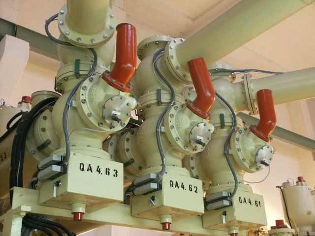
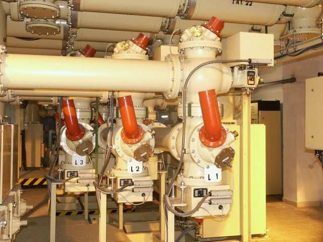
6 CIRCUIT BREAKER The circuit breaker consists of three separate onepole en- capsulated units which are mounted on a common basic frame. The conception is characterized by vertical location of the circuit breaker while the current-conductive path can create a fold "U" or "Z". On fig. 2 there is a section through circuit breaker with currentconductive path "U". CIRCUIT BREAKER 1 epoxide insulator 2 casing of circuit breaker 3 upper contact body 4 rose contact 5 movable cylinder 6 transmiting contact 7 lower contact body 9 push-on contacts 10 burning contact system 11 extinguishing jet 12 storage drive 13 insulating draw bar 14 control lever 15 filling valve 16 safety membrane 17 compensated scanner of SF 6 pressure 18 regeneration filter 6

7 DISCONNECTOR The disconnector is constructionally solved with one-pole motor drive. It has a remote control or is controlled from place. The disconnector can be mounted in arbitrary position and according to use in field of the switchgear we distinguish an outlet and a bus-bar disconnector. ANGULAR DISCONNECTOR 1 casing 2,3 insulator with embedding 4 fixed contact 5 body of disconnector 6 movable pin 7 push-on contacts 8 insulating draw bar with a screw 9 drive box The drive box contains an electromotor with a gearbox, chain drives, coupling and signal contacts. The mechanical indicator of disconnector state is also located on the drive box. After dismantling the drive the control of the disconec- tor is electrically blocked, the access to the manual control of the drive is electrically blocked too. The drive shaft can be mechanically secured by the lock. The filling valve, safety membrane and thermally compensated gas pressure scanner are located on an independent cover while at bus-bar disconnector these devices are located in neighbouring casing. At outlet disconnector the current-conductive path is in shape of "L", at bus-bar disconnector in shape of "T". On fig. 3 we can see the change of the body of outlet disconnector into bus-bar disconnector marked by dashed line. In some cases it is advantageous from point of view of switchgear disposition that the currentconductive path would create the letter "I". This condition is fulfilled by a direct disconnector. The description of this disconnector is analogous with the angular disconnector. DIRECT DISCONNECTOR 1 casing 2 insulator with embedding 3 insulator with embedding 4 fixed contact 5 body of disconnector 6 movable pin 7 push-on contacts 8 insulating draw bar 9 drive box 10 cover 7
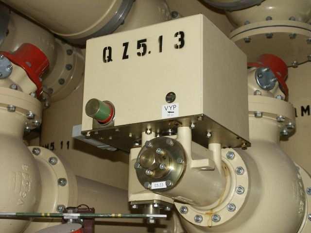
8 SHORT-CIRCUITING DEVICE DISCONNECTOR The short-circuiting device is solved for assembly on casing 1 and it can be performed as an separate device as it is perceptible from fig. 5 or it is mounted on the disconnector. It is created by a separate switching unit 3. The shaft, lever mechanism with switching pin 4, driving spring, pneumatic damper and contact system is located in the body of the short-circuiting device. The fixed contact 5 is fixed on the insulator 6 in the casing 1. The motor storage drive with electromagnetic release with possibility of remote control, the manual drive with electromagnetic release and the driving unit for manual switching with which the device is working as a work earthing device can be mounted according to require- ment on the body of the short-circuiting device. The execution of the short-circuiting device with motor storage drive and electromagnetic release are equipped with emergency manual control. At all executions it is possible to lock the device in earthed position. The short-circuiting device serves to earth the parts of the electrical equipment and so safeguards the security of the operator during the revision works. SHORT-CIRCUITING DEVICE 1 casing of short-circuiting device 2 storage drive 3 switching unit 4 movable pin 5 fixed contact 6 insulator 7 cover with devices INSTRUMENT VOLTAGE TRANSFORMER Max. system voltage Insulating voltage Testing AC voltage Testing impulse voltage 1,2/50 Rated frequency Rated ratio Rated load Class of accuracy Work overpressure of SF 6 gas kv 110 kv 123 kv/1 min. 230 kv 550 Hz 50 kv 110 3//0,1/ 3//0,1/3 VA 75/50 0,3/3P MPa 0,35 8
9 The instrument voltage transformer with inside insulation of gas SF 6 contains three basic parts: cover with accessories 1; casing of transformer 2; insulator with contact system 3. The single instruments voltage transformer 4, fixed by screws to the risers on the inside part of the cover forms the accessories of this cover. The instrument voltage transformer is one-pole insulated, it is the core type. The cylindrical secondary, auxiliary and primary windings are co-axially pushedon the core of the magnetic circuit with section of step polygon. The secondary and auxiliary windings (6) from insulated copper conductor are wound commonly on one insulating casing, the primary winding (7) from insulated copper conductor is wound on an independent insulating casing. Each beginning and end of the secondary and auxiliary winding is connected on an independent terminal connector in the secondary termional board (8) which is fixed on one of the outside risers of the cover and is protected with sealable covering. The beginning of the primary winding is connected to an independent terminal connector of the secondary terminal board. The inside earthing terminal connector is also located in the secondary terminal board. The earthing of the trans- formers can be also done by means of an outside earthing terminal connector (9). The markation of the terminal connectors in the secondary terminal board is the following: secondary winding auxiliary winding beginning of the primary winding Inside earthing terminal connector a, n da, dn N According to customer wishes the instrument voltage transformers can be delivered with two secondary windings and one auxiliary winding. Their loads, voltages and classes of accuracy is necessary to negotiate with manufacturer. Note: The markation of the terminal connectors is according to IEC 186. During the service the terminal connectors marked with letters n, N must be connected by a flat connector marked with earthing mark. At disconnection of the flat connector the insulation of the primary winding can be tested against parts on the potential of the earth. The end of the primary winding is connected to the primary terminal connector which is located on the outside perimeter of the primary winding are equipped with auxiliary electrodes 10; with aim to control the electrical field. Also safety burst membrane with deflector 11, thermally compensated pressure scanner 12 and filling valve 13 per- tain to the accessories located on outside risers of the co- ver. The transformers satisfy the standard ČSN "Instrument transformers" and IEC 186 "Instrument voltage transformers". 9
10 INSTRUMENT VOLTAGE TRANSFORMER 1 cover with accessories 2 transformer casing 3 insulator with contact systém 4 instrument transformer 5 magnetic circuit 6 secondary and auxiliary winding 7 primary winding 8 secondary terminal board 9 earthing terminal connector 10 electrodes 11 membrane with deflector 12 gas pressure scanner 13 filling valve INSTRUMENT CURRENT TRANSFORMER FOR ENCAPSULATION Max. system voltage Insulating voltage Testing AC voltage Testing impulse voltage 1,2/50 Rated frequency Rated primary current Rated secondary current Rated load Class of accuracy Overcurrent number Work overpressure of SF 6 gas kv 110 kv 123 kv/1 min. 230 kv 550 Hz 50 A A A 5 or 1 VA 15 30; ,2 0,5/5P10 < 5 MPa 0,35 The encapsulated instrument current transformer is one-purpose device which can be operated without further arrangement only in the system of the encapsulated switchgear with insulating voltage of 123 kv insulated with SF 6 gas. It serves for feeding protecting and measuring devices. It has two basic parts: encapsulation 1; casting of instrument transformer 2; The transformer encapsulation consists of 4 parts - two flanges (3, 4), casing (5) and reduction (6). The embedding of instrument transformer is screwed on one flange and this whole is fixed to the casing by means of the second flange. This flange has orifices which enable to connect the 10
11 transformer in the encapsulated switchgear. The reduction has the same function. The casing of cylindrical shape has a riser on its outside part in which the outside secondary terminal board (7) is located. The gland bushing determined for inlets from the secondary terminal board to the devices is located on the riser. The secondary terminal board is protected with a cover. The casting of the instrument current transformer is of pushon execution with two magnetic circuits (8). Each of both magnetic circuits is individually closed into the casing for eliminating the danger of effect of mechanical forces on magnetic circuits by which the magnetic characteristics of used magnetic materials deteriorate substantially. The distance wedges from epoxy resin are risered on encapsulated magnetic circuits equipped with secondary winding; these wedges serve to fix the magnetic circuits with winding in casting mould and these circuits are filled with epoxy resin. After rivering the both magnetic circuits with winding create a compact undismantled whole in shape of a hollow cylinder. The inside secondary terminal board is located on one front side, the nuts for fixing the transformer to the flange are embedded on the second front side. The cylindrical electrode (9) is located in the space between the casting of the transformer and the reduction for controlling the electrical field. The terminal connectors both on inside and on outside terminal board are marked with letters 1S1, 1S2, 2S1, 2S2. The marking of the terminal connectors mentioned is according to IEC 185. The transformers comply with the standard ČSN "Instrument transformers" and IEC 185 "Instrument current transformers" by their execution. INSTRUMENT CURRENT TRANSFORMER FOR ENCAPSULATION 1 encapsulation 2 casting of instrument current transformer 3,4 flange 5 casing 6 reduction 7 secondary terminal board 8 magnetic circuit 9 electrode 11
12 CONNECTION OF THE SWITCHGEAR One-core e.h.v. cable with cable ending in required parameters or outside outlet with bushing SF 6 /air are considered for connection of the encapsulated switchgear ZRNG. One-pole encapsulated cable terminal is composed of one-core e.h.v. cable 1 with ending; casing of cable terminal 2 and insulator 3 in which the plugin contact is located. The insulator is equipped with transversal orifices that enables to connect a space of cable terminal with a neighbouring gas space. CABLE TERMINAL 1 cable 2 encapsulation 3 insulator OUTSIDE OUTLET 1 outside insulator 2 encapsulation 3 insulator 4 connecting pin It is necessary to mention also the firm from which is supposed the delivery of e.h.v. cables including their endings (if they are used) at specification of the switchgear for order so that it would be possible to design and to test in time the pertinent encapsulation for the cable terminal. The encapsulated line 3, ended with bushing SF 6 /oil 4 placed in encapsulation 1 can be a further connection of the encapsulated switchgear directly to some type of power transformers. The axial compensators (stainless steel belows) 2 are inserted in the encapsulated line for limiting thermal dilatations and dimensional adaption. 12
13 CONNECTION OF POWER TRANSFORMER 1 casing of bushing 2 axial compensator (stainless steel bellow) 3 encapsulated line 4 bushing SF 6 /oil BUS - BARS The system of bus-bars illustrated is located in upper or lower part of the encapsulated switchgear field in dependence of connection mode, i.e. by cable, outside outlet or encapsulated line. The conductors of the bus-bars 5 are one-pole encapsulated into cylindrical casings 3, 4. The busbar disconnector 1 the transversal conical insulator 7 of which divides the bus-bars on gastight sections in separate switchgear fields is built-in in each field into the bus-bar system. The current-conductive path of the bus-bars is created by copper tube conductors 5 introduced by both ends in slide-in contacts. These contacts are located partly in the insulator of the bus-bar connector 7, partly in the body of the disconnector 8. Each bus-bar part is equipped with protection against inside failures 2, 6 and with filling valve which are common also for bus-bar disonnector. After withdrawal of end covers the bus-bar system is prepared without further arrangements for connection of a further field during eventual expansion of already installed encapsulated switchgear. BUS - BARS 1 odpojovač 2 pouzdro s vývody 3 hlídač hustoty plynu 4 pouzdro přípojnice 5 vodič přípojnice 6 průtržná membrána 7 příčný izolátor 8 těleso odpojovače 1 disconnector 2 casing with outlets 3 scanner of gas density 4 bus-bar casing 5 bus-bar conductor 6 burst membráně 7 transversal insulator 8 disconnector body 13
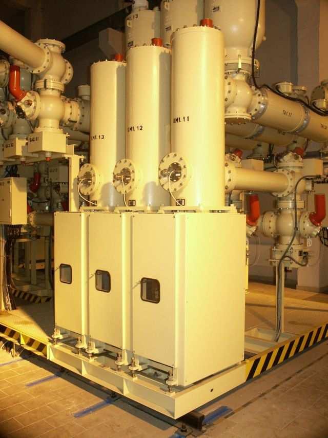
14 The connecting parts are necessary for assembly of the encapsulated switchgear field according to required scheme. These connecting parts ensure mechanical as well as electrical connection among devices. There are cylindrical casings of different length which are usually connected with a cross casing. A copper conductor of necessary length is led in the- ir longitudinal axis. The position of these conductors is ensured by a conical insulator of separate devices, e.g. circuit breakers and disconnectors, the electrical connection with the devices is carried out by push-in contacts. The protections against inside failures and filling valves are usually common with the device on which they are fastened. CONTROL BOX Control boxes form part of the electrical equipment of the encapsulated switchgear. They serve to control the power parts of the encapsulated switchgear and to safeguard the communication among control systems by a supervision. Main functions of control boxes - distribution and protection of small voltages for needs of control and signalling - evaluation of information about pressure and insulating states - signalling of failures - measuring of current states and feeding voltages - electrical blocking of unpermited switching operations - basic control of field - switching evaluated by logic of frame protection The connection of the control box with devices in pertinent field is carried out according to schemes processed for concrete order.there is a scheme of a division of gastight parts of the switchgear illustrated on figure. Each field of the switchgear is equipped with the control box. The cables of auxiliary circuits of circuit breakers, disconnectors and short-circuiting devices ended with multipole plugs are connected into the box into the sockets which are located in both sides of the box. The cables of pressure scanners and transformers of frame protection are connected by three-pole connectors on a frame insert. The connecting terminal boards for instrument transformers and auxiliary cables into neighbouring fields are located also on the frame insert in the lower part of the box. Ready cables ended by multipole connectors form part of the delivery and their assembly on site is quite easy and rapid. The control boxes are mounted outside of the switchgear chasis in the hall of the substation face to separate fields. For orientation the control box is equipped by a blind sche- me with position indicators. 14
15 TESTS IN IVEP The parameters and executions of the encapsulated switchgear ZRNG satisfy the requirements of pertinent standards ČSN and IEC. The technical parameters were verified in the test rooms of IVEP Brno and by synthetic tests in the short-circuit testing station of joint-stock company Testing-Běchovice. The encapsulated switchgear satisfies the standard ČSN IEC 517 ( ) - "Metalically encapsulated gas insulated switchgears for rated voltages of 72.5 kv and higher" as well as the standard ČSN (eqv. to IEC ) - Switching devices and switchgears above 1000 V - Common regulations. The devices were verified according to pertinent subjekt standard ČSN (eqv. IEC ) - "H.v. and e. h. v. a. c. circuit breakers, ČSN (eqv. to IEC ) - "A. c. disconnectors and earthing switches" and ČSN (eqv. to IEC 185, ) "Instrument current and voltage transformers". The encapsulated switchgear except standard testing sequences satisfy at breaking a near shortcircuit and at breaking unloaded outdoor and cable lines. ASSEMBLY AND TESTS OF SWITCHGEAR ON SITE The switchgear is sent to the place of destination in so called transport units dependent on concrete configuration of the switchgear. The transported units are filled by a gas SF6 on overpressure of 20 kpa. If they do not contain insulating elements they are equipped with auxiliary covers and they are transported without gas. The switchgear can be transported by usual means according to agreement between the producer and the customer. The switchgear must be stored in a building in an environment corresponding to climatic resistance N3 according to ČSN The assembly of the switchgear including the connection of control and signalling cables into the control box is carried out by the producer, if need be after agreement with the customer the producer will assist at the total assembly done by the customer. The assembly is carried out only in quite constructionally finished buildings so that the max.dustiness of 1 mg of dust on 1 cubic meter of air would be ensured. The hall must be equipped with a crane with min. loading capacity of 1,500 kg. The assembly consists in composition of the power part of the switchgear (connection of transport units), connection of signal, control and protection and interconnection of control boxes. The connection of lines for measuring and remote control and signal circuits will be ensured by the customer. Also the ending and testing of 110 kv power cables is not carried out by the producer of the switchgear. These works must be ordered at the producer of cables. The gas N2 is blown off from separate gastight sections of the switchgear after the assembly and these parts are filled with pure gas SF6 with pressure 0.45 MPa at 20 C on a 15
16 prescribed pressure according to special regulations. The manipulation with SF6 is realized by so called operating station which enables vacuum degassing, drying and filling of separate spaces. This station is not necessary for the switchgear performance, contingent gas leakage can be completed directly from a pressure bottle equipped with a reduction valve. This bottle forms part of switchgear delivery. After assembly before putting into service the gas insulated metalically encapsulated switchgears must be tested for ensuring the reliability and safety in service, the correct function and dieletrical strength of the device must be checked. These tests are carried out with regard to the possibility of damage during transport, quality of assembly and correctness of connection. The tests are carried out according to ČSN IEC 517( ) - "Metalically encapsulated gas insulated switchgears for rated voltages of 72.5 kv and higher". These tests and checks contain: - voltage tests of electrical strength of insulation of main circuits - insulating tests of control and auxiliary circuits - measuring of main circuits resistence - test of gas leakage - inspections and checks - measurement of gas state MAINTENANCE AND REVISION The switchgear does not claim a maintenance, the drives of breaking dewices, where it is necessary to complete a lubricant in prescribed intervals, form an exception. The time to the 1st revision is 10 years. This time is minimum and after these 10 years on the basis of appreciation of the technical state it can be prolonged up to double. The revision is done by the producer who will consider the possibility to prolong the service. The time will be prolonged if the following number of functions will not be reached at the switching devices. - Circuit breaker 2,000xOC or breaking 30x rated breaking current (in total 900 ka) - Disconnector 2,000xOC - Short-circuiting device 2,000x0C and 10x making into shortcircuit 16
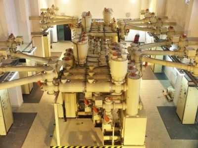
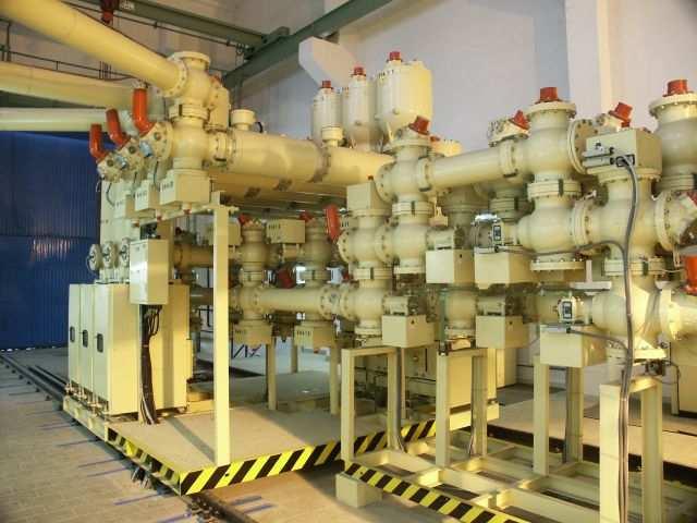
17 EXAMPLES OF LAYOUT SOLUTION On pictures we can see the layout solution of unusual connections. The high variability however enables almost arbitrary layout of different connections, e.g. a so called connection with separate phases, connection with more circuit breakers on a tapping, execution with 3 systems of busbars, if need be auxiliary bus-bar, etc. according to custromer,s wish. FIELD WITH CABLE INLET FIELD OF SWITCH OF BUS BARS 17
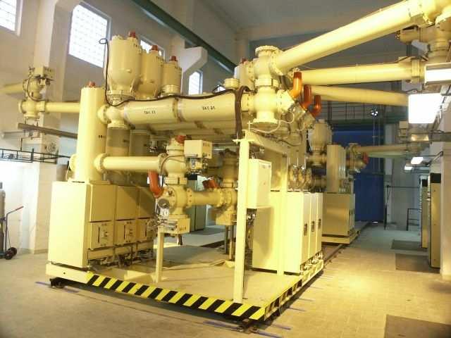
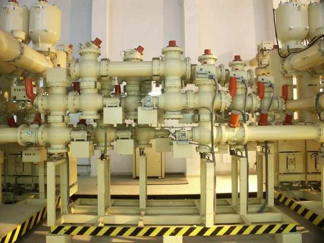
18 FIELD WITH ENCAPSULATED OUTLET TO TRANSFORMER FIELD WITH OUTSIDE OUTLET 18
19 19

20 Domänenstr Dortmund Telefon: Mobil: Web: +49 (0) (0) Manufactured and supplied by: IVEP, a.s. Vídeňská 117a, Brno, Czech Republic Tel.: Fax:
CATALOGUE TRACTION OUTDOOR DISCONNECTORS TYP QAD 3. 3 kv DC; 2500; 3000; 4000; 4500 A
 CATALOGUE TRACTION OUTDOOR DISCONNECTORS Unsere Handelsvertretung in Deutschland TYP QAD 3 3 kv DC; 2500; 3000; 4000; 4500 A ISO 9001:2009 ISO 14001:2005 APPLICATION The outdoor traction disconnectors
CATALOGUE TYP QDS. 7,2-25 kv
 CATALOGUE TYP QDS 7,2-25 kv Unsere Handelsvertretung in Deutschland ISO 9001:2009 ISO 14001:2005 GENERAL INFORMATION switches) are switching devices used to switch electrical circuits in load operating
B kv Gas-insulated Substations
 72.5 145 kv Gas-insulated Substations The increasing demand for electrical power in cities and industrial centres requires the installation of a compact and efficient distribution and transmission network.
SF6 GAS INSULATED METAL ENCLOSED SWITCHGEAR (GIS)
") SF6 GAS INSULATED METAL ENCLOSED SWITCHGEAR (GIS) About company The «Elektroapparat» plant starts its operation in 1922 as a plant manufacturing high-voltage electrical equipment. During the first two
SF6 GAS INSULATED METAL ENCLOSED SWITCHGEAR (GIS) About company The «Elektroapparat» plant starts its operation in 1922 as a plant manufacturing high-voltage electrical equipment. During the first two
B kv T&D GAS INSULATED SWITCHGEAR
 GAS INSULATED SWITCHGEAR B 105 170 300 kv The increasing demand for electrical power in cities and industrial centers necessitates the installation of a compact and efficient distribution and transmission
SF 6 Gas Insulated Switchgear Type SDH314 / SDHa314 for 72.5 to 145 kv
 Three Phase Encapsulated Type SF 6 Gas Insulated Switchgear Type SDH314 / SDHa314 for 72.5 to 145 kv 06B1-E-0002 Small Space Requirement, High Reliability and Safety ー 72.5 to 145 kv GIS, SDH314/SDHa314
Gas Insulated Metal-clad Switchgear, HMGS!
 Medium Voltage HMGS-G10 HYUNDAI Medium Voltage Gas Insulated Metal-clad Switchgear, HMGS! SF6 Gas Insulated Metal-clad Switchgear is an integrated assembly of vacuum circuit breaker, 3-position switch,
SF 6 Gas Insulated Switchgear Type SDH714 for 72.5 to 145 kv
 Three-phase Encapsulated Type SF 6 Gas Insulated Switchgear Type SDH714 for 72.5 to 145 kv 06B1-E-0020 Small Space Requirement, High Reliability and Safety ー 72.5 to 145kV GIS, SDH714 The number of application
OIP Transformer Outdoor Bushings Type COT(C) 125 COT (C) kV to 550kV up to 5000A IEC
 125 COT (C) kV to 550kV up to 5000A IEC") OIP Transformer Outdoor Bushings Type COT(C) 125 COT (C) 1800 24kV to 550kV up to 5000A IEC 60137-2008 Features If you need any transformer bushing proven in operation conditions around the world, Trench
OIP Transformer Outdoor Bushings Type COT(C) 125 COT (C) 1800 24kV to 550kV up to 5000A IEC 60137-2008 Features If you need any transformer bushing proven in operation conditions around the world, Trench
SYSclad switchboard equipped with draw out type vacuum circuit breaker closed dooroperationoperation. SYSclad 12 17,5kV A.
 SYSclad switchboard equipped with draw out type vacuum circuit breaker closed dooroperationoperation 630 3150A SYSclad 12 17,5kV 16 31,5kA Generalities SYSclad is a medium voltage switchboard metal clad
Outdoor live tank vacuum circuit breaker Type OVB-VBF for 24/36/40.5 kv applications
 Outdoor live tank vacuum circuit breaker Type OVB-VBF for 24/36/40.5 kv applications ABB a global leader ABB is a global leader in power and automation technologies that enable utility and industry customers
General. Main electric circuits Fuses compartment Operating mechanisms Cables connection compartment
 General The switchgear must be suitable for 36 kv rated voltage and specifically conceived for the secondary distribution substations in M.V. with either ring or radial type networks. The switchgear must
11kV Compact Switchgear. tec - range. Minimum to Zero SF6 Insulation Gas. Outec Controls
 11kV Compact Switchgear tec - range Minimum to Zero SF6 Insulation Gas. Outec Controls 1 tec xx - 11kV Switchgear Contents 1 tec CB - SF6 Free Switchgear... 3 1.1 Description:... 3 1.2 1.3 Features the
Outdoor live tank SF 6. circuit breaker Type OHB for 24/36/40.5 kv applications
 Outdoor live tank SF 6 circuit breaker Type OHB for 24/36/40.5 kv applications ABB a global leader ABB is a global leader in Power and Automation technologies that enable utility and industry customers
Current accuracy class. Sensor principles
 Indoor Combi Sensor 12, 17.5 and 25 kv 1250 A and 3200 A KEVCD Highest voltage for equipment kv 12.24 Rated continuous primary current A 1250.3200 Rated transformation ratio for current measurement, K
High voltage products PASS M0S 252 kv Innovative solution for transmission substation up to 252 kv
 High voltage products PASS M0S 252 kv Innovative solution for transmission substation up to 252 kv PASS M0S 252 kv Innovation In today s market, the HV substation is increasingly becoming a key element
Resin Impregnated Paper Bushing, Oil to SF 6. , Type GSBK
 1ZSC563-AAA en, Rev. 2 Resin Impregnated Paper Bushing, Oil to SF 6, Type GSBK Technical guide This Technical Guide has been produced to allow transformer manufacturers, and their designers and engineers,
PASS M0. Innovative solutions for distribution substations up to 170 kv
 PASS M0 Innovative solutions for distribution substations up to 170 kv The concept In the today s changing market, the substation is becoming more and more a key element to meet end users requirements
MEDIUM VOLTAGE PRODUCT. TJC 4 Indoor voltage transformers
 MEDIUM VOLTAGE PRODUCT TJC 4 Indoor voltage transformers 2 TJC 4 INDOOR VOLTAGE TRANSFORMERS Parameters Highest voltage for equipment Power frequency test voltage, 1 min. Lightning impulse test voltage
Retrofit for gas-insulated high voltage switchgear (GIS) - 8D1 and 8D2
 - 8D1 and 8D2") Retrofit for gas-insulated high voltage switchgear (GIS) - 8D1 and 8D2 Table of Contents 1 Introduction... 4 2 Description of retrofit circuit-breaker 8DN8... 5 3 Technical data for retrofit circuit-breaker
Retrofit for gas-insulated high voltage switchgear (GIS) - 8D1 and 8D2 Table of Contents 1 Introduction... 4 2 Description of retrofit circuit-breaker 8DN8... 5 3 Technical data for retrofit circuit-breaker
Instruction manual. EK6 Earthing switch 36/40.5 kv
 Instruction manual EK6 Earthing switch 36/40.5 kv Your safety first always! That s why our instruction manual begins with these recommendations: Only install switchgear and/or switchboards in enclosed
CATALOGUE. ELECTRIC DRIVE for indoor MV switching devices TYP SPT CB 40
 CATALOGUE ELECTRIC DRIVE for indoor MV switching devices Unser Handelspartner in Deutschland TYP SPT CB 40 ISO 9001:2009 ISO 14001:2005 GENERAL INFORMATION The SPT... electrically powered motor drive is
CATALOGUE. MANUAL DRIVE for indoor MV switching devices TYP RPP XA 40
 CATALOGUE MANUAL DRIVE for indoor MV switching devices Unsere Handelsvertretung in Deutschland TYP RPP XA 40 ISO 9001:2009 ISO 14001:2005 GENERAL INFORMATION The RPP... drive mechanism is a device used
Product presentation CPT tech Jason Evershed, ABB Transformer Components, May 21st Dry-type transformers Innovative Technology
 Product presentation CPT tech Jason Evershed, ABB Transformer Components, May 21st 2014 Dry-type transformers Innovative Technology What is a dry transformer? ABB manufactures a transformer which does
Metal Clad Air Insulated Switchgear
 Metal Clad Air Insulated Switchgear 1/ SecoGear Metal Clad Switchgear Features Fully metal-clad Equipped with Embedded pole VCB Full Front access (can be installed against wall) Perfect interlocking system
EMPAC Metal enclosed capacitor bank for wind applications
 EMPAC Metal enclosed capacitor bank for wind applications Introduction The EMPAC is a Metal Enclosed Capacitor Bank suitable for voltages between 1 kv and 36 kv for reactive compensation in MV networks
AIR INSULATED EXTENDABLE SWITCHGEAR UP TO 12KV GUIDE
 AIR INSULATED EXTENDABLE SWITCHGEAR UP TO 12KV GUIDE Certificate Number FM35831 APPLICATION Typical Uses and Classification The MSGair switchgear is used in transformer and switching substations mainly
DISTRIBUTION SOLUTIONS. GSec Gas-insulated switching and isolating apparatus
 DISTRIBUTION SOLUTIONS GSec Gas-insulated switching and isolating apparatus GSec is a three-position SF6 gas-insulated switchdisconnector designed for use in medium voltage switchgear for secondary distribution
NXPLUS C Single busbar. Maintenance-free for lifetime
 NXPLUS C Single busbar Maintenance-free for lifetime Energy Distribution Welcome! Page 2 Content Overview Technical data Typicals Panel design Circuit-Breaker panel Busbar Operation Metering Low-voltage
Type SIMOPRIME A4, up to 24 kv, Air-Insulated Medium-Voltage Switchgear
 Circuit-Breaker www.siemens.com/energy Switchgear Type SIMOPRIME A4, up to 24 kv, Air-Insulated Medium-Voltage Switchgear s Technology Circuit-Breaker Switchgear Type SIMOPRIME, up to 17.5 kv, Air-Insulated
OIP Transformer Outdoor Bushings Type COT(C) 125 COT (C) kV to 550kV up to 5000A IEC
 125 COT (C) kV to 550kV up to 5000A IEC") OIP Transformer Outdoor Bushings Type COT(C) 125 COT (C) 1800 24kV to 550kV up to 5000A IEC 60137-2008 Features If you need any transformer bushing proven in operation conditions around the world, Trench
OIP Transformer Outdoor Bushings Type COT(C) 125 COT (C) 1800 24kV to 550kV up to 5000A IEC 60137-2008 Features If you need any transformer bushing proven in operation conditions around the world, Trench
UniPack compact secondary substations (CSS) upto 36 kv For safe, reliable and space saving power distribution solutions
 upto 36 kv For safe, reliable and space saving power distribution solutions") UniPack compact secondary substations (CSS) upto 36 kv For safe, reliable and space saving power distribution solutions ABB a global leader ABB is a global leader in power and automation technologies that
UniPack compact secondary substations (CSS) upto 36 kv For safe, reliable and space saving power distribution solutions ABB a global leader ABB is a global leader in power and automation technologies that
Distribution transformers Efficiency over life-cycle
 Distribution transformers Efficiency over life-cycle ABB a global leader ABB is a global leader in Power and Automation technologies that enable utility and industry customers to improve performance while
Compact Gas Insulated Switchgear (GIS) up to 145kV 126kV,145kV Compact Gas Insulated Switchgear (GIS)
 up to 145kV 126kV,145kV Compact Gas Insulated Switchgear (GIS)") Compact Gas Insulated Switchgear (GIS) up to 45 6,45 Compact Gas Insulated Switchgear (GIS). Standard: IEC 6703. Typical Feature. Great Breaking Character of Circuit Breaker The circuit breaker adopt the
Compact Gas Insulated Switchgear (GIS) up to 45 6,45 Compact Gas Insulated Switchgear (GIS). Standard: IEC 6703. Typical Feature. Great Breaking Character of Circuit Breaker The circuit breaker adopt the
Voltage Rated operating voltage [kv] Rated power frequency withstand voltage [kv] Rated lightning impulse withstand voltage [kv]
![Voltage Rated operating voltage [kv] Rated power frequency withstand voltage [kv] Rated lightning impulse withstand voltage [kv]](/thumbs/80/82203973.jpg "Voltage Rated operating voltage [kv] Rated power frequency withstand voltage [kv] Rated lightning impulse withstand voltage [kv]") BasisBlock MC 1 Standards and Regulations IEC 62271-200 ; VDE 0671-200 ; BS EN 62271-200 Technical Data MC1-12 MC1-24 Voltage Rated operating voltage [kv] 12 24 Rated power frequency withstand voltage
BasisBlock MC 1 Standards and Regulations IEC 62271-200 ; VDE 0671-200 ; BS EN 62271-200 Technical Data MC1-12 MC1-24 Voltage Rated operating voltage [kv] 12 24 Rated power frequency withstand voltage
1ZSC AAA en, Rev. 6. Resin impregnated paper bushing, oil to SF 6., type GSBK Technical guide
 1ZSC563-AAA en, Rev. 6 Resin impregnated paper bushing, oil to SF 6, type GSBK Technical guide Original instruction The information provided in this document is intended to be general and does not cover
Typical Specification
 Engineered to Order Built to Last Typical Specification VAULT VRPFI, TWO POSITION, ROTARY PUFFER SWITCHGEAR PART 1- GENERAL 1.1 DESCRIPTION A. The switch shall consist of manually operated load interrupting,
Air-insulated switchgear UniGear type ZS1
 Air-insulated switchgear UniGear type ZS1 ABB Power Technologies / 1-7074 D 12-03-2003 - Air-insulated switchgear UniGear type ZS1 ABB Power Technologies / 2-7075 D 1 2-03-2003 - Rated voltage kv 12 17.5
TECHNICAL SPECIFICATION OF 11KV SF6 / VCB METAL ENCLOSED, INDOOR (PANEL TYPE) / OUTDOOR RING MAIN UNIT (RMU). (IEC standard equipment)
 / OUTDOOR RING MAIN UNIT (RMU). (IEC standard equipment)") TECHNICAL SPECIFICATION OF 11KV SF6 / VCB METAL ENCLOSED, INDOOR (PANEL TYPE) / OUTDOOR RING MAIN UNIT (RMU). (IEC standard equipment) 1 SCOPE OF SUPPLY This specification covers design, manufacture, shop
TECHNICAL SPECIFICATION OF 11KV SF6 / VCB METAL ENCLOSED, INDOOR (PANEL TYPE) / OUTDOOR RING MAIN UNIT (RMU). (IEC standard equipment) 1 SCOPE OF SUPPLY This specification covers design, manufacture, shop
AIR INSULATED METAL ENCLOSED SWITCHGEAR AND CONTROLGEAR
 AIR INSULATED METAL ENCLOSED SWITCHGEAR AND CONTROLGEAR ANGLER SWITCHING DEVICES CONTENTS 1. General 2. Switchgear Types - Switch Disconnector - Disconnector 3. Cubicle Types - Cubicle with Switch Disconnector
KOLMA and IHDA Indoor Type Cable Current Transformers. Catalogue. Catalogue KOLMA 1 GB Medium Voltage. ABB Transmit KKOLMA 1 GB
 Catalogue KOLMA and IHDA Indoor Type Cable Current Transformers Catalogue KOLMA 1 GB 99-05 Medium Voltage ABB Transmit 1 KKOLMA 1 GB KOLMA and IHDA Indoor Type Cable Current Transformers Index Description...
1ZSE EN, REV. 7. Oil SF 6. bushings type GOEK Technical guide
 1ZSE 2750-106 EN, REV. 7 Oil SF 6 bushings type GOEK Technical guide Original instruction The information provided in this document is intended to be general and does not cover all possible applications.
Gas-Insulated Switchgear. Type 8VN1 blue GIS up to 145 kv, 40 ka, 3150 A
 Gas-Insulated Switchgear Type 8VN1 blue GIS up to 145 kv, 40 ka, 3150 A siemens.com/energy-management Table of content Gas-insulated switchgear Product portfolio 72.5 550 kv Vacuum interrupters for switching
CPG.1 Gas insulated, single busbar cubicle range Up to 27 kv / 2000 A / 31.5 ka Up to 38 kv / 2000 A / 31.5 ka IEEE Standards
 Medium Voltage Switchgear Primary Distribution CPG.1 Gas insulated, single busbar cubicle range Up to 27 kv / 2000 A / 31.5 ka General description Presentation Ormazabal s CPG System includes the CPG.1
ZF SERIES HV GAS INSULATED SWITCHGEAR (GIS) tgood.com. Energy. Fast.
 tgood.com. Energy. Fast.") ZF SERIES HV GAS INSULATED SWITCHGEAR (GIS) tgood.com Energy. Fast. TGOOD produces over 5000 switchgear units annually for projects around the globe PRODUCT OVERVIEW High performance alternative to air
ZF SERIES HV GAS INSULATED SWITCHGEAR (GIS) tgood.com Energy. Fast. TGOOD produces over 5000 switchgear units annually for projects around the globe PRODUCT OVERVIEW High performance alternative to air
Combined instrument transformers
 Combined instrument transformers Outdoor operation SF 6 -gas insulated EJGF (245 550) kv General description Type EJGF combined transformers are used in high-voltage substations within the 245 550 kv range.
Gas-Insulated Switchgear up to 245 kv, 50 ka, 3150 A Type 8DN9. Power Transmission and Distribution
 Gas-Insulated Switchgear up to 245 kv, 50 ka, 3150 A Type 8DN9 Power Transmission and Distribution 1 Gaining from Experience Our switchgear ensures extraordinarily high availability with low operating
Outdoor live tank SF6 circuit breaker EDT with integrated current transformer up to 72.5 kv
 Outdoor live tank SF6 circuit breaker EDT with integrated current transformer up to 72.5 kv SF6 circuit breaker EDT with integrated current transformer ABB is a world leader in live tank circuit breaker
Inductive voltage transformers
 Inductive voltage transformers Outdoor operation SF 6 -gas insulated EGF (245 550) kv General description Voltage transformers type EGF are used in high voltage substations within the 245 550 kv range.
IEC Standard Compliant Vacuum Circuit-Breaker (12 kv, 24 kv) for Southeast Asian Markets
 for Southeast Asian Markets") IEC Standard Compliant Vacuum Circuit-Breaker (12 kv, 24 kv) for Southeast Asian Markets OKAZAKI, Takayuki KIKUCHI, Masanori TOKUNAGA, Yoshihide A B S T R A C T As Southeast Asia continues to experience
IEC Standard Compliant Vacuum Circuit-Breaker (12 kv, 24 kv) for Southeast Asian Markets OKAZAKI, Takayuki KIKUCHI, Masanori TOKUNAGA, Yoshihide A B S T R A C T As Southeast Asia continues to experience
Modular Standardized Electrical and Control Solutions for Fast Track Projects
 Modular Standardized Electrical and Control Solutions for Supporting fast track projects ABB is the leading supplier of electrical and control equipment for power plants. The company offers a comprehensive
MEDIUM VOLTAGE DISCONNECTOR SWITCHES for indoor installation
 KON^AR KONCAR MEDIUM VOLTAGE APPARATUS, Inc. MEDIUM VOLTAGE DISCONNECTOR SWITCHES for indoor installation Series RSN General Information Disconnector switches are part of traditional medium voltage assortment.
Epoxy Technology Embedded Poles
 Embedded Poles ABB Power Technologies / 1-6994 E 14-03-03 - Epoxy processing Experience in manufacturing of epoxy resin for indoor and outdoor applications Processing of more than 1,000 tons epoxy resin
Gas Insulated Switchgear ELK-0. for stations up to 170 kv, 4000 A, 63 ka
 Gas Insulated Switchgear ELK-0 for stations up to 170 kv, 4000 A, 63 ka Content General 3 Set-up of a substation 4-5 The system and its components 6-17 Busbar with combined disconnector and earthing switch
1ZSC AAA EN, REV. 7. Transformer bushings type GSBK Technical guide
 1ZSC563-AAA EN, REV. 7 Transformer bushings type GSBK Technical guide Original instruction The information provided in this document is intended to be general and does not cover all possible applications.
Modular Capacitor Systems Reactive Compen. sation. Copyright 2002 ABB. All rights reserved.
 Modular Capacitor Systems Reactive Compen sation Copyright 2002 ABB. All rights reserved. 12/12/2002 Needs Customer A solution to suit Modular Substations Relocatable assets More value for money ABB A
HD4. Gas insulated MV circuit-breakers kv A ka
 HD4 Gas insulated MV circuit-breakers 12... 40.5 kv - 630... 3600 A - 16... 50 ka 1 DESCRIPTION Autopuffer breaking technique Electric arc extinction without chopped current No restriking after breaking
Chapter 6 Generator-Voltage System
 Chapter 6 Generator-Voltage System 6-1. General The generator-voltage system described in this chapter includes the leads and associated equipment between the generator terminals and the low-voltage terminals
Benefits, typical uses
 R-HA26-013. eps Switchgear Type 8BT1, up to 24kV,Air-Insulated Contents Application Page Application Benefits 2 Typical uses 2 and 3 Technical Data Ratings 4 Classification, dimensions, 5 room planning
METAL ENCLOSED STANDARDIZED MEDIUM VOLTAGE SWITCHBOARDS, INSULATED IN AIR AND SF6 GAS UP TO 36KV
 METAL ENCLOSED STANDARDIZED MEDIUM VOLTAGE SWITCHBOARDS, INSULATED IN AIR AND SF6 GAS UP TO 36KV ATR VERSION MIX is a MV modular protected panel with metallic envelope suitable to can also be designed
ZX1.5-R. Gas-insulated medium voltage for railway application DISTRIBUTION SOLUTIONS. Gas-insulated medium voltage for railway application ZX1.
 DISTRIBUTION SOLUTIONS ZX1.5-R Gas-insulated medium voltage for railway application Safety and reliability 20% footprint saving Easy operation Complete solution ZX1.5-R Gas-insulated medium voltage for
Switchgear Type 8BT1, up to 24 kv, air-insulated. Medium Voltage Switchgear Catalog HA 26.
 www.siemens.com/medium-voltage-switchgear Switchgear Type 8BT1, up to 24 kv, air-insulated Medium Voltage Switchgear Catalog HA 26.31 2012 Answers for infrastructure and cities. R-HA26-013. eps Contents
Resin Impregnated Paper Bushing, Oil to Air, Type GSB Technical guide
 1ZSC000563-AAC en, Rev. 2 Resin Impregnated Paper Bushing, Oil to Air, Type GSB Technical guide This Technical Guide has been produced to allow transformer manufacturers, and their designers and engineers,
Modular medium-voltage switchgear. NorMax
 Modular medium-voltage switchgear NorMax NorMax MODULAR MEDIUM-VOLTAGE SWITCHGEAR 2 NorMax Modular medium-voltage switchgear Contents Subject Page Table of contents 2 Introduction and main features 2 Technical
GE Consumer & Industrial Power Protection. New. SecoGear kV Metal-clad Switchgear. GE imagination at work
 GE Consumer & Industrial Power Protection New SecoGear 12-24kV GE imagination at work General SecoGear metal-clad switchgear is designed and manufactured with advance technology and has been comprehensively
Bushings for High Voltage AC Applications
 Bushings for High Voltage AC Applications Selection guide 1ZSE 2750-100 en, Rev. 3, 2006-03-15 During selection of for high voltage applications several important factors have to be considered to ensure
Product Specification
 KYN28-12 Series H.V Metal Clad Switchgear Product Specification 10/08/2015 Electrical Treasure One-Stop Supplier Of Electrical Equipment 1 KYN28-12 Series With Prevent Wrong Operation Of Metal Clad Switchgear
Inductive voltage transformers
 Inductive voltage transformers Outdoor operation SF 6 -gas insulated EGF (245 550) kv General description Voltage transformers type EGF are used in high voltage substations within the 245 550 kv range.
Inductive voltage transformers
 Inductive voltage transformers Outdoor operation SF 6 -gas insulated EGF (245 550) kv General description Voltage transformers type EGF are used in high voltage substations within the 245 550 kv range.
1. Safety practices General Introduction Standards...3
 1. Safety practices...2 2. General...3 2.1 Introduction...3 2.2 Standards...3 3. Technical data...3 3.1 Designation...3 3.2 Electrical ratings and dimensions...4 3.3 Fixation...6 3.4 Connecting terminals...6
PIX-H Metal-clad switchgear up to 17.5kV
 AIR INSULATED SWITCHGEAR PIX-H Metal-clad switchgear up to 17.5kV for high rated applications Technical Specifications AREVA T&D Summary - Technical description... 3 - Standards... 6 - PIX in detail...
Circuit-Breaker Switchgear Type SIMOPRIME, up to 17.5 kv, Air-Insulated Medium-Voltage Switchgear.
 Circuit-Breaker Switchgear Type SIMOPRIME, up to 17.5 kv, Air-Insulated Medium-Voltage Switchgear www.siemens.com/energy Technology s Contents Application Page Benefits 2 Typical uses 2 and 3 Technical
ZX-Family Gas-insulated medium voltage switchgear
 ZX-Family Gas-insulated medium voltage switchgear Minimum overall costs ZX offers maximum economy The compact design of the panels reduces the space required and therefore the size of the station. Freedom
NEXT STEP B) SAFETY :
 SAFETY :") SUMMARY : EVOLUTION OF MV/LV SUBSTATIONS COMPACT SUBSTATIONS J. M. Solans, C. Prevé, R. Farrán, R. Muñoz. SCHNEIDER ELECTRIC S.A. - SPAIN INTRODUCTION The recent liberalisation of the electricity supply
SUMMARY : EVOLUTION OF MV/LV SUBSTATIONS COMPACT SUBSTATIONS J. M. Solans, C. Prevé, R. Farrán, R. Muñoz. SCHNEIDER ELECTRIC S.A. - SPAIN INTRODUCTION The recent liberalisation of the electricity supply
THP145 HYBRID GAS INSULATED SWITCHGEAR (HGIS) Energy, Fast! tgood.com
 Energy, Fast! tgood.com") THP145 HYBRID GAS INSULATED SWITCHGEAR (HGIS) Energy, Fast! tgood.com TGOOD produces over 5000 switchgear units annually for projects around the globe SOLUTION OVERVIEW For use in affordable air insulated
THP145 HYBRID GAS INSULATED SWITCHGEAR (HGIS) Energy, Fast! tgood.com TGOOD produces over 5000 switchgear units annually for projects around the globe SOLUTION OVERVIEW For use in affordable air insulated
Medium-voltage fuses 3 kv 40.5 kv, 0.4 A 315 A
 DISTRIBUTION SOLUTIONS Medium-voltage fuses 3 kv 40.5 kv, 0.4 A 315 A Continuous protection and reliable operation Proven design and compliance with newest fuses standards Compatibility with other ABB
Summary Catalogue. In 1998, the daughter company DRIBO Stará Turá s.r.o. (Ltd.) was founded in the Slovak Republic.
 was founded in the Slovak Republic.") Summary Catalogue The company DRIBO, spol. s r.o. (Ltd.), with its headquarters in Brno, Czech Republic, was founded in 1995, The company is involved in the manufacturing and sales of electric devices
Summary Catalogue The company DRIBO, spol. s r.o. (Ltd.), with its headquarters in Brno, Czech Republic, was founded in 1995, The company is involved in the manufacturing and sales of electric devices
PASS M00. Multifunctional modules for high voltage substations kv; A;... 31,5 ka
 PASS M00 Multifunctional modules for high voltage substations... 100 kv;... 2000 A;... 31,5 ka Innovation and on-going research The PASS M00 module is the latest arrival in the PASS family. PASS M00 is
Transformer bushings, type GOH. Technical guide
 Transformer bushings, type GOH Technical guide This Technical Guide has been produced to allow transformer manufacturers, and their designers and engineers, access to all the technical information required
Gas-insulated switchgear up to 420 kv, 63 ka, 5000 A Type 8DQ1. siemens.com/energy. Answers for energy.
 Gas-insulated switchgear up to 420 kv, 63 ka, 5000 A Type 8DQ1 siemens.com/energy Answers for energy. Gaining from experience Our switchgear ensures extraordinarily high availability at a low operating
SD, SE, SDE, SCO series Multipole switchgear for rail vehicles: Disconnecting switches, Earthing Switches, Disconnector with Earthing Switches,
 4 Electrics for Rolling Stock Multipole switchgear for rail vehicles: Disconnecting switches, Earthing Switches, Disconnector with Earthing Switches, Change-Over-Switches 600 V to 3 kv Catalogue F84.en
with Vacuum Circuit Breaker HAF
 M E T A L - C L A D S W I T C H G E A R Safety and Reliability with Vacuum Circuit Breaker HAF Flexible Design and Compact with Vacuum Circuit Breaker HVF Easy Installation and Maintenance We build a better
1ZSE en, Rev. 7. Transformer bushings, type GOB Technical guide
 1ZSE 2750-102 en, Rev. 7 Transformer bushings, type GOB Technical guide This Technical Guide has been produced to allow transformer manufacturers, and their designers and engineers, access to all the technical
Inductive voltage transformers
 Inductive voltage transformers Outdoor operation Oil-paper insulated EOF (24 245) kv General description Voltage transformers type EOF are used in high voltage networks within the 24 245 kv range. They
Outdoor vacuum breaker for railway applications - FSK II
 Outdoor vacuum breaker for railway applications - FSK II Single or two-pole outdoor vacuum breaker with magnetic actuator 27.5 kv - 250 kv BIL - 1250 A. 2000 A - 25.0 ka - 50/60 Hz 27.5 kv - 200 kv BIL
SWITCHCRAFT. Switchcraft Europe GmbH SWITCHCRAFT
 SWITCHCRAFT Switchcraft Europe GmbH Switchgear Product Overview igis Gas Insulated Switchgear isis Solid Insulated Switchgear icb - Vacuum Circuit Breaker iair - Air insulated switchgear panel Switchcraft
Medium Voltage Distribution PIX. Air Insulated Switchgear up to 24 kv PARS TABLEAU
 Medium Voltage Distribution PIX Air Insulated Switchgear up to kv PIX Air Insulated Switchgear up to kv The PIX system has been designed in accordance with international (IEC) standards, and gives an optimal
Pankaj Khali, ABB India Limited Representing :ABB Switzerland limited, September 2016 Generator Circuit-Breakers. Technical Seminar: PLN
 Pankaj Khali, ABB India Limited Representing :ABB Switzerland limited, September 2016 Generator Circuit-Breakers Technical Seminar: PLN Agenda Advantages of Generator Circuit-Breakers Criteria of Selection
Gas Insulated Switchgear
 Gas Insulated Switchgear Your partner in energy solutions CG Electric Systems Hungary CG Electric Systems Hungary (previously known as Ganz Electric) has a history of over a 130 years as a high technology
CPG.0 Single busbar gas-insulated cubicles
 MV Switchgear Primary Distribution CPG.0 Single busbar gas-insulated cubicles Up to 36 kv CPG System The quality of products designed, manufactured and installed by Ormazabal is underpinned by the implementation
8DJ. Maintenance-free for lifetime
 8DJ Maintenance-free for lifetime Energy Distribution Welcome! Page 2 October 1 st 2008 8DJ Main Applications for Medium-Voltage Switchgear Power generation Power stations G Power transmission High and
Current transformers. Outdoor operation SF 6 -gas insulated. JGF ( ) kv
 kv") Current transformers Outdoor operation SF 6 -gas insulated JGF (245 550) kv General description Current transformers type JGF are used in high voltage switchgear within the 245 550 kv range. They transform
Current transformers Outdoor operation SF 6 -gas insulated JGF (245 550) kv General description Current transformers type JGF are used in high voltage switchgear within the 245 550 kv range. They transform
Applications. Distribution transformers up to 2000 kva High-voltage motors up to 3 MW Capacitors up to1200 kvar MV voltage transformers Cable feeders
 Applications HV HRC (high-voltage high rupturing capacity) fuses are used for short circuit protection in high-voltage switchgear for the 50 to 60 Hz frequency range Distribution transformers up to 2000
Switchgear Type SIMOSEC, up to 24 kv, Air-Insulated, Extendable
 www.siemens.com/medium-voltage-switchgear Switchgear Type SIMOSEC, up to 24 kv, Air-Insulated, Extendable Medium-Voltage Switchgear Catalog HA 41.43 2012 Answers for infrastructure and cities. Neue Bilder
Product brochure. Gas-insulated Switchgear ELK-3 GIS for maximum performance, 550 kv
 Product brochure Gas-insulated Switchgear ELK-3 GIS for maximum performance, 550 kv Introduction ABB has been pioneering the development and manufacturing of SF 6 Gas Insulated Switchgear (GIS) since the
ISO Rules Part 500 Facilities Division 502 Technical Requirements Section Interconnected Electric System Protection Requirements
 Applicability 1 Section 502.3 applies to: the legal owner of a generating unit directly connected to the transmission system with a maximum authorized real power rating greater than 18 MW; the legal owner
Transformer High Current Bushings Type CFPT & CFCT 36kV up to 40kA IEC
 Transformer High Current Bushings Type CFPT & CFCT 36kV up to 40kA IEC 60137-2008 High current bushings for transformer Features Bushing Type CFPT version Porcelain Insulator Trench RIG technology for
TECHNICAL DESCRIPTION
 DC Circuit Breaker TECHNICAL DESCRIPTION TRK5650523200 Ed.1 of 23/07/13 CONTENTS 1. INTRODUCTION... 2 2. DESCRIPTION... 2 2.1 Description of circuit breaker... 2 2.2 Operating mode... 2 2.3 Variants and
UniGear. Technical Guide
 UniGear Technical Guide CONTENTS 0 CONTENTS 1.1 Compartments 1/2 1.2 Components of the structure 1/3 1.2.1 Hot-galvanized steel sheet 1/3 1.2.2 Painted steel sheet 1/4 1.2.3 Copper 1/5 1.2.4 Insulating