Powered Rakes SI NO LEEINGLES, PIDA AYUDA A AIGUIEN QUE SI LO LEA PARA QUE LE TRADUZCA LAS MEDIDAS DE SEGURIDAD.
|
|
|
- Evelyn McBride
- 5 years ago
- Views:
Transcription

1 OWNER S/ OPERATOR S MANUAL MODEL NO. s PTC-525 PTC-625 PTC-725 PTHD-640 PTHD-740 PTHD-840 CAUTION For Safe Operation Read Rules And Instructions Carefully Tractor 3 pt. PTO Powered Rakes SI NO LEEINGLES, PIDA AYUDA A AIGUIEN QUE SI LO LEA PARA QUE LE TRADUZCA LAS MEDIDAS DE SEGURIDAD. Safety Instructions Tractor Preparation Operating Instructions Assembly & Mounting Maintenance Repair Parts CAUTION THE FOLLOWING SAFETY PRECAUTIONS SHOULD BE THOROUGHLY UNDERSTOOD BEFORE ATTEMPTING TO BEGIN ASSEMBLING THIS MACHINE 1. Select an area for assembly that is clean and free of any debris which might cause persons working on the assembly to trip. 2. Do not lift heavy parts or assemblies. Use crane, jack, tackle, fork trucks or other mechanical devices. 3. Preview the assembly instructions in your operator s manual before proceeding further. 4. If the assembly instructions call for parts or assemblies to be blocked up, use only blocking material that is in good condition and is capable of handling the weight of the assembly to be blocked. Also insure that the blocking material is on a clean, dry surface. 5. Never put hands, or any part of body, under blocked up assemblies if at all possible. 6. After completing assembly, thoroughly inspect the machine to be sure that all nuts, bolts, hydraulic fittings or any other fastened assemblies have been thoroughly tightened. 7. Before operating the machine, thoroughly read the operation section of your operator s manual. 8. Before operating, read the maintenance section of your operator s manual to be sure that any parts requiring lubrication, such as gearboxes, are full, to avoid any possible damage. 9. Before operating equipment If you have any questions regarding the proper assembly or operation, contact your dealer or representative.
2 TABLE OF CONTENTS WARRANTY SPECIFICATIONS CHECK LISTS SAFETY INFORMATION SAFETY SIGNS PREPARATION INSTRUCTIONS ASSEMBLY/INSTALLATION ADJUSTING FOR WORK OPERATING INSTRUCTIONS SERVICE & MAINTENANCE TROUBLE-SHOOTING GUIDE PTC PARTS LISTS PTHD PARTS LISTS OPTIONAL SIDE SHIELD EXTENSION KIT BOLT TORQUE CHART SI NO LEEINGLES, PIDA AYUDA A AIGUIEN QUE SI LO LEA PARA QUE LE TRADUZCA LAS MEDIDAS DE SEGURIDAD. STATEMENT OF POLICY It is the policy of Worksaver, Inc. to improve its products where it is possible and practical to do so. Worksaver, Inc. reserves the right to make changes or improvements in design and construction at any time, without incurring the obligation to make these changes on previously manufactured units. TO THE OWNER: Read this manual before using your Tractor 3 pt. Mounted Powered Rake. This manual is provided to give you the necessary operating and maintenance instructions for keeping your powered rake in top operating condition. Please read this manual thoroughly. Understand what each control is for and how to use it. Observe all safety signs on the machine and noted throughout the manual for safe operation of implement. Keep this manual handy for ready reference. Like all mechanical products, it will require cleaning and upkeep. Lubricate the Rake as specified. Use only genuine Worksaver/Site Pro service parts. Substitute parts will void the warranty and may not meet standards required for safe and satisfactory operation. Record the model and serial number of your Powered Rake here: Model: Serial Number: RETAIL CUSTOMER S RESPONSIBILITY It is the Retail Customer and/or Operator s responsibility to read the Operator s Manual, to operate, lubricate, maintain, and store the product in accordance with all instructions and safety procedures. Failure of the operator to read the Operator s Manual is a misuse of this equipment. It is the Retail Customer and/or Operator s responsibility to inspect the product and to have any part(s) repaired or replaced when continued operation would cause damage or excessive wear to other parts or cause a safety hazard. It is the Retail Customer s responsibility to deliver the product to the authorized Worksaver/Site Pro Dealer, from whom he purchased it, for service or replacement of defective parts which are covered by warranty. Repairs to be submitted for warranty consideration must be made within forty-five (45) days of failure. It is the Retail Customer s responsibility for any cost incurred by the Dealer for traveling to or hauling of the product for the purpose of performing a warranty obligation or inspection. 1
3 LIMITED WARRANTY Worksaver warrants its SitePro branded products to the original purchaser of any new tractor 3 pt. mounted, PTO driven, Powered Rake (Models PTC-525/625/725, PTHD-640/740/840), that the equipment be free from defects in material and workmanship for a period of one (1) year, the warranty period begins on the first occurrence of (a) the date of initial purchase by an end-user (b) the date the product is first leased or rented and ends on the date that is twelve (12) months after the first occurrence. Replacement or repair parts installed in the equipment covered by this warranty are warranted for ninety (90) days from the date of purchase of such part or to the expiration of the applicable new equipment warranty period, whichever occurs later. Such parts shall be provided at no cost to the user during regular working hours. Worksaver reserves the right to inspect any equipment or parts which are claimed to have been defective in material or workmanship. DISCLAIMER OF IMPLIED WARRANTIES & CONSEQUENTIAL DAMAGES Worksaver s obligation under this warranty, to the extent allowed by law, is in lieu of all warranties, implied or expressed, including implied warranties of merchantability and fitness for a particular purpose and any liability for incidental and consequential damages with respect to the sale or use of the items warranted. Such incidental and consequential damages shall include but not be limited to: transportation charges other than normal freight charges; cost of installation other than cost approved by Worksaver; duty; taxes; charges for normal service or adjustments; loss of crops or any other loss of income; rental of substitute equipment, expenses due to loss, damage, detention or delay in the delivery of equipment or parts resulting from acts beyond the control of Worksaver. THIS WARRANTY SHALL NOT APPLY: 1. To vendor items which carry their own warranties, such as hydraulic cylinders and hydraulic motor. 2. If the unit has been subjected to misapplication, abuse, misuse, negligence, fire or other accident. 3. If parts not made or supplied by Worksaver have been used in connection with the unit, if, in sole judgement of Worksaver such use affects its performance, stability, or reliability. 4. If the unit has been altered or repaired outside of an authorized Worksaver/SitePro dealership in a manner which, in the sole judgement of Worksaver affects its performance, stability or reliability. 5. To normal maintenance service and normal replacement items such as gearbox lubricant, hydraulic fluid, worn teeth, or to normal deterioration of such things as belts and exterior finish, due to use or exposure. 6. To expendable or wear items such as teeth, chains, sprockets, springs and other items that in the company s sole judgement is a wear item. Rotor assemblies are a wear item. NO EMPLOYEE OR REPRESENTATIVE OF WORKSAVER IS AUTHORIZED TO CHANGE THIS WARRAN- TY IN ANY WAY OR GRANT ANY OTHER WARRANTY UNLESS SUCH CHANGE IS MADE IN WRITING AND SIGNED BY WORKSAVER S SERVICE MANAGER, POST OFFICE BOX 100, LITCHFIELD, ILLINOIS
4 SPECIFICATIONS PTO POWERED RAKES PTC-525 PTC-625 PTC-725 PTHD-640 PTHD-740 PTHD-840 Non-Angled Working Width Angled Working Width Non-Angled Length Overall Height Machine Weight 785 lbs. 809 lbs. 833 lbs. 1,110 lbs. 1,160 lbs. 1,210 lbs. Hitch Cat. I Cat. I or II Approx. HP Required hp hp hp hp hp hp PTO Driveline Gearbox Gearbox Lubrication Drive Chain Aggressor Rotor Sabretooth Rotor Material Control Bar Rotor Bearings Side Shields Standard Angle Category 3, 540 rpm Adjustable Slip Clutch Driveline 540 rpm, Roller and Ball Bearings, Cast Iron Housing SAE 90 Weight Gear Lube 1.7 L or 3.59 pints empty (Add gear lube until it escapes from lower plug hole.) #80 High Tensile Continuous Roller Chain Overall Dia. with 1.75 Carbide Tipped Teeth Overall Dia. with 2.0 Alloy Steel Sabre Teeth Adjustable Height Single Rubber Faced Bar 1½ Triple Sealed Roller Bearings Quick-Flip Design Flip Up & Lock with Pin Mechanical Angle Straight, Left or Right Double #80 High Tensile Continuous Roller Chain Optional Angle Hydraulic Angle Kit # Hydraulic Angle Kit # No. Gauge Wheels Gauge Wheels Optional Shield Extension Dual Pneumatic Tires / Spacer Height Adjustment / Gauge Wheels Flip Up & Lock Out of the Way 16.5 x Pneumatic Tires Tapered Roller Bearing Hubs Skid Shield Extension Kit # x Pneumatic Tires Tapered Roller Bearing Hubs 3
5 CHECKLISTS DELIVERY CHECKLIST DAILY CHECKLIST Inspect the powered rake thoroughly after assembly to be certain it is set up properly. The following checklist is a reminder of points to inspect. Check off each item as it is found satisfactory or after proper adjustment is made. Check operator's manual and familiarize the operator with all sections of it. Check that all safety shielding is in place. Check all hardware to be sure it is tight or adjusted properly at hinged locations. Make sure all hydraulic hardware and hydraulic fittings are tight. Check that the powered rake is properly and securely attached to the tractor. During inspection, check that all nuts and bolts are secure and that all safety shields are in place. Check condition of rotor assembly and security of attachment. Do not put rake into service unless rotor teeth are intact and in good condition. Do not put powered rake into service unless all shields and guards are in place and in good condition. Replace if damaged. Check PTO driveline. Make sure it is the correct length to operate rake with intended tractor. Check that PTO driveline shields are securely locked and clears the front of the frame. Check that gearbox is properly serviced and seals are not leaking. Check prime mover tire pressure before using. Check that all lubrication points with grease fittings have been lubricated. Check rake attitude, after mounting on prime mover. All safety signs (decals) in place and readable. Check gauge wheel tire pressure. Remove from the work area all property that could be damaged by flying debris. Be sure all persons not operating the powered rake are clear of the material discharge area. Always wear relatively tight and belted clothing to avoid entanglement in moving parts. Wear sturdy, rough-soled work shoes and protective equipment for eyes, hair, hands, hearing, and head. 4
6 To the Owner/Operator/Dealer All implements with moving parts are potentially hazardous. There is no substitute for a cautious, safe-minded operator who recognizes the potential hazards and follows reasonable safety practices. The manufacturer has designed this implement to be used with all its safety equipment properly attached to minimize the chance of accidents. BEFORE YOU START!! Read the safety messages on the implement and shown in your manual. Observe the rules of safety and common sense! THIS SYMBOL MEANS ATTENTION! BECOME ALERT! YOUR SAFETY IS INVOLVED! THIS SAFETY ALERT SYMBOL IDENTIFIES IMPORTANT SAFETY WARNING MESSAGES. CAREFULLY READ EACH WARNING MESSAGE THAT FOLLOWS. FAILURE TO UNDERSTAND AND OBEY A SAFETY WARNING, OR RECOGNIZE A SAFETY HAZARD, COULD RESULT IN AN INJURY OR DEATH TO YOU OR OTHERS AROUND YOU. THE OPERATOR IS ULTIMATELY RESPONSIBLE FOR THE SAFETY OF HIMSELF, AS WELL AS OTHERS, IN THE OPERATING AREA OF THE TRACTOR AND ATTACHED EQUIPMENT. UNDERSTAND SIGNAL WORDS Note the use of the signal words DANGER, WARNING and CAUTION with the safety messages. The appropriate signal word for each has been selected using the following guidelines: DANGER: Indicates an imminently hazardous situation that, if not avoided, will result in death or serious injury. This signal word is to be limited to the most extreme situations typically for machine components which, for functional purposes, cannot be guarded. WARNING: Indicates a potentially hazardous situation that, if not avoided, could result in death or serious injury, and includes hazards that are exposed when guards are removed. It may also be used to alert against unsafe practices. CAUTION: Indicates a potentially hazardous situation that, if not avoided, may result in minor or moderate injury. It may also be used to alert against unsafe practices. If you have questions not answered in this manual or require additional copies or the manual is damaged, please contact your dealer or the manufacturer directly. IMPORTANT SAFETY INFORMATION! Read this manual, and the manual for your power unit, before assembly or operating, to acquaint yourself with the machines. It is the implement owner s responsibility, if this machine is used by any person other than yourself, is loaned or rented, to make certain that the operator, prior to operating: 1. Reads and understands the operator s manuals. 2. Is instructed in safe and proper use. The use of this equipment is subject to certain hazards which cannot be protected against by mechanical means or product design. All operators of this equipment must read and understand this entire manual, paying particular attention to safety and operating instructions, prior to using. If there is something in this manual you do not understand, ask your supervisor, or your dealer, to explain it to you. 5
7 SAFETY INSTRUCTIONS (continued) SAFETY SIGNS Keep safety signs clean and legible at all times. Replace safety signs that are missing or have become illegible. Replaced parts that displayed a safety sign should also display the current sign. Safety signs are available from your Distributor or Dealer Parts Department or the factory. How to Install Safety Signs: Be sure that the installation area is clean and dry. Be sure temperature is above 50 F (10 C). Decide on the exact position before you remove the backing paper. Remove the smallest portion of the split backing paper. Align the sign over the specified area and carefully press the small portion with the exposed sticky backing in place. Slowly peel back the remaining paper and carefully smooth the remaining portion of the sign in place. Small air pockets can be pierced with a pin and smoothed out using the piece of sign backing paper. Helpful Hints: (1) Decals adhere to a warm surface better than a cold surface. (2) Applying heat (from a hair dryer) will greatly improve your ability to remove a damaged decal before preparing the surface for installation of a new one. SAFETY TRAINING Safety is a primary concern in the design and manufacture of our products. Unfortunately, our efforts to provide safe equipment can be wiped out by a single careless act of an operator. It is the operator s responsibility to read and understand ALL Safety and Operating instructions in the manual and to follow these. Accidents can be avoided. In addition to the design and configuration of equipment, hazard control and accident prevention are dependent upon the awareness, concern, prudence and proper training of personnel involved in the operation, transport, maintenance and storage of equipment. Know your controls and how to stop tractor, engine, and attachment quickly in an emergency. Read this manual and the one provided with your tractor. Exposure to respirable crystalline silica dust along with other hazardous dusts may cause serious or fatal respiratory disease. It is recommended to use personal protective equipment during the operation of any attachment that may cause high levels of dust. 6
8 SAFETY INSTRUCTIONS (continued) EQUIPMENT SAFETY GUIDELINES Safety of the operator is one of the main concerns in designing and developing a new piece of equipment. Designers and manufacturers build in as many safety features as possible. However, every year many accidents occur which could have been avoided by a few seconds of thought and a more careful approach to handling equipment.you, the operator, can avoid many accidents by observing the following precautions in this section. To avoid personal injury, study the following precautions and insist those working with you, or for you, follow them. In order to provide a better view, certain photographs or illustrations in this manual may show an assembly with a safety shield removed. However, equipment should never be operated in this condition. Keep all shields in place. If shield removal becomes necessary for repairs, replace the shield prior to use. Replace any CAUTION, WARNING, DANGER or instruction safety sign that is not readable or is missing. Never use alcoholic beverages or drugs which can hinder alertness or coordination while operating this equipment. Consult your doctor about operating this machine while taking prescription medications. Always check with your tractor manual or dealer for counter-weight ballast that may be required for machine stability. This equipment is dangerous to children and persons unfamiliar with its operation. The operator should be a responsible adult familiar with machinery and trained in this equipment s operations. Do not allow persons to operate or assemble this unit until they have read this manual and have developed a thorough understanding of the safety precautions and of how it works. Review the safety instructions with all users annually. To prevent injury or death, use a prime mover equipped with a Roll-Over Protective System (ROPS). Do not paint over, remove or deface any safety signs or warning signs on your equipment. Observe all safety signs and practice the instruction on them. Never exceed the limits of a piece of machinery. If its ability to do a job, or to do so safely, is in question DON T TRY IT. Do not modify the equipment in any way. Unauthorized modification may impair the function and/or safety and could affect the life of the equipment. In addition to the design and configuration of this implement, including Safety Signs and Safety Equipment, hazard control and accident prevention are dependent upon the awareness, concern, prudence, and proper training of personnel involved in the operation, transport, maintenance, and storage of the machine. Refer also to Safety Messages and Operation Instructions in each of the appropriate sections of the Power Unit and Powered Rake Manuals. Pay close attention to the Safety Signs affixed to the Power Unit and the Rake. 7
9 SAFETY INSTRUCTIONS (continued) PREPARATION NOTICE: The Piranha PTC and PTHD Series Powered Rakes are designed for use on Category I or II 3 pt. hitch tractors of at least 20 hp or up to 52 hp and equipped with a 540 rpm PTO (power takeoff) in good working condition. Never operate the power unit and rake until you have read and completely understand this manual, the Power Unit Operator s Manual, and each of the Safety Messages found on the safety signs on the prime mover and rake. Only fully trained operators or trainee operators under the close supervision of a fully trained person should use this machine. Personal protection equipment including hard hat, safety glasses, sturdy rough-soled safety shoes, and gloves are recommended during assembly, installation, operation, adjustment, maintaining, repairing, removal, or moving the implement. Do not allow long hair, loose fitting clothing or jewelry to be around moving parts. Always wear relatively tight and belted clothing to avoid entanglement in moving parts. PROLONGED EXPOSURE TO LOUD NOISE MAY CAUSE PERMANENT HEARING LOSS! Power units with or without implements attached can often be noisy enough to cause permanent, partial hearing loss. We recommend that you wear hearing protection on a full-time basis if the noise in the Operator s position exceeds 80db. Noise over 85db on a long-term basis can cause severe hearing loss. Noise over 90db adjacent to the Operator over a long-term basis may cause permanent, total hearing loss. NOTE: Hearing loss from loud noise (from engines, chain saws, radios, and other such sources close to the ear) is cumulative over a lifetime without hope of natural recovery. Operate the rake only with a power unit equipped with an approved Roll-Over Protective System (ROPS). Always wear your seat belt on prime mover equipped with a ROPS. Serious injury or even death could result from falling off the prime mover particularly during a turnover when the operator could be pinned under the ROPS or the prime mover. Keep foldable ROPS systems in locked up position at all times. The powered rake s operating power is supplied from the tractor PTO (power takeoff). Refer to your prime mover manual for PTO engagement and disengagement instructions. Know how to stop prime mover and rake quickly in case of an emergency. When engaging PTO, the engine RPM should always be low. Once engaged and ready to start, raise PTO speed to 540 RPM and maintain throughout raking operation. Check the tractor master shield over the PTO stub shaft. Make sure it is in good condition and fastened securely to the tractor. Purchase a new shield if old shield is damaged or missing. (You may have to use a tractor salvage yard for replacement parts on older tractors.) Make sure driveline spring-activated locking pin or balls operate freely and are seated firmly in tractor PTO stub shaft groove. 8
10 SAFETY INSTRUCTIONS (continued) OPERATIONAL SAFETY Keep all helpers and bystanders fifty feet (50 ) from an operating power unit and attached equipment. Only properly trained people should operate this machine. It is recommended the prime mover be equipped with a Rollover Protection System (ROPS) and a seat belt that is used. Always stop the power unit, set brake, shut off the engine, remove the ignition key, and lower attachment to the ground before dismounting. Never leave equipment unattended with the engine running. Be sure power unit is in good condition. Read all the safety precautions and make sure all operators are familiar with the safety rules of operation. Working with unfamiliar equipment can lead to careless injuries. It is the equipment owner s responsibility, if this machine is used by any person other than yourself, is loaned or rented, to make certain that the operator, prior to operating: 1. Reads and understands the operator s manuals. 2. Is instructed in safe and proper use. The safe use of this machine is strictly up to you. Train all new personnel and review instructions frequently with existing workers. A person who has not read and understood all operating and safety instructions is not qualified to operate the machine. An untrained operator exposes himself and bystanders to possible serious injury or death. Always sit in power unit seat when operating controls or starting engine. Securely fasten seat belt, place transmission in neutral, engage brake, and ensure all other controls are disengaged before starting power unit engine. Disengage power takeoff (PTO) and place transmission into neutral before attempting to start engine. Always stop the tractor, set brake, shut off the tractor engine, remove the ignition key, lower implement to the ground and allow rotor to come to a complete stop before dismounting tractor. Never leave equipment unattended with the tractor running. Park in level area. Do not allow children to operate this machine. Know your controls and how to stop the power unit and engine quickly in an emergency. READ THIS MANUAL AND THE ONE PROVIDED WITH YOUR POWER UNIT. Know where the utilities are: Before operating, call 811 or your local utilities for location of buried utility lines, gas, water, sewer, and telephone, as well as any other hazard you may encounter. Only operate the equipment while you are in the operating position. Only operate the controls while engine is running. Protective glasses must be worn while you operate the prime mover and while you operate the rake. 9
11 SAFETY INSTRUCTIONS (continued) OPERATIONAL SAFETY (continued) Never operate tractor and rake under trees with low hanging limbs. Operators can be knocked off the tractor and then run over by the rotating implement. Never place hands or feet under rake with power unit engine running or before you are sure all motion has stopped. Stay clear of all moving parts. Keep hands, feet, hair, and clothing away from moving parts. Only engage power when equipment is at ground level. Always disengage power when equipment is raised slightly off the ground. Never operate rake toward people, buildings, vehicles or other objects that can be damaged by flying debris. Do not allow riders on the rake or power unit at any time. There is no safe place for any riders. Stop tractor and implement immediately upon striking an obstruction. Dismount tractor using proper procedure. Inspect and repair any damage before resuming operating. Do not operate unless all personnel, livestock, and pets are fifty feet away to prevent injury by thrown objects. Never direct discharge toward anyone. Air in hydraulic systems can cause erratic operation and allows loads or equipment components to drop unexpectedly. Before operating equipment purge any air in the system by engaging all hydraulic functions. Be especially observant of the operating area and terrain watch for holes, rocks or other hidden hazards. Always inspect the area prior to operation. Many varied objects, such as wire, cable, rope, or chains, can become entangled in the rotating spiked rotor. These items could then swing outside the housing at great velocities. Such a situation is extremely hazardous. Inspect the area for such objects before operating. Remove any like object from the site. Never allow the rotating spiked rotor to contact such items. Remove from the work area all property that could be damaged by flying debris. Use extreme care and maintain minimum ground speed when transporting on hillside, over rough ground and when operating close to ditches or fences. Be careful when turning sharp corners. Reduce speed on slopes and sharp turns to minimize tipping or loss of control. Be careful when changing directions on slopes. Do not start or stop suddenly on slopes. Avoid operation on steep slopes. 10
12 SAFETY INSTRUCTIONS (continued) OPERATIONAL SAFETY (continued) Before leaving the operator's area for any reason lower the rake to the ground, stop the power unit engine, set the brakes and remove the key from the ignition. Do not allow anyone to stand between the powered rake and the tractor during hook-up operations. When operating on rough terrain, reduce speed to avoid "bouncing" the rake. Loss of steering can result. When maneuvering close to buildings or passing through narrow areas, be sure to allow sufficient clearance for the power unit and powered rake attachment. Drive slowly. Operate rake from operator s station only. Remain at controls until operating cycle is complete. Keep hands and feet away from rake pivot points and from under rotor. Keep alert and watch the front as well as the rear when working with the powered rake. EXPOSURE TO RESPIRABLE CRYSTALLINE SILICA DUST ALONG WITH OTHER HAZARDOUS DUSTS MAY CAUSE SERIOUS OR FATAL RESPIRATORY DISEASE. It is recommended to use dust suppression, and personal protective equipment during the operation of any attachment that may cause high levels of dust. TRANSPORT SAFETY Comply with state and local laws governing highway safety and movement of machinery on public roads. Turn curves or go up or down hills only at a low speed and at a gradual steering angle. Make certain that at least 20% of the tractor s weight is on the front wheels to maintain safe steerage. Slow down on rough or uneven surfaces, and loose gravel. Always operate equipment in a position to provide maximum visibility at all times. Make allowances for increased length and weight of the equipment when making turns, stopping the unit, etc. Do not exceed 20 mph (32 kph). Reduce speed on rough roads and surfaces. When driving the tractor and equipment on the road or highway under 20 mph (32 kph) at night or during the day, use flashing amber warning lights and a slow moving vehicle (SMV) identification emblem. Pick the most level route possible when transporting across fields. Avoid the edges of ditches or gullies and steep hillsides. Be extra careful when working on inclines. 11
13 SAFETY INSTRUCTIONS (continued) MAINTENANCE SAFETY Before working on this machine, drive to a level area, disengage the hydraulic power, lower implement (or if working underneath, raise and block securely), shut off the engine, set the brakes, and remove the ignition keys. Be certain all moving parts on attachments have come to a complete stop before attempting to perform maintenance. Never perform service or maintenance with engine running. Never work under equipment unless it is blocked securely. Never depend on hydraulic system to keep implement in raised position. Keep all persons away from operator control area while performing adjustments, service, or maintenance. Repair or adjust the rake in a safe area, away from road traffic and other hazards. Always use personal protection devices such as eye, hand and hearing protectors, when performing any service or maintenance. Remove hydraulic pressure prior to doing any maintenance. Place the rake on the ground or securely block up, disengage the PTO, and turn off the engine. Push and pull the remote cylinder lever in and out several times to relieve hydraulic pressure. Check to ensure all safety signs are installed and in good condition. Periodically tighten all bolts, nuts and screws and check that all cotter pins are properly installed to ensure unit is in a safe condition. When completing a maintenance or service function, make sure all safety shields and devices are installed before placing unit in service. After servicing, be sure all tools, parts and service equipment are removed. Never use your hands to locate a hydraulic leak on attachments. Use a small piece of cardboard or wood. Hydraulic fluid escaping under pressure can penetrate the skin. Openings in the skin and minor cuts are susceptible to infection from hydraulic fluid. If injured by escaping hydraulic fluid, see a doctor at once. Gangrene and death can result. Without immediate medical treatment, serious infection and reactions can occur. 12
14 SAFETY INSTRUCTIONS (continued) MAINTENANCE SAFETY (continued) After servicing, be sure all tools, parts and service equipment are removed. Do not disconnect hydraulic lines until all system pressure is relieved. Check to ensure all safety signs are installed and in good condition. (See safety sign section for location drawing.) A fire extinguisher and first aid kit should be kept readily accessible while performing maintenance on this equipment. Never replace hex bolts with less than grade five bolts unless otherwise specified, i.e. shear bolts. Refer to bolt torque chart for head identification marking. Where replacement parts are necessary for periodic maintenance and servicing, genuine factory replacement parts must be used to restore your equipment to original specifications. The manufacturer will not claim responsibility for use of unapproved parts and/or accessories and other damages as a result of their use. If equipment has been altered in any way from original design, personal injury could result. The manufacturer does not accept any liability for injury or warranty. STORAGE SAFETY Following operation, or when unhooking, stop the tractor, set the brakes, disengage the PTO, shut off the engine and remove the ignition keys. Store the unit in an area away from human activity. Do not permit children to play on or around the stored unit. Do not park equipment where it will be exposed to livestock for long periods of time. Damage and livestock injury could result. Make sure all parked machines are on a hard, level surface and engage all safety devices. Storage location should be level and solid to make connecting and unconnecting to power unit easy. If blocking is used, make sure it is solid and secure before leaving area. 13

15


16 SAFETY INSTRUCTIONS (continued) SAFETY PICTORIAL TRACTOR MOUNTED Special Message: The machine shown in this manual may differ slightly from your machine, but will be similar enough to help you understand our instructions. CAUTION Be sure your tractor is in good condition. Read all the safety precautions and make sure all tractor operators are familiar with the safety rules of operation. WARNING When using the unit, a minimum 20% of tractor and equipment weight must be on tractor front wheels. Without this weight, tractor could tip up, causing possible loss of control and possible personal injury or death. The weight may be attained with a front end loader, front wheel weights, ballast in tires or front tractor weights. When attaining a minimum 20% of tractor and equipment weight on the front wheels, you must not exceed the ROPS weight certification. Weigh the tractor and equipment. DO NOT GUESS OR ESTIMATE! WARNING Tractor Stability A heavy load can cause instability in driving a tractor. Make sure the front of the tractor is properly counterbalanced with weights. Always drive slowly especially around turns. An unstable tractor could steer badly and possibly tip over, causing injury or death. Operating the Product: The equipment should be operated with the tractor engine speed and forward speed set depending on the application and operator's level of experience. Excessive speeds are dangerous, and may cause damage to equipment and unnecessary strain on tractor. 15

17
18
19 INSTRUCTIONS TRACTOR REQUIREMENTS AND PREPARATION The Piranha PTC and PTHD Series Powered Rakes are designed for use on Category I or II 3 pt. hitch tractors. Depending on the size of Piranha Powered Rake, the power unit should have at least 20 horsepower and equipped with a 540 rpm PTO (power takeoff) in good working condition. Check the specifications of your power unit and check that it can safely handle the size and model power rake you intend to use. If the hydraulic angle option is used, the tractor must have at least one pair of remote hydraulic outlet couplers and a control valve. The tractor also needs lift arm stabilizer bars or sway blocks to control side movement of the powered rake. It is recommended that only tractors with wide front axles be used with this powered rake. Tricycle front wheel arrangements are inherently unstable and tractor roll-over accidents are more likely to occur. Check the tractor s 3-pt. hydraulic lift system. Refer to your tractor operator s manual or dealer for any adjustments necessary to put the hydraulic system in good working order. (I&T shop manuals will list most specifications and adjustment instructions available from most farm equipment dealers.) Check the tractor master shield over the PTO stub shaft. Make sure it is in good condition and fastened securely to the tractor. Purchase a new shield if old shield is damaged or missing. (You may have to use a tractor salvage yard for replacement parts on older tractors.) Power unit must be equipped with ROPS or ROPS cab and seat belt. Keep seat belt securely fastened. Falling off power unit can result in death from being run over or crushed. Keep foldable ROPS systems in locked up position at all times. Contact your local dealer for a ROPS for your tractor. The operator is responsible for the safe operation of this powered rake. The operator must be properly trained. Operators should be familiar with the rake and power unit and all safety practices before starting operation. Read the safety rules and safety signs on pages The Piranha Power Rake is designed for removing rock and small debris, tilling soil and for thatching. It will normally require two or three passes over the area to obtain a finished seed bed. CAUTION! Be sure your prime mover is in good condition. Read all the safety precautions and make sure all prime mover operators are familiar with the safety rules of operation. WARNING! DO NOT MODIFY MACHINE OR ATTACHMENTS Modifications may weaken the integrity of the rake and may impair the function, safety, life, and performance of the attachment. When making repairs, use only the manufacturer's genuine parts, following authorized instructions. Other parts may be substandard in fit and quality. Never modify any ROPS (Roll Over Protection Structure) or FOPS (Falling Object Protective Structure) equipment or device. Any modifications must be authorized in writing by the manufacturer. 18
20 INSTRUCTIONS (continued) ASSEMBLY / INSTALLATION This unit is shipped almost completely assembled. The only final assembly required is to mount the caster wheels and arms to the mainframe hinges and to install the PTO driveline. Refer to the "exploded view" of your Powered Rake model in this manual. Become familiar with the relationship of the various components and parts shown. Find a location that is solid and level to do the final assembly and install the rake to your power unit. All reference to left, right, front, or rear are given from the operator's position, facing the direction of forward travel. It is advisable to have a mechanical lifting device to facilitate uncrating. UNPACKING CRATE Be careful of nails in boards when uncrating. 1. Remove top, sides, and ends of crate. 2. Remove rake assembly from crate. 3. Remove loose nails from boards and dispose of crate according to local codes. CONNECTING 3 PT. RAKE TO TRACTOR Attach the tractor lift arms to the Cat. I hitch pins on the mounting frame. NOTE: If the tractor lift arms are for Cat. II hitches, then install Cat. II hitch pins or use Cat. II adapter bushings. Connect the tractor toplink to the hole at the top of the 3 pt. mounting frame. Secure toplink pin with a 7/16 linch pin. Do not install the PTO driveline at this time. INSTALLING FLIP-UP GAUGE WHEELS Raise the powered rake frame with the tractor 3 pt. hitch and place blocks under the rake to keep it in the raised position. Place the pivot end of the gauge wheel arm in the main frame hinge. Using the inside hole, insert the bolt (A) into the hinge hole and thru the hole in the end of the gauge wheel arm. Secure with the nylock nut. Tighten the nut but do not squeeze the side of the hinge assembly. The gauge wheel arm must pivot up and down freely. Insert the 1/2" x 3" bent hitch pin (B) (PTC Models) or the 3/4" x 4¼" hitch pin (PTHD Models) in either of the other two holes and thru the other hole in the arm. The choice of holes depends on if you want the Flip-Up gauge wheels up or down. Raise the rake again and remove the blocking. Lower the rake to the ground. 19
21 PTO DRIVELINE INSTALLATION Remove the four bolts connecting the large shield to the top of the power rake gearbox. Remove the shield so that you have easy access to the input shaft of the gearbox. Most swinging drawbars will have to be moved to a forward position or removed. Check the tractor swinging drawbar for interference with the PTO driveline before attempting to lift or lower the rake with the 3pt. hitch. It is important to check the PTO driveline for proper length when connecting to your tractor. In some cases, it will be necessary to shorten the PTO assembly to match your particular tractor. The following procedure should be followed: 1. Pull the driveline apart and Spray WD-40 into both yokes and wipe. This should remove some of the paint and make it easier to slide the yoke onto the input shaft of the gearbox or the PTO shaft of the tractor. 2. Raise the tractor 3pt. hitch so that the input shaft of the rake gearbox is in line with the PTO shaft of the tractor. Shut the tractor down, leaving the rake in the position of the shortest distance between shafts. SECURELY BLOCK RAKE IN POSITION. 3. Remove the lockbolt on the slip-clutch end yoke and slide the clutch half of the driveline onto the gearbox input shaft. Align the lockbolt hole with the groove in the gearbox input shaft and insert the Iockbolt. Just screw the nut on the lockbolt a few threads at this time. Do not tighten. 4. Attach the tractor driveline half to the tractor PTO shaft. Make sure the yoke is locked in the groove of the tractor PTO shaft. 5. Hold the two PTO driveline sections parallel to each other to determine if they are too long. Each section should end approximately 1" short of reaching the universal joint of the opposite section. If the sections must be shortened, use a felt tip pen and mark each section where the two halves must be cut. Remember to measure 1.0" from the beginning of each half as shown in the figure to the right. DO NOT CUT UNTIL STEPS 6 and 7 ARE CHECKED. 6. Remove the blocking and raise and lower the rake to determine the position with the greatest distance between the tractor PTO shaft and the gearbox input shaft. Shut down the tractor and SECURELY BLOCK RAKE IN THIS POSITION. 7. Hold the driveline sections parallel to each other and check for a minimum 5" (12.7cm) overlap. If driveline has been marked for cutting, overlap will be the distance between the two marks. If driveline has less than the 5" minimum overlap, do not use. Contact authorized Worksaver (SITE PRO) dealer. INSTRUCTIONS (continued) 20
22 INSTRUCTIONS (continued) PTO DRIVELINE INSTALLATION 8. If driveline must be cut to a shorter length, clamp driveline in a well-padded vise to prevent damage to the shield. Cut off shield where marked. Using the cut-off section of shield as a guide out the steel shaft the same amount. (See figure below). 9. Repeat the procedure to the other driveline half. Remove all burrs and cuttings. 10. Apply multi-purpose grease to the inside outer (female) driveline section. Assemble driveline and install on rake gearbox and tractor. Check each driveline half to be sure yokes are locked on the gearbox shaft and tractor PTO shaft. Make certain driveline shielding is in place and in good condition. 11. Carefully raise and lower the rake and check to be sure the PTO assembly does not jam. If it does, repeat this procedure and cut equal amounts from each PTO driveline half Check and make sure the driveline does not hit the rake frame. If it does, damage will be one to the driveline shielding and if the interference is bad enough, it will also damage the drive shaft NOTE: This type of damage is NOT covered under warranty, as it is totally under the control and responsibility of the operator. You may use the lift control limit stop on the tractor control ever to limit the upward travel of the lever so that the 3 pt. lift cannot be raised high enough to cause contact between the drive shaft shield and the rake frame. It is recommended that the powered rake not be raised more than 12 inches off the ground with the PTO engaged. 12. Now lower the rake and check the swinging drawbar of the tractor. Make sure the PTO driveline assembly will not contact the drawbar. The swinging drawbar can be moved forward on some tractors or can be removed. NOTE: This type of damage is NOT covered under warranty, as it is totally under the control and the responsibility of the operator. 13. Replace the large gearbox/driveline shield on the powered rake. WARNING! When attaching PTO yoke to tractor PTO shaft, it is important that spring-activated locking pin or balls operate freely and are seated in groove on PTO shaft. A loose shaft could slip off and result in personal injury or damage to equipment. 21

23

24

25


26 ADJUSTING FOR WORK SIDE SHIELDS INSTRUCTIONS (continued) The function of the side shields is to contain the material in front of the rotor while the clean material passes between the rotor and material control bar. With the side shields in the working (down) position and the rotor straight (parallel with prime mover), material can be moved along, filling in the low spots. Side Shield in down or working position. Side Shield shown with optional Side Shield Extension in down position. Side Shields There are two positions, either up or down. To flip the side shield up, remove the pin, flip shield up, and place the pin in the horizontal tubes on the frame and the top of the shield. The purpose of the side shields is to carry rocks and debris along, sifting out the dirt as you go. At the end of the row, lift the rotor to deposit the rocks and debris in a pile. NOTE: The left hand shield on the PTHD Series of rakes, flips up and is retained with the same vertical lock pin. The pin will be 3 higher and through the tube on the side of the shield. IMPORTANT! When operating in unprocessed ground/job site either remove or flip up side shields. Hitting unexpected rocks, tree roots etc. may damage side shields. Side shields are used on the final pass to collect surface rocks and debris. Side shields are NOT intended for land clearing! 25
27 OPERATING INSTRUCTIONS GENERAL SAFETY Only qualified people familiar with this manual should operate this machine. Operator should wear hard hat, safety glasses, and safety shoes. Prime mover must be equipped with a Roll-Over Protective System (ROPS) and a seat belt that is used. Before beginning operation, clear work area of objects that may be picked up, thrown, or entangled. Check for ditches, holes, or other obstacles that could upset prime mover or damage the powered rake. Always turn off prime mover engine, set parking brake, lower rake to ground and allow machine to come to a complete stop before dismounting prime mover. The designed and tested safety of this machine depends on it being operated within the limitations as explained in this manual. Be familiar with and follow all safety rules in the manual, on the powered rake and on the prime mover. The safe operation of this machine is the responsibility of the owner/operator. The operator should be familiar with the powered rake and prime mover and all safety practices before starting operation. Read the safety rules on pages 5 thru 17. PRE-OPERATION CHECKLIST (OWNER/OPERATOR RESPONSIBILITY) Review and follow safety rules and safety signs on pages 5 through 17. Check that the powered rake is properly and securely attached to tractor and that all hardware is properly installed. Lubricate all grease fitting locations. Check that all shields and guards are properly installed and in good condition. Check rotor height, front to rear attitude and side to side rotor height. Place prime mover transmission in neutral before starting engine. Inspect area to be worked and remove wire, twine, branches or other objects that might be wrapped or thrown, causing injury or damage. Check that no one enters the area of machine operation. Always work at a safe distance from people. Know your controls and how to stop prime mover, engine and powered rake quickly in an emergency. READ THIS MANUAL AND THE ONE PROVIDED WITH YOUR PRIME MOVER. Always wear proper apparel such as a long sleeved shirt buttoned at the cuffs; safety glasses, goggles or a face shield; ear protection; and a dust mask. WARNING! Never raise the powered rake more than a foot (12") off the ground with the PTO engaged. 26

28
29 OPERATING INSTRUCTIONS (continued) OPERATION POWERED RAKE ROTOR (continued) The normal gap between the rotor and material control bar for average conditions is about 1¼". This gap can be adjusted either wider or narrower by loosening the bolts (2) or removing the pins (2) that holds the material bar and sliding it up or down. A wider opening will allow more dirt and rock to pass through. For finer raking, reduce the gap. Be careful not to let rotor hit the material bar rubber strips. Having the rubber strip hit the rotor teeth will reduce the amount and size of material going over the rotor, but it will cause increased wear on the rubber strips. The gap distance should be the same all the way across. Material bar adjustment is shown on page 24. Protective Collars The rotor bearings have special protective collars to protect the bearings from root, vine, wire wrap, and dirt next to the bearing seal. These bearing protectors mounted on the rotor shaft (non-drive end) and rotate with a close clearance to the outer bearing race. The bearing protector on the drive end of the rotor is welded to the rotor drive hub. Bearing protectors will increase the life of the bearings and seals. Operating Depth When power raking, the depth will determine how much dirt is carried ahead of the rotor. The ideal depth will vary with conditions and can be anywhere from skimming the surface to about 3" deep. See instructions above to set rotor depth. When making the first windrow (angling only), the level of dirt may be halfway up on the material bar. When moving the windrow two or three times, the level of the dirt may be to the top of the material bar. However, try to prevent material from flowing over the top. The power rake allows fast raking of large areas of ground by being able to move windrows several times. Of course, the volume or density of the material being raked will dictate how many times a windrow can be moved. When the volume of material in the windrow becomes more than the rake handles easily, you need to remove the undesired material with a loader bucket. DANGER! The powered rake may pick up a post, length of wood, stake, etc. This long length of material may come out rapidly as a projectile and could cause injury or death. Always check work area before operating machine and remove any items that could become a dangerous projectile. Material such as rope, wire, roots, plastic etc. may wrap around rotor. The rotor may throw material that may cause harm to operator/bystander. Always remove any material that could wrap on the rotor and be thrown. Rocks can be chipped or thrown by the rotor and cause serious injury or property damage. Wear safety glasses at all times and keep bystanders away. NOTICE: Material like rocks and debris can be lodged between rotor and material bar. If you continued to run the machine with jamming/stalling conditions you will damage the machine. Damage of the material bar, bending the material bar, ripping or cutting the rubber strip could occur. NOTICE: Being a ground engaging piece of equipment, tooth breakage and damage can be expected. Up to 10% tooth breakage or damage should not affect machine performance. (As long as it is not all in one location or end.) 28

30 OPERATING INSTRUCTIONS (continued) OPERATION POWER RAKE DRIVE The tractor PTO (power takeoff) drives the rotor, which tills the ground, and pulls up rocks, roots, and other debris. When starting operation, have the tractor engine rpm at idle and have the rotor slightly above the ground. Slowly engage the PTO and then carefully and slowly lower the rotor and smoothly increase the throttle speed until you reach operating speed. NEVER engage the PTO at fast or full engine rpm. Damage to the driveline or powered rake could occur. If operating in heavy rock conditions, reduce the engine rpm slightly and select a slow tractor forward speed. Ground Speed Ground speed should be between 3 and 5 mph under normal conditions. In heavy rock, reduce the ground speed to 1 to 3 mph. Generally, a slower forward speed results in a finer finish, while a higher speed results in a coarser finish. Excessive ground speed may result in dirt or material passing over the top of the material control bar or too much material being windrowed off to the side. Powered Rakes do not perform well in wet sticky soil or making sharp turns when in contact with the ground. NOTICE: When angling the power rake, there could be side pull (rotor walking in the direction the power is directed and rotation of rotor). Operator must be aware of this and steer the prime mover to stay in the intended direction. Side Shields The function of the side shields is to contain the material in front of the rotor while the clean material passes between the rotor and material bar. With the side shields mounted in the working position and the rotor straight operating position (parallel with prime mover), material can be moved along, filling in the low spots. Make sure the disconnected power rake is stored on a hard, level surface. Lowering the side shields on the attachment side of rake will increase stability. Optional side shield extensions may be bolted to the side shields. This will strengthen the lower part of the side shield (rocky conditions) and allow the shields to operate lower and further forward (if desired). Order kit # Hour Break-In Period After running the machine for 5 hours, check for loosening of bolts. Relocking and tightening bolts prevents bolts from loosening up again. DO NOT over tighten bolts over tightening bolts can cause stretching of the hardware, causing stripping of hardware. After break-in period, machine needs to be regreased. 29

31 OPERATING INSTRUCTIONS (continued) OPERATION Successful operation of the power rake will come with operator experience. The rake's performance also depends on the type and size of the prime mover it's mounted on. An operator that masters the technique of adjusting the angle of attack of the rotor against the soil will also find ideal settings under various conditions to give the desired results. NOTICE: Do not drop power rake to the ground with the rotor turning. Sudden high speed jolts multiply stress to the drive line and can cause extreme damage. APPLICATION PROCEDURE The power rake is capable of many applications. The following are some of the common applications: Preparing the Surface When landscaping in an area with a lot of tall grass, clear cut the area first either by mowing or tilling the ground. Tall grass may have a tendency to get caught and wrap in the rotor. If mowing, let grass dry for a couple of days or mow a second time 90 from first mowing. Pulverizing Topsoil For breaking up compacted soil or conditioning hardened baseball diamonds, the 3 pt. hitch is lowered with the gauge wheels off the ground so only the toothed rotor is in contact with the ground. Maintain sufficient RPM to avoid stalling the toothed rotor in its progress. The rake can be straight or angled, but the side shields should be locked up in order to allow material to move out of the way and not slow the process. Debris Removal Once the surface has been loosened, the process of removing debris can begin. The tractor 3 pt. hitch is raised until the rake is level and the gauge wheels control the depth of the toothed rotor. The rotor can be angled at this time for windrowing debris or the rotor can be set straight with both side shields down to collect debris. Prime mover travel speed can be increased for this process. Work Site Preparation: The Piranha Power Rake works excellently getting the work site cleaned up and free of rocks and debris. You may either collect or windrow the material off the work area. WARNING! EXPOSURE TO RESPIRABLE CRYSTALLINE SILICA DUST ALONG WITH OTHER HAZARDOUS DUSTS MAY CAUSE SERIOUS OR FATAL RESPIRATORY DISEASE. It is recommended to use dust suppression, and personal protective equipment during the operation of any attachment that may cause high levels of dust. 30

32

 NOTICE: Raking action is the setting where only the teeth are just touching the ground.")
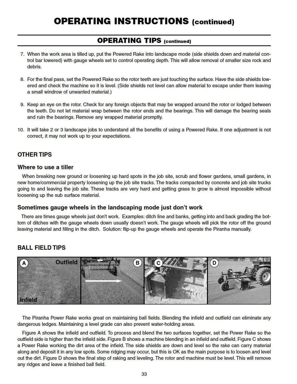
33 OPERATION Finish Grading OPERATING INSTRUCTIONS (continued) The rake is adjusted until the teeth of the toothed rotor are barely touching the soil. Prime mover speed can be increased for this operation, the idea being to collect material from the high spots and leave it in the low areas. Final Grade: Set the rotor teeth so they are just touching the surface. This will collect the small rock and debris. This is where the raking action occurs not the processing action. (see note) NOTICE: Raking action is the setting where only the teeth are just touching the ground. In this setting, the operator needs to concentrate on driving straight, blending each and every raking pass together. In the raking mode, you should have NO material going over the rotor. The right finish is achieved through a combination of proper soil moisture conditions, operating depth, ground speed, material control bar opening and rotor angle. As you gain experience, your Powered Raking capabilities will improve. Thatching Existing Grass Areas This procedure is done with the 3 pt. top link in the lock-out position (top hole) so accurate depth control can be maintained. The top link should be lengthened to support the rake on the gauge wheels and toothed roller raised so teeth are just grazing the surface. Select and maintain a slow travel speed. OPERATING TIPS 1. Walk around the work site, check for underground obstacles like electrical and utilities, property line stakes, large rocks, buried concrete or ledge rock. Plan on where to deposit unwanted debris and material. 2. If you are inexperienced with operating a Powered Rake, find an area that is dry and allows you to make at least a 50 ft. run. 3. Begin traveling forward while gently lowering the running Power Rake to the ground. Make slight changes and observe the result. 4. The Powered Rake should be set to operate level. Make adjustments with the power unit or gauge wheels to achieve this. 5. Hard Packed Soil After the first pass, you may notice hard spots in the work area. Put the Piranha Power Rake in a tilling mode by raising the side shields and the gauge wheels. Then make several passes over the hard trouble spots. Tracks and ruts made by construction equipment need to be taken care of to achieve a proper seedbed. 6. If the work area has considerable tall grass or green material you may need to raise the material control bar so material can flow through. You may also be required to mow or use a rototiller before using the Powered Rake. If you mow, the area will process better if you let the green material dry out first. 32
34
35 OPERATING INSTRUCTIONS (continued) OPERATING TIPS (continued) IMPORTANT Avoid Power Rake damage. DO NOT ram into piles of debris. Use a blade or loader bucket for this type of job. LARGE AREAS When raking a large area, make a path down the middle and rake to both sides. This reduces the amount of debris the rake must move to one side. If you have windrows of rocks and debris, set the rake in the straight position (no angle) and place the side shields down.you can straddle the windrow, and gather the rocks and debris into piles, which can then be easily picked up with a loader bucket. HEAVY DEBRIS Travel slowly 1 to 2 mph. Rake a path less than the full width of the angled Power Rake. Decrease forward speed if debris becomes very heavy. GENERAL DRIVEWAY AND ROAD MAINTENANCE Gravel processing and road maintenance may be done with a Piranha Power Rake. Potholes can be a real problem. Just filling them in usually does not work. The rim of the pothole needs to be cut out. The Power Rake rotor can cut and grind the material leaving a level surface. A common problem with gravel driveways/roads is that the rock type gravel becomes packed down leaving the fines or sand. The usual repair is to bring in more gravel. By processing the existing gravel, the Power Rake will bring the rock part of the gravel back to the surface and many times there is no need to bring in more gravel. If more gravel is needed, the Power Rake can spread it evenly. Set the material bar so more material will flow over the rotor. Adjust the material bar for the amount you want to put down. MATERIAL BAR: Set the material bar to regulate the amount of material needed to flow through the Power Rake. GAUGE WHEELS: Most driveways/roads need a pitch for proper drainage. This may be accomplished by changing the spacers on the gauge wheel spindles. (Make one side higher or lower than the other). SIDE SHIELDS: Having the side shields down will collect and hold material and help carry it to fill in low spots. Removing or flipping-up the ditch side end shield will let the rotor teeth have more contact with the base surface. NOTE: Removing or flipping-up the side shields will prevent them from being damaged if you make contact with ledge rock, roots or other sub-surface objects 34
36 OPERATING INSTRUCTIONS (continued) TRANSPORTING WHEN TRAVELLING TO ANOTHER WORK AREA: Keep the Powered Rake low to the ground when transporting or operating the machine. Be sure to reduce tractor ground speed when turning or traveling over rough terrain. Do not operate PTO during transport. Pick the most level route possible when transporting across fields. Avoid edges of ditches or gullies and steep hillsides. Allow for additional length and width of prime mover and attachment when turning. TRANSPORTING UNIT ON TRUCK OR TRAILER: The unit may be lifted and moved by a crane. Disconnect power rake from tractor. Secure crane hook to nylon strap or lift lug. Place strap near center of machine. (Chain case side of center.) Lift the entire unit off the ground and carefully load on truck or trailer. Use extra care when loading or unloading unit onto trailer or truck. Tie unit down with straps or chains over the main frame and mounting plate. Be careful not to damage hydraulic hoses, PTO driveline, or angle linkages when securing unit. Gauge wheels may be fastened in the up position to take less room on the trailer. POWER RAKE STORAGE Clean all debris from the machine and power wash. Grease all grease fittings. Lower side shields and pin to improve stability of machine. Storage location should be level and have a solid surface to make hitching and unhitching easy. Remove drive chain, clean and then soak chain in oil for 24 hours, reinstall on machine. Make sure there is no water in the chain case when machine is put into storage. In cold/freezing climates, water can freeze and damage chain case. Disconnect hydraulic hoses from prime mover. Install dust plugs or couple hoses together, as appropriate. Disconnect PTO driveline from tractor. Collapse PTO driveshaft as far as possible and store it to prevent ground contact. Lower the parking stand and pin in place. Lower rake to ground. Disconnect rake from tractor 3 pt. hitch and carefully drive tractor away. Keep children and bystanders away from storage area. Check over the machine for worn or damage parts/components. Order replacement parts. 35

37

38
39 OWNER SERVICE (continued) CHECK HYDRAULIC SYSTEM FOR LEAKS. SEE PROCEDURE BELOW. Never use your hands to locate a hydraulic leak on attachments. Use a small piece of cardboard or wood. Hydraulic fluid escaping under pressure can penetrate the skin. Openings in the skin and minor cuts are susceptible to infection from hydraulic fluid. If injured by escaping hydraulic fluid, see a doctor at once. Gangrene and death can result. Without immediate medical treatment, serious infection and reactions can occur. SLIP CLUTCH MAINTENANCE The Powered Rake drive components are protected from shock loads by a friction slip clutch. The clutch must be capable of slippage during operation to protect the gearbox, driveline, and other drive train parts. Friction clutches should be "run-in" prior to initial operation and after long periods of inactivity to remove any oxidation or rust that may have accumulated on the friction surfaces. Repeat "run-in" instructions at the beginning of each season and when moisture and/or condensation seizes the inner friction plates. The clutch should be checked during the first hour of operation and periodically each week. With a pencil or scribe, mark the clutch plates and the friction disc (make a straight line across the edge of them). If the clutch has slipped, the scribed markings will have all changes position; slippage has not occurred if any of the two marks on the friction disk and plate are still aligned. CHECKING THE CLUTCH Make sure tractor engine is turned off and key is removed. Remove driveline from tractor PTO. Loosen the eight bolts to remove all tension from springs (until spring can be turned with fingers). Hold clutch hub solid and turn shaft to make sure clutch slips. If clutch does not slip freely, disassemble and clean the faces of clutch plate, yoke and plate, and clutch hub. If clutch slips, then retighten the springs using the chart on next page as a guide. CAUTION! Slip clutches that have been in use or have slipped for only two or three seconds during run-in may be too hot to touch. Allow a hot clutch to cool before working on it. CLUTCH RUN-IN 1. Loosen the eight bolts to remove all tension from springs (until springs can be turned with fingers). 2. Place the rotor on the ground. Make sure the area is clear of all bystanders and machine is safe to operate. 3. Start tractor and engage PTO drive for 2-3 seconds to permit slippage of the clutch surfaces. Disengage PTO, then re-engage a second time for 2-3 seconds. Disengage PTO, shut off tractor and remove key. Wait for all components to stop before dismounting from tractor. 4. Inspect clutch and ensure that the scribed markings made on the clutch plates have all changed position. Slippage has not occurred if any two marks on the friction disk and plate are still aligned. A clutch that has not slipped must be disassembled to separate the friction disk plates. 5. Allow the clutch to cool to ambient temperature before adjusting the springs to their correct length and clutch pressure. 38
 5 foot 1.37\" (35mm) 6 foot 1.")

40 CLUTCH SPRING ADJUSTMENT OWNER SERVICE (continued) The same PTO driveline and slip clutch are used on several different width models of powered landscape rakes. Depending on the width of your powered rake set the clutch spring length according to the following chart. WIDTH OF POWERED RAKE CLUTCH SPRING COMPRESSED LENGTH (H) 5 foot 1.37" (35mm) 6 foot 1.34" (34mm) 7 foot 1.32" (33.5mm) 8 foot 1.30" (33mm) NOTE: The original uncompressed spring length (free length) is 1.45 inches (36.8mm). The above chart is an approximate guide to setting the clutch. You may have to make minor corrections to have the clutch set correctly for your application. NOTE: When making clutch spring pressure adjustments, it is important that you make minor adjustments (1/3 of a turn or two wrench flats on a nut). Then try the rake. If further adjustments are necessary, do so in 1/3 turn increments. Adjust only to provide sufficient torque to prevent slippage under normal conditions. Occasional slippage is normal for drive train protection. Remember, a clutch that won't slip is NO protection. CLUTCH WEAR Inspect all parts for excessive wear and condition. Clean all parts that do not require replacement. The original disk thickness is 1/8" and should be replaced if the thickness becomes less that 3/32". If the clutch has slipped to the point of "smoking", the friction disks may be damaged and should be replaced. Reassemble each friction disk next to the metal plate it was separated from. HYDRAULIC HOSES & COUPLERS (Hydraulic Angle Kit) Relieve pressure before uncoupling hydraulic couplers. Not relieving pressure could make recoupling difficult or impossible. Keep hydraulic fittings off the ground to prevent damage and collecting dirt and foreign material. Cleaning off hydraulic tips before coupling is very important so you don t contaminate the hydraulics with dirt. Even though hydraulic system are turned off, there still could be hydraulic pressure in the system that could spray out when coupling and uncoupling. Always wear safety glasses and be careful. If any damage occurs to hydraulic hoses, REPLACE IMMEDIATELY! WRONG Use nylon ties to fasten hydraulic hose and keep it in place. 39

. Lift the unit slightly off the ground (or raise the unit with a hoist).")
41 OWNER SERVICE (continued) CHECKING THE DRIVE CHAIN, SPRING TENSION AND CLEANING THE CHAIN CASE The PTC Series of Power Rakes has a single #80 drive chain. The PTHD Series has a double #80 drive chain. During the initial break-in period, the drive chain needs to be checked. The chain tension may require adjustment. The chain case will also need to be checked for oil and dirt accumulation and if required, cleaned. These checks should be made weekly. To perform this check, the power rake needs to be connected to the power unit (tractor or skid steer). Lift the unit slightly off the ground (or raise the unit with a hoist). Remove the chain case cover by removing the six (6) 3/8" bolts on the two sides of the cover. Guard is removed to show mechanical function. NOTE: Replacement chain should be only high quality original equipment chain for longer life. NOTE: Always shut the power unit off, remove ignition key, and place blocking under the rake before doing the drive chain check. Check the chain for tension after removing the case cover. The chain should be snug (no loose or free movement). If the chain has some looseness you might adjust the spring or remove a half link from the chain. If you can connect the spring to another hole position to put more spring tension on the chain this would be your first option. The second option would be to check the tension spring for stretching. If the spring is stretched out, replace the spring by removing cotter pins and removing the washer. Replace the spring with a new one and reassemble. Third option would be to remove a half link from the chain. Release the tension on the chain by unhooking the spring. Remove the master link and then the half link. If there is no half link, then remove a full link and add a half link to the chain assembly. Reinstall the master link, reattach the spring and reassemble the chain case cover. NOTE: Clean the inside of the chain case and cover before putting the cover back on. NOTE: The chain case and cover have strips of "weather stripping" installed to keep out dust and dirt. If the weather strips are damaged, replace with new weather strips from your local hardware store (weather stripping has an adhesive back clean the edges of the chain case before installing). 40
BEFORE YOU START!! Read the safety messages on the implement as shown in your manual. Observe the rules of safety and common sense!
 To the Owner/Operator/Dealer All implements with moving parts are potentially hazardous. There is no substitute for a cautious, safe-minded operator who recognizes the potential hazards and follows reasonable
OPERATION MANUAL DBW Bale Wagon DFW Feeder Wagon
 OPERATION MANUAL DBW Bale Wagon DFW Feeder Wagon To the Owner/Operator/Dealer All implements with moving parts are potentially hazardous. There is no substitute for a cautious, safe-minded operator who
Operator s Manual. Go Galvanized! YOU'RE ALWAYS AHEAD...WITH A MODERN BEHIND.
 fall 2010 3pt & quick attach Bale spears & 3pt bale carrier Operator s Manual YOU'RE ALWAYS AHEAD...WITH A MODERN BEHIND. 318-1006-i 318-1005-i 020-1500 020-1502 P.O. Box 790 Beaumont, Tx 77704 409.833.2665
QUICK ATTACH SNOW PUSHER OPERATION AND ASSEMBLY MANUAL
 QUICK ATTACH SNOW PUSHER OPERATION AND ASSEMBLY MANUAL INTRODUCTION TO THE OWNER: Read this manual before operating your equipment. Keep this manual handy for ready reference. Require all operators to
Broadcast Seeder/Spreader
 OWNER S/ OPERATOR S MANUAL MODEL NO. s CS-694 CS-1094 CSP-1094 CAUTION For Safe Operation Read Rules And Instructions Carefully SINO LEEINGLES, PIDA AYUDA A AIGUIEN QUE SI LO LEA PARA QUE LE TRADUZCA LAS
3 PT. HITCH BALE SPEARS
 OWNER S/ OPERATOR S MANUAL BS-1506 MODEL NO. s BS-1506 BS-1520 BSF-1525 BS-1520 BSF-1525 CAUTION For Safe Operation Read Rules And Instructions Carefully 3 PT. HITCH BALE SPEARS SINO LEEINGLES, PIDA AYUDA
3 PT. BOX SCRAPER CAUTION OWNER S/ OPERATOR S MANUAL. MODEL NO. s SBX-4 SBX-5 SBX-5 1 /2 SBX-6 SBX-7 SBX-8 CAUTION
 OWNER S/ OPERATOR S MANUAL MODEL NO. s SBX-4 SBX-5 SBX-5 1 /2 SBX-6 SBX-7 SBX-8 CAUTION For Safe Operation Read Rules And Instructions Carefully 3 PT. BOX SCRAPER SINO LEEINGLES, PIDA AYUDA A AIGUIEN QUE
CAUTION. IMPORTANT SAFETY INFORMATION Please stay alert for these signs.
 For safe operation, read rules and instructions carefully. The following safety precautions should be thoroughly understood before attempting to begin the assembly of this machine. 1. Select an area for
FORGED REPLACEMENT BALE SPEARS
 OWNER S/ OPERATOR S MANUAL PART NO. s 831180 1800 Lb. Capacity (with Sleeve) 831190 2200 Lb. Capacity (with Sleeve) 832215 2200 Lb. Capacity (with Cast Steel Socket) 832214 31.5 Spear (with Cast Steel
HAY HANDLER / UNROLLER
 OWNER S/ OPERATOR S MANUAL MODEL NO. HHU-2045 For Safe Operation Read Rules And Instructions Carefully HAY HANDLER / UNROLLER SI NO LEEINGLES, PIDA AYUDA A AIGUIEN QUE SI LO LEA PARA QUE LE TRADUZCA LAS
W & A 12 ROW TOP LEVELING STACKER LEVEL BANDER
 W & A 12 ROW TOP LEVELING STACKER LEVEL BANDER NO. 3640 OPERATOR S MANUAL TO THE OWNER: Congratulations on your purchase of a new W & A Top Leveling Stacker Level Bander. Your selection is an indication
Powered Rakes SI NO LEEINGLES, PIDA AYUDA A AIGUIEN QUE SI LO LEA PARA QUE LE TRADUZCA LAS MEDIDAS DE SEGURIDAD.
 OWNER S/ OPERATOR S MANUAL MODEL NO. s PXS-305 PXS-405 PXS-410 PXS-510 PXS-610 CAUTION For Safe Operation Read Rules And Instructions Carefully Compact/ Mini Skid Steer Powered Rakes SI NO LEEINGLES, PIDA
DURABILT INDUSTRIES, LLC
 DURABILT INDUSTRIES, LLC Pocahontas, AR 72455 Phone: 870-892-4501 www.durabiltindustries.com 1 To the Owner/Operator/Dealer All implements with moving parts are potentially hazardous. There is no substitute
W & A 12 ROW TOP LEVELING STACKER LEVEL BANDER
 W & A 12 ROW TOP LEVELING STACKER LEVEL BANDER NO. 3640 OPERATOR S MANUAL TO THE OWNER: Congratulations on your purchase of a new W & A Top Leveling Stacker Level Bander. Your selection is an indication
TL SERIES ADJUSTABLE OFFSET TILLER
 R L S E S 995 OPERATION & PARTS MANUAL Please read these instructions carefully before using! Always grease all fittings and be sure to always check and fill with oil before operating! Retain this manual
ROLLER COMPACTORS OPERATOR S MANUAL MODELS SC6016, SC6016-3PT, SC6020 SC7220-3PT, SC7220, SC8420, SC9620
 ROLLER COMPACTORS OPERATOR S MANUAL MODELS SC6016, SC6016-3PT, SC6020 SC7220-3PT, SC7220, SC8420, SC9620 MANUFACTURER'S LIMITED WARRANTY Manufacturer warrants to original Purchaser that its product is
POST HOLE DIGGER 915-PHD-06-SC, 915-PHD-09-SC & 915-PHD-12-SC
 TAYLOR PITTSBURGH MFG., INC. PO BOX1200 WINFIELD, AL 35594 205-487-3202 POST HOLE DIGGER 915-PHD-06-SC, 915-PHD-09-SC & 915-PHD-12-SC OWNER S MANUAL TO THE PURCHASER This manual contains valuable information
UNIVERSAL LOADER FORK and SKID STEER PALLET FORK
 OWNER S/ OPERATOR S MANUAL MODEL NO. s ULF-246 SSPF-20 CAUTION For Safe Operation Read Rules And Instructions Carefully UNIVERSAL LOADER FORK and SKID STEER PALLET FORK SINO LEEINGLES, PIDA AYUDA A AIGUIEN
LP1207 LP1208 LP1210 LAND PLANES LP12_5TL15788_06/10
 LP1207 LP1208 LP1210 O P E R A T O R ' S M A N U A L LAND PLANES LP12_5TL15788_06/10 TO THE DEALER: Assembly and proper installation of this product is the responsibility of the Frontier dealer. Read manual
BEFCO. Operator s Manual POST HOLE DIGGER ACCESSORIES DOWN FORCE KIT. PHD-002 (fits models MOLE 300 & 400) PHD-005 (fits model MOLE 200) HOOKUP STAND
 PHD-005 (fits model MOLE 200) HOOKUP STAND") BEFCO Operator s Manual POST HOLE DIGGER ACCESSORIES DOWN FORCE KIT PHD-00 (fits models MOLE 300 & 400) PHD-005 (fits model MOLE 00) HOOKUP STAND 009-985 (fits models MOLE 00, 00, 300 & 400) POSITIONING
BEFCO Operator s Manual POST HOLE DIGGER ACCESSORIES DOWN FORCE KIT PHD-00 (fits models MOLE 300 & 400) PHD-005 (fits model MOLE 00) HOOKUP STAND 009-985 (fits models MOLE 00, 00, 300 & 400) POSITIONING
DURABILT INDUSTRIES, LLC
 DURABILT INDUSTRIES, LLC Pocahontas, AR 72455 Phone: 870-892-4501 www.durabiltindustries.com 1 To the Owner/Operator/Dealer All implements with moving parts are potentially hazardous. There is no substitute
LOADER BUCKET ATTACHMENT(S) (CLAMP-ON)
 (CLAMP-ON)") OWNER S MANUAL MODEL NO.s BBS-1560 BBSF-2535 BBSF-1565 T-1500 CAUTION For Operation Read Rules And Instructions Carefully Safety Instructions Assembly & Mounting Operating Instructions BBS-1560 Maintenace
OWNER S MANUAL MODEL NO.s BBS-1560 BBSF-2535 BBSF-1565 T-1500 CAUTION For Operation Read Rules And Instructions Carefully Safety Instructions Assembly & Mounting Operating Instructions BBS-1560 Maintenace
W & A RIGID PULVAMIZER MODEL NO & 3544 OPERATOR S MANUAL
 W & A RIGID PULVAMIZER MODEL NO. 3504 & 3544 OPERATOR S MANUAL TO THE OWNER: Congratulations on your purchase of a new W & A Rigid Pulvamizer. Your selection is an indication of your awareness of the need
DURABILT INDUSTRIES, LLC
 DURABILT INDUSTRIES, LLC Pocahontas, AR 72455 Phone: 870-892-4501 www.durabiltindustries.com 1 To the Owner/Operator/Dealer All implements with moving parts are potentially hazardous. There is no substitute
Operator and Parts Manual. Rotary Sweep 3-PT. Mounted PTO Driven. Models W6032, W7232 & W8432
 Operator and Parts Manual Rotary Sweep 3-PT. Mounted PTO Driven Models W6032, W7232 & W8432 062010 911135 2 Table of contents 3-pt Mounted PTO Driven Rotary Sweep Table of Contents Introduction... 5 Safety...
LAND GRADER 5 & 6 OWNER S OPERATION & PARTS MANUAL. Bad Boy, Inc. 102 Industrial Drive Batesville, Arkansas 72501
 5 & 6 LAND GRADER OWNER S OPERATION & PARTS MANUAL For additional information, please see us at www.badboymowers.com Bad Boy, Inc. 0 Industrial Drive Batesville, Arkansas 750 08-6 TO THE DEALER Assembly,
BALE SPEAR ATTACHMENTS for John Deere Loaders
 OWNER S/ OPERATOR S MANUAL MODEL NO. s JDBS-412 JDBS-423 JDBS-434 JDBS-433 JDBS-612 JDBS-623 JDBS-634 JDBS-633 JDBS-412 JDBS-612 JDBS-423 JDBS-634 CAUTION For Safe Operation Read Rules And Instructions
2 PT. HITCH to 3 PT. HITCH ADAPTER KITS
 OWNER S/ OPERATOR S MANUAL MODEL NO. s HK - 126, 132 226 326 426, 432 526 626, 632 726, 732 826 1026, 1032 1126, 1132 CAUTION For Safe Operation Read Rules And Instructions Carefully HK-126 mounted on
3 Pt. Rear Mounted Blade
 OWNER S/ OPERATOR S MANUAL MODEL NO. s EB-6-3 EB-7-3 CAUTION For Safe Operation Read Rules And Instructions Carefully SINO LEEINGLES, PIDA AYUDA A AIGUIEN QUE SI LO LEA PARA QUE LE TRADUZCA LAS MEDIDAS
Operating Instructions CAUTION
 OWNER S/ OPERATOR S MANUAL MODEL NO. s FSO-906 FLSO-907 SSSO-908 ROUND BALE FEEDER FSO-906 SSSO-908 Pat. No. 4,084,707 CAUTION For Safe Operation Read Rules And Instructions Carefully SINO LEEINGLES, PIDA
STANDARD DUTY 3-PT. MOUNTED ROTARY CUTTER
 OWNER S/ OPERATOR S MANUAL MODEL NO s SDM40-48 SDM40-60 SDM40-72 CAUTION For Safe Operation Read Rules And Instructions Carefully SINO LEEINGLES, PIDA AYUDA A AIGUIEN QUE SI LO LEA PARA QUE LE TRADUZCA
3 PT. REAR FINISHING MOWER For Cat. I 3-Pt. Hitch Tractors up to 35 HP CAUTION
 OWNER S MANUAL MODEL NO s EM/2 60 EM/2 72 CAUTION For Safe Operation Read Rules And Instructions Carefully SINO LEEINGLES, PIDA AYUDA A AIGUIEN QUE SI LO LEA PARA QUE LE TRADUZCA LAS MEDIDAS DE SEGURIDAD.
GLPF-5548 FOR SKID STEER
 OWNER S/ OPERATOR S MANUAL MODEL NO. s PF-448 SSPF-442 SSPF-448 JDPF-5442 JDPF-5448 JDPF-6748 GLPF-442 GLPF-448 GLPF-5548 CAUTION For Safe Operation Read Rules And Instructions Carefully SINO LEEINGLES,
OPERATORS MANUAL FOR KAFURTER ROTARY TOPPERS MODELS: TP110, TP140, TP160, TP170
 OPERATORS MANUAL FOR KAFURTER ROTARY TOPPERS MODELS: TP110, TP140, TP160, TP170 SAFETY WARNING: Do not use or operate this this manual and assembly instructions (where applicable) has been read and understood.
UNIVERSAL LOADER FORK and SKID STEER PALLET FORK
 OWNER S/ OPERATOR S MANUAL MODEL NO. s ULF-355 ULF-346 VLF-7655 VLF-7646 SSPF-40 CAUTION For Safe Operation Read Rules And Instructions Carefully UNIVERSAL LOADER FORK and SKID STEER PALLET FORK SINO LEEINGLES,
3 PT. LANDSCAPE RAKE CAUTION OWNER S/ OPERATOR S MANUAL. MODEL NO. s CAUTION DCR-4 MCR-6 DCR-5 MCR-7 LRHD-6 LRHD-7 LRHD-8 LRHD-7
 OWNER S/ OPERATOR S MANUAL DCR-4 MODEL NO. s DCR-4 MCR-6 DCR-5 MCR-7 LRHD-6 LRHD-7 LRHD-8 LRHD-7 (Rakes shown with optional gauge wheels) CAUTION For Safe Operation Read Rules And Instructions Carefully
BOX BLADES BB3272 BB3284 BB3296 BB32_5TL15288_07/10
 O P E R A T O R ' S M A N U A L BOX BLADES BB3272 BB3284 BB3296 BB32_5TL15288_07/10 TO THE DEALER: Assembly and proper installation of this product is the responsibility of the Frontier dealer. Read manual
3 PT. REAR FINISHING MOWER
 OWNER S/ OPERATOR S MANUAL MODEL NO s FM 560 FM 572 CAUTION For Safe Operation Read Rules And Instructions Carefully 3 PT. REAR FINISHING MOWER For Cat. I 3-Pt. Hitch Tractors up to 35 HP SINO LEEINGLES,
3 PT. LANDSCAPE RAKE CAUTION OWNER S/ OPERATOR S MANUAL. MODEL NO. s CAUTION DCR-4 MCR-6 DCR-5 MCR-7 ULR-6 ULR-7 ULR-8
 OWNER S/ OPERATOR S MANUAL MODEL s DCR-4 MCR-6 DCR-5 MCR-7 ULR-6 ULR-7 ULR-8 CAUTION For Safe Operation Read Rules And Instructions Carefully (Rakes shown with optional gauge wheels) 3 PT. LANDSCAPE RAKE
FLIP-OVER SPIKE-TOOTH HARROW
 OWNER S/ OPERATOR S MANUAL MODEL NO. FOH-5 CAUTION For Safe Operation Read Rules And Instructions Carefully SINO LEEINGLES, PIDA AYUDA A AIGUIEN QUE SI LO LEA PARA QUE LE TRADUZCA LAS MEDIDAS DE SEGURIDAD.
OPE R AT O R S MANU A L QUICK-HITCH ADAPTER. 5BP (Field conversion kit)
") OPE R AT O R S MANU A L 5BP006750 (Field conversion kit) Manual 5BP97378B Date 06/8/05 SAFETY Take note! This safety alert symbol found throughout this manual is used to call your attention to instructions
OPE R AT O R S MANU A L 5BP006750 (Field conversion kit) Manual 5BP97378B Date 06/8/05 SAFETY Take note! This safety alert symbol found throughout this manual is used to call your attention to instructions
610 BUSHEL MANURE SPREADER
 610 BUSHEL MANURE SPREADER RODA MANUFACTURING 1008 LOCUST ST. HULL, IA. 51239 Art s-way Manufacturing 712-439-2366 Co., Inc. Hwy 9 West - PO Box 288 WWW.RODAMFG.COM Armstrong, IA. 50514 U.S.A 2 INTRODUCTION
Grapple Rake for Compact Tractor Front Loaders
 OWNER S/ OPERATOR S MANUAL MODEL NO. s FLGR-4062 FLGR-4062S CAUTION For Safe Operation Read Rules And Instructions Carefully Grapple Rake for Compact Tractor Front Loaders SINO LEEINGLES, PIDA AYUDA A
3 PT. MIXER OWNER S/ OPERATOR S MANUAL MODEL NO. 580C CAUTION. For Safe Operation Read Rules And Instructions Carefully
 OWNER S/ OPERATOR S MANUAL MODEL NO. 580C CAUTION For Safe Operation Read Rules And Instructions Carefully 3 PT. MIXER SINO LEEINGLES, PIDA AYUDA A AIGUIEN QUE SI LO LEA PARA QUE LE TRADUZCA LAS MEDIDAS
AG PRODUCTS, LTD. YOU RE ALWAYS AHEAD... WITH A MODERN BEHIND.
 SUMMER 2016 BADGER DISC HARROW Operator s Manual 011-1156 011-1166 001-1501 001-1501-1 011-1167 001-1501-2 001-1501-3 011-1176 001-1501-4 011-1177 MODERN AG PRODUCTS, LTD. YOU RE ALWAYS AHEAD... WITH A
3-Pt. Box Scraper. Owner s Manual
 3-Pt. Box Scraper Owner s Manual WARNING: Read carefully and understand all ASSEMBLY AND OPERATION INSTRUCTIONS before operating. Failure to follow the safety rules and other basic safety precautions may
Operator s Manual. Go Galvanized! YOU'RE ALWAYS AHEAD...WITH A MODERN BEHIND.
 fall 2009 Rotary Tiller Operator s Manual YOU'RE ALWAYS AHEAD...WITH A MODERN BEHIND. 010-0127-1 010-0128-2 010-0130-3 P.O. Box 790 Beaumont, Tx 77704 409.833.2665 1.800.231.8198 Fax: 409.726.8333 www.modernusa.com
3 PT. MIXER OWNER S MANUAL CAUTION MODEL NO. 580 CAUTION. For Safe Operation Read Rules And Instructions Carefully
 OWNER S MANUAL MODEL NO. 580 CAUTION For Safe Operation Read Rules And Instructions Carefully SINO LEEINGLES, PIDA AYUDA A AIGUIEN QUE SI LO LEA PARA QUE LE TRADUZCA LAS MEDIDAS DE SEGURIDAD. 3 PT. MIXER
OWNER S and OPERATOR S MANUAL for ROTARY MOWERS. For all model rotary mowers manufactured by Pegasus Industries Inc including RM4; RM5; HRM5 and HRM6
 SERVICE GEARBOX LUBRICATION Rotary mower gearboxes have two plugs in the rear. The upper plug is the fill plug. The lower plug is the check plug. Gearboxes should never be filled with oil higher than the
POST HOLE DIGGER OWNER S/ OPERATOR S MANUAL MODEL NO CAUTION For Safe Operation Read Rules And Instructions Carefully
 OWNER S/ OPERATOR S MANUAL MODEL NO. 500 CAUTION For Safe Operation Read Rules And Instructions Carefully STANDARD DUTY 3-PT. MOUNTED POST HOLE DIGGER SI NO LEEINGLES, PIDA AYUDA A AIGUIEN QUE SI LO LEA
POWER BOX RAKE MODEL T-5 OPERATOR S MANUAL
 POWER BOX RAKE MODEL T-5 OPERATOR S MANUAL DATE PURCHASED SERIAL NUMBER INTRODUCTION GLENMAC, INC., based in Jamestown, North Dakota, along with your authorized Harley dealer, are proud that you chose
BEFCO. Operator s Manual BABY HOP & HOP FERTILIZER SPREADERS ACCESSORIES SIDE ROW DISCHARGE. AA4-120 (fits models Hop 209 & 212) DEFLECTOR
 DEFLECTOR") BEFCO Operator s Manual BABY HOP & HOP FERTILIZER SPREADERS ACCESSORIES SIDE ROW DISCHARGE AA-0 (fits models Hop 09 & ) DEFLECTOR AA-0 (fits models Baby Hop 0 & 06) 009-95 (fits models Hop 0 & 06) 009-968
BEFCO Operator s Manual BABY HOP & HOP FERTILIZER SPREADERS ACCESSORIES SIDE ROW DISCHARGE AA-0 (fits models Hop 09 & ) DEFLECTOR AA-0 (fits models Baby Hop 0 & 06) 009-95 (fits models Hop 0 & 06) 009-968
OWNER S/ OPERATOR S MANUAL
 Quick Attach Bucket Clamp-Ons Safety instructions Tractor Preparation Operating Instructions Assembly & Mounting Maintenance Repair Parts OWNER S/ OPERATOR S MANUAL Universal Quick Attach 2 Receiver w/
ROTARY TILLER. Operation, Service & Parts Manual For "AS" Series. FORM: ASTillerBook.QXD
 ROTARY TILLER Operation, Service & Parts Manual For "AS" Series FORM: ASTillerBook.QXD April 2002 TABLE OF CONTENTS Preparation......................................1 Assembly Instructions.............................2
DISK HARROWS DH1166 DH1176 DH1180 DH11_5TL15191_5/08
 O P E R A T O R ' S M A N U A L DISK HARROWS DH1166 DH1176 DH1180 DH11_5TL15191_5/08 TO THE DEALER: Assembly and proper installation of this product is the responsibility of the Frontier dealer. Read manual
LP1160 LP1172 LP1184 LP1196 LAND PLANES LP11_5TL15614_05/08
 LP1160 LP1172 LP1184 LP1196 O P E R A T O R ' S M A N U A L LAND PLANES LP11_5TL15614_05/08 TO THE DEALER: Assembly and proper installation of this product is the responsibility of the Frontier dealer.
Operator s Manual. Ground Drive Fertilizer Spreader PTS PTS-160
 Operator s Manual Ground Drive Fertilizer Spreader PTS-100 - PTS-160 Publication #: April 2009 TABLE OF CONTENTS INTRODUCTION... 1 SAFETY... 1 SAFETY SIGNAL WORDS... 2 GENERAL SAFETY GUIDELINES... 2 SAFETY
PALLET FORK for COMPACT TRACTOR FRONT LOADERS and MINI SKID STEER UNITS
 OWNER S/ OPERATOR S MANUAL MODEL NO. s MPF-1200 MPF-1200B/G MPF-2000 MPF-2000B/G SSPF-1236 SSPF-242 JDPF-1236 JDPF-2000 FLPF-2000 CAUTION For Safe Operation Read Rules And Instructions Carefully SSPF-242
WARNING this attachments capacity changes depending on the Skid Steer Loader it is hooked up to. CAPACITY AT 24 LOAD CENTER
 SKID STEER FORKLIFT ATTACHMENT Any piece of equipment can be dangerous if not operated properly. YOU are responsible for the safe operation of this equipment. The operator must carefully read and follow
3-Pt. PTO Post Hole Digger
 3-Pt. PTO Post Hole Digger Owner s Manual WARNING: Read carefully and understand all ASSEMBLY AND OPERATION INSTRUCTIONS before operating. Failure to follow the safety rules and other basic safety precautions
3-Pt. Landscape Rake
 3-Pt. Landscape Rake Owner s Manual WARNING: Read carefully and understand all ASSEMBLY AND OPERATION INSTRUCTIONS before operating. Failure to follow the safety rules and other basic safety precautions
Walker Loader Bucket OPERATOR S AND PARTS MANUAL
 Walker Loader Bucket OPERATOR S AND PARTS MANUAL Please Read and Save These Instructions For Safety, Read all Safety and Operation Instructions Prior To Operating Machine P/N 6690 TABLE OF CONTENTS Introduction
OPERATOR S & PARTS MANUAL
 OPERATOR S & PARTS MANUAL MODEL T5 POWER BOX RAKE SERIAL NUMBER: MODEL NUMBER: 800-437-9779 www.paladinbrands.com MANUAL NUMBER: PART NUMBER: PO Box 230, Jamestown, ND 58402-0230, United States of America
Mulcher Operators Manual
 Mulcher Operators Manual Skid Pro Attachments PO Box 982 Alexandria, MN 56308 October 2015 1 2 Contents 1. Introduction And Warranty... 4 1.1 Introduction... 4 1.2 Warranty... 4 2. Component Identification...
Two-Stage Snow Blower For 4WD Pick Up Trucks. Operator s Manual
 Two-Stage Snow Blower For 4WD Pick Up Trucks Operator s Manual Distrubuted by: Metal Fabricating LLC P.O. Box 831 Brodheadsville, PA 18322 Phone: 570-992-9989 SnowVac.com WARRANTY POLICY Metal Fabricating
3-Pt. Boom Pole. Owner s Manual
 3-Pt. Boom Pole Owner s Manual WARNING: Read carefully and understand all ASSEMBLY AND OPERATION INSTRUCTIONS before operating. Failure to follow the safety rules and other basic safety precautions may
PALLET FORK FOR SKID STEER TRACTOR FRONT LOADERS
 OWNER S/ OPERATOR S MANUAL MODEL NO. s PF-448 SSPF-3748 SSPF-3755 SSPF-442 SSPF-448 SSPF-5548 GLPF-442 GLPF-448 GLPF-5548 JDPF-5442 JDPF-5448 JDPF-6748 JDPF-H48048 JDPF-H48060 PALLET FORK FOR SKID STEER
THANK YOU FOR PURCHASING THIS PRODUCT
 Tillage Discs Sub Compact, Medium, & Heavy Duty Hardware Kit 80900240 THANK YOU FOR PURCHASING THIS PRODUCT Congratulations on your purchase. Behlen Country has been in the business of providing quality
THANK YOU FOR PURCHASING THIS PRODUCT
 Hardware Kit Middle Buster, Sub Soiler, 80900200 Combo SC Middle Buster & Sub Soiler THANK YOU FOR PURCHASING THIS PRODUCT Congratulations on your purchase. Behlen Country has been in the business of providing
RED23305 Owner s Manual
 RED23305 Owner s Manual 5 foot, 3-Point Mounted Snow Blower 270 West Park Avenue Huron, SD 57350 866-526-5682 Serial Number: Date of Purchase: Red Devil Snow Blower See Figure 1. 1. The Red Devil Snow
Prime Attachments & Custom Fab Brush Mower Owners/Operators Manual
 Prime Attachments & Custom Fab Brush Mower Owners/Operators Manual The operator is responsible for the safe operation and maintenance of the machine. It is important that anyone who uses the machine is
MK AUGERS POWER SWING KIT ASSEMBLY & OPERATION MANUAL
 MK AUGERS POWER SWING KIT ASSEMBLY & OPERATION MANUAL Read this manual before using product. Failure to follow instructions and safety precautions can result in serious injury, death, or property damage.
Post Hole Digger. Hardware Kit STATEMENT OF POLICY CUSTOMER SERVICE CENTER ASSEMBLY, OPERATION, & MAINTENANCE INSTRUCTIONS
 Post Hole Digger Hardware Kit 80900085 THANK YOU FOR PURCHASING THIS PRODUCT Congratulations on your purchase. Behlen Country has been in the business of providing quality equipment to landowners for more
POST HOLE DIGGER. Operation, Service & Parts Manual For Models D20 & D40. FORM: D20_40DigRev.QXD
 POST HOLE DIGGER Operation, Service & Parts Manual For Models D20 & D40 FORM: D20_40DigRev.QXD September 2006 Revised August 2009 TABLE OF CONTENTS Introduction.............................1 Preparation..............................2
OPERATOR'S MANUAL Drawn Box Scraper LL1208 LL1210 LL1212 LL1 2_ 5DDP00538_5_1_09
 OPERATOR'S MANUAL Drawn Box Scraper LL1208 LL1210 LL1212 LL1 2_ 5DDP00538_5_1_09 TO THE DEALER: Assembly and proper installation of this product is the responsibility of the Frontier dealer. Read manual
Post Hole Digger. Hardware Kit STATEMENT OF POLICY CUSTOMER SERVICE CENTER ASSEMBLY, OPERATION, & MAINTENANCE INSTRUCTIONS
 Post Hole Digger Hardware Kit 80900085 THANK YOU FOR PURCHASING THIS PRODUCT Congratulations on your purchase. Behlen Country has been in the business of providing quality equipment to landowners for more
THANK YOU FOR PURCHASING THIS PRODUCT
 Grader Blades Hardware Kit 80900210 THANK YOU FOR PURCHASING THIS PRODUCT Congratulations on your purchase. Behlen Country has been in the business of providing quality equipment to landowners for more
HEAVY DUTY OFFSET DISCS
 HEAVY DUTY OFFSET DISCS Assembly/Operation/Parts Manual For GO Series Models October 2009 Form: GOoffsetdisc SECTION TABLE OF CONTENTS DESCRIPTION PAGE 1 Introduction... 1 1.1 Serial Number... 1 2 Safety...
POWER BOX RAKE MODEL T-6 OPERATOR S MANUAL
 POWER BOX RAKE MODEL T-6 OPERATOR S MANUAL DATE PURCHASED SERIAL NUMBER INTRODUCTION Glenmac Inc., along with your authorized dealer, sales person, executive and production worker, are proud that you chose
FLIP-OVER SINGLE GANG DISC FLIP-OVER 4 FT. CULTI-PACKER
 OWNER S/ OPERATOR S MANUAL MODEL NO. s FOD-16 FOC-48 FOC-48A CAUTION For Safe Operation Read Rules And Instructions Carefully FLIP-OVER SINGLE GANG DISC FLIP-OVER 4 FT. CULTI-PACKER SI NO LEEINGLES, PIDA
3 PT. HITCH ADAPTER KIT For I.H.C. Models
 OWNER S/ OPERATOR S MANUAL MODEL NO. s HK-90 HK-91 CAUTION For Safe Operation Read Rules And Instructions Carefully HK-91 3 PT. HITCH ADAPTER KIT For I.H.C. Models HK-90 Standard Cub Tractor HK-91 Cub
60in. Acreage Rake. Owner s Manual
 60in. Acreage Rake Owner s Manual WARNING: Read carefully and understand all ASSEMBLY AND OPERATION INSTRUCTIONS before operating. Failure to follow the safety rules and other basic safety precautions
84in. Driveway Drag. Owner s Manual
 84in. Driveway Drag Owner s Manual WARNING: Read carefully and understand all ASSEMBLY AND OPERATION INSTRUCTIONS before operating. Failure to follow the safety rules and other basic safety precautions
POST HOLE DIGGER CAUTION OWNER S/ OPERATOR S MANUAL MODEL NO CAUTION For Safe Operation Read Rules And Instructions Carefully
 OWNER S/ OPERATOR S MANUAL MODEL NO. 720 CAUTION For Safe Operation Read Rules And Instructions Carefully SINO LEEINGLES, PIDA AYUDA A AIGUIEN QUE SI LO LEA PARA QUE LE TRADUZCA LAS MEDIDAS DE SEGURIDAD.
3-Pt. Quick Hitch. Owner s Manual
 3-Pt. Quick Hitch Owner s Manual WARNING: Read carefully and understand all ASSEMBLY AND OPERATION INSTRUCTIONS before operating. Failure to follow the safety rules and other basic safety precautions may
THANK YOU FOR PURCHASING THIS PRODUCT
 Disc Harrows Sub Compact, Medium, & Heavy Duty Hardware Kit 80900240 THANK YOU FOR PURCHASING THIS PRODUCT Congratulations on your purchase. Behlen Country has been in the business of providing quality
POST HOLE DIGGER CAUTION OWNER S/ OPERATOR S MANUAL MODEL NO CAUTION For Safe Operation Read Rules And Instructions Carefully
 OWNER S/ OPERATOR S MANUAL MODEL NO. 500 CAUTION For Safe Operation Read Rules And Instructions Carefully SINO LEEINGLES, PIDA AYUDA A AIGUIEN QUE SI LO LEA PARA QUE LE TRADUZCA LAS MEDIDAS DE SEGURIDAD.
OPERATORS MANUAL SAFETY & WARRANTY SECTION
 OPERATORS MANUAL SAFETY & WARRANTY SECTION KMW Ltd. 198 N. Hwy 281 Great Bend, Kansas 67530 800 445-7388 Fax 620 793-6737 ïïïkâãïäç~çéêëkåçã SAFETY FIRST This symbol, the industry s Safety Alert Symbol,
ROTARY BRUSH CUTTERS THE LEADER OF THE PACK OWNER/OPERATOR SAFETY & INSTRUCTION MANUAL
 72 M-AX ROTARY BRUSH CUTTERS THE LEADER OF THE PACK OWNER/OPERATOR SAFETY & INSTRUCTION MANUAL CONTENTS Page 1. Introduction..................................2 2. Safety Instructions...........................3-4
OPERATOR S MANUAL POWER BOX RAKE MODEL M.6 STRAIGHT/ANGLE. Hydraulic Angling Non-Floating with simple battery connect
 POWER BOX RAKE MODEL M.6 STRAIGHT/ANGLE Fixed Non-Angling - forward and reverse box raking Hydraulic Angling Non-Floating with simple battery connect Manual Angling - with no electrical hook-up Hydraulic
POWER BOX RAKE MODEL S.6 OPERATOR S MANUAL
 POWER BOX RAKE MODEL S.6 OPERATOR S MANUAL DATE PURCHASED SERIAL NUMBER INTRODUCTION GLENMAC, INC., based in Jamestown, North Dakota, along with your authorized Harley dealer, are proud that you chose
Part Number Published 08/ Series Blade. 181 Series Blade
 141 SERIES 181 SERIES Published 08/15 Part Number 50076192 141 Series Blade 181 Series Blade To the Owner/Operator/Dealer All implements with moving parts are potentially hazardous. There is no substitute
OPERATOR S MANUAL PRECISION MANUFACTURING, INC. 424 N. Harding Avenue Sedalia, MO Phone (660) Fax (660)
 Fax (660)") OPERATOR S MANUAL PRECISION MANUFACTURING, INC. 424 N. Harding Avenue Sedalia, MO 65301 Phone (660) 827 6131 Fax (660) 827-7366 www.precisionmfg.com MANUAL #GR120307 TABLE OF CONTENTS INTRODUCTION... 3
OPERATOR S MANUAL PRECISION MANUFACTURING, INC. 424 N. Harding Avenue Sedalia, MO 65301 Phone (660) 827 6131 Fax (660) 827-7366 www.precisionmfg.com MANUAL #GR120307 TABLE OF CONTENTS INTRODUCTION... 3
MODELS EWR820, EWR1023, EWR1227 PULL TYPE HAY RAKES PARTS MANUAL SECTION 19
 EWR MODELS EWR820, EWR1023, EWR1227 PULL TYPE HAY RAKES Published 04/11 PARTS MANUAL SECTION 19 MATERIAL HANDLING PARTS MANUAL PARTS ORDERING GUIDE The following instructions are offered to help eliminate
OWNER S MANUAL. 3 PT. REAR BLADE For Cat. II 3 Pt. Hitch Tractors CAUTION. MODEL NO. s XHB-1096 XHB-1120 CAUTION STATEMENT OF POLICY
 OWNER S MANUAL MODEL NO. s XHB-1096 XHB-1120 CAUTION For Safe Operation Read Rules And Instructions Carefully STATEMENT OF POLICY It is the policy of Worksaver, Inc. to improve its products where it is
Operator s Manual. Go Galvanized! YOU'RE ALWAYS AHEAD...WITH A MODERN BEHIND.
 SUMMER 2008 rock & landscape rake Operator s Manual 003-7445 003-7450 003-7460 003-7440 003-7445 003-7450 YOU'RE ALWAYS AHEAD...WITH A MODERN BEHIND. P.O. Box 790 Beaumont, Tx 77704 409.833.2665 1.800.231.8198
Operator s Manual POST HOLE DIGGERS PHD100, PHD200, PHD300 & PHD400
 olqljb`= =rp^ Operator s Manual POST HOLE DIGGERS PHD00, PHD00, PHD300 & PHD00 Before you begin use of equipment, read, understand, and follow all safety instructions in this manual. The operator s manual
LANDSCAPE RAKE. Operation & Parts Manual For 20 Series LR20-60 & LR April Form: MW_LandscapeRakes
 LANDSCAPE RAKE Operation & Parts Manual For 20 Series LR20-60 & LR20-72 April 2008 Form: MW_LandscapeRakes TABLE OF CONTENTS PAGE Introduction...1 Checklists...2 General Informatioon...3 Safety Rules...4
POWER BOX RAKE MODEL M4 OPERATOR S MANUAL
 POWER BOX RAKE MODEL M4 OPERATOR S MANUAL DATE PURCHASED SERIAL NUMBER INTRODUCTION GLENMAC, INC., based in Jamestown, North Dakota, along with your authorized Harley dealer, are proud that you chose to
Talet Equipment International Ltd. Sand Kicker
 Talet Equipment International Ltd. Sand Kicker Parts & Operators Manual P.O. Box 35 Strathmore AB Canada TP K3 www.taletattachments.com sales@taletattachments.com Toll Free -888-37-5878 Fax -403-934-304