Solar PV Standard Plan Simplified Central/String Inverter Systems for One- and Two-Family Dwellings
|
|
|
- Gwen Gibbs
- 5 years ago
- Views:
Transcription

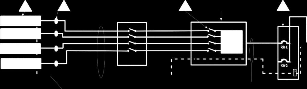
1 PV TOOLKIT DOCUMENT #3 Solar PV Standard Plan Simplified Central/String Inverter Systems for One- and Two-Family Dwellings SCOPE: Use this plan ONLY for utility-interactive central/string inverter systems not exceeding a system AC inverter output rating of 10kW on the roof of a one- or two-family dwelling or accessory structure. The photovoltaic system must interconnect to the load side of a single-phase AC service panel of nominal 120/240Vac with a bus bar rating of 225A or less. This plan is not intended for bipolar systems, hybrid systems or systems that utilize storage batteries, charge controllers, trackers, more than two inverters or more than one DC combiner (noninverter-integrated) per inverter. Systems must be in compliance with current California Building Standards Codes and local amendments of the authority having jurisdiction (AHJ). Other Articles of the California Electrical Code (CEC) shall apply as specified in MANUFACTURER S SPECIFICATION SHEETS MUST BE PROVIDED for proposed inverter, modules, combiner/junction boxes and racking systems. Installation instructions for bonding and grounding equipment shall be provided, and local AHJs may require additional details. Listed and labeled equipment shall be installed and used in accordance with any instructions included in the listing or labeling (CEC 110.3). Equipment intended for use with PV system shall be identified and listed for the application (CEC 690.4[D]). Job Address: Permit #: Contractor/Engineer Name: License # and Class: Signature: Date: Phone Number: Total # of Inverters installed: (If more than one inverter, complete and attach the Supplemental Calculation Sheets and the Load Center Calculations if a new load center is to be used.) Inverter 1 AC Output Power Rating: Inverter 2 AC Output Power Rating (if applicable): Combined Inverter Output Power Rating: Watts Watts 10,000 Watts Location Ambient Temperatures (Check box next to which lowest expected temperature is used): 1) Lowest expected ambient temperature for the location (T L ) = Between -1 to -5 C Lowest expected ambient temperature for the location (T L ) = Between -6 to -10 C Average ambient high temperature (T H ) = 47 C Note: For a lower T L or a higher T H, use the Comprehensive Standard Plan DC Information: Module Manufacturer: Model: 2) Module V oc (from module nameplate): Volts 3) Module I sc (from module nameplate): Amps 4) Module DC output power under standard test conditions (STC) = Watts (STC) 26
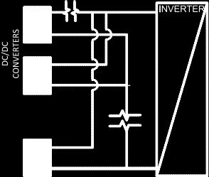
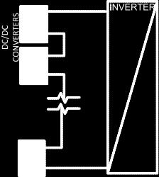
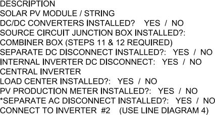
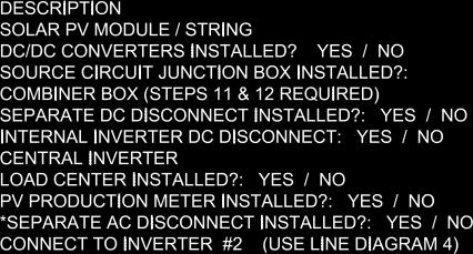
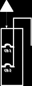
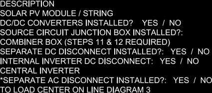
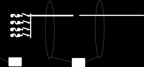
2 5) DC Module Layout Identify each source circuit (string) for inverter 1 shown on the roof plan with a Tag (e.g. A,B,C, ) Number of modules per source circuit for inverter 1 Identify, by tag, which source circuits on the roof are to be paralleled (if none, put N/A) Combiner 1: Combiner 2: Total number of source circuits for inverter 1: 6) Are DC/DC Converters used? Yes No If No, skip to Step 7. If Yes enter info below. DC/DC Converter Model #: DC/DC Converter Max DC Input Voltage: Volts Max DC Output Current: Amps Max Max DC Output Current: Volts # of DC/DC Converters in an Input Circuit: DC/DC Converter Max DC Input Power: Watts 7) Maximum System DC Voltage Use A1 or A2 for systems without DC/DC converters, and B1 or B2 with DC/DC Converters. A1. Module V OC (STEP 2) = x # in series (STEP 5) x 1.12 (If -1 T L -5 C, STEP 1) = V A2. Module V OC (STEP 2) = x # in series (STEP 5) x 1.14 (If -6 T L -10 C, STEP 1) = V Table 1. Maximum Number of PV Modules in Series Based on Module Rated V OC for 600 Vdc Rated Equipment (CEC 690.7) Max. Rated Module V OC (*1.12) Max. Rated Module V OC (*1.14) Max # of Modules for 600 Vdc Use for DC/DC converters. The value calculated below must be less than DC/DC converter max DC input voltage (STEP 6). B1. Module V OC (STEP 2) = x # of modules per converter (STEP 6) x 1.12 (If -1 T L -5 C, STEP 1) = V B2. Module V OC (STEP 2) = x # of modules per converter (STEP 6) x 1.14 (If -6 T L -10 C, STEP 1) = V Table 2. Largest Module V OC for Single-Module DC/DC Converter Configurations (with 80 V AFCI Cap) (CEC and ) Max. Rated Module V OC (*1.12) Max. Rated Module V OC (*1.14) DC/DC Converter Max DC Input (Step #6) ) Maximum System DC Voltage from DC/DC Converters to Inverter Only required if Yes in Step 6 Maximum System DC Voltage = Volts 9) Maximum Source Circuit Current Is Module I SC below 9.6 Amps (Step 3)? Yes No (If No, use Comprehensive Standard Plan) 27
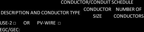
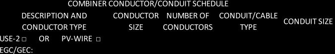
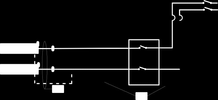
3 10) Sizing Source Circuit Conductors Source Circuit Conductor Size = Min. #10 AWG copper conductor, 90 C wet (USE-2, PV Wire, XHHW-2, THWN-2, RHW-2) For up to 8 conductors in roof-mounted conduit exposed to sunlight at least ½ from the roof covering (CEC 310) Note: For over 8 conductors in the conduit or mounting height of lower than ½ from the roof, use Comprehensive Plan. 11) Are PV source circuits combined prior to the inverter? Yes No If No, use Single Line Diagram 1 and proceed to Step 13. If Yes, use Single Line Diagram 2 with Single Line Diagram 4 and proceed to Step 12. Is source circuit OCPD required? Yes No Source circuit OCPD size (if needed): 15 Amps 12) Sizing PV Output Circuit Conductors If a combiner box will NOT be used (Step 11), Output Circuit Conductor Size = Min. #6 AWG copper conductor 13) Inverter DC Disconnect Does the inverter have an integrated DC disconnect? Yes No If Yes, proceed to step 14. If No, the external DC disconnect to be installed is rated for Amps (DC) and Volts (DC) 14) Inverter Information Manufacturer: Model: Max. Continuous AC Output Current Rating: Amps Integrated DC Arc-Fault Circuit Protection? Yes No (If No is selected, Comprehensive Standard Plan) Grounded or Ungrounded System? Grounded Ungrounded AC Information: 15) Sizing Inverter Output Circuit Conductors and OCPD Inverter Output OCPD rating = Amps (Table 3) Inverter Output Circuit Conductor Size = AWG (Table 3) Table 3. Minimum Inverter Output OCPD and Circuit Conductor Size Inverter Continuous Output Current Rating (Amps) (Step 14) Minimum OCPD Size (Amps) Minimum Conductor Size (AWG, 75 C, Copper)
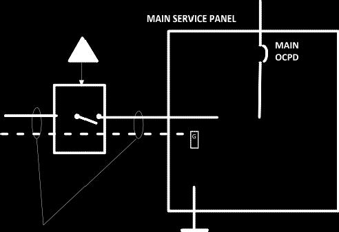
4 16) Point of Connection to Utility Only load side connections are permitted with this plan. Otherwise, use Comprehensive Standard Plan. Is the PV OCPD positioned at the opposite end from input feeder location or main OCPD location? Yes No If Yes, circle the Max Combined PV System OCPD(s) at 120% value as determined from Step 15 (or Step S20), bus bar Rating, and Main OCPD as shown in Table 4. If No, circle the Max Combined PV System OCPD(s) at 100% value as determined from Step 15 (or Step S20), bus bar Rating, and Main OCPD as shown in Table 4. Per (D)(2): [Inverter output OCPD size [Step #15 or S20] + Main OCPD Size] [bus size x (100% or 120%)] Table 4. Maximum Combined Supply OCPDs Based on Bus Bar Rating (Amps) per CEC (D)(2) Max Combined PV System OCPD(s) at 120% of Bus Bar Rating Max Combined PV System OCPD(s) at 100% Bus Bar Rating Bus Bar Rating Main OCPD *This value has been lowered to 60 A from the calculated value to reflect 10 kw AC size maximum * 60* 40 60* 60* Reduction of the main breaker is not permitted with this plan. Otherwise, use Comprehensive Standard Plan. 17 & 18 & 19) Labels and Grounding and Bonding This content is covered by the labels on the next page and the Single Line Diagram(s). For background information, refer to the Comprehensive Standard Plan. 29
5 Solar PV Standard Plan Simplified Central/String Inverter Systems for One- and Two-Family Dwellings Markings CEC Articles 690 and 705 and CRC Section R331 require the following labels or markings be installed at these components of the photovoltaic system: WARNING INVERTER OUTPUT CONNECTION; DO NOT RELOCATE THIS M WARNING DUAL POWER SOURCES SECOND SOURCE IS PHOTOVOLTAIC SYSTEM RATED AC OUTPUT CURRENT- _AMPS AC OVERCURRENT DEVICE NORMAL OPERATING VOLTAGE VOLTS CEC (D)(7) [Not required if panelboard is rated not less than sum of ampere ratings of all overcurrent devices supplying it] WARNING ELECTRIC SHOCK HAZARD. THE DC CONDUCTORS OF THIS PHOTOVOLTAIC SYSTEM ARE UNGROUNDED AND MAY BE ENERGIZED CEC (F) [Only required for ungrounded systems] WARNING: PHOTOVOLTAIC POWER SOURCE CRC R331.2 and CFC [Marked on junction/combiner boxes and conduit every 10 ] J/Box A C INVERTER D C CEC & CEC (D)(4) PV SYSTEM AC DISCONNECT RATED AC OUTPUT CURRENT - AMPS AC NORMAL OPERATING VOLTAGE VOLTS CEC WARNING ELECTRIC SHOCK HAZARD IF A GROUND FAULT IS INDICATED, NORMALLY GROUNDED CONDUCTORS MAY BE UNGROUNDED AND ENERGIZED CEC 690.5(C) [Normally already present on listed inverters] WARNING ELECTRIC SHOCK HAZARD DO NOT TOUCH TERMINALS TERMINALS ON BOTH LINE AND LOAD SIDES MAY BE ENERGIZED IN THE OPEN POSITION CEC Code Abbreviations: California Electrical Code (CEC) California Residential Code (CRC) California Fire Code (CFC) PV SYSTEM DC DISCONNECT RATED MAX POWER-POINT CURRENT- RATED MAX POWER-POINT VOLTAGE- SHORT CIRCUIT CURRENT- MAXIMUM SYSTEM VOLTAGE- CEC ADC VDC ADC VDC Informational note: ANSI Z535.4 provides guidelines for the design of safety signs and labels for application to products. A phenolic plaque with contrasting colors between the text and background would meet the intent of the code for permanency. No type size is specified, but 20 point (3/8 ) should be considered the minimum. CEC requires a permanent plaque or directory denoting all electric power sources on or in the premises. 30


6 31 Solar PV Standard Plan Simplified Central/String Inverter Systems for One- and Two-Family Dwellings
7 32
8 Solar PV Standard Plan Simplified Central/String Inverter Systems for One- and Two-Family Dwellings DC Information: Supplemental Calculation Sheets for Inverter #2 (Only include if second inverter is used) Module Manufacturer: Model: S2) Module V oc (from module nameplate): Volts S3) Module I sc (from module nameplate): Amps S4) Module DC output power under standard test conditions (STC) = Watts (STC) S5) DC Module Layout Identify each source circuit (string) for inverter 1 shown on the roof plan with a Tag (e.g. A,B,C, ) Number of modules per source circuit for inverter 1 Identify, by tag, which source circuits on the roof are to be paralleled (if none, put N/A) Combiner 1: Combiner 2: Total number of source circuits for inverter 1: S6) Are DC/DC Converters used? Yes No If No, skip to Step S7. If Yes, enter info below. DC/DC Converter Model #: DC/DC Converter Max DC Input Voltage: Volts Max DC Output Current: Amps Max Max DC Output Current: Volts # of DC/DC Converters in an Input Circuit: DC/DC Converter Max DC Input Power: Watts
9 S7) Maximum System DC Voltage Use A1 or A2 for systems without DC/DC converters, and B1 or B2 with DC/DC Converters. A1. Module V OC (STEP S2) = x # in series (STEP S5) x 1.12 (If -1 T L -5 C, STEP S1) = V A2. Module V OC (STEP S2) = x # in series (STEP S5) x 1.14 (If -6 T L -10 C, STEP S1) = V Table 1. Maximum Number of PV Modules in Series Based on Module Rated V OC for 600 Vdc Rated Equipment (CEC 690.7) Max. Rated Module V OC (*1.12) Max. Rated Module V OC (*1.14) Max # of Modules for 600 Vdc Use for DC/DC converters. The value calculated below must be less than DC/DC converter max DC input voltage (STEP S6). B1. Module V OC (STEP S2) = x # of modules per converter (STEP S6) x 1.12 (If -1 T L -5 C, STEP S1) = V B2. Module V OC (STEP S2) = x # of modules per converter (STEP S6) x 1.14 (If -6 T L -10 C, STEP S1) = V Table 2. Largest Module V OC for Single-Module DC/DC Converter Configurations (with 80 V AFCI Cap) (CEC and ) Max. Rated Module V OC (*1.12) Max. Rated Module V OC (*1.14) DC/DC Converter Max DC Input (Step 6) S8) Maximum System DC Voltage from DC/DC Converters to Inverter Only required if Yes in Step S6 Maximum System DC Voltage = Volts S9) Maximum Source Circuit Current Is Module I SC below 9.6 Amps (Step S3)? Yes No (If No, use Comprehensive Standard Plan) S10) Sizing Source Circuit Conductors Source Circuit Conductor Size = Min. #10 AWG copper conductor, 90 C wet (USE-2, PV Wire, XHHW-2, THWN-2, RHW-2) For up to 8 conductors in roof-mounted conduit exposed to sunlight at least ½ from the roof covering (CEC 310) Note: For over 8 conductors in the conduit or mounting height of lower than ½ from the roof, use Comprehensive Plan. S11) Are PV source circuits combined prior to the inverter? Yes No If No, use Single Line Diagram 1 and proceed to Step S13. If Yes, use Single Line Diagram 2 with Single Line Diagram 4 and proceed to Step S12. Is source circuit OCPD required? Yes No Source circuit OCPD size (if needed): 15 Amps S12) Sizing PV Output Circuit Conductors If a combiner box will NOT be used (Step S11), Output Circuit Conductor Size = Min. #6 AWG copper conductor S13) Inverter DC Disconnect Does the inverter have an integrated DC disconnect? Yes No If Yes, proceed to Step S14. If No, the external DC disconnect to be installed is rated for Amps (DC) and Volts (DC) 4
10 S14) Inverter Information Manufacturer: Model: Max. Continuous AC Output Current Rating: Amps Integrated DC Arc-Fault Circuit Protection? Yes No (If No is selected, Comprehensive Standard Plan) Grounded or Ungrounded System? Grounded Ungrounded AC Information: S15) Sizing Inverter Output Circuit Conductors and OCPD Inverter Output OCPD rating = Amps (Table 3) Inverter Output Circuit Conductor Size = AWG (Table 3) Table 3. Minimum Inverter Output OCPD and Circuit Conductor Size Inverter Continuous Output Current Rating (Amps) (Step 14) Minimum OCPD Size (Amps) Minimum Conductor Size (AWG, 75 C, Copper) Load Center Calculations (Omit if a load center will not be installed for PV OCPDs) S20) Load Center Output: Calculate the sum of the maximum AC outputs from each inverter. Inverter #1 Max Continuous AC Output Current Rating [STEP S14] 1.25 = Amps Inverter #2 Max Continuous AC Output Current Rating [STEP S14] 1.25 = Amps Total inverter currents connected to load center (sum of above) = Amps Conductor Size: AWG Overcurrent Protection Device: Amps Load center bus bar rating: Amps The sum of the ampere ratings of overcurrent devices in circuits supplying power to a bus bar or conductor shall not exceed 120 percent of the rating of the bus bar or conductor.

11 36

12 Solar PV Standard Plan Simplified Central/String Inverter Systems for One- and Two-Family Dwellings 37
13 38 SOLAR PV STANDARD PLAN Roof Layout Diagram for One- and Two-Family Dwellings Items required: roof layout of all panels, modules, clear access pathways and approximate locations of electrical disconnecting means and roof access points.
Solar PV Standard Plan Simplified Central/String Inverter Systems for One- and Two-Family Dwellings
 Your City logo here Solar PV Standard Plan Simplified Central/String Inverter Systems for One- and Two-Family Dwellings SCOPE: Use this plan ONLY for utility-interactive central/string inverter systems
SOLAR PV STANDARD PLAN - COMPREHENSIVE Central/String Inverter Systems for One and Two Family Dwellings
 SCOPE: Use this plan ONLY for utility-interactive central/string inverter systems not exceeding a total combined system ac inverter output rating of 10kW on the roof of a one- or two-family dwelling or
Solar PV Standard Plan Simplified Microinverter and ACM Systems for One- and Two-Family Dwellings
 TOOLKIT DOCUMENT #4 Your City logo here Solar Standard Plan Simplified Microinverter and M Systems for One- and Two-Family Dwellings SCOPE: Use this plan ONLY for systems using utility-interactive Microinverters
Solar PV Standard Plan Simplified Microinverter and ACM Systems for Oneand Two-Family Dwellings
 County of Santa Barbara Your City logo here Solar Standard Plan Simplified Microinverter and M Systems for Oneand Two-Family Dwellings SCOPE: Use this plan ONLY for systems using utility-interactive Microinverters
Solar PV Standard Plan Simplified Microinverter and ACM Systems for One- and Two-Family Dwellings
 TOOLKIT DOCUMENT #4 Solar Standard Plan Simplified Microinverter and M Systems for One- and Two-Family Dwellings SCOPE: Use this plan ONLY for systems using utility-interactive Microinverters or Modules
SOLAR PV standard Plan-Simplified Central/String Inverter Systems for One and Two Family Dwellings
 SOLAR PV standard Plan-Simplified entral/string Inverter Systems for One and Two Family Dwellings 21815 Pioneer Boulevard Hawaiian Gardens, a 90716 (562) 420 2641 E-002-a EFFETIVE : 9-31-2015 SOPE: Use
Roof Top Solar Permit Document 1 Submittal Requirements Bulletin. Solar Photovoltaic Installations 10 kw or Less in One- and Two-Family Dwellings
 Roof Top Solar Permit Document 1 Submittal Requirements Bulletin Small Town with a Big Backyard! Solar Photovoltaic Installations 10 kw or Less in One and TwoFamily Dwellings This information bulletin
Applicant and Site Information Job Address: Permit #:
 TOOLKIT DOCUENT #4 Planning and Building Services Solar Standard Plan Simplified icroinverter and Systems (One- and Two-Family Dwellings) SCOPE: Use this plan ONLY for systems using utility-interactive
Job Address: Permit #: Contractor/Engineer Name: License # and Class: Signature: Date: Phone Number:
 ity of Long Beach Department of Development Services 333 West Ocean Blvd., 4 th Floor Long Beach, A 90802 Phone: (562) 570-5237 Fax: (562) 570-6753 Website: www.lbds.info Solar PV Standard Plan - Simplified
Solar PV Standard Plan Simplified Central/String Inverter Systems for One- and Two-Family Dwellings
 Solar PV Standard Plan Simplified entral/string Inverter Systems for One and TwoFamily Dwellings SOPE: Use this plan ONLY for utilityinteractive central/string inverter systems not exceeding a system A
STREAMLINED SOLAR CHECKLIST Owner Name:
 STREAMLINED SOLAR CHECKLIST Owner Name: Address: DEPARTMENT OF PUBLIC WORKS AND PLANNING ALAN WEAVER, DIRECTOR This checklist must be completed by the contractor or an authorized agent of the contractor
Solar PV Standard Plan Central/String Inverter Systems for One- and Two-Family Dwellings
 Planning and evelopment Building & Safety ivision Solar PV Standard Plan entral/string Inverter Systems for One and TwoFamily wellings SOPE: Use this plan ONLY for utilityinteractive central/string inverter
Solar Standard Plan Simplified Systems for - and Two-Family Dwellings
 Solar Standard Plan Simplified Systems for and TwoFamily wellings SCOPE: Use this plan ONLY for electrical review of utility central/string inverter systems not exceeding a system AC inverter output rating
Solar PV Standard Plan Simplified Central/String Inverter Systems for 10 KW or less One- and Two-Family Dwellings
 Town of Woodside, Building ivision 29 Woodside Rd. Woodside, a. 902 (0) 179 Fax: (0) 1219 www.woodsidetown.org Solar PV Standard Plan Simplified entral/string Inverter Systems for 10 KW or less One and
CITY OF LANCASTER SPV TOOLKIT DOCUMENT #1
 CITY OF LANCASTER SPV TOOLKIT DOCUMENT #1 Submittal Requirements Bulletin Solar Photovoltaic Installations 10 kw or Less in One- and Two-Family Dwellings This information bulletin is published to guide
Solar PV Standard Plan Simplified Microinverter and ACM Systems for One- and Two-Family Dwellings
 TOOLKIT DOCUMENT #4 Your City logo here Solar Standard Plan Simplified Microinverter and M Systems for One- and Two-Family Dwellings SCOPE: Use this plan ONLY for systems using utility-interactive Microinverters
Submittal Requirements Bulletin Solar Photovoltaic Installations 10 kw or Less in One- and Two-Family Dwellings
 TOOKIT DOCUMENT #1 Submittal Requirements Bulletin Solar Photovoltaic Installations 10 kw or Less in One- and Two-Family Dwellings This information bulletin is published to guide applicants through a streamlined
2. Fire Department Inspections are required and available by appointment on Tuesdays and Wednesdays. See item number four for fees.
 Instructions 1. Fire Department Over the counter Plan checks are optional for solar systems complying with 2015 California Solar permitting guidebook. Although they are optional, they are highly recommended
Solar Rooftop Photovoltaic Installations 10 kw or Less in One- and Two-Family Dwellings
 Solar Rooftop Photovoltaic Installations 10 kw or Less in One- and Two-Family Dwellings This information bulletin is published to guide applicants through a streamlined permitting process for rooftop solar
Job Address: Permit #:
 Building and Safety Division Policy and Procedure No. A09301 Effective Date January 1, 2017 Expedited Permitting Process Residential RoofTop Mounted Solar Installations Form Solar PV Standard Plan Simplified
CITY OF SONOMA - TOOLKIT DOCUMENT #1
 CITY OF SONOMA - TOOLKIT DOCUMENT #1 Submittal Requirements for Solar Photovoltaic Installations 10 kw or Less in One- and Two-Family (Duplex) Dwellings This information bulletin is published to guide
Use this plan ONLY for utility-interactive central/string inverter systems. This plan is not intended for bipolar systems,
 Solar PV Standard Plan Simplified entral/string Inverter Systems for One and TwoFamily Dwellings (0 KW or Less) Use this plan ONLY for utilityinteractive central/string inverter systems. This plan is not
The following permits are required to install a solar PV system with a maximum power output of 10 kw or less:
 Effective Date January 1, 2017 Form 1 Submittal Requirements Bulletin This information bulletin is published to guide applicants through a streamlined permitting process for solar photovoltaic (PV) projects
City of Daly City Department of Economic and Community Development Building Division th Street, Daly City. CA
 GENERAL REQUIREMENTS City of Daly City Department of Economic and Community Development Building Division 333 90 th Street, Daly City. CA. 94015 A. System size is 10 kw AC CEC rating or less Y N B. The
Solar PV Standard Electrical Plan
 *** Provide this document to the inspector along with ALL system installation instructions *** Project Address: Permit Number: SCOPE: Standard plan for installation of solar PV systems utilizing 2 wire
SECTION 1: Field Inspection Guide for Rooftop Photovoltaic (PV) Systems
 Systems") COUNTY OF SANTA CRUZ PLANNING DEPARTMENT 701 OCEAN STREET, 4 th FLOOR, SANTA CRUZ, CA 95060 (831) 454-2580 FAX: (831) 454-2131 TDD: (831) 454-2123 KATHLEEN MOLLOY PREVISICH, PLANNING DIRECTOR Photovoltaic
COUNTY OF SANTA CRUZ PLANNING DEPARTMENT 701 OCEAN STREET, 4 th FLOOR, SANTA CRUZ, CA 95060 (831) 454-2580 FAX: (831) 454-2131 TDD: (831) 454-2123 KATHLEEN MOLLOY PREVISICH, PLANNING DIRECTOR Photovoltaic
Solar PV Standard Electric Plan
 *** Provide this document to the inspector along with ALL system installation instructions *** SCOPE: Standard plan for the installation of microinverter solar PV systems, not exceeding a total AC output
PHOTOVOLTAIC SYSTEMS
 PV WORKSHEET STANDARD STRING ARRAY Solar photovoltaic (PV) systems have widely gained acceptance as an alternative energy source. Installations range from small arrays supplying bus stop luminaires to
2016 Photovoltaic Solar System Plan Review List
 Building Division 555 Santa Clara Street Vallejo CA 94590 707.648.4374 2016 Photovoltaic Solar System Plan Review List GENERAL PROJECT INFORMATION PLAN CHECK NO DATE JOB ADDRESS CITY ZIP REVIEWED BY PHONE
SUPPLEMENTAL CORRECTION SHEET FOR SOLAR PHOTOVOLTAIC SYSTEMS - ELECTRICAL
 SUPPLEMENTAL CORRECTION SHEET FOR SOLAR PHOTOVOLTAIC SYSTEMS - ELECTRICAL This is intended to provide uniform application of the codes by the plan check staff and to help the public apply the codes correctly.
Solar Eligibility Checklist for Expedited Photovoltaic Permitting for One- and Two-Family Dwellings
 Solar Eligibility Checklist for Expedited Photovoltaic Permitting for One and TwoFamily Dwellings GEERAL REQUIREMETS A. System size is 10 kw AC CEC rating or less B. System is located in an area with a
Solar Power Installation Application
 Solar Power Installation Application This Form must be filled out and submitted to Logan City Light and Power Department and given authorization to proceed PRIOR to installing a solar system. Also, please
This is intended to provide uniform application of the codes by the plan check staff and to help the public apply the codes correctly.
 SUPPLEMENTAL CORRECTION SHEET FOR SOLAR PHOTOVOLTAIC SYSTEMS (ELEC) This is intended to provide uniform application of the codes by the plan check staff and to help the public apply the codes correctly.
INSPECTION REQUIREMENTS: PHOTOVOLTAIC (PV) RESIDENTIAL
 RESIDENTIAL") Photovoltaic (PV) Residential Page 1 of 10 Revision Date: 07/18/2018 INSPECTION REQUIREMENTS: PHOTOVOLTAIC (PV) RESIDENTIAL INSPECTION CODE: 703 SCOPE: RESIDENTIAL APPLICABLE CODES: 2016 CBC, CRC, CPC,
Photovoltaic (PV) Residential Page 1 of 10 Revision Date: 07/18/2018 INSPECTION REQUIREMENTS: PHOTOVOLTAIC (PV) RESIDENTIAL INSPECTION CODE: 703 SCOPE: RESIDENTIAL APPLICABLE CODES: 2016 CBC, CRC, CPC,
CHAPTER 10 ELECTRICAL. Notes:
 CHAPTER 10 ELECTRICAL 1001.0 General Requirements. Electrical wiring and equipment shall comply with the requirements of NFPA 70, National Electrical Code (NEC), or local ordinances. 1002.0 Solar Photovoltaic
Photovoltaic Solar Plan Review
 PAIGE B. VAUGHAN, CBO Director of Building and Safety Phone (310) 605-5509 Fax Line (310) 605-5598 E-mail:lbutler@comptoncity.org Building & Safety Department Photovoltaic Solar Plan Review Plan Check
EXPANSION JOINT DETAILS DURA-BLOK CONDUIT SUPPORT CONDUIT ATTACHMENT DETAIL SCALE: NOT TO SCALE GROUNDING WIRE DETAIL SCALE: NOT TO SCALE
 PV SOLAR PROJECT 2 EXPANSION JOINT DETAILS 3 DURA-BLOK CONDUIT SUPPORT PLAN VIEW ISOMETRIC VIEW CONDUIT ATTACHMENT DETAIL SCALE: NOT TO SCALE FOLLOW PANEL CLAW INSTALLATION DRAWINGS FOR PROPER INSTALLATION
Residential Photovoltaic (PV) Packet
 Packet") Development Services Department Building Division 311 Vernon Street Roseville, California 95678-2649 (916) 774-5332 Fax (916) 774-5394 Residential Photovoltaic (PV) Packet The Roseville Municipal Code
Development Services Department Building Division 311 Vernon Street Roseville, California 95678-2649 (916) 774-5332 Fax (916) 774-5394 Residential Photovoltaic (PV) Packet The Roseville Municipal Code
SOLAR PV INSTALLATIONS
 Winnipeg Information Bulletin 2016-003-B/E/S/Z SOLAR PV INSTALLATIONS An Information Bulletin is currently being created for City of Winnipeg guidelines for Solar PV Installations and will be published
2011/2008/2005 NATIONAL ELECTRICAL CODE SOLAR PV CODE COMPLIANCE REFERENCE
 2011/2008/2005 NATIONAL ELECTRICAL CODE SOLAR PV CODE COMPLIANCE REFERENCE PAGE 1 OF 5 This Reference provides a very comprehensive list of aspects of a solar PV installation that could be reviewed, clarifying
Inspector Training Workshops Module One Photovoltaic Labeling based on 2008 NEC
 Inspector Training Workshops Module One Photovoltaic Labeling based on 2008 NEC NJCE Market Manager HW Construction Department Wayne, NJ Robert A. Menist Contents Site inspections with attention on Labeling
PHOTOVOLTAIC ELECTRICAL POWER SYSTEMS INSPECTOR/INSTALLER CHECKLIST
 PHOTOVOLTAIC ELECTRICAL POWER SYSTEMS INSPECTOR/INSTALLER CHECKLIST The following checklist is an outline of the general requirements found in the 2005 National Electrical Code (NEC) Article 690 for Photovoltaic
SOLAR PHOTOVOLTAIC SYSTEMS INSPECTOR CHECKLIST
 SOLAR PHOTOVOLTAIC SYSTEMS INSPECTOR CHECKLIST The following checklist is an outline of the general requirements found in the 1999 National Electrical Code (NEC) Article 690 for Photovoltaic (PV) Power
City of Manhattan Beach Community Development
 City of Manhattan Beach Community Development Phone: (310) 802-5500 FAX: (310) 802-5501 TDD: (310) 546-3501 Photovoltaic Solar Panel Plan Check Guidelines Updated: 12-20-16 ORDINANCE NO. 15-0022 MBMC 9.06
ENGINEERING SPECIFICATION
 December 206 ENGINEERING SPECIFICATION No. of 6 DATE: 2-9-6 CATEGORY SUBJECT TABLE OF CONTENTS. Overview... 2 2. General Requirements for Service... 3 3. Definitions... 3 4. Abbreviations... 5 5. References
Technical Summary of Battery Energy Storage Systems
 Technical Summary of Battery Energy Storage Systems Based on the 2017 Massachusetts Electrical Code This document summarizes the new Article 706 in the Massachusetts Electrical Code (MEC). Article 706
RESIDENTIAL PHOTOVOLTAIC (PV) PACKET
 PACKET") Public Works Building Inspection 311 Vernon Street Roseville, California 95678-2649 916.774.5332 fax 916.774.5394 RESIDENTIAL PHOTOVOLTAIC (PV) PACKET Contents of packet: Photovoltaic Checklist (2 pages
Public Works Building Inspection 311 Vernon Street Roseville, California 95678-2649 916.774.5332 fax 916.774.5394 RESIDENTIAL PHOTOVOLTAIC (PV) PACKET Contents of packet: Photovoltaic Checklist (2 pages
City of Manhattan Beach Community Development
 City of Manhattan Beach Community Development Phone: (310) 802-5500 FAX: (310) 802-5501 TDD: (310) 546-3501 Photovoltaic Solar Panel Plan Check Guidelines Updated: 10-01-15 ORDINANCE NO. 15-0022 MBMC 9.06
Microinverters and AC PV modules are becoming. Microinverters and AC PV Modules. Different Beasts. Perspectives on PV.
 Perspectives on PV Microinverters and AC PV Modules Are Different Beasts by John Wiles Microinverters and AC PV modules are becoming very common in residential and small commercial PV systems. See photos
Non-Residential Solar Energy Photovoltaic (PV) Packet
 Packet") Development Services Department Building Inspection Division 311 Vernon Street Roseville, California 95678-2649 (916) 774-5332 Fax (916) 774-5394 Non-Residential Solar Energy Photovoltaic (PV) Packet Permit
Development Services Department Building Inspection Division 311 Vernon Street Roseville, California 95678-2649 (916) 774-5332 Fax (916) 774-5394 Non-Residential Solar Energy Photovoltaic (PV) Packet Permit
ELIGIBILITY CHECKLIST FOR EXPEDITED SOLAR POOL HEATING PERMITTING
 Building and Safety Division Policy and Procedure No. A093015 Effective Date January 1, 2017 ELIGIBILITY CHECKLIST FOR EXPEDITED SOLAR POOL HEATING PERMITTING GENERAL REQUIREMENTS A. System size is 30
Electrical Design/Build Guide
 2017 Electrical Design/Build Guide Based on the 2017 National Electrical Code Copyright Durand & Associates 1986-2016 60 C Copper Ampacity 4 - Wire Fill - (Non-Current Carrying Neutral) 4 or 5 - Parallel
Mike Holt s Illustrated Guide to SOLAR PV SYSTEMS
 Mike Holt s Illustrated Guide to Directory, Identification, Label, Marking, Plaque, and Sign Requirements for SOLAR PV SYSTEMS Extracted From Mike Holt s Illustrated Guide to Understanding NEC Requirements
Electric Vehicle Charging Station Article California Electrical code (CEC) General Requirements:
 General Requirements:") Checklist for Multi-Family Residential Electric Vehicle Charging Station Article 625 2016 California Electrical code (CEC) General Requirements: Level 1 Charger: 110V dedicated 20 amp circuit No electrical
Checklist for Multi-Family Residential Electric Vehicle Charging Station Article 625 2016 California Electrical code (CEC) General Requirements: Level 1 Charger: 110V dedicated 20 amp circuit No electrical
XXX RESIDENCE : XXX kw DC GROUND MOUNTED PHOTOVOLTAIC SYSTEM
 EQUIPMENT SUMMARY 36 NO'S - LG 335N1C-A5 335W MODULE 01 NO'S - OUTBACK RADIAN GS8048A INVERTER XXX RESIDENCE : XXX 12.06 kw DC GROUND MOUNTED PHOTOVOLTAIC SYSTEM SHEET INDEX T-01 COVER SHEET G-01 GENERAL
Load Side PV Connections
 Perspectives on PV Load Side PV Connections 705.12(D) in the 2014 NEC by John Wiles Through the exceptional efforts of the members of NFPA NEC Code-Making Panel 4 working with the proposals and comments
Solar Photovoltaic Power. Overarching Objectives. How many questions? 9/16/2012. From plan review to Final Inspection
 Solar Photovoltaic Power From plan review to Final Inspection Overarching Objectives A understandable and predictable process for both the Installer and the Inspector. The installation of safe, efficient,
COVER VICINITY MAP SCOPE OF WORK ELECTRICAL NOTES GOVERNING CODES SHEET INDEX
 SCOPE OF WORK TO INSTALL A SOLAR PHOTOVOLTAIC (PV) SYSTEM THE POWER ENERATED BY THE PV SYSTEM WILL BE INTERCONNECTED WITH THE UTILITY RID THROUH THE EXISTIN ELECTRICAL SERVICE EQUIPMENT. THE PV SYSTEM
First Responder System Identification Quiz. Presented by the NY-SUN PV Trainers Network
 First Responder System Identification Quiz Presented by the NY-SUN PV Trainers Network SYSTEM 1 Questions: 1) Is there a solar electric system at the site? 2) What is your next step? SYSTEM 1 3) Given
Green Building Technology
 Green Building Technology Renewable Energy Sources and Design/Specification Guidelines Presented by: Kurt Uhlir & Brian Kustwin Why Renewables? Reduction of SO 2 and NOX along with greenhouse gases such
RESIDENTIAL PHOTOVOLTAIC (PV) PACKET
 PACKET") Development Services Department Building Inspection Division 311 Vernon Street Roseville, California 95678-2649 (916) 774-5332 Fax (916) 774-5394 RESIDENTIAL PHOTOVOLTAIC (PV) PACKET ALL PV Project Applicants:
Development Services Department Building Inspection Division 311 Vernon Street Roseville, California 95678-2649 (916) 774-5332 Fax (916) 774-5394 RESIDENTIAL PHOTOVOLTAIC (PV) PACKET ALL PV Project Applicants:
Code Calculations. for an Off-Grid PV System
 Code Calculations for an Off-Grid PV System John Wiles Sponsored by the Photovoltaic Systems Assistance Center, Sandia National Laboratories Judy LaPointe s home is on its way to becoming a finished, off-grid
33'-10"± ROOF #1 (2) SUNPOWER SPR E C-AC MICROINVERTER MODULES ROOF #2 (13) SUNPOWER SPR E C-AC MICROINVERTER MODULES 78'-9"± 25'-5"
 SUNPOWER SPR E C-AC MICROINVERTER MODULES ROOF #2 (13) SUNPOWER SPR E C-AC MICROINVERTER MODULES 78'-9± 25'-5") PROJECT : 15 x 327 SUNPOWER SPR E20-327-C-AC MICROINVERTER MODULES ROOF MOUNTED SOLAR PHOTOVOLTAIC MODULES SYSTEM SIZE: 4.90 kw DC STC ARRAY AREA #1: 35.08 SQ FT. ARRAY AREA #2: 228.02 SQ FT. SUMMARY 15
PROJECT : 15 x 327 SUNPOWER SPR E20-327-C-AC MICROINVERTER MODULES ROOF MOUNTED SOLAR PHOTOVOLTAIC MODULES SYSTEM SIZE: 4.90 kw DC STC ARRAY AREA #1: 35.08 SQ FT. ARRAY AREA #2: 228.02 SQ FT. SUMMARY 15
Photovoltaic Installations
 Photovoltaic Installations CanSIA December 2016 Presented by: Malcolm Brown Technical Advisor Western Region Discussion Topics Bulletin 2-11-22 Plan Review Requirements Connection Authorizations for Net
CHAPTER 10 ELECTRICAL
 1001.0 General Requirements. 1001.1 Electrical Wiring and Equipment. Electrical wiring and equipment shall comply with the requirements of NFPA 70, National Electrical Code (NEC), or local ordinances.
PV Installations 2015 Electrical Code & more. Presented by: Ted Olechna Director Codes and Standards Support
 PV Installations 2015 Electrical Code & more 1 Presented by: Ted Olechna Director Codes and Standards Support What I will Cover: Who ESA is Ontario Electrical Safety Code Solar PV Voltage limitations Conductor
March Commercial Distributed Generation with Optional Energy Storage Systems
 March 018 Commercial Distributed Generation with Optional Energy Storage Systems CATEGORY SUBJECT ENGINEERING SPECIFICATION No. 1 of 3 DATE: 03-01-18 TABLE OF CONTENTS 1. Overview.... General Requirements
90.2 Scope. The installation of electrical conductors, equipment and raceways for:
 NEC Generator Primer Rules on the installation of generators and transfer switches 1 90.2 Scope The installation of electrical conductors, equipment and raceways for: public and private premises Conductors
CPS 3Phs String Inverters NEC 2014 Compliance
 Application Note: NEC 2014 Compliance Revision: 062016 CPS 3Phs String Inverters NEC 2014 Compliance This application note describes the major changes within the NFPA 70, National Electric Code, specifically
Know the Code: PV and NEC
 Know the Code: PV and NEC September 2014 PV Installer's Course ---NEC Article 690 Highlights 1 First National Electrical Code 1881 September 2014 PV Installer's Course ---NEC Article 690 Highlights 2 The
Application Note Three Phase String Inverters NEC 2014 Compliance
 Application Note Three Phase String Inverters NEC 2014 Compliance Version 2.0 July 07, 2014 The technical information and cross references of this document are subject to a continuous improvement and the
hat inspectors need to know
 W hat inspectors need to know by John Wiles Photovoltaic (PV) power systems are being installed by the thousands throughout the United States. In states like California, New York, New Jersey and a few
Western Section 101 st Annual Meeting Hot Springs, Arkansas September 21, 2005 Charlie Trout Code Breakfast
 Western Section 101 st Annual Meeting Hot Springs, Arkansas September 21, 2005 Charlie Trout Code Breakfast 1.Question: An add on unit for a hydromassage bathtub consists of a small 1-gallon water heater
A Look at the 2017 NEC Significant Changes
 A Look at the 2017 NEC Significant Changes A Look at the 2017 NEC Significant Changes Michael J. Johnston NECA James T. Dollard Local 98 Philadelphia Electrical JATC This session is eligible for 1 Continuing
APPROACHING. The Inverter. 92 IAEI NEWS May.June approaching the inverter
 APPROACHING approaching the inverter The Inverter 92 IAEI NEWS May.June 2009 www.iaei.org by John Wiles approaching the inverter In our top-to-bottom perspective of a photovoltaic (PV) system, we are still
Spring Test 10 due 05/11/2013
 Spring Test 10 due 05/11/2013 Multiple Choice Identify the letter of the choice that best completes the statement or answers the question. 1. When installed in an agricultural building that houses livestock
Electric Vehicle Charging Station Article California Electrical code (CEC) General Requirements:
 General Requirements:") Checklist for Non-Residential Electric Vehicle Charging Station Article 625 2016 California Electrical code (CEC) General Requirements: Level 1 Charger: 110V dedicated 20 amp circuit No electrical plans
Checklist for Non-Residential Electric Vehicle Charging Station Article 625 2016 California Electrical code (CEC) General Requirements: Level 1 Charger: 110V dedicated 20 amp circuit No electrical plans
Temporarily Approved Solar Photovoltaic System Electrical Schematics
 March 20, 2019 Page 1 of 10 Temporarily Approved Solar Photovoltaic System Electrical Schematics This document is intended as a temporary interpretation of approved solar photovoltaic electrical schematics
CHAPTER V RESIDENTIAL WIRING
 CHAPTER V RESIDENTIAL WIRING 5.1. THE SERVICE ENTRANCE Buildings and other structures receive the electrical energy through the service entrance. In residential wiring, the electric company supply this
9/7/2010. Objectives. Article 90. Introduction NEC Significant Changes. Review significant revisions in the 2011 NEC
 2011 NEC Significant Changes Courtesy of NJATC Courtesy of NFPA Presented By: Michael J. Johnston Executive Director of Standards and Safety, NECA Objectives Review significant revisions in the 2011 NEC
Customer Name : Account Number: Customer Service Address (Street, City, State, ZIP Code): Customer Mailing Address: Customer Telephone Number:
: Customer Mailing Address: Customer Telephone Number:") Please print the following information. Interconnect Customer Information Customer Name : Account Number: Customer Service Address (Street, City, State, ZIP Code): Customer Mailing Address: Customer Telephone
Please print the following information. Interconnect Customer Information Customer Name : Account Number: Customer Service Address (Street, City, State, ZIP Code): Customer Mailing Address: Customer Telephone
ELECTRIC SERVICE RULES DISTRIBUTED GENERATION Issued Jan 2016
 DISTRIBUTED GENERATION CHAPTER 5 500. SCOPE This chapter includes distributed or customer-owned generation connected in parallel and operating with Alliant Energy s electric distribution system. For all
Bulletin Wiring methods for Solar Photovoltaic Systems Rules, 2-034, , and , Tables 11 and 19
 Bulletin 50-4-4 Wiring methods for Solar Photovoltaic Systems Rules, 2-034, 50-014, 50-018 and 50-020, Tables 11 and 19 Scope (1) Introduction (2) New cable types RPV & RPVU (3) Wiring methods within photovoltaic
PART A General Conductor Requirements
 PART A General Conductor Requirements 6.1 Conductor Insulation Property Table 310.13 of the NEC provides information on conductor properties such as permitted use, maximum operating temperature, and other
SAMPLE PERMIT APPLICATION PACKAGE
 2013 Lennox Industries Inc. Dallas, Texas, USA SOLAR - KIT / ACCESSORIES 507154-01 3/2013 Supersedes 506555-01 LITHO U.S.A. SAMPLE PERMIT APPLICATION PACKAGE SUNSOURCE HOME ENERGY SYSTEM SAMPLE PERMIT
RGS PV-000. Sheet List
 007 ANSI Full Bleed B (.00 X 7.00 Inches) 07-0-08 Scope of Work: Energy shall install a 6.600 kw Grid-tied Photovoltaic ("PV") System totaling () Silfab SLA 00 M Modules with () Enphase Energy M0-60-LL-S
Expedited Permitting Process for Electric Vehicle Charging Stations
 Expedited Permitting Process for Electric Vehicle Charging Stations BPC-062 Purpose: This document provides all of the needed links to forms and checklists necessary to utilize Permit Sonoma s Expedited
SINGLE PHASE WIRING SPECIFICATIONS
 SINGLE PHASE WIRING SPECIFICATIONS 1-866-MEC-ELEC (1-866-632-3532) Office Locations: Hondo Office 237 Hwy 173 N Hondo, TX 78661-0370 Fax 830.426.3335 Dilley Office 1718 W. FM 117 Dilley, TX 78017 Fax 830.965.1425
Copyright 2012 DelSolar Co. Ltd MQWRD installation manual-iec Ver. 1.4
 INSTALLATION MANUAL IEC Version www.delsolarpv.com Copyright 2012 DelSolar Co. Ltd MQWRD-01-14--installation manual-iec Ver. 1.4 Content General information 1 Safety precaution for installing solar PV
THREE PHASE WIRING SPECIFICATIONS
 THREE PHASE WIRING SPECIFICATIONS 1-866-MEC-ELEC (1-866-632-3532) Office Locations: Hondo Office 237 Hwy 173 N Hondo, TX 78661-0370 Fax 830.426.3335 Dilley Office 1718 W. FM 117 Dilley, TX 78017 Fax 830.965.1425
Pretest Module 24 Three-phase Service Entrance
 Pretest Module 24 Three-phase Service Entrance 1. What is the most widely used three-phase service entrance system? 2. What are the three most common voltage combinations for three-phase, four-wire systems?
A little about me: Course Objective/Intent. Good PV resources:
 A little about me: By: Doug Smith, MCP, CBO Cell: 8015507630 Office: 8015478133 Email: Doug@kimballengcom Web: wwwkimballengcom Happily married for over 13 years I have 3 children (1 girl and 2 boys) Building
MECKLENBURG COUNTY. Land Use and Environmental Service Agency Code Enforcement 2/8/12 ELECTRICAL CONSISTENCY MEETING. Code Consistency Questions
 MECKLENBURG COUNTY Land Use and Environmental Service Agency Code Enforcement 2/8/12 ELECTRICAL CONSISTENCY MEETING Code Consistency Questions 1. I am inspecting a building addition. They have a 480V to
2014 NEC Changes (Homestudy)
") 2014 NEC Changes (Homestudy) Idaho Electrical License This course will review the most important National Electrical Code changes from the 2014 NEC. Changes in Articles 100 - Chapter 9 will be covered.
2014 NEC Changes (Homestudy) Idaho Electrical License This course will review the most important National Electrical Code changes from the 2014 NEC. Changes in Articles 100 - Chapter 9 will be covered.
Residential microinverter system
 PV array Rooftop junction box to transition from TC-ER cable to THWN-2 Conduit run over 10 ft. long GARAGE Existing exterior service panel Residential microinverter system If an inverter is dedicated to
DIRECTORY, IDENTIFICATION, LABEL, MARKING, PLAQUE, AND SIGN REQUIREMENTS FOR SOLAR PV SYSTEMS
 Mike Holt s Illustrated Guide to DIRECTORY, IDENTIFICATION, LABEL, MARKING, PLAQUE, AND SIGN REQUIREMENTS FOR SOLAR PV SYSTEMS Based on the 2014 NEC Articles 690 and 705 Extracted from Mike Holt s Understanding
Washoe County PLAN SUBMITTAL
 Washoe County PLAN SUBMITTAL Washoe County PLAN SUBMITTAL Solar Photo Voltaic Systems Electrical Generation Systems December 2013 Washoe County Permits Plus Zone 1001 East Ninth Street PO Box 11130 Reno,
Code Compliance. Perspectives on PV. Back to the Grid, Designing PV Systems for
 Perspectives on PV A series of articles on photovoltaic (PV) power systems and the National Electrical Code by John Wiles Back to the Grid, Designing PV Systems for Code Compliance 20 IAEI NEWS January.February
2014 NEC Changes Part 1 (Homestudy)
") 2014 NEC Changes Part 1 (Homestudy) Wisconsin Electrical License This course will review the first half of the most important National Electrical Code changes from the 2014 NEC. Changes in Articles 100-404.2
2014 NEC Changes Part 1 (Homestudy) Wisconsin Electrical License This course will review the first half of the most important National Electrical Code changes from the 2014 NEC. Changes in Articles 100-404.2
INSTALLATION MANUAL.
 INSTALLATION MANUAL D6M_BxA Series : D6M_B1A / D6M_B2A / D6M_B3A / D6M_B5A D6M_AxA Series : D6M_A1A / D6M_A2A / D6M_A3A / D6M_A5A D6P_BxA Series : D6P_B1A / D6P_B2A / D6P_B3A / D6P_B5A D6P_AxA Series :