Spearhead. Excel 474 Reach Mower & Twiga Handbook 1 st Edition - March 2008
|
|
|
- Wilfrid Marsh
- 5 years ago
- Views:
Transcription
1 Spearhead Excel 474 Reach Mower & Twiga 4000 Handbook 1 st Edition - March 2008 Please ensure that this manual is handed to the operator before using the machine for the first time. The operator must fully understand the contents of this manual before using this machine. (If the machine is resold the Manual must be given to the new owner.) Important Note The information contained in this manual is correct at the time of publication. However, in the course of constant development, changes in specification are inevitable. Should you find the information given in this book different to the machine it relates to please contact the After Sales Department for advice Spearhead Machinery Green View, Salford Priors, Evesham, Worcestershire, WR11 8SW Tel: Fax: enquiries@spearheadmachinery.com 1
2 EC Declaration of Conformity, Conforming to EEC Directive 89/392/EEC, 98/37/EC & 98/38/EC We, Spearhead Machinery Ltd, Green View, Salford Priors, Evesham, Worcestershire, WR11 8SW declare under our sole responsibility that the : Product Product Code Serial No Flail Head Serial No Type Manufactured by the above company complies with the required provisions of the directive 89/392/EEC, 98/37/EC and 98/38/EC and AMD 91/368/EEC, AMD 93/44/EEC, AMD 93/68/EEC and conforms with European norm. BSEN 292; Part 1: 1991 Safety of Machinery Technical, Methodology; Part 2: 1991 Safety of Machinery - Technical Specifications and other national standards associated with its design and construction as listed in the Technical File. Signed.. (On behalf of Spearhead Machinery Ltd) Status General Manager Date... 2
3 Contents General Information Introduction 4 Specification 5 Safety Machine Safety Stickers 6 Safety Recommendation 7 Signs 9 Training 9 Installing/Removing Machine Tractor Requirements 10 Lifting Points 10 Attaching Your Machine To The Tractor 11 Running up your Machine 16 Removing from the Tractor 17 Set-up Hydraulic Controls 18 How your Controls Work 19 Flail Head Set-Up 20 Hedge Trimming 21 Operation Optional Hydraulic Rear Roller 22 Operation s 23 Moving into Transport Position 24 Transport to Work Position 25 Engaging Head Drive 26 Disengage Head Drive 26 Break Back 27 Tractor Forward Speed 28 Cutting Sequence 28 Wire Trap 29 High Voltage Cables 29 Optional Angle Float 30 Optional Head/Arm Float 31 3
4 Service & Maintenance Greasing / Lubrication 32 Hydraulic hoses 34 Oil Supply 35 Oil Recommendations 35 Filtration Maintenance 35 Flail Head 36 Cables 37 Pin & Bushes, Storage 37 Storage 37 Torque Settings 38 Regular Service Chart 38 Diagnostics Trouble shooting Excel 39 Pump and Motor failure 42 Warranty The Spearhead Warranty 43 Extended Warranty 44 4
5 Introduction The Excel is a very robust medium capacity hedge trimmer that is easy to operate and maintain, ideally suited for annual trimming of field boundaries. To ensure trouble free operation this manual should be carefully studied. The term Left and Right hand applies to the machine when coupled to the tractor and viewed from the rear, this also applies to the tractor. 5
6 Specification Weight including head & oil (kg) Tractor (hp) Minimum tractor weight (kg) Oil tank capacity A reach (m) B reach (m) C reach (m) D reach (m) E reach (m) Excel kg hp 2500 kg 200 ltr 4.58 m 5.45 m 2.80 m 4.25 m 4.38 m 6


7 Machine Safety Stickers Avoid fluid escaping under pressure. Consult technical manual for service procedures. Shut off engine and remove key before performing maintenance or repair work. Beware of overhead electrical power line. Danger flying objects keep safe distance from the machine as long as the engine is running. Stay clear of mower flails. Do not remove/ open guard. Carefully read operator s manual before handling this machine. Observe instructions and safety rules when operating. Check all nuts and bolts are tight every 8 hours 7
8 Safety Recommendations Beware of the following Potential Dangers associated with the use of this machine: Becoming trapped when hitching or unhitching Tractor overbalancing when arm is extended Electrocution due to hitting overhead power lines Getting caught on rotating power take off (PTO) Being hit or caught by any moving part, e.g. belts, pulleys, arms, cutting head Being hit by flying debris or machine parts due to machine damage Machine overbalancing when not in use Injection of high pressure oil from damaged couplings or hydraulic hoses Accidents due to collision with other machines, or debris left on road Always Ensure the operator has read this handbook and has been trained to use the machine. Ensure all cab safety guards are in place and all tractor windows closed. Before leaving the tractor cab always ensure that the flail head is firmly on the ground, no weight is on the machine s hydraulics and the rotor has stopped spinning. Check that all guards are properly fitted and there are no damaged or loose parts. Particular attention should be given to the flails to ensure they are not damaged, cracked or missing. Inspect work area for wire, steel posts, large stones and other dangerous materials and remove before starting work. Beware of the danger of overhead power cables. The operator must be aware of the maximum height and reach of the machine when working under power cables. The minimum legal height for 11,000 and 22,000-volt cables is 5.2 metres from the ground. When fully extended, the machine may well exceed this height so extreme caution should be practised. For more information contact the Health and Safety Executive or your local power company. Ensure that all warning labels are always visible and that they are not damaged, defaced or missing. Lower the head to the ground when parking up Fit locking pins to slew and height before transport and before unhitching when applicable. Wear ear defenders if operating without a quiet cab or with the cab windows open. Ensure tractor guards are fitted correctly and are undamaged Work at a safe speed, taking into account terrain, passing vehicles and obstacles 8
9 Ensure that the tractor meets the minimum weight recommendations of the machine manufacturer and that ballast is used if necessary Check that machine fittings and couplings are in good condition Follow the manufacturer s instructions for attachment and removal of machine from the tractor are warning signs to alert others to the type of machine working in the vicinity. Signs should be placed at both ends of the work site and should be in accordance with Department of Transport recommendations. Ensure flails are of the type recommended by the manufacturer, are securely fitted and are undamaged. Ensure hydraulic pipes are correctly routed to avoid damage from chafing, stretching, pinching or kinking. Disengage the machine, stop the engine and remove the key before leaving the tractor cab for any reason. Clean up any debris left at the work site. Ensure that when you remove the machine from the tractor it is secured in a safe position using the stands provided. Never Never operate the machine with other people present, as it is possible for debris, including stones, to be discharged from the front and rear of the flail head. Never operate the machine until you have read and understood the relevant Handbook and are familiar with the controls. Never use a machine that is poorly maintained or has guards that are damaged or missing Never allow an inexperienced person to operate the machine without supervision. Never use or fit a machine onto a tractor if it doesn t meet the manufacturer s specification. Never use a machine if the hydraulic system shows signs of damage. Never attempt to detect a hydraulic leak with your hand, use a piece of card. Never allow children to play on or around the machine at any time. Never attempt any maintenance or adjustment without first disengaging the PTO, lowering the head to the ground, stopping the tractor engine and applying the tractor parking brake. Never leave the cab without removing the ignition key. Never operate the tractor or any controls from any position other than from the driving seat. Never stop the engine with the PTO engaged. Never operate with flails missing. Never operate PTO above recommended speed, 540 R.P.M. Never operate with wire around the rotor. Stop immediately. Never use the head at an angle, which may throw debris towards the cab. Never attempt to use the machine for any purpose other than that it was designed for. Never transport with the PTO engaged Never enter the working area of the machine (risk of injury!) Never transport with the controls live, always turn off electrical isolator switch (red) and disconnect supply. 9

10 Signs You are advised to display clear warning signs to indicate the type of machine when working in public places. The signs should be carefully placed at either end of the work site to give advanced warning of the hazard. Contact your local Highways Authority or Department of Transport for more information. Roadwork Guidelines: On two-way roads, one set of signs should face the traffic in each direction. Work should be within 1 mile of the signs. Work only when visibility is good and at times of low risk, e.g. NOT during rush hour. Vehicles should show an amber flashing light. Vehicles should be conspicuously coloured. Debris should be removed from the road or path at regular intervals and the operator should wear high visibility clothing. Collect all warning signs promptly when the job is finished. Training It is the responsibility of the Spearhead dealer to provide instruction on the safe installation, operation and maintenance of the machine in the first instance. Further training is available from Spearhead Machinery Ltd on request, at cost. Lifting Point 10

11 Tractor Requirements Check your tractor size and minimum weight on the Specification table (page 5). Before hitching, ensure position control is selected. DO NOT attempt to hitch in draft control. Set wheel width as wide as possible. Front and offside ballast weight is to be fitted within tractor manufacturer s recommended requirements. Check chains and stabilisers must be in good working order to hold the machine firmly. Do not operate without ensuring that chains and stabilisers are tight. Spearhead particularly recommend turn buckle type stabiliser. A linkage isolation facility is necessary for all models. Set linkage lift rods to an equal length. Joystick machines require a 12v fused supply. A 30 amp DIN connector is provided, but if not, the lead should be taken directly to the vehicle battery. Avoid cigarette lighter plugs, as they are unsuitable. The supply cable has a red wire for positive (+ve) and black wire for negative (-ve) Spearhead particularly recommend Category 2 three point linkage of ball end type, we do not advise the use of claw type hitching. When using hooks the quick release latches should be checked, if worn or insecure they may cause accidental damage or personal injury if the machine becomes detached. The machine is sold to suit Cat. 2 linkages, some modification may be necessary before mounting on Category 3 linkage. Ensure tractor link arms can be isolated from accidental lifting. 11


12 Attaching Your Machine To The Tractor 3 Point Linkage It is most important the operator fully understands the procedure for attaching/unattaching the reach mower to/from the tractor. The following text must be fully understood before attempting to attach the machine. If there is any doubt please contact your supplying dealer or Spearhead Service Department. Failure to follow the correct procedure to attach/un-attach the machine could result in personal injury or machine damage. Any resulting damage to a machine is not covered by warranty. Always be sure to select a level firm surface, such as concrete before attaching to the tractor. When operating the tractor or machine s controls do so only when seated in the tractor cab. Do not allow anyone to stand on or amongst linkage for any reason. 1. Fit stabiliser yoke to the tractor s top hitch bracket. 2. Reverse tractor and attach lower link arms by inserting lower linkage pins into the outer holes. 3. Place the stabiliser tubes to the inner holes on frame insert the same lower linkage pin to secure. 12


13 Attaching Your Machine To The Tractor 3 Point Linkage 4. Swing forward stabiliser bars and attach to stabiliser yoke. Be sure the stabiliser bars are free to slide. Do not fit locking pins. 5. Fit top link between machine and the tractor 6. Caution: when positioning the top link, it is most important to select the most suitable hole position to achieve as near as possible a straight line between all 3 holes. 7. Lift the machine up on the tractor s hydraulics until both PTO stub shafts are approximately in line. PTO angle may vary between tractor makes - up to 17 above horizontal is acceptable. Ensure there is enough ground clearance below frame. 13

 = 825mm 10.")
14 Attaching Your Machine To The Tractor 3 Point Linkage 8. Check the machine is at the correct height and level, ensuring both stabiliser bars are at an equal length. Fit locking pins to both stabilisers. Once the stabilising bars are correctly fitted, lower the tractor hydraulics allowing all the weight of the machine to be carried by the stabiliser bars. 9. If fitting the PTO shaft for the first time measure and cut to the correct length. Example: A (900mm minus 75mm) = 825mm 10. Fit the PTO shaft connecting the tractor output shaft to the machine input shaft. Always stop the engine and ensure the PTO drive is disengaged before fitting the PTO. Always replace slew pin for the transport and before unhitching the hedge cutter. 14


15 Attaching Your Machine To The Tractor 3 Point Linkage 11. Spearhead strongly recommend mounting the control unit to the seat in place of the armrest to the head side of the tractor. Modification and additional bracket may need to be fabricated Consult your local dealer for advice. An electric 12-volt supply cable will be needed from a 30-amp source for joystick model. 12. Remove locking pin from slew post before operating the machine, and slew forward Remove slew-locking pin 13. Operate the main arm to bring the frame horizontal by lowering the head weight to the ground. Adjust top link 14. Adjust top link length until the main frame is vertical. 15


16 Attaching Your Machine To The Tractor 3 Point Linkage fully tighten chains and linkage stabilisers to hold the machine rigid. There must be no sideways movement, it is very dangerous. 16. Remove parking stands and store safely. The machine cannot be unhitched without these stands. Avoid raising the tractor linkage once the stabiliser bars are locked in place. Always lower the tractor linkage and allow all the weight to be carried by the stabiliser frame. Failure to observe this warning will result in bending the stabiliser bars. 17. Use only tractors with safety glass. If windows are not laminated safety glass, polycarbonate glazing must be fitted between operator and cab meshing. Shape mesh to cover all windows that the driver will look through to view flail head in any operating position. Mesh can be retained by springs and clips supplied, but it is the operators responsibility to ensure guarding is firmly in place. 16
17 Running Up Your Machine 1. First ensure the rotor is in the off position and PTO drive is disengaged, then start the tractor. 2. Engage PTO into gear and run machine up to half revs, allowing oil to circulate for about 15 minutes before operating arms. 3. Re-check oil level, - check for oil leaks. All Spearhead machines have been fitted to a tractor and checked thoroughly. However, hose connections can become loose in transit and these should be checked again before the machine is put to work. 4. Operate the arms through the full amount of travel; check all movements are functioning correctly. 5. Place flail head near ground in a safe position and with tractor revs low, select start position for the flail motor. 6. Once the rotor is settled, slowly increase revs of PTO to 540r.p.m. and run for a further 5 minutes. Slowly reduce revs and then disengage PTO. 7. Check all hoses for kinks, pinching, chafing and leaks. 8. Re-check oil level. The rotor will take a long time to stop. Never leave the cab until PTO is disengaged, engine stopped and rotor has stopped spinning. 17


18 Removing From The Tractor The following steps MUST be followed in exactly the same order in which they appear, with removal of the top link being the last action before driving the tractor away. Do not attempt to operate machine controls through the rear cab window whilst standing on or amongst the linkage. 1. Select a level firm site such as a concreted surface. 2. Fit parking stands. Place the flail head on the ground approximately 1m out from machine main assembly, to the rear. 3. Ensure head float is discharged and turned off. 4. The arms must be slewed back into transport position and the locking pin fitted to slew post. 5. Disengage PTO. 6. Slightly raise the lower lift arms with great care to take the weight to enable the stabiliser locking pins to be removed. Be very careful not to raise the machine, as the stabiliser bars will get damaged if locked with a pin. 7. Lower all weight securely onto parking stands (Fig.1). Fig Stop engine; ensure all weight is off the tractor and machine hydraulics. 9. Remove stabiliser bars, lower link pins, and PTO shaft and control unit from the cab. 10. Remove top link. 11. Slowly drive tractor away. Subsequent Attachment to a Different Tractor Follow the steps for Attaching Your Machine To The Tractor (page 11). 18
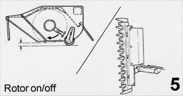
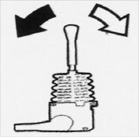
 5 Rotor on/off (red) Rotor")
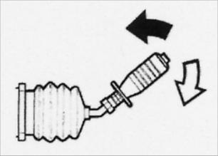
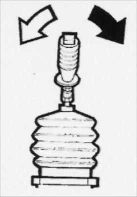
 Head float/angle float (green) Head")

19 Hydraulic Joystick Control 3 Head angle control (black) 5 Rotor on/off (red) Rotor indicator 1, 2 Main/dipper arm On/off switch (red) Head float/angle float (green) Head float 4 Manual slew (black) Hydraulic roller Cable Controls See explanatory diagram on page 19 19


20 How Your Controls Work Movements Cable controls Hydraulic/Electric controls 20


21 Flail Head Set-Up Direct Drive option minimises weight at the end of a long arm, by compact mounting and benefit of reduced maintenance. Running at a single speed of 2700 rpm. Cutting Width Standard 1.2m is suitable for hedges, and optimises power to weight ratio. We DO NOT recommend fitting a 1.5m flail head. Never attempt to operate the machine without the rear roller correctly fitted. The roller performs a key safety function should the rotor shaft pick up wire. It is essential for operator safety that it remains in place. It is also an essential structural part of the cutting head. Removing it will cause premature wear on rotor bearings and will lead to fatigue on the steel fabrications. 21


22 Hedge Trimming Recommended for Hedge Trimming - 1.2m rotor - 5 Rear roller - T flails or Boot flails - Rear flap - Front flap Note: The 1.5m head is not recommended on Excel 474 models. Roller Set-Up Roller should be set to just clear the top of the hedge. Normal Hedge Cutting Flail is cutting upwards reducing flying debris to minimum and leaving a tidy finish. Open adjustable front hood as required. Rough Cutting/Reverse Rotation When reversing rotor rotation open the front cowling or remove if necessary. This method of down cut is not good for the hedge and leaves an untidy finish. Only use this position when rough cutting in heavy growth. Do not remove cowling from the head when cutting up. 22


23 Optional Hydraulic Rear Roller (not available with cable controls) Grease daily Set-up for hedge trimming uses large stops in either position at bottom of adjustment slot keeping the roller high, for a short cut. Set-up for mowing with roller on the ground on the last pass during hedge trimming uses small stops in either position, with the option of an additional stop at the top of the adjustment slot. The hydraulic rear roller is operated by a switch on the control panel. The rear roller is either raised or lowered; there is no in-between height control, this is achieved by the size and position of the stops fitted. Hydraulic rear roller control switch location depends on machine options specified. Note To ensure the roller moves freely its important to keep the roller Side plates and head cowl clean and lubricated Attention When hedge trimmer is fitted with reverse rotor direction control the hydraulic rear roller will not function. To set rear roller when rotor is reversed, bolts must be fitted to Hold the roller in position. 23
24 Operation s Please read all the following operation warnings carefully - Never drive the tractor with arm out-stretched (except when cutting). When moving from work always first retract arms. Transport with care, metal fatigue is always caused by careless transportation and misuse. If the ground is uneven or bumpy, slow down. - Read this manual and be fully familiar with all operational maintenance and safety procedures. - Practice in open space without rotor running until familiar with controls. Take care working the head close to the tractor, as it may be possible to strike the tractor. - Remember one of the clever features of the Excel range is its ability to operate within a very narrow space, often within the tractor s width. This will mean it is quite possible for the flail head to foul the tractor. When in confined space the main arm will need to be slightly slewed backwards from normal working position. Practice all these positions and be very familiar with your machine before ever attempting work. - Never operate above the recommended PTO speed of 540r.p.m. Failure to heed this warning will result in severe damage i.e. reduced belt and pulley life (when fitted); greatly increased oil temperature; risk of rotor going out of balance, as well as reduced machine life, and may cause expensive repairs. - Failure to start and stop the rotor at a low PTO speed or to operate at the correct speed will result very quickly in severe motor and/or pump damage. - Never attempt to slew arms when fully out stretched - always retract before operating the slew. Be very careful when operating on sloping ground. - Never attempt to slew arms with the head on the ground, always raise the head before slewing. - Never attempt to operate the machine while going backwards. It will immediately damage the arms and possibly the flail head. Remember, before selecting reverse gear always lifts the flail head out of work and retract the arms towards the tractor. 24

25 Moving Into Transport Position Always transport machine with the slew locking pin and transport link fitted and the arms closed in their transport position on the bump stops. Avoid high transport speeds which will cause unnecessary strain on machine and tractor. Never travel with the reach arm away from bump stop on the main arm. Failure to adhere to this warning will cause damage to ram seals and arms. Do not attempt to move the main lift ram until transport link has been removed. Failure to adhere to this warning may cause damage to the frame, link or ram. 1. Disengage head motor drive Ensure that arm and angle float are discharged and turned off (if fitted). Retract arms to bring fail head approx 1 metre from tractor wheel and 1 metre off the ground. Slew rearwards to fully close slew ram. 2. Gently close reach arm into cradle and bump stop on main arm. 3. Carefully position main boom over the tractor cab roof. : Boom may over centre and drop onto cab roof if placed to close. 25


26 4. Mount adjustable transport link 5. Fit locking pin into slew frame. Transport To Work Position Remove locking pin from slew post, and then remove the transport link. Ensure motor valve lever is off, engage P.T.O. low revolutions. Position head 45 to the dipper arm. Lower main lift ram only, until main arm is vertical Extend dipper arm outward. Slew arm forward through 90. Position head till horizontal, just above ground. 26
27 Engaging Head Drive Select 540rpm PTO and run with low engine revs. With flail head in safe position move rotor control lever reward (5) to ON. Cold start - it is important not to run at full speed with cold oil. Run at low speed for at least 15 minutes to allow oil to warm up. Afterwards slowly increase engine revs to obtain correct PTO speed, 540rpm. Never attempt to start rotor while under load. Disengage Head Drive Slowly decrease engine revolutions to a fast idle. Move rotor control lever toward middle (5) to OFF. Never increase or decrease PTO speed rapidly, this could seriously damage pumps and motor. Reversing Head Drive Slowly decrease engine revolutions to a fast idle. Move rotor control lever (5) to OFF Wait for rotor to stop spinning and come to a stand still. Move the red knob to change the gate on the rotor control lever. Move rotor control lever forward (5) to ON Never attempt to change the rotor rotation until the rotor shaft has come to a standstill, Never attempt to use the rotor reverse facility to unblock the flail head. Serious harm to both pump and motor will result from a pressure spike. 27

28 Break-Back System Manual Standard The Excel range of reach mowers have as standard a slew ram to position the machine from transport to work or any position midway for narrow lane cutting. This ram also acts as the break back ram for machine protection should an obstacle be encountered while travelling forward. The break back will operate if the machine is overloaded i.e. a dense patch of vegetation, too high a forward speed, and when working uphill. The tractor must be halted and the flail head manoeuvred around the obstacle before the break back is reset via slew control lever no.4. Manual Recommended for Confined areas and on steep hills Auto Reset - Joystick Models Only With auto reset the flail head and arm will slew back past an obstacle, once past, the charge pressure within the hydraulic circuit causes the arm to automatically slew fully forward position. Therefore, when grass mowing too much weight on rear roller will cause arm to break back prematurely, as will too high a forward speed and a dense crop. To improve the machine s performance keep the hydraulic circuit fully charged by operating the slew lever periodically, also ensuring only a light contact when mowing with the roller on the ground. Auto reset Recommended for Normal use Never attempt to operate the machine when travelling backwards, the break back will not function and any damage caused will not be considered warranty. The break back feature does not excuse the machine operator of their need to be aware of obstacles and to avoid hazards. It is your responsibility to maintain a long reliable working life. 28


29 Tractor Forward Speed Too high a forward speed will impair the finish, leaving it looking ragged, cause over frequent use of the break back, and overheat the oil. A slower forward speed improves the standard of the finish. Cutting Sequence Cut field side and bottom of hedge first. Cutting hedge from roadside Never operate with flail rotor facing towards the tractor. This is potentially dangerous with debris being thrown towards the tractor, Unseen hazards will cause damage to the rotor and possibly the arm, as the break-back cannot function. 29


30 Wire Trap This is located under the front hood. It must not be interfered with in any way. Any wire must be removed immediately. Lower rotor to ground, move rotor control lever to off and wait until rotor stops spinning. Disengage PTO and stop engine before leaving cab. Wire is extremely dangerous and must be avoided at all times. Inspect work area before commencing, removing all loose wire and clearly marking fixed wire. High Voltage Cables Always be very aware of overhead cables. Between poles wires can be well within reach of the machine. If in any doubt of the danger, consult your local electricity company regarding a safe procedure for work. 30

31 Optional Head Angle Float Cable Control Hydraulic Controls Head Angle Float This option allows the flail head to follow contours of the ground without having to constantly control the angle of the head. The centre of balance is the best mounting point for the head if angle float is to function properly, slide head along box section mount to suit. Operating The Head Angle Float Place flail head on the ground and switch on angle float control, this opens the head ram to tank, and allows the ram to extend or retract, maintaining full contact with the ground automatically. To regain manual control switch off and operate the ram full stroke in and out to expel any air. Do not fold the machine up for transport before turning off the angle float. 31

32 Optional Head/Arm Float Head/Arm Float This is only used in verge mowing set up, it will reduce weight on the rear roller allowing head to move more easily, following small changes in ground contours in a forward motion, with the aid of a pre-charged gas accumulator. Operating The Head/Arm Float To select head float, first lower cutting head to the ground, disengage PTO and stop tractor engine. To the back of the slew frame is situated the float on/off tap. Turn tap in line for on float. Main Lift control lever should be operated to take a proportion of the flail head weight off the rear roller. This is important, as too little weight on the rear roller will leave uncut areas of grass, too much weight on the roller will cause scalping in places and increase flail wear and damage. We strongly recommend the use of auto reset - break back (if fitted). When the head is pushed further out more weight will be applied to the accumulator causing the head to drop, reset with control lever. As the ground contours alter it is necessary to reset the pressure within the main lift circuit as above, constantly raising or lowering control lever for the main lift. Do not fold the machine up for transport before turning off the head/arm float. 32
33 Service & Maintenance Before you attempt to do any repair, service, maintenance or adjustment on your machine, ensure the engine has stopped and the key is removed. P.T.O. is disengaged, handbrake secure, and the head is firmly on the ground. Greasing/Lubrication Points All the following grease points need to be greased daily 33


34 Lubrication Chart Greasing/Lubrication Washing your machine Grease all your machine and optional parts after each time you wash your machine. Gearbox Gearbox oil level / quantity 380cc. Replace after 50hrs then once a year with EP90. Note: Do not over tighten filler / drain plugs as this will damage gearbox casing. PTO Dismantle; clean the input drive shaft sliding surfaces and re-grease, failure to do this will result in serious damage to the gearbox. Grease both U.J. joints every 8 hours. Motor Drive - Direct Drive Motor drive splines are lubricated via the rotor bearings and should be greased every 8 hours with pumps of grease. Oil requirements Fill the tank to centre of sight gauge with approximately 200 litres of Texaco Rando HD46 or equivalent oil. Do not over fill. 34
35 Service & Maintenance Hydraulic Hoses Carefully check condition of all hoses during routine service, paying particular attention to chafed outer casing. Securely wrap with waterproof adhesive tape to stop the metal braid from rusting. Daily inspect all hydraulic hoses and fittings to be in good order. Any damages or leaks must be rectified immediately, this is part of the daily maintenance and it is your responsibility to help ensure a long reliable working life. Hoses with damaged metal braid should be replaced. When replacing hoses, quote number stamped on fitting at one end. The Spearhead hydraulic system works at very high pressure. Use only genuine hoses; a burst hose could be very dangerous. Always replace hoses in exactly the same way they were removed, and to avoid twisting during fitting use two spanners to slacken and tighten. Hose is weakened when installed in twisted position. Also, pressure pulses in twisted hose tend to fatigue wire and loosen fitting connections. Design so that machine motion produces bending rather than torsion. Always check the yellow protective sleeving is in good order, replacing sleeving is far cheaper than replacing expensive hoses. Hose warranty is limited to replacement of hoses due to faulty materials or manufacture. Warranty will not be considered on hoses damaged by chaffing, abrasion, cuts or pinching while in work, or to damaged threads due to over tightening. Recommended torque settings for nut BSP (size) Tightening (Nm) Torque (lbs/ft) 1/ / / / Recommended torque settings for hose unions in conjunction with bonded seals BSP (size) Tightening (Nm) Torque (lbs/ft) 1/ / / / All hose connections are of a Parker soft seal type and only need 1/2 a turn more than finger tight to become leak proof. When dismantling, the hose should be manually flexed to relieve any pressure, and the retaining nut slackened before complete disassembly. 35
36 Service & Maintenance Oil Supply Daily before starting up check oil level in tank reservoir. It is a good practice to constantly keep an eye on the tank level gauge, (this can be seen from the tractor seat) as a pipe burst could empty the tank within minutes. A pump or motor which is starved of oil will be damaged beyond repair. Replace oil if signs of contamination occur (discoloured) Contamination can be reduced by: -Thoroughly cleaning around reservoir cap before removing. -Using a clean container when replenishing the system. -Regularly servicing the filtration system. -Never allow oil level to fall below the sight gauge. Daily inspect all hydraulic connections and fittings. Any damage or leaks must be rectified immediately, this is part of the daily maintenance and it is your responsibility to help maintain a long reliable working life. When tightening fittings always use two spanners when necessary and do not over tighten. If a fitting persists in leaking it will need to be replaced. Oil Recommendations Oil Supplier Description Texaco Rando HD 46 Rando HDZ 46 Esso Univis N 46 Shell Tellus 46 Tellus T46 BP Bartran 46 Energol HLP-HM 46 Castrol Hyspin AWH-M 46 Total Equivis ZS 46 Elf Hydrelf HV 46 Hydrelf XV 46 Filtration Maintenance The machine is protected by a suction strainer and a full flow returns line filter. 1. The suction filter (inside tank) is permanently fixed in the reservoir tank. Should symptoms of pump cavitations or spongy operation occurs the tank must be drained, and the tank and suction filter thoroughly cleaned and dried before refilling with clean oil. 2. The return line filter element (top of tank) should be replaced after the first 50 hours and thereafter at 300 hour intervals. It is most important to replace the filter within these intervals because once blocked, oil will bypass the filter element un-filtrated, causing pump & motor damage 3. On hydraulic proportional controls only the mini filter (top of tank) must be replaced at 300 hour intervals. 4. If any failure or replacement of hydraulic parts have occurred then the return line filter must be replaced immediately. 36
37 Service & Maintenance Flail Head Grease all bearings daily Check there is no wrapping of string, plastic, grass or other debris on rotor shaft and rear roller bearings. Check the condition of flails and ensure all retaining bolts are tight. When flails are replaced care must be taken to maintain balance of rotor shaft, do not change to a different type. Flail retaining bolt and nut torque setting is 200Nm. Flail head is supplied centre mounted to get best travel on crowd ram. Never operate with any flails missing. This will cause severe vibration and lead to rapid bearing wear and quickly cause the head to crack. Blunt flails leave an untidy finish and absorb excessive power, when resharpening always wear protective clothing and goggles. When flails are showing severe wear, damage or cracking, they must be replaced immediately. Never attempt to weld the flails, as this will make them very brittle and extremely dangerous. Do not take risks with flails, if in doubt replace. When replacing flails always replace bolts, nuts and bushes with new. Regularly check that all rotor bearing bolts and hydraulic motor retaining bolts are tight. With a new machine or if new bolts have been fitted, particular attention needs to be applied to regular tightening of the new bolts. (1hr - 4hrs then daily). 37
38 Service & Maintenance Cables Care should be taken during installation and operation to ensure the cables are not trapped or kinked. Correctly adjusted cables will position the lever with equal amount of travel in either direction from neutral. It is recommended to pack with grease all moving parts of cable operated spool valve, especially the motor control, to ensure reliability. Pins & Bushes All main pivot points are furnished with replaceable pins and bushes. If there are any signs of wear, these must be replaced. The pins are secured with a nut and bolt through the head to prevent turning. A retaining washer and screw are clamped to the base of the pin to prevent spreading and must be kept tight (use locking compound). Storage Before storing away, thoroughly wash the machine, removing all traces of grass and dirt. Great care must be taken when washing with high pressure hoses, do not hold the water jet close to the paintwork. Use steam cleaners with caution; be sure to remove all detergents to avoid any discolouring or damage to paint. Lubricate all grease points until fresh grease shows. Slacken rotor drive belts (where fitted). It is important where possible to store undercover to protect against rain and sunlight. Always ensure a firm level surface. Control levers must be wrapped in plastic sheeting and taped over to keep dry. Smear grease on all areas vulnerable to corrosion, in particular the chrome on the ramrods. Remember: regular maintenance will greatly increase the life of the machine. Regularly inspect the slew post and tank areas and remove any hedge trimmings which may have become lodged there. Failure to do this may cause damage to the machine s main lift ram. 38
39 Service & Maintenance Torque Settings The Torque figures given below are recommended maximum settings only. Tensile strength: Description: Torque setting: Size: Nm: M General fasteners 65 M General fasteners 114 M Head bolts 170 M Flail bolts 200 M Head bracket bolts 280 Regular Service Chart Service Hours Service points 1 4 hrs Nuts and Bolts are fully tightened X Condition of flails 36 X Condition of hoses especially for chafing 34 X Flail bolts are fully tightened 36 X Flail head retaining bolts are fully tightened Gearbox seals (If oil is leaking replace immediately) X (X) Inspect leaks from fittings and pipes 34 X Pins and bushes 37 X Rotor bearing bolts are fully tightened X 8 hrs Bearings 33 X Gearbox & pump bolts are fully tightened X Gearbox oil level 33 X Grease points & PTO shaft 33 X Oil level in reservoir 33 X U.J. joints 33 X 50 hrs Gearbox oil (use EP 90 oil) 33 X X Return line filter element 35 X hrs Mini filter 35 X Remove cable controlled spool 37 X Motor drive 33 X Return line filter element 35 X Hydraulic oil if any signs of contamination appears 35 X X Page Grease Drain Check X Clean Change 39
40 Trouble Shooting Excel In the event of your machine not functioning correctly you will need to Identify the type of failure 40
41 Trouble Shooting Excel Problem Cause Solution Oil level incorrect Check oil level Gearbox overheating Oil grade incorrect Check oil grade Implement overloaded Reduce forward speed Wrong PTO speed Ensure tractor PTO speed matches implement P.T.O. wear UJ failure Working angle to great Shaft incorrect length I.e. bottoming out Lack of maintenance Reduce offset of implements Resize PTO shaft as recommended Grease PTO shaft as recommended Cut Quality Flails worn Rotor speed/direction Crop condition Replace worn flails Check tractor PTO speed Look for suitable conditions Rotor bearing failure Rotor out of balance Wire/string in bearing Lack of maintenance Water in bearing See rotor vibration Remove wire/string Grease bearings to schedule Expel water with grease Rotor vibration Flails broken or missing Bearings worn or damaged Rotor bent Build up of debris Incorrect speed Replace flails Replace bearings Re-balance/replace rotor Remove debris Check rotor R.P.M. Oil tank overheating Oil level incorrect Oil grade incorrect PTO speed too fast Ambient temperature too high Machine overloaded Fill tank to correct level Drain and refill tank with correct grade oil Ensure the tractor's PTO speed matches implement Reduce work rate / install oil cooler Reduce forward speed or increase height of cut 41
42 Trouble Shooting Excel Problem Cause Solution Break-back operating Frequently Machine overloaded Machine being used on excessive incline Weight of machine being carried upon rear roller Machine not set vertical Reduce forward speed or increase height of cut Find more suitable conditions Use head float Shorten top link Electrical switches not responding Faulty supply from tractor Switch exposed to water Check supply from your tractor fuse and connections Store your machine under cover Hydraulics not responding Oil level low Oil pump suction filter blocked Oil leak in pressure line Drive line broken Fill oil to correct level Replace filter element Check machine of leaks Check pump is rotating Joystick control sluggish Air in pilot lines from joystick Slacken off each line of pilot circuit individually at spool valve whilst operating. When all air is expelled retighten the line Irregular arm movement Spool contacting with housing Broken spring in spool valve Failed ram seals Check spool is free moving Check spring Repair ram Electrically operated valve not responding Faulty wiring Dirt in valve Sticking valve Insufficient voltage Check wiring and switches Check of ingress of dirt Replace the valve Attend to bad connection 42
43 Pump & Motor Failure There are many reasons for pump and motor failure, cavitations (suction of air), peak pressure, contamination. These can be avoided by the following: Never run out of oil Never run a cold machine straight up to speed, ensure the engine idle speed before engage/disengage the head motor. Never increase or decrease engine speed quickly Regularly check that suction hose and pump fittings are tight. Never stop or start the rotor at 540r.p.m. Never cause sudden movements to the arms via your controls or bumps in the ground as pressure spikes will by transmitted back to the pump, resulting in failure. Avoid striking the rotor on obstacles i.e., road gullies as this causes pressure spikes. Never transport the machine with the PTO in gear. Never select 1000 speed gear for economy, start up speed is too high. Never operate above recommended PTO speed 540r.p.m. and risk over heating. Remember: pump and motor warranty is limited to replacement due to faulty materials or manufacture. Cavitations, contamination and peak pressures are easily detected on inspection, warranty will not be considered if failure is due to misuse. 43
44 The Spearhead Warranty Spearhead warrants that the Spearhead machine referred to in the Warranty Registration Form will be free from defects in materials and workmanship for a period of 12 months from the date of sale. This warranty does not affect your statutory rights, but merely adds to them. Should you have a problem within 12 months from the date of sale please contact your original Spearhead dealer, or Spearhead s Service Department. Any part found to be defective during this period would be replaced or repaired, at Spearhead s discretion, by the dealer or a Spearhead Service Engineer. Spearhead Warranty Conditions 1. The Warranty Registration Form must be completed and returned to Spearhead within 30 days of the date of sale. 2. This warranty does not cover defects arising from fair wear and tear, willful damage, negligence, misuse, abnormal working conditions, use in competition, failure to follow Spearhead s instructions (oral or written, including all instructions an recommendation made in the Operator s Manual) or alteration or repair of the machinery without Spearhead s approval. 3. The machinery must have been serviced in accordance with the Operator s Manual and the Service Log must have been kept up to date and made available to the dealer should service, repair or warranty work be undertaken 4. This warranty does not cover claims in respect of wearing parts such as blades, flails, paintwork, tyres, belts, hydraulic hoses, bearings, bushes, linkage pins, top links, ball ends unless there is a manufacturing or material defect or the cost of normal servicing items such as oils and lubricants. 5. This warranty does not cover any expenses or losses incurred whilst the machinery is out of use for warranty repairs or parts replacement. 6. This warranty does not extend to parts, materials or equipment not manufactured by Spearhead, for which the Buyer shall only be entitled to the benefit of any such warranty or guarantee given by the manufacturer to Spearhead. Only genuine Spearhead replacement parts will be allowable for warranty claims. 7. All parts replaced by Spearhead under warranty become the property of Spearhead and must be returned to Spearhead if Spearhead so request. Such parts may only be disposed of after a warranty claim has been accepted and processed by Spearhead. 8. Spearhead is not liable under this warranty for any repairs carried out without Spearhead s written consent or without Spearhead being afforded a reasonable opportunity to inspect the machinery the subject of the warranty claim. Spearhead s written consent must, therefore, be obtained before any repairs are carried out or parts replaced. Use of non-spearhead parts automatically invalidates the. Spearhead Warranty. Failed components must not be dismantled except as specifically authorised by Spearhead and dismantling of any components without authorisation from Spearhead will invalidate this warranty. 9. All warranty claims must be submitted to Spearhead on Spearhead Warranty Claim Forms within 30 days of completion of warranty work. Using the machine implies the knowledge and acceptance of these instructions and the limitations contained in this Manual. 44
45 Extended Warranty As an extension to the 12-month warranty set out above, Spearhead will provide an additional 12-month warranty cover subject to the Spearhead Warranty Conditions above and the Extended Warranty Conditions below. Extended Warranty Conditions 1. The extended warranty applies to hydraulic pumps, motors, valves and gearboxes only. It does not apply to other parts, to consumables such as lubricants, seals or filters or to labour charges. 2. The machinery must have had an annual service carried out by an Authorised Spearhead Dealer or a Spearhead Service Engineer within 1 month of the first anniversary of the date of sale and the Service Report form must have been completed and stamped by the servicing dealer or Spearhead Service Engineer and sent to Spearhead within 14 days after the first annual service. 3. The extended warranty does not cover costs of transportation of the machinery to or from the dealer or Spearhead or the call out costs or traveling expenses of on-site visits. Transfer of Warranty The Spearhead warranty may be transferred to a subsequent owner of the machinery (for use within the UK) for the balance of the warranty period, subject to all of the warranty conditions and provided that the Change of Owner form is completed and sent to Spearhead within 14 days of change of ownership. Spearhead reserves the right to make alterations and improvements to any machinery without notification and without obligation to do so. 45
Spearhead Flail Head. Flail Head 1.2M. Edition 1.2 Aug 2013 Part No
 Flail Head 1.2M Edition 1.2 Aug 2013 Part No. 8999074 0 CE Declaration of Conformity, Conforming to EU Machinery Directive 2006/42/EC We, Spearhead Machinery Ltd, Green View, Salford Priors, Evesham, Worcestershire,
MP2 TWIGA FLEX SPEC 1.2M Flail Head
 MP2 TWIGA FLEX SPEC 1.2M Flail Head Edition 1.0 - October 2012 Part No. 8999073 1 CE Declaration of Conformity, Conforming to EU Machinery Directive 2006/42/EC We, Spearhead Machinery Ltd, Green View,
Spearhead HD Head. HD Flail Head 1.2M & 1.6M. Spearhead. HD Flail Head. Handbook. Edition 1.1 August 2011 Part No
 Spearhead HD Head HD Flail Head 1.2M & 1.6M Spearhead HD Flail Head Handbook Edition 1.1 August 2011 Part No. 8999052 0 CE Declaration of Conformity, Conforming to EU Machinery Directive 2006/42/EC We,
Spearhead. Excel 606, 686, 726 & 836 Twiga 7000/LR & Telescopic. Handbook
 Spearhead Excel 606, 686, 726 & 836 Twiga 7000/LR & Telescopic Handbook 3 rd Edition April 2007 Please ensure that this manual is handed to the operator before using the machine for the first time. The
Spearhead. Handbook 5 th Edition August 2007
 Spearhead Excel 504/565/605/645T Highway 504 & 565 & Twiga 5000/6000/ 6000LR/6000 Telescopic Handbook 5 th Edition August 2007 Please ensure that this manual is handed to the operator before using the
Project Black Flail Head 1.2/1.5M
 Project Black Flail Head 1.2/1.5M Edition 1.4 Jan 2014 Part No. 8999074 0 CE Declaration of Conformity, Conforming to EU Machinery Directive 2006/42/EC We, Spearhead Machinery Ltd, Green View, Salford
Spearhead Offset Flail Mowers. Spearhead 0S/Q160-OS. OFFSET Flail Mower. Handbook
 Spearhead Q120-0S/Q160 0S/Q160-OS Q200-OS OFFSET Flail Mower Handbook 1 st Edition January 2011 Please ensure that this manual is handed to the operator before using the machine for the first time. The
TWIGA PRO Reach Mower 560/650T/700T/800T 600VFR/650VFR
 TWIGA PRO Reach Mower 560/650T/700T/800T 600VFR/650VFR Spearhead TWIGA PRO 560/650T/700T/ 800T 600VFR/650VFR Handbook 1 st Edition May 2010 Please ensure that this manual is handed to the operator before
LRS 2001 & 2401 QUADSAW & HXF3300 TELEHANDLER FRAME
 LRS 2001 & 2401 QUADSAW & HXF3300 TELEHANDLER FRAME Edition 1.1 2012 LRS 2001 & 2401 QUADSAW & HXF3300 TELEHANDLER FRAME Handbook & Parts Book Please ensure that this manual is handed to the operator before
ORBITAL Reach Mower 606/686/726T/836T
 Spearhead ORBITAL ORBITAL Reach Mower 606/686/726T/836T Edition 1.3 April 2014 Part No. 8999018 0 CE Declaration of Conformity, Conforming to EU Machinery Directive 2006/42/EC /EC We, Spearhead Machinery
EXCEL 470 Reach Mower
 EXCEL 470 Reach Mower Edition 1.2 - Dec 2011 PART No. 8999063 1 CE Declaration of Conformity, Conforming to EU Machinery Directive 2006/42/EC We, Spearhead Machinery Ltd, Green View, Salford Priors, Evesham,
Finishing Mower Estate 72
 Finishing Mower Estate 72 Owners/Operators Manual & Spare Parts List Issue Date: October 2011 1 Introduction Your FIELDMASTER Estate 72 Finishing Mower has been designed to do a range of work to your satisfaction.
Pasture Topper 9ft & 280-6S
 Pasture Topper 9ft & 280-6S Edition 6.1 - April 2014 Part no. 8999013 0 CE Declaration of Conformity, Conforming to EU Machinery Directive 2006/42/EC We, Spearhead Machinery Ltd, Green View, Salford Priors,
Spearhead QHD Flail Mowers. Q2000HD, Q25000HD & Q2800HD Flail Mowers
 Q2000HD, Q25000HD & Q2800HD Flail Mowers 13 th Edition March 2015 1 IMPORTANT VERIFICATION OF WARRANTY REGISTRATION DEALER WARRANTY INFORMATION & REGISTRATION VERIFICATION It is imperative that the selling
RHD OFFSET SERIES 160/190/225 Flail Mowers
 RHD OFFSET SERIES 160/190/225 Flail Mowers Edition 1.3 - August 2016 Part No. 8999071 1 2 3 4 CE Declaration of Conformity, Conforming to EU Machinery Directive 2006/42/EC We, Spearhead Machinery Ltd,
Edition April 2013 Part No
 Edition 1.0 - April 2013 Part No. 8999075 1 CE Declaration of Conformity, Conforming to EU Machinery Directive 2006/42/EC /EC We, Spearhead Machinery Ltd, Green View, Salford Priors, Evesham, Worcestershire,
Spearhead TWIGA. TWIGA Reach Mower 555/600/655T/700T 555FR/600FR. Edition 2.5 June 2014 Part No
 TWIGA Reach Mower 555/600/655T/700T 555FR/600FR Edition 2.5 June 2014 Part No. 8999057 0 Contents Ordering Your Parts 3 A Frame 4 Tank 6 Slew Post 8 Lift Frame 10 Tank Lid 12 Rear Panel 13 Stabiliser Brackets
Spearhead TWIGA. TWIGA Reach Mower 555/600/655T 555FR/600FR. Edition 2.0 March 2011 Part No
 TWIGA Reach Mower 555/600/655T 555FR/600FR Edition 2.0 March 2011 Part No. 8999057 0 Contents Ordering Your Parts 3 A Frame 4 Tank 6 Slew Post 8 Lift Frame 10 Tank Lid 12 Rear Panel 13 Stabiliser Brackets
Spearhead TWIGA 320/420. TWIGA Reach Mower 320/420. Edition 1.5 February 2015 Part No
 Spearhead TWIGA 320/420 TWIGA Reach Mower 320/420 Edition 1.5 February 2015 Part No. 8999060 0 Contents Ordering Your Parts 3 A Frame 4 Tank 6 540/1000 RPM Hydraulic Drive 8 Electric Rotor Valve Assembly
HYDRAULIC QUICK HITCH
 HYDRAULIC QUICK HITCH Installation & Operation Manual Important: This manual must be kept with the excavator at all times and referred to as required Harford Attachments Ltd Table of Contents Introduction
Spearhead TWIGA. TWIGA Reach Mower 545 / 595 / 640T. Edition 1.1 April 2014 Part No
 TWIGA Reach Mower 545 / 595 / 640T Edition 1.1 April 2014 Part No. 8999016 0 Contents Ordering Your Parts 3 A Frame 4 Tank 6 Tank Lid 8 Rear Panel 10 Slew Post 12 Lift Frame 14 Main Arm 16 Dipper Arm 18
Spearhead Excel 565, 605 & 645T
 1 Spearhead Twiga 5000, 6000, 6000LR & 6000 T Parts Book 11 th Edition February 2010 Green-Tec A/S Merkurvej 25 DK 6000 Kolding Tel: +45 7555 3644 Fax: +45 7555 4243 www.greentec.eu info@greentec.eu Spearhead
LOG CHOP. Hydraulic Wood Guillotine. Owners Illustrated Instruction Book & Parts List
 LOG CHOP Hydraulic Wood Guillotine Owners Illustrated Instruction Book & Parts List Grovebury Road, Leighton Buzzard, Bedfordshire. LU7 4UX. UK. Tel:01525 375157. Fax:01525 385222. Email: enquires@brownsagricultural.co.uk
John Berends Implements Pty Ltd OPERATOR S MANUAL PARTS LIST
 John Berends Implements Pty Ltd AGRICULTURAL ENGINEERS OPERATOR S MANUAL PARTS LIST PRODUCT NO. Lifting Jibs 0140 Lifting Jib 0142 Lifting Jib - Heavy Duty 130 FRANKSTON RD, DANDENONG, VIC. 3175 AUSTRALIA
Heavy Duty Engine Cranes
 Heavy Duty Engine Cranes Operating Instructions & Parts Manual Model Number Atd-7484 Atd-7485 (Foldable Legs) Capacity 2 Ton 2 Ton Model Atd-7484 Model Atd-7485 Atd Tools Inc. 160 Enterprise Drive, Wentzville,
ROTARY TILLER. Operation, Service & Parts Manual For "AS" Series. FORM: ASTillerBook.QXD
 ROTARY TILLER Operation, Service & Parts Manual For "AS" Series FORM: ASTillerBook.QXD April 2002 TABLE OF CONTENTS Preparation......................................1 Assembly Instructions.............................2
610 BUSHEL MANURE SPREADER
 610 BUSHEL MANURE SPREADER RODA MANUFACTURING 1008 LOCUST ST. HULL, IA. 51239 Art s-way Manufacturing 712-439-2366 Co., Inc. Hwy 9 West - PO Box 288 WWW.RODAMFG.COM Armstrong, IA. 50514 U.S.A 2 INTRODUCTION
GreenTec RI MANUAL 2. Edition Aug. 2016
 GreenTec RI 60-80 MANUAL 2. Edition Aug. 2016 Please ensure that this manual is handed to the operator before using the machine for the first time. The operator must fully understand the contents of this
Operator s Manual. GreenTek Ltd Rudgate Walton Leeds LS23 7AU UK
 Easy-Load Operator s Manual GreenTek Ltd Rudgate Walton Leeds LS23 7AU UK Certificate of CE Conformity Date: 10 February 2003 Machine Model: Description: Easy-Load High Tipping Trailer Serial Number: I
20 TONNE HYDRAULIC PRESS MODEL NO: CSA20FBT
 20 TONNE HYDRAULIC PRESS MODEL NO: CSA20FBT PART NO: 7614058 OPERATION & MAINTENANCE INSTRUCTIONS WARNING: Read these instructions before using the press GC0516 INTRODUCTION Thank you for purchasing this
POST HOLE DIGGER. Operation, Service & Parts Manual For Models D20 & D40. FORM: D20_40DigRev.QXD
 POST HOLE DIGGER Operation, Service & Parts Manual For Models D20 & D40 FORM: D20_40DigRev.QXD September 2006 Revised August 2009 TABLE OF CONTENTS Introduction.............................1 Preparation..............................2
LOG SPLITTER. Heavy Duty PTO Driven. Owners Illustrated Instruction Book & Parts List
 LOG SPLITTER Heavy Duty PTO Driven Owners Illustrated Instruction Book & Parts List Grovebury Road, Leighton Buzzard, Bedfordshire. LU7 4UX. UK. Tel:01525 375157. Fax:01525 385222. Email: enquires@brownsagricultural.co.uk
R Series Compact Flail Mowers R130 & R150
 R Series Compact Flail Mowers R130 & R150 Edition 1.0 August 2011 Part No. 8999046 1 Spearhead R Series Compact Flail Mowers R130 & R150 Handbook & Parts Manual Please ensure that this manual is handed
Operator's Manual. VC-60 & VC-60 Plus Harper Industries, Inc. 7/03 Part No
 Operator's Manual VC-60 & VC-60 Plus 2003 Harper Industries, Inc. 7/03 Part No. 970066 Thank you for purchasing a Harper/Goossen Verti-Cutter. As with all Harper/Goossen products, the Harper/Goossen Verti-Cutter
Heavy Duty Engine Cranes
 Heavy Duty Engine Cranes Operating Instructions & Parts Manual Model Number ATD-7484 ATD-7485 (Foldable Legs) Capacity 2 Ton 2 Ton Model ATD-7484 Model ATD-7485 WARNING: This product may contain chemicals,
MECHANICAL QUICK HITCH
 MECHANICAL QUICK HITCH Installation & Operation Manual Important: This manual must be kept with the excavator at all times and referred to as required Harford Attachments Ltd Table of Contents Item Checklist
OPERATIONS MANUAL LEVER CHAIN HOIST
 OPERATIONS MANUAL LEVER CHAIN HOIST IMPORTANT SAFETY INFORMATION Please read, understand and follow all safety information contained in these instructions prior to the use of this hoist. Retain these instructions
Tri-Wheel Wheeled Walker
 Tri-Wheel Wheeled Walker Handle with lever brake Brake cable Handle height adjustment knob Removable basket and tray Large vinyl bag 8 inch (203 mm) wheels user guide Prior to use please read all instructions.
ROTARY BRUSH CUTTERS THE LEADER OF THE PACK OWNER/OPERATOR SAFETY & INSTRUCTION MANUAL
 72 M-AX ROTARY BRUSH CUTTERS THE LEADER OF THE PACK OWNER/OPERATOR SAFETY & INSTRUCTION MANUAL CONTENTS Page 1. Introduction..................................2 2. Safety Instructions...........................3-4
Berta Flail Mower Attachment. BCS Power Units
 Manufactured by Berta s.r.l. to fit BCS Power Units Operating Instructions Before commissioning the machine, read operating instructions and observe warning and safety instructions. PLEASE ALSO READ ORIGINAL
Operating instructions Form no safety definitions
 Operating instructions Form no. 1000437 safety definitions safety symbols are used to identify any action or lack of action that can cause personal injury. Your reading and understanding of these safety
HYDRAULIC PALLET TRUCK. MODEL No: PTE550 PART Nos OPERATION & MAINTENANCE INSTRUCTIONS
 HYDRAULIC PALLET TRUCK MODEL No: PTE550 PART Nos 7630171 OPERATION & MAINTENANCE INSTRUCTIONS 0604 Please read these instructions carefully before operating the truck Thank you for purchasing this CLARKE
TABLE OF CONTENTS DESCRIPTION. Safety Instructions & Safety Sign Locations Operating Instructions Assembly Instructions...
 TABLE OF CONTENTS DESCRIPTION PAGE Warranty... 1 Safety Instructions & Safety Sign Locations... 2 Operating Instructions... 3 Assembly Instructions... 5 500 & 600 Snowblower Drawings... 8 500 & 600 Snowblower
50 TONNE HYDRAULIC PRESS MODEL NO: CSA50FP
 50 TONNE HYDRAULIC PRESS MODEL NO: CSA50FP PART NO: 7615202 OPERATION & MAINTENANCE INSTRUCTIONS WARNING: Read these instructions before using the press GC0516 INTRODUCTION Thank you for purchasing this
INSTRUCTION MANUAL. Stephenson Road Speedwell Industrial Estate Staveley Chesterfield S43 3JN
 INSTRUCTION MANUAL Stephenson Road Speedwell Industrial Estate Staveley Chesterfield S43 3JN Telephone: 0800 1300 402 Fax: 01246 471 277 Website: www.morclean.com Email: information@morclean.com Contents
Model 858-RH. Operating and Assembly Manual. Palmor Products Inc Serum Plant Road Thorntown, IN 46071
 Model 5-RH Operating and Assembly Manual Palmor Products Inc. 55 Serum Plant Road Thorntown, IN 6071 3/31/015 SAFETY RULES Remember, any power equipment can cause injury if operated improperly or if the
HARFORD SAFELOCK MECHANICAL QUICK HITCH
 HARFORD SAFELOCK MECHANICAL QUICK HITCH Installation & Operation Manual Important: This manual must be kept with the excavator at all times and referred to as required Harford Attachments Ltd Table of
WARRANTY REGISTRATION AND POLICY
 WARRANTY REGISTRATION AND POLICY Buhler Manufacturing products are warranted for a period of twelve (12) months from original date of purchase, by original purchaser, to be free from defects in material
Accessory Fitting Instructions
 Accessory Fitting Instructions Kit Number Models Affected A9689 Thruxton 00 A96808 Thruxton 00 R Low Handlebar Kit Front Fairing Kit Kit Number Models Affected A97080 Thruxton 00 A97084 Thruxton 00 R Note:
OMEGA. Separator Units. Standen Engineering Limited. Hereward Works, Station Road, Ely, Cambridgeshire. CB7 4BP England.
 OMEGA Separator Units Standen Engineering Limited. Hereward Works, Station Road, Ely, Cambridgeshire. CB7 4BP England. Tel: 01353 661111 www.standen.co.uk Fax: 01353 662370 IMPORTANT This operator s handbook
SIP Direct Drive Oil-Lube Air Compressors - Operating & Maintenance Instructions
 SIP Direct Drive Oil-Lube Air Compressors - Operating & Maintenance Instructions Please read and fully understand the instructions in this manual before operation. Keep this manual safe for future reference.
Model S888NR & Model S889NR USER MANUAL. Please ensure this manual is read and understood before using the scooter.
 Model S888NR & Model S889NR USER MANUAL Please ensure this manual is read and understood before using the scooter. CONTENTS Introduction 3 Feature Guide 3 Safety Advice 4 Adjustments 4 Tiller angle Seat
INSTALLATION, OPERATION AND MAINTENANCE INSTRUCTIONS
 INSTALLATION, OPERATION AND MAINTENANCE INSTRUCTIONS Contents Section 1. General Observations... 2 2. Operation... 4 3. Control During Operation... 5 4. Trouble Shooting... 6 5. Maintenance... 7 Please
Mighty Mack Wheeled Walker
 Mighty Mack Wheeled Walker Handle with lever brake Backrest Handle height adjustment knob Brake cable Extra wide padded seat Shopping basket Side brace 7 inch (180 mm) wheels user guide Prior to use please
GROUNDSMASTER. 52 Recycler. for 120 Traction Unit. Model No & UP. Operator s Manual
 FORM NO. 8-980 Rev A GROUNDSMASTER 5 Recycler for 0 Traction Unit Model No. 077 79000 & UP Operator s Manual IMPORTANT: Read this manual carefully. It contains information about your safety and the safety
Operating and Assembly Manual
 Model 455-IC/PRO/H Operating and Assembly Manual Midwest Equipment Manufacturing, Inc. 5225 Serum Plant Road Thorntown, IN 46071 03-08-12 SAFETY RULES Remember, any power equipment can cause injury if
Trench Filler for Compact Utility Loaders
 Form No. 3353-608 Rev A Trench Filler for Compact Utility Loaders Model No. 22472 260000001 and Up Operator s Manual Register your product at www.toro.com Original Instructions (EN) Contents Page Introduction................................
ENGINE DRIVEN ROTARY MOWER
 ENGINE DRIVEN ROTARY MOWER Operation, Service & Parts Manual For Models ERM-413, 416, & 617 April 2009 Form: ERMHydMower TABLE OF CONTENTS SECTION DESCRIPTION...PAGE 1 Introduction... 1 2 Preparation...2
Operating and Assembly Manual
 Model 470-/H/PRO/IC Operating and Assembly Manual Midwest Equipment Manufacturing, Inc. 5225 Serum Plant Road Thorntown, IN 46071 11-11-11 SAFETY RULES Remember, any power equipment can cause injury if
Operating and Assembly Manual
 Model 455-IC/PRO/H Operating and Assembly Manual Palmor Products Inc. 5225 Serum Plant Road Thorntown, IN 46071 03-08-12 SAFETY RULES Remember, any power equipment can cause injury if operated improperly
HYDRAULIC PALLET TRUCKS
 HYDRAULIC PALLET TRUCKS HYDRAULIC PALLET TRUCKS MODEL Nos: PT550 GAL & PT685 GAL PART Nos: 7630234 & 7630236 OPERATION & MAINTENANCE INSTRUCTIONS 0204 Please read these instructions carefully before operating
1/4 Die Grinder. Please read and fully understand the instructions in this manual before operation. Keep this manual safe for future reference
 Please dispose of packaging for the product in a responsible manner. It is suitable for recycling. Help to protect the environment, take the packaging to the local amenity tip and place into the appropriate
Howard Tarmac Sweeper HTS
 2 Howard Tarmac Sweeper HTS Serial Number The Serial and Model numbers are stamped on the frame of your TARMAC SWEEPER. For future reference record the numbers. ALWAYS quote them when ordering spareparts.
Euro Lightweight Wheeled Walker
 Euro Lightweight Wheeled Walker Handle with lever brake Backrest Brake cable Handle height adjustment button Removable shopping bag 8 inch (200 mm) wheels Cane holder user guide Prior to use please read
OPERATORS MANUAL FOR KAFURTER ROTARY TOPPERS MODELS: TP110, TP140, TP160, TP170
 OPERATORS MANUAL FOR KAFURTER ROTARY TOPPERS MODELS: TP110, TP140, TP160, TP170 SAFETY WARNING: Do not use or operate this this manual and assembly instructions (where applicable) has been read and understood.
INSTRUCTIONS AND SPARE PARTS READ CAREFULLY BEFORE OPERATING MACHINE
 SP Series OPERATING INSTRUCTIONS AND SPARE PARTS READ CAREFULLY BEFORE OPERATING MACHINE July 2006 Technical Data SERIES "SP Model SP 150 SP 250 SP 300 SP 400 SP 500 Capacity 149 li 198 li 250 li 302 li
Trident 7600HD. Trident 7600HD. Edition June 2014 Part No
 Edition 1.0 - June 2014 Part No. 8999082 1 IMPORTANT VERIFICATION OF WARRANTY REGISTRATION DEALER WARRANTY INFORMATION & REGISTRATION VERIFICATION It is imperative that the selling dealer registers this
QUADBOSS UTV STRAIGHT PUSH TUBE OWNER S MANUAL
 PAGE of 6 PART #938 QUADBOSS UTV STRAIGHT PUSH TUBE OWNER S MANUAL This owner s manual covers all aspects of your new push tube including assembly, replacement parts, installation, warranty, and troubleshooting.
Installation, Operating, Maintenance and Safety Instructions for CW332 Pressurised water system for boats 24 volt d.c.
 24V DC-CW332 DOC531/11 Installation, Operating, Maintenance and Safety Instructions for CW332 Pressurised water system for boats 24 volt d.c. To obtain the best performance from your Pressurised water
SPINNER SPREADER. Operation, Service & Parts Manual For Models S203L, S273L & S503L. May Form: Spnsprdr.PM65
 SPINNER SPREADER Operation, Service & Parts Manual For Models S20L, S27L & S0L May 200 Form: Spnsprdr.PM TABLE OF CONTENTS Welcome/Introduction... 1 Training... 1 PreOperation... 1 Spreader Assembly...2
HYDRAULIC BENCH PRESS 50,000kg
 OWNER S MANUAL PRODUCT CODE: 2037T HYDRAULIC BENCH PRESS 50,000kg Working Capacity Height Width Depth Weight 50,000kg 1660mm 1220mm 800mm 236kg Made in China to TQB Brands Pty Ltd specifications WARNING
Owners Manual MODEL 45 REEL MOWER MODELS & 45148
 Owners Manual MODEL 45 REEL MOWER TM MODELS 45048 & 45148 TM Rover Mowers Limited Model 45 FOREWORD Thank you for buying a Rover Mower. This manual covers the operation and maintenance of the Rover Model
Operating Instructions Declaration of Conformity Spare Parts List. Sub-Tiller 2.5 m / 3.0 m / 3.5 m / 4.0 m (rigid)
") UK Operating Instructions Declaration of Conformity Spare Parts List Sub-Tiller 2.5 m / 3.0 m / 3.5 m / 4.0 m (rigid) Important: Before using the machine, please study the Operating Instructions thoroughly
UK Operating Instructions Declaration of Conformity Spare Parts List Sub-Tiller 2.5 m / 3.0 m / 3.5 m / 4.0 m (rigid) Important: Before using the machine, please study the Operating Instructions thoroughly
OWNER S MANUAL PRODUCT CODE: 2006T
 Jul-18 Product Code: 2006T OWNER S MANUAL PRODUCT CODE: 2006T HYDRAULIC PIPE BENDER 12,000KG Model Capacity Bending Die No of Attachments 12,000kg 1/2", 3/4", 1", 1-1/4", 1-1/2", 2" 6 Made in China to
Operating Instructions & Parts Manual
 Hydraulic Long Ram Operating Instructions & Parts Manual Model Number ATD-7486 Capacity 8 Ton WARNING: This product may contain chemicals, including lead, known to the State of California to cause cancer,
SELF PRIMING CHEMICAL SERVICE PUMPS
 SELF PRIMING CHEMICAL SERVICE PUMPS INSTALLATION AND OPERATING INSTRUCTIONS This Manual covers: SELF PRIMING MODEL RANGE J50ECX TO J250ECX STAINLESS STEEL*, and NON METALLIC SEAL PUMP MODEL: SERIAL NO:
DM-135 DRUM MOWER USER S MANUAL
 DM-135 DRUM MOWER USER S MANUAL 1 DM135 DRUM MOWER INSTRUCTIONS CHAPTER 1 SAFE OPERATION Do not attempt to operate the mower until you have read the operator s manual and all the safety signs on the mower.
Accessory Fitting Instructions
 Accessory Fitting Instructions Heated Grip Kit Kit Number Models Affected A9680 Street Twin, Street Cup from VIN 8750 A9680 Street Cup to VIN 879 A9685 Street Scrambler A9685 Thruxton 00 R A9689 Thruxton
Miller Compact Manual Quick Couplers
 Miller: Issue 2 Miller Compact Manual Quick Couplers For Mini Excavators (1 to 10 tonne) and Backhoe Loaders Installation Guide and Operator s Instructions IMPORTANT Keep this manual with the machine at
Hydraulic Transmission Jacks
 Hydraulic Transmission Jacks Operating Instructions & Parts Manual Model Number Atd-7435 Atd-7436 Atd-7437 Capacity 1100 Lb. 2000 Lb. 3000 Lb. Model Atd-7435 Model Atd-7436 Model Atd-7437 Atd Tools Inc.
Model S-777NA USER MANUAL. Please ensure this manual is read and understood before using the scooter.
 Model S-777NA USER MANUAL Please ensure this manual is read and understood before using the scooter. CONTENTS Introduction 3 Feature Guide 3 Safety Advice 4 Adjustments 5 Tiller Angle Adjustment Seat Swivel
Instruction Manual. Maximum Operating Pressure 700 bar
 Remote Hydraulic Cutter Model HC-120R Maximum Operating Pressure 700 bar ABSOLUTE EQUIPMENT PTY LTD 2/186 Granite Street, GEEBUNG QLD 4034 Australia sales@absoluteequipment.com.au Phone: +61 7 3865 4006
Operation and Safety Manual
 Barrel Handler Operation and Safety Manual EZ SPOT UR Inc. 803 25 th St. N Fargo, ND 58102 Toll Free: 877 433 5733 Phone: 701 282 2772 Fax: 701 277 4625 Table of Contents Safety Symbols & Equipment Signs...
Wheel Horse. 42 Mower. for Lawn and Garden Tractors. Model No & Up. Operator s Manual
 FORM NO. 9 559 Rev A Wheel Horse 4 Mower for Lawn and Garden Tractors Model No. 78 890000 & Up Operator s Manual IMPORTANT: Read this manual carefully. It contains information about your safety and the
Model 452-DIC/DH. Operating and Assembly Manual
 . Model 452-DIC/DH Operating and Assembly Manual Palmor Products Inc. 5225 Serum Plant Road Thorntown, IN 46071 02-14-12 SAFETY RULES Remember, any power equipment can cause injury if operated improperly
before serial number 2214
 before serial number 2214 Contents Page Safety Rules... 3 Pre-operational & Safety Inspection... 4 Operating Instructions... 6 Transport... 12 Maintenance & Routine Service... 12 Specifications... 14 SAFETY
TWOSE Manure Spreader
 TWOSE OPERATOR MANUAL Publication 668 Part No.22674.68 Twose of Tiverton Limited 6 Chinon Court, Lower Moor Way, Tiverton Business Park, Tiverton, Devon. EX16 6SS. Telephone: (01884) 253691 Fax: (01884)
CRD610 Automatic Fitting Inserter
 CRD610 Automatic Fitting Inserter OPERATIONS MANUAL VERSION 1.2 LAST EDITED 12.12.2018 cleanroomdevices.com 1 Table of Contents Title Page. 1 Table of Contents...2 1.0 General Product & Safety Information....3
3 Ton Trolley Jack. Please read and fully understand the instructions in this manual before operation. Keep this manual safe for future reference.
 Please dispose of packaging for the product in a responsible manner. It is suitable for recycling. Help to protect the environment, take the packaging to the local amenity tip and place into the appropriate
Publication 173 July 1992 Part No PA9058. Classic OPERATOR S MANUAL
 Publication 173 July 1992 Part No. 71 93 859 PA93 & PA9058 Classic OPERATOR S MANUAL IMPORTANT VERIFICATION OF WARRANTY REGISTRATION (Applies to UK Machines only) UK DEALER WARRANTY INFORMATION & REGISTRATION
Worldlawn Power Equipment, Inc. Industrial Park 2415 Ashland Ave. Beatrice, NE Toll Free Number:
 Operator s Manual R WYZ48/52/60CS BAGGER Worldlawn Power Equipment, Inc. Industrial Park 2415 Ashland Ave. Beatrice, NE 68310 Toll Free Number: 1-800-267-4255 OPERATOR S MANUAL This catcher manual is for
ABSOLUTE EQUIPMENT PTY LTD
 Manual Hydraulic Toe Jack Model DTJ Series ABSOLUTE EQUIPMENT PTY LTD 2/186 Granite Street, GEEBUNG QLD 4034 Australia sales@absoluteequipment.com.au Phone: +61 7 3865 4006 Fax: +61 7 3102 6288 This is
TWO-STAGE HYDRAULIC PUMP. RWP55-IBT-Air
 ORIGINAL INSTRUCTIONS Form No.1000458 5 SPX Corporation 5885 11th Street Rockford, IL 61109-3699 USA Tech. Services: (800) 477-8326 Fax: (800) 765-8326 Order Entry: (800) 541-1418 Fax: (800) 288-7031 Internet
Wheel Horse. 44 Snowthrower. for 5xi Lawn and Garden Tractors. Model No & Up. Operator s Manual
 FORM NO. 8 Rev A Wheel Horse Snowthrower for 5xi Lawn and Garden Tractors Model No. 7966 890050 & Up Operator s Manual IMPORTANT: Read this manual, and your tractor manual, carefully. They contain information
OCUST. Operator s Manual
 OCUST Operator s anual CONTENTS Installation Page Routine aintenance Page 6 Warranty Statement and Guidelines Page 7 Locust L00 Slasher Page 8 Locust L25 Slasher Page 0 Locust L50 Slasher Page 2 Locust
OWNER S MANUAL EVOLUTION 3500, 4500, 5500, & 8500 SERIES PUMPS
 OWNER S MANUAL EVOLUTION 3500, 4500, 5500, & 8500 SERIES PUMPS IMPORTANT SAFETY INSTRUCTIONS When installing and using this electrical equipment, basic safety precautions should always be followed, including
3.25 Ton Heavy Duty Floor Jack
 Please dispose of packaging for the product in a responsible manner. It is suitable for recycling. Help to protect the environment, take the packaging to the local amenity tip and place into the appropriate
Wheel Horse. 52 Mowers. Model No & Up Model No & Up. Operator s Manual
 FORM NO. 9-567 Wheel Horse 5 Mowers for Lawn & Garden Tractors Model No. 7880 890000 & Up Model No. 7885 890000 & Up Operator s Manual IMPORTANT: Read this manual carefully. It contains information about
ABSOLUTE EQUIPMENT PTY LTD
 Manual Hydraulic Toe Jack Model DTJ Series ABSOLUTE EQUIPMENT PTY LTD 2/186 Granite Street, GEEBUNG QLD 4034 Australia sales@absoluteequipment.com.au Phone: +61 7 3865 4006 Fax: +61 7 3102 6288 This is
Operating and Assembly Manual
 Model 1080 Operating and Assembly Manual Midwest Equipment Manufacturing, Inc. 5225 Serum Plant Road Thorntown, IN 46071 08-02-16 SAFETY RULES Remember, any power equipment can cause injury if operated