Operation and Maintenance manual
|
|
|
- Camron Logan
- 5 years ago
- Views:
Transcription


1 Goldhofer V03A Goldhofer OverTorque-Indication-System Documentation GOTIS AST-1, AST-2, AST-3 (not AST-3 R) Operation and Maintenance manual
2 GOTIS Index Page 1 Index Name Chapter - Page Index The GOTIS documentation AST-1, AST-2, AST-3 (not AST-3 R) Introduction A A Use according to purpose A 1.0 Overview of monitoring elements and controls of the GOTIS 1-1 Reset of GOTIS Flashing code table for diagnosis Approvals Description of the GOTIS Maintenance intervals of the GOTIS Maintenance schedule Maintenance records GOTIS Maintenance work Maintenance of the GOTIS GOTIS Lamp check Electric check of the GOTIS 5-3 Description of the adapter cable Electric check of the amplifier voltage supply a Electric check of the fuse in the amplifier Electric check of the load cell voltage supply Electric check No.1 of the load cell Electric check No. 2 of the load cell Electric check of measuring signal Adjustment and electric check of the amplifier output signal Amplifier Mechanical check of GOTIS using the GOTIS test tool Installation of the GOTIS test tool Mechanical check of GOTIS GOTIS - Reference Value Table 5-18
3 GOTIS Index Page 2 Index Name Chapter - Page Test report Electric setting of the GOTIS AST-1 / AST AST-3 (not AST-3 R) Troubleshoot List AST-1/-2/-3 (CAN-Bus with blue light) 7-1 Amplifier Order Form 8-1 Appendix A 9-1
4 Primary information Page A The GOTIS documentation AST-1, AST-2, AST-3 (not AST-3 R) The designation GOTIS is explained in this Operating and Maintenance Manual. GOTIS means: Goldhofer OverTorque-Indication-System. Introduction This Operating and Maintenance Manual contains the principal items for a quick and safe putting into operation of the GOTIS. This GOTIS Operating and Maintenance Manual does not replace the general AST Operating and Maintenance Manual. It is an integral part of the AST Operating and Maintenance Manual. The Warning Instructions in the Operating and Maintenance Manual of the GOTIS and in the Operating and Maintenance Manual of the AST, particularly the Safety Instructions and the Important Information contained in the Operating Manual as well as the legal regulations and accident prevention regulations must be met. Use according to purpose The GOTIS is a Goldhofer System which is used to monitor the torques of the nose wheel. The GOTIS is used on all aircraft that require an overtorque system and that are approved for the Goldhofer AST product range (see Approvals). Any other use is to be understood as a use for an unauthorised purpose. The manufacturer cannot accept any liability for damages resulting from it; solely the user shall bear the risk. Moreover, the compliance with the operation, maintenance and repair instructions given by the manufacturer are also part of a use according to purpose. Unauthorized modifications of the GOTIS do not include the manufacturer s liability for damages resulting from it.
5 Monitoring elements and Chapter 1 controls of the GOTIS Page Overview of monitoring elements and controls of the GOTIS Fig. 1 Overview of monitoring elements and controls of the GOTIS 1 = Alarm light (red) Alarm threshold: When the maximum allowable torque on the nose wheel is being exceeded, the red alarm light is activated. When the red alarm light (1) lights up, the yellow warning light (2) lights up at the same time. Additionally, a warning is given by means of a buzzer. 2 = Warning light (yellow) Warning threshold: When 70 % of the maximum torque on the nose wheel is reached, the driver is alerted by the warning light that flashes yellow and the additional buzzer (at intervals). When the steering forces are decreased, the warning light goes out. 3 = GOTIS light (green) The lighting up of the green indicator signals that the GOTIS is operative. An aircraft that requires an overtorque system may only be moved when the GOTIS light (green) indicates operation readiness after loading and during operation of the aircraft. For aircraft that do not require an overtorque system, the GOTIS light (green) light also indicates operation readiness. In this case, however, operation readiness does not mean that the aircraft is monitored by the GOTIS. When after a wrong aircraft selection (see also Operating Manual of AST, Part 1) the aircraft selection is confirmed a second time via TDM, solely the operator will be responsible for this process. The manufacturer will not be liable for any damages resulting from it.
6 Monitoring elements and Chapter 1 controls of the GOTIS Page 2 Fig. 2 4 = Error light (blue) In the case of a system error in the GOTIS, the blue error light flashes (see also flashing code table). On all new tractors (from about October 2001 on ) a message is shown on the TDM in addition to the flashing codes 5 = Key switch This key switch enables the alarm threshold (red alarm light) to be reset to normal operation. ALARM may only be reset by authorised personnel. The definition of authorised personnel must be given by the user (Operating Authority). Reset of GOTIS 1. Switch the GOTIS key switch (5) ON. 2. Switch the ignition OFF 3. Switch the GOTIS key switch (5) OFF. 4. Switch the ignition ON. Overview of monitoring elements and controls of the GOTIS In situations of a lighting up of the red alarm light, the user must determine and document the consequential actions to be taken in accordance with the regulations in force. We recommend to make these actions available to the operator/driver in the cabin as a job instruction.
7 Monitoring elements and Chapter 1 controls of the GOTIS Page Flashing code table for diagnosis Type of error Flashing code (Blue error light) Action / System check START ERROR 2x Switch the ignition off/on CAN_RX_ERROR 3x Switch the ignition off/on CAN_TX_ERROR 4x Switch the ignition off/on KEY SWITCH 5x Key switch A/C-CLASSIFIC.FAILED 6x Unload the A/C ZERO LEVEL ERROR 7x Unload the A/C HW-ERROR (EEPROM_RD) 9x Replace PLC AP07 HW-ERROR (EEPROM_WR) 10x Replace PLC AP07 SYSTEM ERROR 11x Switch the ignition off/on CABLE RUPT. BS01 (LL li) 12x Switch the ignition off/on BS01 DEFECT. (LL le) 13x Switch the ignition off/on CABLE RUPT. BS02 (LL ri) 14x Switch the ignition off/on BS02 DEFECT. (LL ri) 15x Switch the ignition off/on If the errors mentioned above are not eliminated by suitable actions/system check, the AST must go to the workshop.

8 Monitoring elements and Chapter 1 controls of the GOTIS Page Approvals Fig. 3 Approvals For current approvals, see Primary Information in the Operating Manual Part 1.
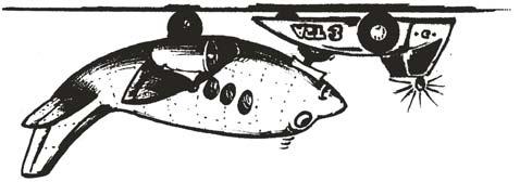
9 Description of the Chapter 2 GOTIS Page Description of the GOTIS Fig. 1 Description of the GOTIS The GOTIS monitors the torques (5) of the nose wheel. Basically, this gives more security to the customer. The steering forces are permanently measured and transmitted to a microcontroller by two load cells (7) which are incorporated in the longitudinal links (4) of the pick-up system. This microcontroller compares the current with the stored limit of the aircraft manufacturer. The system starts when the ignition of the AST is switched on. A lamp check and a check of all relevant signals is now carried out. When one or more lamps are defective, they must be replaced before starting to work with the tractor. When further errors occur during this system check, they are indicated by means of the BLUE error light which flashes accordingly and also by means of a message which appears on the TDM (See Flashing Code Table 1.1) When an aircraft is loaded, the system checks all relevant signals for correctness. In the case of no errors, the system activates the GOTIS light (green) and thus indicates operation readiness. Only from that moment, the monitoring of the torque starts working on aircraft which require an overtorque system. As long as the steering forces are not in a critical range, the lighting up of the GOTIS light (green) indicates to the driver that the system works properly. When the aircraft is unloaded again, the monitoring of the airplane stops and the GOTIS light (green) goes out.
10 Description of the Chapter 2 GOTIS Page 2 When 70% of the current limit value is reached, the driver is alerted by the flashing of a warning light (yellow) and an additional buzzer. When the steering forces are decreased, this warning will stop. An exceedence of the torque Overtorque is indicated by an additional activation of the red light and the sound of a buzzer. This alarm is maintained after unloading the airplane. This alarm can only be reset using the key switch for reset. This alarm is not stopped by switching the ignition off and on. In situations of an Overtorque (red alarm light), the user must determine and document suitable actions to be taken in accordance with SAE ARP We recommend to make these actions available to the operator/driver in the cabin as a job instruction. The measurement is interrupted when an error occurs in the system, the GOTIS light (green) goes out and the error is indicated by the error light (blue) as a flashing code (see Flashing Code Table 1.1) and also appears as a message on the TDM.
11 Maintenance of the GOTIS Chapter 3 Maintenance intervals Page Maintenance intervals of the GOTIS The following maintenance schedule contains an overview of the maintenance work and the intervals. Due to the special operating conditions of the AST, the maintenance work is broken down into one-off or several periodical maintenance services, dependent on the number of operating hours, as well as into periodical special services. The specified intervals refer to the number of operating hours displayed on the instrument panel of the engine. Before all maintenance procedures, the vehicle must be cleaned! The maintenance schedule does not include maintenance-free bearings and joints, i.e. lubricating points which are fitted with life-time lubrication, which are self-lubricating or automatically lubricated (e.g. encapsulated or supplied by the central lubrication system) or lubricating points which are lubrication-free. Basically, the user undertakes to adhere to the specified maintenance periods and the corresponding maintenance services and to enter these records in the Maintenance Chart. (Maintenance Records see WA Part 1, Chapter 4.1)

12 Maintenance of the GOTIS Chapter 4 Maintenance schedule Page Maintenance schedule It is absolutely necessary to adhere to the maintenance instructions (see Maintenance Manual Part 1, General). General Functioning, fixing and tightness of total system GOTIS lamp check Electric System 5.1 every 12 months Electric check of wiring every 12 months Electric check No.1 of load cell every 12 months Electric check No.2 of load cell every 12 months Electric check of measuring signal every 12 months Electric check of output signal on amplifier every 12 months Electric check of voltage supply on amplifier every 12 months Electric check of voltage supply of load cell every 12 months Electric check of fuse in amplifier Mechanical check of the GOTIS every 24 months or every 4000 operating hours Mechanical check of the GOTIS by means of GOTIS test tool
13 Maintenance of the GOTIS Chapter 4 Maintenance schedule Page Maintenance records GOTIS The user undertakes to always adhere to the maintenance intervals and the corresponding maintenance services and to enter these records in the following maintenance chart. Maintenance service Maintenance record carried out at...(h) Date Signature
14 Maintenance of the GOTIS Chapter 4 Maintenance schedule Page 3 Maintenance service Maintenance record carried out at...(h) Date Signature
15 Maintenance of the GOTIS Chapter 4 Maintenance schedule Page 4 Maintenance service Maintenance record carried out at...(h) Date Signature
16 Maintenance of the GOTIS Chapter 5 Maintenance work Page Maintenance work Basically, the safety regulations applicable to the control and the operation of the AST also apply to the maintenance (see Operating Manual, Primary Information Safety Instructions ). During all maintenance work on the AST, the local accident prevention regulations and other official regulations and directives must be met. Any deviation from regulations and approvals carried out by the user must in each individual case be clarified with the manufacturer. For all maintenance work to be carried out, switch off the engines, ensure non-energized state, main vehicle switch OFF, battery isolating switch OFF. The only exceptions to this ruling are formed by individual maintenance steps for adjustment and trial runs or test driving. In these cases, maintenance staff must take suitable precautions. During load tests of the hydraulic system (high pressure up to 420 bar), there is danger to life if any leakages occur within the high-pressure system. After all maintenance works and before re-starting operation of the vehicle, a functional check of all parts and a test drive must be carried out.
 light up 1time simultaneously.")
17 Maintenance of the GOTIS Chapter 5 Maintenance work Page Maintenance of the GOTIS GOTIS Lamp check Fig. 1 When the ignition of the AST is switched on, the system carries out a lamp check. When no lamps are defective, all four indicators (1-4) light up 1time simultaneously. All defective lamps must be replaced before every ride. GOTIS Lamp check
18 Maintenance of the GOTIS Chapter 5 Maintenance work Page Electric check of the GOTIS The electric check must be carried out every 2000 operating hours or yearly - whatever comes first - according to the following checklist. This ensures that the components used in the GOTIS work properly. The check of the ma-signals may only be carried out using a multimeter connected in series. A measurement between vehicle mass and ma-output causes damage to the amplifier. The checks/tests as described on the following pages are also checklists used for the maintenance. It is advisable to copy these pages before every maintenance to be carried out. During the electric check of the GOTIS, the ignition of the AST must be ON. To be able to carry out the following electric checks of the GOTIS correctly and error-free, the corresponding Electric Systems must be considered. For older versions, it may be necessary to request the suitable adapter cables from Goldhofer. If the check proves that there is a defect in the load cells, it is always necessary to replace both the load cells and the amplifiers. Load cells and amplifiers are always co-ordinated. Recommendation: The functioning must be tested with a testtool after replacement of the components. The functional test applies to replaced sets consisting of load cell and amplifier as well as to separately replaced amplifiers. To order the load cells and the amplifiers, please use the enclosed order form. Complete the form and mention the relevant nominal / actual.

19 Maintenance of the GOTIS Chapter 5 Maintenance work Page 4 Description of the adapter cable The adapter cable is required for the electric check on older tractors. This cable enables to place the occupancy of the terminal strips outwards. So, the plug connections must not be opened to carry out the check. Fig. 2 In case of a fault in the system, this adapter cable is no replacement for looking in and checking the plastic plugs (for example cable rupture within the plug). Also consider the corresponding electric systems. During that check, additionally check the plastic plugs for any damage. Adapter cable


20 Maintenance of the GOTIS Chapter 5 Maintenance work Page Electric check of the amplifier voltage supply In doing so, it can determined if the operating voltage is existing on the amplifier. Description of checks Value left vehicle side Value right vehicle side Check operating voltage of the amplifier between terminal 1 and terminal 2 NOMINAL ACTUAL NOMINAL ACTUAL Observe polarity: Red point to terminal 1 = + or red Black point to terminal 2 = - or black For the nominal of the electric check, see chapter 6. Fig. 3 Electric check of the amplifier voltage supply Fig. 4 Electric check of the amplifier voltage supply

21 Maintenance of the GOTIS Chapter 5 Maintenance work Page a Electric check of the fuse in the amplifier This check is only necessary in the case of no signal existing during the electric check in and Description of checks Functional test of fuse Value left vehicle side NOMINAL ACTUAL Value right vehicle side NOMINAL ACTUAL Fig. 5 Electric check of the fuse in the amplifier
 the operating voltage as needed by the load cell.")

22 Maintenance of the GOTIS Chapter 5 Maintenance work Page Electric check of the load cell voltage supply In doing so it can be determined if the amplifier exchanged (output) the operating voltage as needed by the load cell. Description of checks Value left vehicle side Value right vehicle side Check the operating voltage of the load cell between terminal 6 and terminal 7. Observe polarity: Red point to terminal 6 = - or black Black point to terminal 7 = + or red NOMINAL For the nominal of the electric check, see chapter 6. Fig. 6 Electric check of the load cell voltage supply ACTUAL NOMINAL ACTUAL Fig. 7 Electric check of the load cell voltage supply


23 Maintenance of the GOTIS Chapter 5 Maintenance work Page Electric check No.1 of the load cell In doing so, the internal resistance of the load cell is checked. Description of check Value left vehicle side Value right vehicle side Remove plug panel from amplifier. Measurement of resistance between + and - signal. Red wire and black wire; Terminal 6 und terminal 7 in amplifier. Observe polarity: Black point to 6 = - or black Red point to 7 = + or red NOMINAL For nominal of electric check, see chapter 6. If the are exceeded, replace the load cell and amplifiers. Fig. 8 Electric check No.1 of the load cell ACTUAL NOMINAL ACTUAL Fig. 9 Electric check No.1 of the load cell
24 Maintenance of the GOTIS Chapter 5 Maintenance work Page Electric check No. 2 of the load cell In doing so, the external resistance of the load cell is measured. Description of check Value left vehicle side Value right vehicle side Remove plug panel from amplifier. Measurement of resistance between + and - signal. White wire and green wire; Terminal 9 and 10 in amplifier. Observe polarity: Black point to 9 = - or black Red point to 10 = + or red NOMINAL For the nominal of the electric check, see section 6. If the are exceeded, replace the load cell and amplifiers. Fig. 10 Electric check No. 2 of load cell ACTUAL NOMINAL ACTUAL Fig. 11 Electric check No. 2 of load cell


25 Maintenance of the GOTIS Chapter 5 Maintenance work Page Electric check of measuring signal In doing so, the signal voltage of the load cell is measured. The pick-up device is raised empty. Description of check Value left vehicle side Value right vehicle side Check the mv-signals of the load cell on terminal 9 and 10 in the amplifier. NOMINAL ACTUAL NOMINAL ACTUAL Observe the polarity: Black point to 9 = - or black Red point to 10 = + or red For the nominal of the electric check, see chapter 6. If the are exceeded, replace the load cell and amplifiers. Fig. 12 Electric check of measuring signal Fig. 13 Electric check of measuring signal

26 Maintenance of the GOTIS Chapter 5 Maintenance work Page Adjustment and electric check of the amplifier output signal In doing so, the output signal of the amplifier in ma is checked. Description of check Value left vehicle side Value right vehicle side Green wire disconnected from terminal 3. Check ma-signals of amplifier on terminal 3 in amplifier. Observe polarity: Red point to terminal 3 Black point to green wire = + or red = - or black NOMINAL For the nominal of the electric check, see chapter 6. Instructions to adjust the amplifier see Index ACTUAL NOMINAL ACTUAL Fig. 14 Electric check of the amplifier output signal
27 Maintenance of the GOTIS Chapter 5 Maintenance work Page Amplifier Readjustment potentiometer in the amplifier. If the value in test step is out of the nominal value, it can be readjusted by means of the potentiometer (see arrow). Turn the potentiometer slowly and with caution. After adjustment /turning the potentiometer, wait for 5 to 10 seconds to get the stabilised value. (Control mode of the amplifier) Fig. 15 Amplifier
: 1.")
 and carrier of pull arms (4) on the ground and fix it with bolt (5) and safety pin. Fig.")
28 Maintenance of the GOTIS Chapter 5 Maintenance work Page Mechanical check of GOTIS using the GOTIS test tool Installation of the GOTIS test tool Working steps to install the GOTIS test tool (1-7): 1. Remove roller supports from pull arms. Fig Install crossbeam (1) of test tool between the vehicle frame and fix it with bolts (2). Fig. 17 Working steps Installation of GOTIS test tool Working steps Installation of GOTIS test tool 3. Assemble thrust rod (3) and carrier of pull arms (4) on the ground and fix it with bolt (5) and safety pin. Fig. 18 Working steps Installation of GOTIS test tool
 - Observe the correct mounting position. Fig. 19 Fig.")
 must not yet be fixed. 6. Connect pressure gauge (400 bar) to measuring point on the piston side (MP-K) of the hydraulic cylinder (6). 7.")
29 Maintenance of the GOTIS Chapter 5 Maintenance work Page Install thrust rod (3) and carrier of pull arms (4) in the pick-up device using a suitable auxiliary tool. (Weight approx. 150 kg) - Observe the correct mounting position. Fig. 19 Fig. 20 Working steps Installation of GOTIS test tool Working steps Installation of GOTIS test tool 5. Install the hydraulic cylinder (6) in the test tool. Bolt (8) must not yet be fixed. 6. Connect pressure gauge (400 bar) to measuring point on the piston side (MP-K) of the hydraulic cylinder (6). 7. Ensure the hydraulic supply of the hydraulic cylinder (6). (External supply). Fig. 21 Working steps Installation of GOTIS test tool
30 Maintenance of the GOTIS Chapter 5 Maintenance work Page Mechanical check of GOTIS Working steps - Check GOTIS (1-5): All aircraft types must be tested which the built-in Gotis-system is activated for. Exact information about the activated aircraft models can be obtained from the user/operating authority. The mechanical check must be carried out on the basis of the GOTIS- reference. (see Reference Values Table 5.1.5). Example: If the GOTIS check is carried out for an aircraft type B767, a 120 mm thrust part must be installed in the pull arms. In the example given, the yellow lamp must light up and the buzzer be activated when a pressure of 76 ± 3 bar is reached (70% of the maximum permissible torque is reached). When achieving a pressure of 106 ± 3 bar, the red lamp must light up and a buzzer be activated (100% of the maximum permissible torque is reached). 1. Fit the thrust parts (7) which correspond to the AST and the aircraft in the pull arms and retract the pull arms slowly. 2. Fix bolt (8) of the hydraulic cylinder. (See Fig. 21) 3. Simulate the switching point of the sensor BA26 / BA27 using a suitable auxiliary tool. 4. Lift the pick-up device using the control lever on the seat console Working step 5 is only applicable to AST-1 / AST-2 (for AST-3, see working steps 6-9) 5. Switch over calibration switch SS09 in control box X39.
 6. Select the menu point SERVICE in the main menu of the TDM and confirm with ENTER. 7.")

31 Maintenance of the GOTIS Chapter 5 Maintenance work Page 16 Working steps 6-9 are only for AST-3 (Depressurise hydraulic cylinders (6), set workshop switch SP02- X 35 to ON position) 6. Select the menu point SERVICE in the main menu of the TDM and confirm with ENTER. 7. Select the menu point GOTIS and confirm with ENTER. 8. Select the menu point SYSTEM-CHECK and confirm with ENTER. 9. Select the menu point OVTCHECK and change from OFF to ON by means of button 5 and confirm with ENTER. Fig. 22 Working step 6 Fig. 23 Working step 7 Fig. 24 Working step 8 Fig. 25 Working step 9 Fig. 26 Working step 9

32 Maintenance of the GOTIS Chapter 5 Maintenance work Page Pressurise hydraulic cylinder with respective pressure and carry out check. For reference, see GOTIS Reference Value Table, Index The pressure build-up of the hydraulic supply has to be 3 to 10 bars. The flashing-up of the lamp and the sound of the buzzer are temporally delayed due to the control mode. If the signal is not released after reaching the reference value, the mechanical check must be repeated 3 times more. In doing so, the test pressure must be gradually increased by 2 bar. The required end-test pressure must be put down in the test report, index and sent to Goldhofer. Working step 11 is only for AST-1 / AST-2 (for AST-3, see working steps 6-9. Working step 9 is now not from OFF to ON, but from ON to OFF ). 11. Reset calibration switch SS09 to initial position. (See also working step 5) 12. Remove bolt (8) of the hydraulic cylinder (6). - Before removal of the pin, decrease the hydraulic pressure in the cylinder Fig. 27 Working steps Installation of GOTIS test tool 13. Reset GOTIS with key switch (5) in driver s cabin (see chapter 1.0) 14. Decrease pressure in the pull arms (Extend pull arms by approx cm). Fig. 28 Overview of monitoring and control elements GOTIS Open the pull arms only so far that the swivel arms cannot swing out! 15. Remove the auxiliary tool simulating the switching BA26 / BA Check next aircraft (Repeat working steps 1-15).
33 Maintenance of the GOTIS Chapter 5 Maintenance work Page GOTIS - Reference Value Table AST - 1 Aircraft type Length of thrust part Hydraulic pressure for 70% of the maximum permissible torque (yellow lamp + buzzer) Hydraulic pressure for 100% of the maximum permissible torque (red lamp + buzzer) B mm 76 ± 2 bar 106 ± 2 bar A330/ / mm 94 ± 2 bar 132 ± 3 bar B mm 110 ± 3 bar 160 ± 4 bar A / mm 126 ± 3 bar 178 ± 5 bar AST - 2 Aircraft type Length of thrust part Hydraulic pressure for 70% of the maximum permissible torque (yellow lamp + buzzer) Hydraulic pressure for 100% of the maximum permissible torque (red lamp + buzzer) B mm 26 ± 2 bar 40 ± 2 bar B mm 68 ± 2 bar 96 ± 3 bar B mm 86 ± 3 bar 124 ± 4 bar A / mm 118 ± 3 bar 168 ± 4 bar B mm 136 ± 4 bar 196 ± 5 bar AST - 3 Aircraft type Length of thrust part Hydraulic pressure for 70% of the maximum permissible torque (yellow lamp + buzzer) Hydraulic pressure for 100% of the maximum permissible torque (red lamp + buzzer) B mm 28 ± 2 bar 42 ± 2 bar B mm 75 ± 3 bar 108 ± 3 bar B mm 100 ± 3 bar 138 ± 4 bar If the signal is not released after reaching the reference value, the mechanical check must be repeated 3 times more. In doing so, the test pressure must be gradually increased by 2 bar. The required end-test pressure must be put down in the test report, index and sent to Goldhofer.
34 Maintenance of the GOTIS Chapter 5 Maintenance work Page Test report Reached pressure 70% torque Reached pressure 100% torque NOMINAL ACTUAL NOMINAL ACTUAL AST 1 B 767 A330/ /-300 B 777 A /-600 NOMINAL ACTUAL NOMINAL ACTUAL AST 2 B 737 B 757 B 767 A330/ /-300 B 777 NOMINAL ACTUAL NOMINAL ACTUAL AST 3 B 737 B 757 B 762
35 Maintenance of the GOTIS Chapter 6 Electric setting of the GOTIS Page Electric setting of the GOTIS AST-1 / AST-2 Electric check left vehicle side NOMINAL right vehicle side NOMINAL Electric check of the amplifier voltage supply V V Electric check of the load cell voltage supply 10 ± 0,2 V 10 ± 0,2 V Electric check No. 1 of the load cell 750±30Ohm 750±30Ohm Electric check No. 2 of the load cell Serial-No. > LL see appendix A Electric check No. 2 of the load cell Serial-No. > LL ±20Ohm Serial-No. > LL ±20Ohm Electric check of measuring signal 0,0 ± 1,5 mv 0,0 ± 1,5 mv Electric check of the amplifier output signal 15 ± 1,5 ma 15 ± 1,5 ma AST-3 (not AST-3 R) Electric check left vehicle side NOMINAL right vehicle side NOMINAL Electric check of the amplifier voltage supply V V Electric check of the load cell voltage supply 10 ± 0,2 V 10 ± 0,2 V Electric check No. 1 of the load cell 750±30Ohm 750±30Ohm Electric check No. 2 of the load cell Serial-No. > LL see appendix A Electric check No. 2 of the load cell Serial-No. > LL ±20Ohm Serial-No. > LL ±20Ohm Electric check of measuring signal 0,0 ± 1,5 mv 0,0 ± 1,5 mv Electric check of the amplifier output signal 12 ± 1,5 ma 12 ± 1,5 ma If the ACTUAL deviate from the NOMINAL, you must observe the Troubleshout-List in Chapter 7.0.
36 Maintenance of the GOTIS Chapter 7 Troubleshoot List Page Troubleshoot List AST-1/-2/-3 (CAN-Bus with blue light) Flashing code of blue light Type of error Cause Trouble-shooting 2x START ERROR Short break in current during vehicle operation to PLC AP07 1. Ignition off/on 2. Check current supply of AP07 3x CAN_RX_ERROR Trouble in data transmission to AP07 1. Ignition off/on 2. Check wiring of CAN-bus 4x CAN_TX_ERROR Trouble in data transmission to AP07 1. Ignition off/on 2. Check wiring of CAN-bus 5x KEY SWITCH_ERROR Key switch in wrong position Set key switch to 0 position 6x A/C-CLASSIFIC. FAILED 1. Wrong selection of tractive power stage 2. Nosewheel diameter too small / too large for selected tractive power stage 3. Nosewheel diameter deviations from determined range 7x ZERO LEVEL_ERROR Tractor-aircraft combination was moving during loading procedure 1. Select correct tractive power stage 2. Check sensor BA49 / BA50 3. Recalibrate sensor BA49 / BA50 9x HW-ERROR (EEPROM_RD) Eeprom read error Replace PLC AP07 10x HW-ERROR (EEPROM_WR) Eeprom write error Replace PLC AP07 Activate parking brake, press ESC-button on TDM and reconfirm tractive power stage
37 Maintenance of the GOTIS Chapter 7 Troubleshoot List Page 2 12x CABLE RUPT. BS01 (LL le) ma-signal on X35:xxx or X40.7:xxx < 0,2 ma xxx stands for the corresponding terminal as per the Electric System 13x BS01 DEFECT. (LL le) ma-signal on X35:xxx or X40.7:xxx > 25mA xxx stands for the corresponding terminal as per the Electric System 14x CABLE RUPT. BS02 (LL ri) ma-signal on X35:xxx or X40.7:xxx <0,2 ma xxx stands for the corresponding terminal as per the Electric System 1. Check voltage supply on left amplifier (AS03) (see ); between AS03:1 and AS03:2 Þ 24V 2. Check ma-signal on amplifier (see ); AS03:3 Þ AST-1/-2 = 15 ± 1,5 ma; AST-3F = 12 ±2mA 3. Check supply voltage of strain gauge (see ); between AS03:6 and AS03:7 Þ 10 ± 0,1V 4. Check fuse in amplifier (see ) 5. Ohmic check of cable harness W Defective amplifier - Replace 1. Check wiring BS01 (left load cell) to AS03 (left amplifier) 2. Check supply voltage of strain gauge (see ); between AS03:6 and AS03:7 Þ 10 ± 0,1V 3. Check signal voltage of strain gauge (see ); between AS03:9 and AS03:10 Þ 0 ± 1,5 mv 4. Measure resistance of strain gauge: Draw plug out of amplifier, between AS03:6 and AS03:7 Þ 750 ± 30 Ohm (see ); between AS03:9 and AS03:10 Þ 700 ± 20 Ohm (see ) 5. Replace load cell and amplifier 1. Check voltage supply on right amplifier (AS04) (see ); between AS04:1 and AS04:2 Þ 24V 2. Check ma-signal on amplifier (see ); AS04:3 Þ AST-1/-2 = 15 ± 1,5 ma; AST-3F = 12 ±2mA 3. Check supply voltage of strain gauge (see ); between AS04:6 and AS04:7 Þ 10 ± 0,1V 4. Check fuse in amplifier (see ) 5. Ohmic check of cable harness W Defective amplifier - Replace
38 Maintenance of the GOTIS Chapter 7 Troubleshoot List Page 3 15x BS02 DEFECT (LL ri) ma-signal on X35 or X40.7 > 25 ma 1. Check wiring BS02 (right load cell) to AS04 (right amplifier) 2. Check supply voltage of strain gauge (see ); between AS04:6 and AS04:7 Þ 10 ± 0,1V 3. Check signal voltage of strain gauge (see ); between AS04:9 and AS04:10 Þ 0 ± 1,5 mv 4. Measure resistance of strain gauge: Draw plug out of amplifier, between AS04:6 and AS04:7 Þ 750 ± 30 Ohm (siehe ); between AS04:9 and AS04:10 Þ 700 ± 20 Ohm (see ) 5. Replace load cell and amplifier
39 Order form Page 1 Amplifier Order Form Vehicle type Vehicle number Vehicle side / Serial No. of the load cells Measuring Nominal / Actual Measuring Nominal / Actual Measuring Nominal / Actual Adress of delivery Please fax this order form to our Service Department Airport Equipment. Fax no. (+49) Fax no. (+49) Fax no. (+49) Fax no. (+49) Fax no. (+49) / / /
40 Appendix Page 1 Appendix A Depending on the batch, load cells with a serial number > LL 12000" have different external resistances. In the case of replacement of a load cell, you have to compare the serial number with the table below. All serial numbers > LL 15000" are provided with an additional character N ( standardised"). All these load cells have an external resistance of 800 +/- 20 Ohm. Replacement (AT) - Load cells after repair: If the strain gauge is replaced in a load cell, the character N will be added to the serial number after repair. These load cells will then also have an external resistance of 800 +/-20 Ohm. 700 ± 30 Ohm 800 ± 20 Ohm LL LL LL LL LL LL LL LL LL rsi / Goldhofer Aktiengesellschaft Donaustraße Memmingen BA Part 1/3
41 GOTIS Index pictures Page 1 Index Name Chapter - Page Index pictures The GOTIS documentation AST-1, AST-2, AST-3 (not AST-3 R) Use according to purpose 1.0 Overview of monitoring elements and controls of the GOTIS 1-1 Fig. 1 Overview of monitoring elements and controls of the GOTIS 1-1 Fig. 2 Overview of monitoring elements and controls of the GOTIS Flashing code table for diagnosis Approvals 1-4 Fig. 3 Approvals Description of the GOTIS 2-1 Fig. 1 Description of the GOTIS Maintenance intervals of the GOTIS Maintenance schedule Maintenance records GOTIS Maintenance work Maintenance of the GOTIS 5-2 Fig. 1 GOTIS Lamp check 5-2 Fig. 2 Adapter cable 5-4 Fig. 3 Electric check of the amplifier voltage supply 5-5 Fig. 4 Electric check of the amplifier voltage supply 5-5 Fig. 5 Electric check of the fuse in the amplifier 5-6 Fig. 6 Electric check of the load cell voltage supply 5-7 Fig. 7 Electric check of the load cell voltage supply 5-7 Fig. 8 Electric check No.1 of the load cell 5-8 Fig. 9 Electric check No.1 of the load cell 5-8 Fig. 10 Electric check No. 2 of load cell 5-9 Fig. 11 Electric check No. 2 of load cell 5-9 Fig. 12 Electric check of measuring signal 5-10 Fig. 13 Electric check of measuring signal 5-10 Fig. 14 Electric check of the amplifier output signal 5-11 A A
42 GOTIS Index pictures Page 2 Index Name Chapter - Page Fig. 15 Amplifier 5-12 Fig. 16 Working steps Installation of GOTIS test tool 5-13 Fig. 17 Working steps Installation of GOTIS test tool 5-13 Fig. 18 Working steps Installation of GOTIS test tool 5-13 Fig. 19 Working steps Installation of GOTIS test tool 5-14 Fig. 20 Working steps Installation of GOTIS test tool 5-14 Fig. 21 Working steps Installation of GOTIS test tool 5-14 Fig. 22 Working step Fig. 23 Working step Fig. 24 Working step Fig. 25 Working step Fig. 26 Working step Fig. 27 Fig. 28 Working steps Installation of GOTIS test tool 5-17 Overview of monitoring and control elements GOTIS Electric setting of the GOTIS Troubleshoot List AST-1/-2/-3 (CAN-Bus with blue light) 7-1 Amplifier Order Form 8-1 Appendix A 9-1
TRAIL-Control - Manufacturer -
 Installation and Operating Instructions TRAIL-Control - Manufacturer - Release 03-2001 Müller Elektronik GmbH & Co. KG Franz-Kleine-Str. 18 33154 Salzkotten Datei: 302901-02_E(ME015488)_PDF.DOC Contents
16 37 TM INTEGRATED RADIO CONTROL INSTRUCTION MANUAL
 16-37 TM IRC Instruction Manual (99903542) 16 37 TM INTEGRATED RADIO CONTROL INSTRUCTION MANUAL 01.01 2007 IOWA MOLD TOOLING CO., INC. GARNER, IA 50438 1. Introduction... 2 2. The Components of the IRC-System...
IVTM Installation Manual
 Integrated Vehicle Tire Pressure Monitoring IVTM Installation Manual 2nd edition Copyright WABCO 2006 Vehicle Control Systems An American Standard Company The right of amendment is reserved Version 002/06.06(us)
Perfusor Space. Service Manual
 0-12 Perfusor Space Service Manual Version 3.0 English This document is not a complete Service Manual. It only encompasses the pages that describe how to determine the age and how to check the condition
Exterior Digital Load Scale 201-EDG-01(B) Installation and Operation Manual Please read carefully before installation
 Installation and Operation Manual Please read carefully before installation") Exterior Digital Load Scale 201-EDG-01(B) Installation and Operation Manual Please read carefully before installation 2 Exterior Digital Load Scale 201-EDG-01(B) Table of Contents Specifications & Overview
Exterior Digital Load Scale 201-EDG-01(B) Installation and Operation Manual Please read carefully before installation 2 Exterior Digital Load Scale 201-EDG-01(B) Table of Contents Specifications & Overview
Section 3 Technical Information
 Section 3 Technical Information In this Module: Engine identification Modes of operation Battery charging and heat manage operation Service and repair procedures Maintenance requirements Engine Identification
Control unit for Strip Thickness Gauges with nominal size setting by stepper motor Operating Instructions
 Control unit for Strip Thickness Gauges with nominal size setting by stepper motor FS4-PLC Operating Instructions FS4P-E1 erstellt am 15.4.2002 freigegeben am Bemerkungen Rev.1 Seiten: Name: Rietdorf Name:
HIGH TECH SECURES YOUR FUTURE SBA 1200 GB SUN BRAKE ANALYSER. Operating Manual
 HIGH TECH SECURES YOUR FUTURE SUN BRAKE ANALYSER Operating Manual 2 Operating Manual SUN BRAKE ANALYSER Copyright December 2009 Snap-on Equipment GmbH All rights reserved Part number: 2000618380 Rev: 3
SAFETY- FLY 700 P USER MANUAL FLYING INSTRUMENT FOR ULTRALIGHT AIRCRAFTS NR MIT
 SAFETY- FLY 700 P FLYING INSTRUMENT FOR ULTRALIGHT AIRCRAFTS NR.1017.2 MIT USER MANUAL UK Manufacturer Preface : MC elettronica S.r.l. Address : Via E. fermi, 450/486 Fiesso Umbertiano (ROVIGO) - ITALY
Removing and installing dash panel insert
 Removing and installing dash panel insert Caution To disconnect and connect the battery, the procedure described in the workshop manual should be strictly adhered to Chapter. Note Pull off multi-pin connector
Te 803 Electronic Controller. Service, Operation & Technical Information Manual
 Te 803 Electronic Controller Service, Operation & Technical Information Manual WARNING! Technical descriptions and data given in this document are accurate, to the best of our knowledge, but can be subject
OPERATION MANUAL Common for All models Bobbin Sensor (Weft End Detection) DP150 - L2 BP150 - L2-12V BP150 - L2-24V (PNP/NPN)
 DP150 - L2 BP150 - L2-12V BP150 - L2-24V (PNP/NPN)") OPERATION MANUAL Common for All models Bobbin Sensor (Weft End Detection) DP150 - L2 BP150 - L2-12V BP150 - L2-24V (PNP/NPN) Beta Computronics pvt. Ltd. 10/1 IT Park, Parsodi, Nagpur-440022 (MS), INDIA.
OPERATION MANUAL Common for All models Bobbin Sensor (Weft End Detection) DP150 - L2 BP150 - L2-12V BP150 - L2-24V (PNP/NPN) Beta Computronics pvt. Ltd. 10/1 IT Park, Parsodi, Nagpur-440022 (MS), INDIA.
ABB i-bus EIB EIB Power Supply Units SV/S SV/S SU/S
 Product Manual ABB i-bus EIB EIB Power Supply Units SV/S 30.320.5 SV/S 30.640.5 SU/S 30.640. Intelligent Installation Systems Contents Page EIB Power Supply Units. Introduction.........................................
Installation and operating instructions. Solar charge controller MPPT 10 A / 20 A Z Z
 Installation and operating instructions Solar charge controller MPPT 10 A / 20 A EN 1 Contents 1. About these instructions... 3 1.1 Applicability... 3 1.2 Users... 3 1.3 Description of symbols... 3 2.
Storage, operating and maintenance instructions for AZ plug valves and Standard valves
 ARMATUREN Plug - Valves metallic with PTFE Sleeve 2-7 way Storage, operating and maintenance instructions for AZ plug valves and Standard valves Plug - Valves FEP/PFA - lined, 2-3 way Butterfly - Valves
The function of this Dynamic Active Probe has divided into three preferences on the screen main Menus:
 1.0 Introduction: This probe is designed to provide an additional help to automotive technicians in trouble shooting of electrical circuits problems in the car. Apart from using the normal multi tester,
SI AT A22. English. Printed: Doc-Nr: PUB / / 000 / 01
 SI AT A22 English 1 Information about the documentation 1.1 About this documentation Read this documentation before initial operation or use. This is a prerequisite for safe, trouble-free handling and
Commander 15i Container and Pallet Loader. Property of American Airlines
 Commander 15i Container and Pallet Loader Section 2. Operation BEFORE ATTEMPTING TO OPERATE OR MAINTAIN THE VEHICLE, COMPLETELY READ AND UNDERSTAND THE OPERATION AND MAINTENANCE MANUAL, INCLUDING ALL DANGER,,
AIRTRONIC / AIRTRONIC M Troubleshooting and Repair Instructions
 AIRTRONIC / AIRTRONIC M Troubleshooting and Repair Instructions Airtronic Order no. Airtronic D2, 12 V 25 2069 05 00 00 Airtronic D2, 24 V 25 2070 05 00 00 Airtronic D2 Camper, 12 V 25 2326 05 00 00 Complete
SI AT A22. English. Printed: Doc-Nr: PUB / / 000 / 03
 SI AT A22 English 1 Information about the documentation 1.1 About this documentation Read this documentation before initial operation or use. This is a prerequisite for safe, trouble-free handling and
Operating instructions Platform/floor scales
 KERN & Sohn GmbH Ziegelei 1 D-72336 Balingen email: info@kern-sohn.com Phone: +49-[0]7433-9933-0 Fax: +49-[0]7433-9933-149 Internet: www.kern-sohn.com Operating instructions Platform/floor scales KERN
Operating instruction and technical description
 Operating instruction and technical description EV Simulator for charging devices with charging plug / charging coupler / charging cable type 1 and type 2 as service case Photo: EV simulator/tester with
Metrohm E3640 FLASH TESTER INSTRUCTION MANUAL. Martindale Electric Co Ltd.
 Metrohm Martindale Electric Metrohm House, Imperial Park, Imperial Way, Watford, Hertfordshire, WD24 4PP, UK T: 01923 441717 F: 01923 446900 Email: sales@martindale-electric.co.uk web: www.martindale-electric.co.uk
MB A 12V/24V DC PROGRAMMABLE DUAL BATTERY ISOLATOR
 MB-3688 120A 12V/24V DC PROGRAMMABLE DUAL BATTERY ISOLATOR User Manual Warning and Precautions MB-3688 is built with corrosion resistant material and the main electronic assembly is well sealed inside
WATERFLUX 3070 Quick Start
 WATERFLUX 3070 Quick Start Battery powered electromagnetic water meter Electronic Revision ER 4.3.0_ up to ER 4.3.4_ (SW.REV 4.2.2_ up to 4.2.5_) KROHNE CONTENTS WATERFLUX 3070 1 Safety instructions 4
Auto-Level Troubleshooting (Old Platform) Electronic Control- Prior to 2009, Pressure Switch Control panel #s 2057, 2058, 2795, 2795B
 Electronic Control- Prior to 2009, Pressure Switch Control panel #s 2057, 2058, 2795, 2795B") Auto-Level Troubleshooting (Old Platform) Electronic Control- Prior to 2009, Pressure Switch Control panel #s 2057, 2058, 2795, 2795B This guide addresses the troubleshooting of electronic controls used
Auto-Level Troubleshooting (Old Platform) Electronic Control- Prior to 2009, Pressure Switch Control panel #s 2057, 2058, 2795, 2795B This guide addresses the troubleshooting of electronic controls used
LIPPERTCOMPONENTS, INC.
 LIPPERTCOMPONENTS, INC. SCHWINTEK INWALL SLIDEOUT SYSTEM OPERATION AND SERVICE MANUAL Contents I. Controls 1-1 System components 1 1-1A versions C1 & C2 2 1-2 Motor wiring harness connections 3 1-3 Extend
Operating instructions
 Operating instructions Digital tank contents indicator DTA 10 DTA 10 DTA 10 0 4.0 m fuel oil 0 3.5 m water Read instructions before using device! Observe all safety information! Keep instructions for future
MODEL 422 Submersible Pump Controller
 MODEL 422 Submersible Pump Controller Monitors True Motor Power (volts x current x power factor) Detects Motor Overload or Underload Operates on 120 or 240VAC, Single-phase or 3-phase Built-in Trip and
Centralised Traffic Control System - Rules 1 to 17
 Centralised Traffic Control System - Rules 1 to 17 Applicability VIC Publication Requirement External Only Document Status Issue/Revision # Effective from 2 13 May 2012 0 04 October 2015 Australian Rail
Subject Underhood G System Error Codes and Symptoms System or Parts affected
 System or Parts affected Index Underhood70G (V90Gxxx) System or Parts affected... 1 Overview... 1 Identifying your System... 1 Retrieving Logged Error Messages... 1 Error Messages... 3 Error Message Table...
Installation and Operation Instructions. VAG ROTOP Portable Electric Drive
 Installation and Operation Instructions VAG ROTOP Portable Electric Drive KAT-B 5551 Edition 1-01/2018 Content 1 General 3 1.1 Safety 3 1.2 Proper use 3 2 Transport and Storage 3 2.1 Transport 3 2.2 Storage
PolyStat Immersion Circulators
 PolyStat Immersion Circulators Manual P/N U00988 Rev. 06/09/08 Instruction and Operation Manual PolyStat Immersion Circulator Table of Contents Preface Safety Compliance... 2 Unpacking... 2 Warranty...
The RCS-6V kit. Page of Contents. 1. This Book 1.1. Warning & safety What can I do with the RCS-kit? Tips 3
 The RCS-6V kit Page of Contents Page 1. This Book 1.1. Warning & safety 3 1.2. What can I do with the RCS-kit? 3 1.3. Tips 3 2. The principle of the system 2.1. How the load measurement system works 5
GENUINE PARTS INSTALLATION INSTRUCTIONS
 GENUINE PARTS INSTALLATION INSTRUCTIONS 1 DESCRIPTION: 2 APPLICATION: 3 PART NUMBER(S) REQUIRED FOR INSTALLATION: 4 KIT CONTENTS: Remote Engine Starter Murano 2015 ~ S grade only 999K1 C3000 (Remote Engine
VC-4820 Programmable DC-DC Converter with Battery Charger function USER'S MANUAL
 1. INTRODUCTION VC-4820 Programmable DC-DC Converter with Battery Charger function USER'S MANUAL This MCU controlled Step Down DC-DC Converter has a digitally adjustable output in 0.2V increments. This
Operating Instructions for Elevator Buffers type LP
 Operating Instructions for Elevator Buffers type LP 1 Scope of application The Elevator Buffer type LP is an energy dissipation type buffer according to EN 81-1/2, EN 81-20, EN 81-50 5.5 and therefore
Product Guide: Series III Pump Control Board Set (RoHS)
") revised 04/08/10 Description: The Series III Pump Control Board Set provides motor drive and pump control for a wide assortment of pumps from Scientific Systems, Inc. The assembly consists of two circuit
revised 04/08/10 Description: The Series III Pump Control Board Set provides motor drive and pump control for a wide assortment of pumps from Scientific Systems, Inc. The assembly consists of two circuit
SOLAR LIGHTING CONTROLLER SUNLIGHT MODELS INCLUDED IN THIS MANUAL SL-10 SL-10-24V SL-20 SL-20-24V
 SOLAR LIGHTING CONTROLLER OPERATOR S MANUAL SUNLIGHT MODELS INCLUDED IN THIS MANUAL SL-10 SL-10-24V SL-20 SL-20-24V 10A / 12V 10A / 24V 20A / 12V 20A / 24V 1098 Washington Crossing Road Washington Crossing,
Time Electronics DC Voltage Calibrator. Technical Manual
 Time Electronics 1010 DC Voltage Calibrator Technical Manual V1.1 20/04/09 Time Electronics Ltd Botany Industrial Estate, Tonbridge, Kent, TN9 1RH Tel: +44(0)1732 355993 Fax: +44(0)1732 770312 Email: mail@timeelectronics.co.uk
Attitude And Direction
 CIRRUS AIRPLANE MAINTENANCE MANUAL Attitude And Direction CHAPTER 34-20: ATTITUDE AND DIRECTION GENERAL 34-20: ATTITUDE AND DIRECTION 1. General This section contains information pertaining to those portions
1200+ WITH LVD (LOW VOLTAGE DISCONNECT) USER GUIDE
 USER GUIDE") 1200+ WITH LVD (LOW VOLTAGE DISCONNECT) USER GUIDE INST045 Doc 2.00 CONTENTS General Information...2 Operating Environment...6 Features...7 Installation Instructions...8 Inverter Ground and Remote Sense
1200+ WITH LVD (LOW VOLTAGE DISCONNECT) USER GUIDE INST045 Doc 2.00 CONTENTS General Information...2 Operating Environment...6 Features...7 Installation Instructions...8 Inverter Ground and Remote Sense
LS0512R Solar Light Controller
 LandStar LS0512R Solar Light Controller Nominal system voltage Maximum PV input voltage Nominal charge / discharge current 12VDC 35V 5A Contents 1 Important Safety Information... 1 2 General Information...
4745 Drill OWNER'S MANUAL (06-08) #
 #") 4745 Drill OWNER'S MANUAL (06-08) # 605865 Identification Your CrustBuster drill is identified by a Serial Number and Model Number. Record these numbers in the spaces provided in this manual and refer
4745 Drill OWNER'S MANUAL (06-08) # 605865 Identification Your CrustBuster drill is identified by a Serial Number and Model Number. Record these numbers in the spaces provided in this manual and refer
User's Manual. MV100 Rechargeable Battery Model. Yokogawa Electric Corporation. IM MV100-41E 1st Edition
 User's Manual MV100 Rechargeable Battery Model Yokogawa Electric Corporation 1st Edition Thank you for purchasing the MV100 Rechargeable Battery Model. This user s manual describes the rechargeable batteries.
victron energy B L U E P O W E R
 victron energy Bus-based power distribution system Installation & Operation manual VE.NET DC victr on ener gy Installation & operation manual Copyrights 2006 Victron Energy B.V. All Rights Reserved This
Technical Documentation
 Technical Documentation Product manual Holding brake controller Document: 0198441113316 Edition: V1.00, 03.2006 Important information The drive systems described here are products for general use that
ZB0050 / ZB0051 ZB0070 / ZB0071
 Operating instructions Safety Rope Emergency Stop Switches UK ZB0050 / ZB0051 ZB0070 / ZB0071 7390877 / 02 08/2013 Contents 1 Safety instructions...3 2 Installation / set-up...4 2.1 Applications...4 2.2
MODEL 520 REMOTE START ENGINE MANAGEMENT SYSTEM
 MODEL 520 REMOTE START ENGINE MANAGEMENT SYSTEM DSE 520 ISSUE 4 4/4/02 MR 1 TABLE OF CONTENTS Section Page INTRODUCTION... 4 CLARIFICATION OF NOTATION USED WITHIN THIS PUBLICATION.... 4 1. OPERATION...
Diesel Locomotive Train Driver Performance Checklist
 Diesel Locomotive Train Driver Performance Checklist (Generic Version) Version 1 June, 2011 IMPORTANT NOTICE This booklet is one of a series of generic training and assessment templates developed by the
Contents Copyright...2 General advice...2 Safety instructions...3 References of legal regulations for operation...3 Space of delivery for 37998, 37998
 Version 1.05 (22.02.2013) Installation instruction Parking assist Front + Rear Article no.37998, 37998-1, 37998-2 39745 VW Touareg 7P www.kufatec.de Kufatec GmbH & Co. KG Dahlienstr. 15 23795 Bad Segeberg
Instruction Manual for the 110 VAC Draw-off Controller System
 1 Instruction Manual for the 110 VAC Draw-off Controller System Introduction This Electronic Draw-off Controller is specifically designed for use in the Maple syrup industry. It has several features designed
Mounting and operating instructions EB 5801 EN. Electric Actuators Type 5801 (Rotary Actuator) Type 5802 (Linear Actuator)
 Type 5802 (Linear Actuator)") Electric Actuators Type 5801 (Rotary Actuator) Type 5802 (Linear Actuator) Linear Actuator with Type 3260 Control Valve Rotary actuator with lever system Linear actuator with Type 3321 (V2001) Control
Electric Actuators Type 5801 (Rotary Actuator) Type 5802 (Linear Actuator) Linear Actuator with Type 3260 Control Valve Rotary actuator with lever system Linear actuator with Type 3321 (V2001) Control
Operation Manual for Torque Sensors
 Operation Manual for Torque Sensors For below and similar Types DV-14 DH-15 D-2431 DFW-25 DFW-35 D-2223 D-2268 D-2209 DF-30 D-2553 Page 1 of 11 Imprint LORENZ MESSTECHNIK GmbH Manufacturer, Place Lorenz
Electronic Ballast EVG 2000-T
 Electronic Ballast EVG 2000-T Operating Manual Table of contents 1 Description 1.1 Advantages of this ballast... 3 1.2 Functional principle... 3 1.3 Energization... 4 1.4 Visualization... 5 1.5 Indications
HP21 SERVICE SUPPLEMENT UNIT INFORMATION. TSC6 Two-Speed Control
 SERVICE UNIT INFORMATION SUPPLEMENT HP21 Corp. 9426 L10 Litho U.S.A. All HP21-4 and -5 units (single and three phase) are equipped with a TSC6 two-speed control. The TSC6 (A14) two-speed control contains
User Manual. Solar Charge Controller 3KW
 User Manual Solar Charge Controller 3KW 1 CONTENTS 1 ABOUT THIS MANUAL... 3 1.1 Purpose... 3 1.2 Scope... 3 1.3 SAFETY INSTRUCTIONS... 3 2 INTRODUCTION... 4 2.1 Features... 4 2.2 Product Overview... 5
R & D SPECIALTIES ROTROL I USER'S MANUAL
 R & D SPECIALTIES ROTROL I USER'S MANUAL TABLE OF CONTENTS INTRODUCTION...2 SPECIFICATIONS...2 CONTROLS AND INDICATORS...3 TIME DELAYS...4 INSTALLATION...5 SYSTEM OPERATION...9 TROUBLESHOOTING...13 OPTIONAL
CEMLINE CORPORATION P. O. BOX 55 CHESWICK, PENNSYLVANIA Phone: (724) FAX (724)
 FAX (724)") Installation, Operation, and Maintenance Manual CEMLINE CORPORATION Electronic Controls for Water Heaters with RWD45U Controller CEMLINE CORPORATION P. O. BOX 55 CHESWICK, PENNSYLVANIA 15024 Phone: (724)
Installation, Operation, and Maintenance Manual CEMLINE CORPORATION Electronic Controls for Water Heaters with RWD45U Controller CEMLINE CORPORATION P. O. BOX 55 CHESWICK, PENNSYLVANIA 15024 Phone: (724)
CURTIS TOLEDO. AF Series Compressors VS models with VFD WARNING
 AUGUST, 2004 REV.A CURTIS TOLEDO OPERATOR S MANUAL SUPPLEMENT AF Series Compressors VS models with VFD WARNING Personal injury and/or equipment damage will result by failing to pay attention to the vital
CRUISE CONTROL SYSTEM
 CRUISE CONTROL SYSTEM 1994 Toyota Celica 1994 ACCESSORIES & EQUIPMENT Toyota Motor Sales, U.S.A., Inc. - Cruise Control Systems Celica DESCRIPTION Cruise control system consists of Cruise Control Electronic
Installation & Calibration
 Installation & Calibration ED2-AT Series SkidWeigh System Lift Truck On-board Check Weighing With Accumulative Load Weight Total ED2-AT Series SkidWeigh V.1.1 General Installation Guide This ED2-AT Series
2.2 All Activity Module (AAM) Model 163
 Model 163") Diagnosis Function Test (Windshield Wiper System) Preparation for Test: 1. Battery voltage 11 to 14 V 2. Fuses ok. 3. Voltage supply to AAM is OK. 4. Ignition: ON (Circuit 15) Test step/test scope Test
Diagnosis Function Test (Windshield Wiper System) Preparation for Test: 1. Battery voltage 11 to 14 V 2. Fuses ok. 3. Voltage supply to AAM is OK. 4. Ignition: ON (Circuit 15) Test step/test scope Test
Digital Low Resistance Ohm Meter
 BST-MGR01 Digital Low Resistance Ohm Meter INSTRUCTION MANUAL Index 1. Safety Rules... 2. Safety Check... 3. General Description... 4. Operating Instructions... 5. Display... 6. Specifications... 11-12
MONITOR INSTALLATION AND OPERATING INSTRUCTIONS VERSION
 2200 Simplicity 3x 2200 SURVEILLANCE SIMPLICITY 3x AIRSEEDER MONITOR INSTALLATION AND OPERATING INSTRUCTIONS VERSION 1.00 2200 Surveillance Simplicity Air Seeder Page 2 CONTENTS 1.0 INSTALLATION... 3 1.1
Andatech SOBERPOINT 3. Wall Mounted Breathalyser USER S MANUAL
 Andatech SOBERPOINT 3 Wall Mounted Breathalyser USER S MANUAL Thank you for purchasing an Andatech Soberpoint 3 breathalyser. The Andatech Soberpoint 3 is a Fuel Sensor type coin- or buttonoperated breathalyser.
Operating Instructions
 Operating Instructions ASI Control Head for Lift and Turning Valves Subject to technical modifications and innovations. Rev. 4 ASI Steuerkopf für Hub- und Drehventile Beschreibung 100xxx / Doku / Elek
2-PHASE STEPPING MOTOR DRIVER FE Z5 DISPENSE
 2-PHASE STEPPING MOTOR DRIVER FE Z5 DISPENSE For Diaphragm Dosing Pumps FEM 1.02_.55 / FEM 1.09_.55 Controller board package, without pump: ID 160536 Operating and Installation Manual It is important to
Section 55 Chapter 6
 Section 55 Chapter 6 REMOTE HYDRAULICS CONTROLLER Calibration and Fault Codes 6-12880NH TABLE OF CONTENTS REMOTE HYDRAULICS CONTROLLER CALIBRATION... 55-5 Requirements For Calibration... 55-5 Aux Set Main
World Leaders in Diesel Fuel Injection Test Equipment. IFT-c. Injector Function Tester Controller. Operating and Servicing Manual
 World Leaders in Diesel Fuel Injection Test Equipment. IFT-c Injector Function Tester Controller Operating and Servicing Manual HL048 (EN) Issue 4, H1852, August 2011 HARTRIDGE LIMITED IFT-c Operating
Installation Instructions Spector compact Conductivity Transmitter System LRGT 16-1
 Installation Instructions 810701-00 Spector compact Conductivity Transmitter System LRGT 16-1 IMPORTANT NOTES...4 SAFETY NOTES...4 Danger...4 EXPLANATORY NOTES...4 Scope of supply...4 System description...4
TABLE OF CONTENTS NOTES. 1.0 Operating principle... 02
 OI-001 NOTES TABLE OF CONTENTS 1.0 Operating principle.............................................. 02 2.0 Overview....................................................... 03 2.1 Operating elements 2.2
LS0512 Solar Charge Controller
 LandStar LS0512 Solar Charge Controller Nominal system voltage Maximum PV input voltage Nominal charge / discharge current 12VDC 35V 5A Contents 1 Important Safety Information... 1 2 General Information...
TABLE OF CONTENTS. Introduction
 TABLE OF CONTENTS Introduction---------------------------------------------------------------------------------------- 1 Correct Measurement---------------------------------------------------------------------------
User s Manual. Automatic Switch-Mode Battery Charger
 User s Manual Automatic Switch-Mode Battery Charger IMPORTANT Read, understand, and follow these safety rules and operating instructions before using this battery charger. Only authorized and trained service
OPERATING INSTRUCTIONS. Operating Instructions
 OPERATING INSTRUCTIONS Operating Instructions Version S-12.1-2010 2 Congratulations on the purchase of your new L-Tec Outdoorlift from L-TEC-Swiss AG. Your L-Tec Outdoorlift has been developed to offer
BellMega BM-510. Operation Manual Ver: 1.0 Rev: 1
 BellMega BM-510 Operation Manual Ver: 1.0 Rev: 1 CONTENTS Page Description 1 Operation 2 Safety 2 Charging 3 Service / Calibration 3 Specifications 4 Description The BellMega is a continuity tester for
C.E. Niehoff & Co. C505, C527, C531, and C534 Alternators Troubleshooting Guide CAUTION. Testing Guidelines. Hazard Definitions WARNING
 C.E. Niehoff & Co. C505, C527, C531, and C534 Alternators Troubleshooting Guide WARNING Before troubleshooting any CEN products, the service technician should: read, understand, and agree to follow all
M A N U A L. Field Current Controller F2.2
 M A N U A L Field Current Controller F2.2 Industrie Elektronik G m b H Hans-Paul-Kaysser-Straße 1 71397 Leutenbach Nellmersbach Tel.: 07195 / 92 83 0 Fax: 07195 / 92 83 129 info@unitek-online.de www.unitek-online.de
Instruction manual and installation guide Traction sheave brake TSB TSB
 Instruction manual and installation guide Traction sheave brake TSB 2000-1 TSB 2000-2 Content Traction sheave brake Page 1. Safety 2 1.1 Explanation of symbols 2 1.2. General safety instructions 3 2. Product
Inverter / Charger Accessory for Steca Solarix PLI Phase / Parallel Kit. Installation and operating instructions Z01 17.
 Inverter / Charger Accessory for Steca Solarix PLI 5000-48 3-Phase / Parallel Kit Installation and operating instructions GB Z01 17.31 Table of Contents About this Manual... 2 Purpose... 2 Scope... 2 Keywords
ROM Series. Keeping the World Flowing. Installation Manual. Valve Actuators
 ROM Series Installation Manual Valve Actuators Keeping the World Flowing Contents Section Page Health and safety 3 Storage 4 Mounting the actuator 4 Setting the actuator stop bolts 5 Cable connections
Interior Digital Load Scale 202-DDG-02. Installation and Operation Manual Please read carefully before installation
 Interior Digital Load Scale 202-DDG-02 Installation and Operation Manual Please read carefully before installation Contents Specifications:... 2 1.0 Installation and Set-up Overview... 3 2.0 Gauge Installation
Operating Instructions
 Operating Instructions ASI Control Head for Lift and Turning Valves Subject to technical modifications and innovations. Rev. 6 ASI Steuerkopf für Hub- und Drehventile Beschreibung 100xxx / Doku / Elek
SBC V In-Car Charger Dual Input (Solar MPPT & DC)
") SBC-5926 12V In-Car Charger Dual Input (Solar MPPT & DC) Operation manual Keep this manual in a safe place for quick reference at all times. This manual contains important safety and operation instructions
SBC-5926 12V In-Car Charger Dual Input (Solar MPPT & DC) Operation manual Keep this manual in a safe place for quick reference at all times. This manual contains important safety and operation instructions
User Guide. Lubricus Lubrication System LUB-D1/LUB-D2/LUB-D3/LUB-D4 (24 VDC)
") User Guide Lubricus Lubrication System LUB-D1/LUB-D2/LUB-D3/LUB-D4 (24 VDC) version 04/2013 Content General Information 3 Warning 3 Scope of Supply 3 Overview 3 General safety details 4 Intended use 4
User Guide Lubricus Lubrication System LUB-D1/LUB-D2/LUB-D3/LUB-D4 (24 VDC) version 04/2013 Content General Information 3 Warning 3 Scope of Supply 3 Overview 3 General safety details 4 Intended use 4
Asset Protection Cathodic Protection Testing of Insulating Joints. Work Instruction No.:
 Asset Protection Cathodic Protection Testing of Insulating Joints Approved by: Manager Pipeline Standards 1 PURPOSE This work instruction describes the requirements and process for testing the integrity
Sentry Battery Charger. Installation and Operations Manual Section 75
 Sentry Battery Charger Installation and Operations Manual 00-02-0616 03-03-08 Section 75 In order to consistently bring you the highest quality, full featured products, we reserve the right to change our
Operating Instructions Precision balance
 KERN & Sohn GmbH Ziegelei 1 D-72336 Balingen E-Mail: info@kern-sohn.com Tel: +49-[0]7433-9933-0 Fax: +49-[0]7433-9933-149 Internet: www.kern-sohn.com Operating Instructions Precision balance KERN Version
IM012E (ELECTRONIC) POSITIVE DISPLACEMENT FLOWMETER INSTRUCTION MANUAL
 POSITIVE DISPLACEMENT FLOWMETER INSTRUCTION MANUAL") IM012E (ELECTRONIC) POSITIVE DISPLACEMENT FLOWMETER INSTRUCTION MANUAL To the Owner PLEASE READ THIS INFORMATION CAREFULLY BEFORE USE. Read and retain this instruction manual to assist you in the operation
IM012E (ELECTRONIC) POSITIVE DISPLACEMENT FLOWMETER INSTRUCTION MANUAL To the Owner PLEASE READ THIS INFORMATION CAREFULLY BEFORE USE. Read and retain this instruction manual to assist you in the operation
MD10. Engine Controller. Installation and User Manual for the MD10 Engine Controller. Full Version
 MD10 Engine Controller Installation and User Manual for the MD10 Engine Controller. Full Version File: MartinMD10rev1.4.doc May 16, 2002 2 READ MANUAL BEFORE INSTALLING UNIT Receipt of shipment and warranty
Operating Instructions. Compressed air cleaning unit VAC BA00498C/07/EN/
 Operating Instructions Compressed air cleaning unit - 115 VAC BA00498C/07/EN/01.13 71126039 Overview Fig. 1: Sensor installation - Front view 1 Fitting Bulkhead, 8 mm quick connect 2 Terminal strip 3 Sub
5000TOC Sensor Service Manual
 Part No. 84449 5000TOC Sensor Service Manual This document contains proprietary information, which is protected by copyright. All rights are reserved. No part of this document may be photocopied (other
CBC-300 Series & CBC-300C Series Dual Channel Adjust Clutch/Brake Controls
 CBC-300 Series & CBC-300C Series Dual Channel Adjust Clutch/Brake Controls P-269-89-0408 Installation Installation & Operating Instructions Contents Introduction........................... 2 Specifications.........................
Inlet Controller TC5-ITA USER'S MANUAL. M rev. 02 K rev. 00
 Inlet Controller TC5-ITA USER'S MANUAL M 890-00047 rev. 02 K 895-00458 rev. 00 TABLE OF CONTENTS PRECAUTIONS... 3 FEATURES... 4 LOCATION OF THE CONTROLS... 5 Status Leds...5 Internal Switches...6 INSTALLATION
C.E. Niehoff & Co. C840D Alternator Troubleshooting Guide CAUTION. Testing Guidelines. Hazard Definitions WARNING.
 C.E. Niehoff & Co. C840D Alternator Troubleshooting Guide WARNING Before troubleshooting any CEN products, the service technician should: read, understand, and agree to follow all information contained
MOISTURE METER 2155 OPERATION INSTRUCTIONS VERSION 1.0
 MOISTURE METER 2155 MOISTURE METER 2155 OPERATION INSTRUCTIONS VERSION 1.0 CONTENTS PAGE 2 CONTENTS 1.0 OPERATION...3 1.1 OPERATING CONDITIONS...3 1.2 OPERATING PROCEDURE - NORMAL OPERATION...4 1.3 OPERATING
Interior Digital Load Scale 202-DDG-01. Installation and Operation Manual Please read carefully before installation
 Interior Digital Load Scale 202-DDG-01 Installation and Operation Manual Please read carefully before installation Contents Specifications:... 2 1.0 Installation and Set-up Overview... 3 2.0 Gauge Installation
SERVICE MANUAL. Kysor Instrumentation Troubleshooting Guide
 Kysor Instrumentation Troubleshooting Guide Troubleshooting Emergency One Commercial System The Medallion II instrumentation system is a Microprocessor based system utilizing both Sensor and Data bus information
SB 2000 PUSH TO SEARCH NEXT STAG E. Aerotech, Inc. FORM: QM 1320
 Inlet Controller SB 2000 USER'S MANUAL AUTO OPEN MANUAL PUSH TO SEARCH NEXT STAG E CLOSE Aerotech, Inc. FORM: QM 1320 4215 Legion Dr. Mason, MI 48854-1036 USA Rev. 3, Sept. 1997 Ph. (517) 676-7070 Fax