H280-series Valve Overheat / Relocation Kit Instructions: Standard Oven. Instructions for Applying Kit #
|
|
|
- Jemimah Sanders
- 5 years ago
- Views:
Transcription
1 H280-series Valve Overheat / Relocation Kit Instructions: Standard Oven Instructions for Applying Kit # This kit is for a Standard 36 oven only. For convection RC 36 oven, use Kit # Installation Prerequisites: U-Burner with no welded bracket Baso Valve with flex tube connection to pilot Tools Needed: Wrenches Small Hacksaw (for extension installation if required, See Step 12) Screwdrivers (Robertson, Flat) Riveter Parts: Part # Description Quantity Baso Safety Valve /16 x 10 Flex Tube Pre-bent 3/16 Tubing /16 Union 1 M231 Nut (from Baso Valve) 2 M126 Ferrule (from Baso Valve) /16cc 3/8 NPT Straight Connector Valve Bracket 1 F60 10 x 5/8 Sheet Metal Screw 4 M123 Nut (for Flex Tube end) 2 M122 Ferrule (for Flex Tube end) 2 F312 Nut (for Baso Valve) 1 F587 Bolt (for Baso Valve) Redesigned Kick Panel Welded Bracket Oven Burner 1 F32 #10-24 x ½ Pan HD Type F Screw (For Pilot Bracket) 1 G C-2 Pilot Natural Gas 1 G C-2 Pilot LP Gas 1 M124 ¼ Tubing Ferrule 1 M125 ¼ Comp. Nut Robertshaw Thermocouple ¼ x 12 Flex Tube Lighting Instructions 1 M121 Rivet 2 07/19/07 P/N Page 1


 Remove Front Air Shield The air shield is located directly")

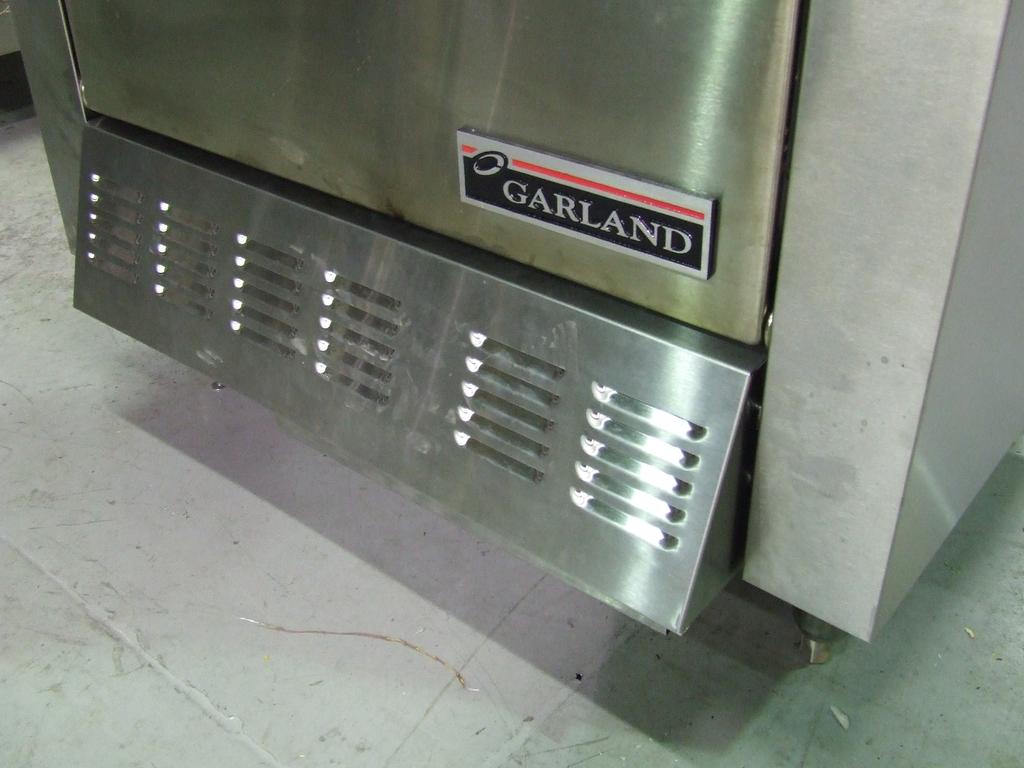
2 Instructions: 1) Remove Kick Plate Remove the two screws and washers at the hinge of the kick plate. This kick plate will not be reinstalled. Left: Unscrewing hinge screw of kick plate Right: Original kick plate. Will not be reinstalled. 2) Remove Front Air Shield The air shield is located directly above orifice. Remove by unscrewing two screws on the top of the shield Do not dispose. Will be reinstalled later. Left: Front Air Shield installed Right: Front Air Shield uninstalled 07/19/07 P/N Page 2
 Unscrew 11/16 compression nut on oven orifice fitting.")
 Unscrew 7/16 compression nut on Pilot Gas Outlet. 5) Unscrew 3/8 thermocouple nut. 6) Unscrew sheet metal screw holding bracket onto lower front frame.")
3 3) Uninstall Current Valve The following steps will apply if either an Invensys TS-11J Safety Valve or a Baso Valve are installed originally. See the below pictures for reference. 1) Unscrew 11/16 compression nut on oven orifice fitting. 2) Unscrew 11/16 compression nut on 11/16 elbow on Main Burner Gas Inlet. 3) Unscrew 7/16 compression nut on Pilot Gas Inlet. 4) Unscrew 7/16 compression nut on Pilot Gas Outlet. 5) Unscrew 3/8 thermocouple nut. 6) Unscrew sheet metal screw holding bracket onto lower front frame. 7) Remove valve TS-11 Safety Valve: Prior to removal Baso Safety Valve: Prior to removal 07/19/07 P/N Page 3


4 4) Remove Burner If the unit has an aeration plate, the burner is attached to aeration plate with one screw near the back of the oven. If the unit does not have an aeration plate, the burner is attached the oven bottom with one screw near the back of the oven Units with aeration plates and units without aeration plates will have different burners as shown in the following pictures. Both will not be reinstalled. A replacement burner with a welded side bracket is provided in the kit. Left: Burner installed with aeration plate Right: Burner uninstalled, aeration plate models. Flat bracket at end. Left: Burner installed with no aeration plate Right: Burner uninstalled, no aeration plate models. Tall bracket at end 07/19/07 P/N Page 4


5 5) Remove Aeration Plate (if present) If the pilot is installed on the left side of the burner in a horizontal position, unscrew the bracket connecting the pilot bracket to the aeration plate. The plate is attached to the oven with two screws directly underneath the oven burner orifice and another screw at the back end of the aeration plate. Left: Removal of 2 screws underneath orifice Right: Removed aeration plate with accompanying screws 6) Remove Original Pilot Assembly If pilot is installed on left side everything should now be detached and the entire assembly can simply be pulled out If pilot is installed on the right side, unscrew the pilot bracket from the oven bottom and remove the assembly. 07/19/07 P/N Page 5


6 7) Assemble New Pilot Assembly A colored line on the top of the pilot indicates the type of fuel used. A BLACK line is used on a natural gas pilot, whereas a RED line is used on a propane pilot. Both pilots are included in this kit. Ensure that the correct pilot is used for the unit. Unscrew the nut on the end of the selected pilot to release the nut, the ferrule and the orifice. Install the nut and the ferrule on one end of the flex tube. Place the orifice back into the pilot and screw on the flex tube. Push the thermocouple all the way into its slot on the pilot. Finished Pilot Assembly Left: Correctly assembled pilot with thermocouple pushed all the way through; thermocouple taller than hood, no excess length sticking out from bottom Right: Incorrect assembly, pilot not pushed all the way through; thermocouple shorter or equal in height to hood, excess length sticking out from bottom 07/19/07 P/N Page 6
. Bend the flex tube and thermocouple approximately as shown below.")

7 8) Attach Pilot Assembly to Welded Bracket on Burner Screw the pilot assembly to the welded bracket on the burner (Part 15, Assembly Drawing) using the included self-tapping screw (Part 16, Assembly Drawing). Bend the flex tube and thermocouple approximately as shown below. The pilot assembly fits onto the welded bracket via two holes, similar to original pilot bracket 9) Install Burner and Pilot Assembly Insert burner into orifice. Do not screw down the burner to the oven floor yet. Route thermocouple through the main gas / pilot gas tube opening in air shield. Route the pilot gas flex tube through the front area. Screw burner down to the hole at the far end of the oven (Part 9, Assembly Drawing). Routing of pilot gas flex tube through front area, thermocouple through hole in shield. 07/19/07 P/N Page 7


8 10) Reinstall Front Air Shield, Hearth The shield should not clamp down on any of the tubing. The flex tubing can be bent out of the way through the central opening in the shield. New welded bracket burner installed. 11) Pull Out Flex Tube and Thermocouple Ensure that the thermocouple is routed through the hole in the front shield made for the main gas inlet to the valve. This will make the thermocouple easier to install. Unbend and pull the pilot gas flex tube outwards as far as possible. Do not pull too hard as the pilot bracket on the burner may be damaged. Thermocouple and Pilot gas flex tube pulled out 07/19/07 P/N Page 8

 Unscrew one end of the 3/16 fitting (Part 4, Assembly Drawing) to release the nut and ferrule.")
 Ensure all connections are leak-proof. Do not over-tighten. Left: Measure 2.")
9 12) Install Extension Fitting (if applicable) If pilot gas tube going into the valve already has an extension piece (short piece of tubing plus 3/16 brass fitting), unscrew the shorter piece of tubing and proceed to Step 13. Otherwise, follow these steps to install the proper fitting. This step must be performed if a TS-11 valve was just removed. If a Baso valve was uninstalled, cut off 2.5 of the free end of the incoming pilot gas tube to remove the original ferrule and nut and a section of the tubing. If a TS-11 valve was uninstalled, cut off just enough tubing to remove the ferrule. Refer to the Assembly Drawing included in this manual: i) Unscrew one end of the 3/16 fitting (Part 4, Assembly Drawing) to release the nut and ferrule. Slide the nut and the ferrule onto the free end of the incoming pilot gas tube. ii) Insert the remaining portion of the fitting onto the end of the pilot gas tube. Screw on the nut to firmly attach the fitting to the tube. See pictures below for details. iii) Ensure all connections are leak-proof. Do not over-tighten. Left: Measure 2.5 from tip of pilot tube and cut Right: Pilot tube after cutting Screw this nut onto the fitting to secure the fitting onto the tube 3/16 Ferrule Extension fitting installed, with nut released to show location of ferrule 07/19/07 P/N Page 9

10 13) Attach Main Burner Gas Line Flex Tubes onto Valve Two brass fittings (Part 7, Assembly Drawing) should already be installed on the Main Burner gas inlet and outlet on the Baso valve. Unscrew the free end of each fitting to release the nut and ferrule. Install these on one end of each 7/16 flex tube (Part 2, Assembly Drawing) and attach the tubes to the Main Burner gas inlet and outlet on the Baso valve. See picture below for details. Nut and ferrule unscrewed from fitting on valve, installed on one free end of each 7/16 flex tube 07/19/07 P/N Page 10

11 14) Screw on Pilot Gas Flex Tube, Adjust Main Burner Gas Fitting Remove the brass nut and ferrule originally on the pilot gas outlet on the Baso valve (Part 5 and Part 6, Assembly Drawing). Install them onto the free end of the flex tube. Screw the pilot gas flex tube onto the Baso valve pilot gas outlet. This step should be done first to minimize stress on the flex tube during later steps. The fitting on the Main Burner Gas Inlet needs to be turned 180 from its original position, with the opening facing the right side of the oven. Loosen the nut, twist the fitting, and ensure that the nut is tightened properly once it is facing the right direction. Main Burner gas fitting turned 180, facing right side of oven Pilot Gas Flex Tube attached; Gas fitting turned around 07/19/07 P/N Page 11


12 15) Install New Pilot Gas Tube If a new 3/16 fitting (Part 4, Assembly Drawing) was installed on the pilot gas tube (Part 3, Assembly Drawing), unscrew the nut on the free end of the fitting to release the nut and the ferrule. If a fitting was already installed on the pilot gas tube, unscrew one end of the unused 3/16 fitting to release the nut and ferrule Unscrew the nut on the Baso valve pilot gas inlet to release the brass nut and the ferrule. Install these nuts and ferrules onto the new pilot gas tube as shown in the picture below. 3/16 Fitting Ferrule 3/16 Fitting Nut Baso Valve Ferrule Baso Valve Nut New Pilot Gas Tube Assembly: Nuts and Ferrules Install the pilot gas tube as shown below. Connect to the valve first for easier installation. New Pilot Gas Tube Installed 07/19/07 P/N Page 12
 and 7/16 ferrule (Part 11, Assembly Drawing). Connect the 7/16 flex tube and the thermocouple. Tighten all connections.")
 Attach Lighting Instructions to Valve Bracket The pilot lighting instructions are riveted on through the two holes in the")
13 16) Connect Remaining Tubes and Thermocouple The free end of each 7/16 flex tube from the valve should be fitted with a 7/16 nut (Part 10, Assembly Drawing) and 7/16 ferrule (Part 11, Assembly Drawing). Connect the 7/16 flex tube and the thermocouple. Tighten all connections. The final tube connections should be comparable to the picture below. Final Tube Configuration 17) Attach Lighting Instructions to Valve Bracket The pilot lighting instructions are riveted on through the two holes in the bracket. Ensure that the instructions are mounted in the correct direction shown below. 07/19/07 P/N Page 13
 underneath the valve assembly such that the taller face is flush up against the lower oven frame.")

14 18) Attach Bracket to Oven Unscrew the two screws holding the orifice bracket to the lower oven frame. Slip the bracket (Part 8, Assembly Drawing) underneath the valve assembly such that the taller face is flush up against the lower oven frame. Position the screw holes on the bracket such that two of them line up with the holes used for the orifice bracket. The third hole on the far right of the bracket will line up with a hole on the lower oven frame. Screw bracket onto oven frame with sheet metal screws (Part 9, Assembly Drawing). Left: Unscrewing two lower screws of orifice bracket Right: Attached valve bracket with arrows indicating location of screws 07/19/07 P/N Page 14
. Insert the bolt into the hole through the valve and align it with the small hole on the back of the bracket.")

15 19) Attach Valve Onto Bracket The valve is attached to the bracket using the bolt and nut provided (Part 13 and Part 12, Assembly Drawing). Insert the bolt into the hole through the valve and align it with the small hole on the back of the bracket. The large hole on the front may be used to insert the bolt into position. Screw the nut onto the protruding end of the bolt behind the bracket. Attaching bolt inserted through hole in valve indicated by arrow Nut holding bold in place on back of bracket 07/19/07 P/N Page 15


16 20) Install New Kick Plate The new kick plate (Part 14, Assembly Drawing) slants outwards to accommodate the valve. Ensure that the correct kick panel is installed. Left: Old kick plate with flat profile. Do not install this kick plate. Right: New kick plate with slanted profile. The new kick plate is designed to hook onto existing screws on the oven frame. Look for the original hooking screws used for the original kick plate. Original hooking screw on oven frame. Look for a similar screw on the other side of the oven Hook the kick plate onto the screws using the L-shaped indentations on the sides of the kick plates. Ensure that the plate does not rest against the bracket directly. 07/19/07 P/N Page 16

17 Installation Complete Installation Complete Kick Plate Off Installation Complete Kick Plate On 07/19/07 P/N Page 17
PS PERFORMER SERIES Effective March 2003
 PS PERFORMER SERIES Effective March 2003 Toll Free Phone, (US & Canada): (800) 427-6668 Toll Free Fax, (US & Canada): (800) 36-7745 http://www.garland-group.com FORM # PS Performer (Rev 7) Model Number
27" Natural Gas Conversion Manual
 S o n o m a PLATINUM EDITION 27" Natural Gas Conversion Manual FOR OUTDOOR USE ONLY TM 1 2 3 4 8 7 5 9 6 Part No. Qty Description 1 44213827 1 Hose 27" - 3/8" Flare Both Ends for Side Burner (NG) 2 40275101
B- and C- Series Ranges
 INSTALLATION INSTRUCTIONS for An AUTOMATIC OVEN PILOT LIGHT & GAS VALVE SHUTOFF SYSTEM for INCLUDING MODELS: B- and C- Series Ranges Models B & BZ Model 90-C Model 61-C Model 41-C Every effort to assure
SIT Pilot Assembly Retrofit - # 308 (Replaces R. Shaw Pilot Asbly) (SKU # )
 (SKU # )") Check Condition of Shipment SIT Assembly Retrofit - # 308 Upon receipt of this kit, check the condition of the packaging. Damage to the package should be noted on the carrier's freight receipt. Any damage
Check Condition of Shipment SIT Assembly Retrofit - # 308 Upon receipt of this kit, check the condition of the packaging. Damage to the package should be noted on the carrier's freight receipt. Any damage
NATURAL GAS CONVERSION MANUAL For Model FSISLP
 NATURAL GAS CONVERSION MANUAL For Model FSISLP FOR OUTDOOR USE ONLY 1 4 3 6 5 2 Part No. Qty Description 1 RCOZZ00341A 1 Main Burner Valve & Manifold Assembly with Valves (NG) 2 RPAZZ00002A 1 Thread Sealing
IR 2000 Series Medium Duty Range w/standard Oven ITEM NO DESCRIPTION PART # 24" 36" 48" 60" 72" Griddle Plate Assembly 24"
 1 Griddle Plate Assembly 12" 20006 1 1 1 1 1 Griddle Plate Assembly 24" 20007 1 1 1 1 1 Griddle Plate Assembly 36" 20008 1 1 1 1 Griddle Plate Assembly 48" 20009 1 1 1 Griddle Plate Assembly 60" 20010
IAG Air / Oil Separator (AOS) For STi
 For STi") IAG Air / Oil Separator (AOS) For 2008-14 STi Part# IAG-ENG-7000 Tools Required: Ratchet, torque wrench, extensions, needle nose pliers, hose cutter, snips/scissors Sockets: 10mm, 12mm 13mm Wrenches: 10mm,
IAG Air / Oil Separator (AOS) For 2008-14 STi Part# IAG-ENG-7000 Tools Required: Ratchet, torque wrench, extensions, needle nose pliers, hose cutter, snips/scissors Sockets: 10mm, 12mm 13mm Wrenches: 10mm,
36/60/160/260 L Series Gas Ranges
 VULCAN L Series Gas Ranges 36/60/160/260 L Series Gas Ranges 34 THRU 41 1 5 51 52 26 42 THRU 49 55-56-57 2-3-4 33 31-32 25 29-30 27 15 PL-53065 14 13 12 28 24 23 22 21 20 19 18 16 17 52 11 10 9 8 7 6 632
INSTALLATION INSTRUCTIONS FOR PCDE-36VA CONVERSION KIT
 INSTALLATION INSTRUCTIONS FOR PCDE-36VA CONVERSION KIT CONVERTING FROM NATURAL GAS TO PROPANE/LP GAS For Use When Converting Model (V)V36ENA Series This conversion kit must be installed by a qualified
Note: An arrow ( ) found in the text signifies change in content.
 found in the text signifies change in content.") Installation Instructions LPK-OH - LEGACY/PHOENIX NG to LP Gas Conversion Kit Models: LEGACY42-IFT PHOENIX42-IFT WARNING: This conversion kit shall be installed by a qualified service agency in accordance
Installation Instructions LPK-OH - LEGACY/PHOENIX NG to LP Gas Conversion Kit Models: LEGACY42-IFT PHOENIX42-IFT WARNING: This conversion kit shall be installed by a qualified service agency in accordance
Auxiliary Transmission Filter Kit
 19 July 2012 Dodge Transmission Filter Kit # 1064017-1 - Auxiliary Transmission Filter Kit Part # Vehicle Application 1064017 Dodge 1994-2007 The BD Transmission Filter Kit will provide added security
PARTS LIST. X Series Gas Restaurant Ranges X24 / X36 / X60. models. Parts & Service.
 X Series Gas Restaurant Ranges models X24 / X36 / X60 PARTS LIST Parts & Service P (USA & Canada): 1 800 427 6668 F (USA & Canada): 1 800 361 7745 www.garland-group.com Garland Commercial Ranges, Ltd.
Installation Instructions
 Installation Instructions For PTI STEZA C (2x2 Burner Configuration) & PTI STEZB C (3x1 Burner Configuration) Revision E Safe-T-Element Installation Instructions Table of Contents 1. PREPARATION..3 1.1
3 October 2016 PN# V Dodge Twin Turbo Kit (I-00274) ½ D o d g e 2 4 v I S B
 ½ D o d g e 2 4 v I S B") 3 October 2016 PN#1045320 24V Dodge Twin Turbo Kit (I-00274) 1 DOWNLOAD ENHANCED INSTALL MANUALS AT dieselperformance.com BD Twin Turbo Kit 1998½- 2 0 0 2 D o d g e 2 4 v I S B Part# 1045320 PLEASE READ
3 October 2016 PN#1045320 24V Dodge Twin Turbo Kit (I-00274) 1 DOWNLOAD ENHANCED INSTALL MANUALS AT dieselperformance.com BD Twin Turbo Kit 1998½- 2 0 0 2 D o d g e 2 4 v I S B Part# 1045320 PLEASE READ
Installing the CO 2 Cryogenic Oven Cooling Kit
 Installing the CO 2 Cryogenic Oven Cooling Kit Agilent 6850 Series II Network GC System Accessory G2625B This kit contains: Description Chassis 1 Chassis Cover 1 Ship kit: 1 Cooling coil 1 Coil bracket
INSTALLATION INSTRUCTIONS
 INSTALLATION INSTRUCTIONS 6525 REAR AXLE FLIP & HANGER KIT 5 OR 6 INCH LOWERING 14&UP CHEVROLET SILVERADO / GMC SIERRA 1500 Thank you for being selective enough to choose our high quality BELLTECH PRODUCT.
Safe-T-element Installation Instructions
 Safe-T-element Installation Instructions For: PTI STEZA (2x2 Burner Configuration) & PTI STEZB (3x1 Burner Configuration) Revision K (May. 3 2012) TABLE OF CONTENTS 1. PREPARATION... 3 1.1 General Safety
Installation Instructions for. For Use When Converting Model (V)M42(B) Vented Decorative Fireplace. Fold Bi-Fold Door After Releasing
M42(B) Vented Decorative Fireplace. Fold Bi-Fold Door After Releasing") Installation Instructions for PCBM-42 conversion kit Converting from Natural Gas to Propane/LP Gas For Use When Converting Model (V)M42(B) Vented Decorative Fireplace This conversion kit must be installed
Installation Instructions for PCBM-42 conversion kit Converting from Natural Gas to Propane/LP Gas For Use When Converting Model (V)M42(B) Vented Decorative Fireplace This conversion kit must be installed
Forge Motorsport BMW N54 Diverter Valves
 Forge Motorsport BMW N54 Diverter Valves Please thoroughly read through and familiarize yourself with these instructions in their entirety prior to beginning any part of the installation process of any
Installing the Flame Ionization Detector EPC Flow Control Manifold
 Installing the Flame Ionization Detector EPC Flow Control Manifold The FID EPC Flow Control Manifold kit can be used to replace any HP 6890 Series FID EPC flow control manifold. This kit contains: Kit
SD SERIES SD 448, SD 1048, SD 660, SD 1060, SD 866 AND SD , 6 AND 8 PIE PIZZA OVENS REPLACEMENT PARTS LIST
 SD SERIES SD, SD 0, SD 0, SD 00, SD AND SD 0, AND PIE PIZZA OVENS REPLACEMENT S LIST EFFECTIVE JULY 0, 0 Superseding All Previous Parts Lists. The Company reserves the right to make substitution in the
Griddle, Manual Viking Commercial Division 19
 , 60-30-12 2009 Viking Commercial Division 19 V60G- V30G- Part Number Part Description QTY QTY QTY 1 AV60PS Plate Shelf, Standard 60" 1 AV30PS Plate Shelf, Standard 30" 1 AV12PS Plate Shelf, Standard 12"
WPS-104 Heater. Installation Instructions
 WPS-104 Heater Installation Instructions For 2007 vehicles see page 15 WPS 104 HEATER SYSTEM INSTALLATION INSTRUCTIONS If this is a complete installation of top, windshield and heater system, for ease
PARTS LIST. U Series Infra-Red Salamander Broiler. models. Parts & Service.
 U Series Infra-Red Salamander Broiler models UIR36C UIR48 UIR36 UIR60 PARTS LIST Parts & Service T (USA & Canada): 1 800 47 6668 F (USA & Canada): 1 800 361 7745 www.garland-group.com Garland Commercial
AXEPZA PIZZA OVEN PARTS MANUAL SERIAL N FORWARD
 AlfrescoTM AXEPZA PIZZA OVEN PARTS MANUAL SERIAL N -00000 FORWARD LAST SAVED BY:»» Adrian ««Monday, October, 0 0:: AM 0 BIXBY DRIVE CITY OF INDUSTRY, CA. CREATED: 0/0/0 :0AM PART MANUALS PARTS MANUAL 00-000
INSTALLATION AND USER MANUAL
 INSTALLATION AND USER MANUAL SDKIT-730 & SDKIT-734 100% Bolt-On 150 PSI Train Horn System for 2011-2015 F-250 & F-350 Super Duty P/N SDKIT-730 P/N SDKIT-734 Thank you for purchasing a Kleinn Air Horns
Lingenfelter Signature Series Camaro SS Rear Valance
 Lingenfelter Signature Series 2010-2012 Camaro SS Rear Valance PN: L850161410 Lingenfelter Performance Engineering 1557 Winchester Road Decatur, IN 46733 (260) 724-2552 (260) 724-0422 fax www.lingenfelter.com
POLARIS XLT-SPECIAL TRIPLE PIPE SET P.N
 1998-99 POLARIS XLT-SPECIAL TRIPLE PIPE SET P.N. 09-596 Important: Read instructions carefully before installation. 1-Remove stock exhaust, Y-pipe, and rear muffler support. 2-Install three exhaust flanges,
Stock Pot Range. Gas & Electric Models. Parts List. GAS Models: ELECTRIC Models: G20-SP G20-SPH E20-SP E20-SPH. G20 shown
 Stock Pot Range Gas & Electric Models Parts List GAS Models: G20-SP G20-SPH ELECTRIC Models: E20-SP E20-SPH G20 shown Document Number: G_GMD_PL_STOCKPOTSTOVE_G20 (rev 4 updated: 07/6) Rating Plate Location
IHR Series With Standard Oven ITEM NO DESCRIPTION PART # 36" 1 Top Grate Cast Iron 12" X 28" - (Old Style) 1187 N/A *** 12" Top Grate 12 x 13 1/4
 1187 N/A *** 12 Top Grate 12 x 13 1/4") 1 Top Grate Cast Iron 12" X 28" - (Old Style) 1187 N/A *** 12" Top Grate 12 x 13 1/4 (Front) Open Burner 35334 3 *** 12" Top Grate 12 x 13 1/4 (Rear) Open Burner 35335 3 2 Top Grate Cast Iron 18" X 28"
1 Top Grate Cast Iron 12" X 28" - (Old Style) 1187 N/A *** 12" Top Grate 12 x 13 1/4 (Front) Open Burner 35334 3 *** 12" Top Grate 12 x 13 1/4 (Rear) Open Burner 35335 3 2 Top Grate Cast Iron 18" X 28"
IAG Street Series Air / Oil Separator (AOS) For 2017 WRX
 For 2017 WRX") P IAG Street Series Air / Oil Separator (AOS) For 2017 WRX Part# IAG-ENG-7152 Tools Required: Ratchet, torque wrench, extensions, needle nose pliers, hose cutter, snips/scissors, flathead screwdriver,
P IAG Street Series Air / Oil Separator (AOS) For 2017 WRX Part# IAG-ENG-7152 Tools Required: Ratchet, torque wrench, extensions, needle nose pliers, hose cutter, snips/scissors, flathead screwdriver,
Agilent G2738A Upstream Capillary Interface
 Agilent G2738A Upstream Capillary Interface 4890, 5890, and 6890 Gas Chromatographs Installation Guide Agilent Technologies Notices Agilent Technologies, Inc. 2003 No part of this manual may be reproduced
Toll Free Phone, (US & Canada): (800) Toll Free Fax, (US & Canada): (800)
: (800) Toll Free Fax, (US & Canada): (800)") H/P-280 SERIES RANGES Toll Free Phone, (US & Canada): (800) 427-6668 Toll Free Fax, (US & Canada): (800) 36-7745 http://www.garland-group.com Form # H/P-280 Series Parts (6/00) Page 2 Form # H/P-280 Series
H/P-280 SERIES RANGES Toll Free Phone, (US & Canada): (800) 427-6668 Toll Free Fax, (US & Canada): (800) 36-7745 http://www.garland-group.com Form # H/P-280 Series Parts (6/00) Page 2 Form # H/P-280 Series
IAG Competition Series Air / Oil Separator (AOS) For WRX
 For WRX") P IAG Competition Series Air / Oil Separator (AOS) For 2015-16 WRX Part# IAG-ENG-7252 Tools Required: Ratchet, torque wrench, extensions, needle nose pliers, hose cutter, snips/scissors, flat head screw
P IAG Competition Series Air / Oil Separator (AOS) For 2015-16 WRX Part# IAG-ENG-7252 Tools Required: Ratchet, torque wrench, extensions, needle nose pliers, hose cutter, snips/scissors, flat head screw
Pyro Deck Gas Deck Ovens
 Pyro Deck Gas Deck Ovens models GPD48, GPD60 Phone (US & Canada): 1 800 427 6668 Fax (US & Canada): 1 800 361 7745 www.garland-group.com G_GO_PL_PYRODECK_GPD4860 (Rev 9) Quality Factory Replacement Parts
SAFETY THIS PRODUCT IS FOR OFFROAD USE ONLY. ALL LIABILITY FOR INSTALLATION AND USE RESTS WITH THE OWNER.
 SAFETY Your safety and the safety of others is very important. In order to help you make informed decisions about safety, we have provided installation instructions and other information. These instructions
2015+ SUBARU STI FRONT-MOUNT INTERCOOLER PARTS LIST AND INSTALLATION GUIDE INSTALL DIFFICULTY DISCLAIMER CAUTION INSTALL PROCEDURE TOOLS NEEDED
 PARTS LIST AND PARTS INCLUDED 1PC ALUMINUM INTAKE PIPE 1PC BAR-AND-PLATE INTERCOOLER 1PC STEEL CRASH BAR W/ MOUNTING HARDWARE 2PC HOT-SIDE INTERCOOLER PIPES 2PC COLD-SIDE INTERCOOLER PIPES 1PC BPV FLANGE
GAS COUNTER EQUIPMENT PARTS / SERVICE MANUAL
 THERMA-TEK RANGE CORPORATION QUALITY AND STRENGTH GAS COUNTER EQUIPMENT PARTS / SERVICE MANUAL Models covered in this manual include: Open Top Hot Plates: TCHP12-1, TCHP12-2, TCHP24-2, TCHP24-4, TCHP36-6,
IAG Competition Series Air / Oil Separator (AOS) For 2017 STI
 For 2017 STI") P IAG Competition Series Air / Oil Separator (AOS) For 2017 STI Part# IAG-ENG-7251 Tools Required: Ratchet, torque wrench, extensions, needle nose pliers, hose cutter, snips/scissors, flat head screw driver,
P IAG Competition Series Air / Oil Separator (AOS) For 2017 STI Part# IAG-ENG-7251 Tools Required: Ratchet, torque wrench, extensions, needle nose pliers, hose cutter, snips/scissors, flat head screw driver,
GARLAND WENDY S COMBO RANGE STW286, STW28 SERIES
 GARLAND WENDY S COMBO RANGE STW286, STW28 SERIES Toll Free Phone, (US & Canada): (800) 427-6668 Toll Free Fax, (US & Canada): (800) 361-7745 http://www.garland-group.com Form # stwparts (2/2000) Page 2
COS-8G & COS-8GDS COMBI OVENS BCS-G STEAMER CNV-8G CONVECTION OVEN REPLACEMENT PARTS LIST
 COS-G & COS-GDS COMBI OVENS BCS-G STEAMER CNV-G CONVECTION OVEN REPLACEMENT PARTS LIST EFFECTIVE APRIL 0, 0 Superseding All Previous Parts Lists. The Company reserves the right to make substitution in
1080 CF Valve Replacement Instructions
 Overview This kit includes the newer American Flame gas control valve designed specifically for the 1080 CF gas fireplace. If you have a 1080 CF fireplace, and you are uncertain as to whether this kit
Artisan. AAEP-32 Parts Manual BUILT-IN 32 BBQ GRILL WITH THREE BURNERS
 AAEP- Parts Manual BUILT-IN BBQ GRILL WITH THREE BURNERS 00-0086 /-0 X /8 - TRUSS HEAD - PHILIPS SCREW 90-0 ARTISAN BBQ GRID - 9.8" WIDE 90-060 ART- WARMING GRID 90-0 SPRING TEMPERED-. OD x.87 L 90-06
MAINTENANCE ROAD 2013 WHEELS TECHNICAL MANUAL
 2013 WHEELS TECHNICAL MANUAL ROAD CYCLOCROSS PISTA GROUPSET TYPE OPERATION REVISION DESCRIPTION ROAD GROUPSETS CONE / CUP MOVEMENT 002 1/2011 SERVICING FRONT HUB ASSEMBLY PRODUCTS ON WHICH THE PROCEDURE
Performance Air Intake, 2015+
 PARTS LIST AND PARTS LIST 1PC ALUMINUM INTAKE PIPE 1PC HIGH-FLOW, OILED AIR FILTER 1PC SILICONE INDUCTION HOSE 1PC AIRBOX 1PC 1/16 RUBBER STRIPPING, 9 LENGTH 1PC 1/16 RUBBER STRIPPING, 8.5 LENGTH 1PC WORM-GEAR
Installing a PTV Inlet
 Agilent 6850 Series II Network GC System Accessories G3345B (Septumless) and G3346B (Septum) These instructions are divided into two parts: Part 1 to prepare the Electronic Pressure Control ("EPC") module
Stock Pot Range. models (Electric) E20-SP, E20-SPC (Gas) G20-SP, G20-SPH.
 E20-SP, E20-SPC (Gas) G20-SP, G20-SPH.") Stock Pot Range models (Electric) E20-SP, E20-SPC (Gas) G20-SP, G20-SPH Phone (US & Canada): 1 800 427 6668 Fax (US & Canada): 1 800 361 7745 www.garland-group.com G_GMD_PL_STOCKPOTSTOVE_G20 (Rev 3) Quality
Stock Pot Range models (Electric) E20-SP, E20-SPC (Gas) G20-SP, G20-SPH Phone (US & Canada): 1 800 427 6668 Fax (US & Canada): 1 800 361 7745 www.garland-group.com G_GMD_PL_STOCKPOTSTOVE_G20 (Rev 3) Quality
Artisan. AAEP-36 Parts Manual. BUILT-IN 36 BBQ GRILL WITH THREE BURNERS Serial Numbers up to
 AAEP-6 Parts Manual BUILT-IN 6 BBQ GRILL WITH THREE BURNERS Serial Numbers up to 7-99999 00-0086 /-0 X /8 - TRUSS HEAD - PHILIPS SCREW 90-0 ARTISAN BBQ GRID - 9.8" WIDE 90-0 ARTISAN BBQ GRID -.8" WIDE
BS-RX, BS-WX, BS-CX. Gas Infrared Salamander Broiler Model_BS-CX
 U_GMD_PL_BROILER_BSRWXBSWXBSCX_1.pdf 1 3003400 Main Top 1 2 3002400 Spring Bracket 1 3 3003700 Inner Top - BS-R 1 4 3002500 Back Flue Support 1 5 3006700 Wall Mount Support 2 6 3003801 Back and Bottom
2017+ L5P Duramax 3 ½ Down Pipe & EGR Fix Kit
 2017+ L5P Duramax 3 ½ Down Pipe & EGR Fix Kit Covers installation of PN s: WCF100630, WCF100829 Note: This Kit is for off road competition use only! Off Road Competition Use Tuning & Exhaust System is
SUNGLO REPLACEMENT HEATER HEADS PRICING
 Manufactured by Infrared Dynamics 888-Warm-Glo 30 Pamaron Way Suite L Novato CA 94949 SUNGLO REPLACEMENT HEATER HEADS PRICING Item # Description $ Price 10278 1 Natural Gas Head Assembly w/o Spark Ignition
GAS CONVERSION KIT INSTALLATION INSTRUCTIONS
 GAS CONVERSION KIT INSTALLATION INSTRUCTIONS These instructions apply to the following gas conversion kits: 8261139 8261140 8261141 8261142 8261143 8261144 8261158 8261747 8261748 8261964 8261965 8263059
INSTALLATION MANUAL BULLET PROOF OIL COOLER KIT F-SERIES
 INSTALLATION MANUAL BULLET PROOF OIL COOLER KIT 2003-2007 F-SERIES NEAL TECHNOLOGIES, INC. U.S. PATENT 8,375,917; 8,505,512 and OTHER PATENTS PENDING UPDATED 1/8/2018 2014 BULLET PROOF DIESEL BEFORE You
IAG Street Series Air / Oil Separator (AOS) For WRX
 For WRX") P IAG Street Series Air / Oil Separator (AOS) For 2015-16 WRX Part# IAG-ENG-7152 Tools Required: Ratchet, torque wrench, extensions, needle nose pliers, hose cutter, snips/scissors, flat head screw driver,
P IAG Street Series Air / Oil Separator (AOS) For 2015-16 WRX Part# IAG-ENG-7152 Tools Required: Ratchet, torque wrench, extensions, needle nose pliers, hose cutter, snips/scissors, flat head screw driver,
Catalog of Replacement Parts
 Catalog of Replacement Parts GAS RESTAURANT RANGES MODEL EG24L EG36L EG48L EG60L EG160L EG260L ML-52486 ML-52487 ML-114956 ML-52488 ML-52489 ML-52490 MODEL EG36L FOR SUPERIOR Superior Products Mfg. Co.
Olson Kustom Works th St SE #M, Monroe, WA (949)
") Olson Kustom Works 17404 147 th St SE #M, Monroe, WA 98272 (949)742-0613 Jesse@OKW-Inc.com FOR REVISIONS ALL 2017 BRACKET REVISIONS, revised July 2017 Thank you for your purchase from OKW. If you have
Olson Kustom Works 17404 147 th St SE #M, Monroe, WA 98272 (949)742-0613 Jesse@OKW-Inc.com FOR REVISIONS ALL 2017 BRACKET REVISIONS, revised July 2017 Thank you for your purchase from OKW. If you have
Firehawk Second Stage Regulator Fire Service
 Firehawk Second Stage Regulator Fire Service MAINTENANCE AND REPAIR TAL 1701 (L) Rev. 2 MSA 2017 Prnt. Spec. 10000005389(I) Mat. 10147454 Doc. 10147454 TAL 1701 (L) Rev. 2-10147454 2 NON-CBRN FIREHAWK
MODEL RVS304. REMOTE CONTROLLED SAFETY PILOT KIT Supplemental Installation Instructions for use with Natural Gas Log Sets
 MODEL RVS304 REMOTE CONTROLLED SAFETY PILOT KIT Supplemental Installation Instructions for use with Natural Gas Log Sets NOTE: This kit is for both Natural Gas and LP Gas applications. For LP (Propane)
SERVICE MANUAL RRG SERIES HEAVY DUTY GAS GRIDDLE - NOTICE - ML ML ML RRG Shown
 SERVICE MANUAL RRG SERIES HEAVY DUTY GAS GRIDDLE 24RRG 36RRG 48RRG 60RRG ML-135339-00024 ML-135340-00036 ML-135341-00048 ML-135342-00060 24RRG Shown - NOTICE - This Manual is prepared for the use of trained
Step 6: Remove and save the MAP sensor for later use. Step 7: Remove the passenger side intercooler pipe and the EGR intake manifold.
 LBZ Twin kit Install Step 1: Disconnect both batteries. Step 2: Drain coolant and oil also remove passenger side inner fender. Step 3: Remove intake box and piping. (Remove and save the MAF sensor in the
OIL COOLER KIT INSTALLATION INSTRUCTIONS PART NUMBER D
 OIL COOLER KIT INSTALLATION INSTRUCTIONS PART NUMBER D570-0904 APPLICATION: 2011-2012 E90 335i/xi (N55 engine) with BMW standard bumper and with stock oil cooler Congratulations for being selective enough
Installation Instructions
 2011-2013 LML DURAMAX COMPOUND-ADD 2011-2015 LML A Duramax TURBO KIT Add INSTALL A Turbo INSTRUCTIONS Compound Kit Installation Instructions 1-800-955-0476 - www.industrialinjection.com - info@industrialinjection.com
Installing a Cool On-Column Inlet
 Agilent 6850 Series II Network GC System Accessory G3344B This kit contains: Description Quantity Machine screws, M4 x 0.7 12 mm 6 Cable ties,.062.625 diameter 6 Ship kit* 1 T-20 Torx screw, M4 x 8 mm
Installing the Integral Platen Blow Off Valve
 Instruction Sheet Installing the Integral Platen Blow Off Valve WARNING: Allow only qualified personnel to perform the following tasks. Observe and follow the safety instructions in this document and all
ETP-5G & ETP-10G ECO-TECH PLUS GAS CONVECTION STEAMER PARTS AND SERVICE MANUAL
 ETP-5G & ETP-10G ECO-TECH PLUS GAS CONVECTION STEAMER PARTS AND SERVICE MANUAL EFFECTIVE JANUARY 10, 2018 Superseding All Previous Parts Lists. The Company reserves the right to make substitution in the
Wrenches: ⅞, 8mm, 10mm, 13mm, 19mm P. allen, Other: Electrical Tape
 IAG Street Series Air / Oil Separator (AOS) For 2008-14 STI Part# IAG-ENG-7100 Tools Required: Ratchet, torque wrench, extensions, needle nose pliers, hose cutter, snips/scissors, flat head screw driver,
Crawford Performance Top Mount Air/Oil Separator Version 2 (S0714-1)
") Crawford Performance Top Mount Air/Oil Separator 02-07 Version 2 (S0714-1) Parts List Part Number Quantity Description Sent Received S0707-1 1 TMIC Air/Oil Separator V2 F0365 1 Crank Case Breather Connector
Crawford Performance Top Mount Air/Oil Separator 02-07 Version 2 (S0714-1) Parts List Part Number Quantity Description Sent Received S0707-1 1 TMIC Air/Oil Separator V2 F0365 1 Crank Case Breather Connector
ASSEMBLY & INSTALLATION INSTRUCTIONS
 ASSEMBLY & INSTALLATION INSTRUCTIONS VEHICLE MOUNT KIT 99101087 AND VEHICLE CENTER MEMBER For 26 Series: 99100890 TO FIT 2009 & Later FORD F150 4x4 (without EcoBoost V6) 2011 & Later FORD F150 4x4 (with
4. Remove (4) 10mm and (1) 7mm bolt that holds fascia at front corners, on each side
 10mm and (1) 7mm bolt that holds fascia at front corners, on each side") 2010 Camaro LS3 1. Disconnect battery ground 2. Remove front wheels 3. Remove (5) push pins and (5) #20 torx screws on inner front wheel well liners and remove liners on each side 4. Remove (4) 10mm and
2010 Camaro LS3 1. Disconnect battery ground 2. Remove front wheels 3. Remove (5) push pins and (5) #20 torx screws on inner front wheel well liners and remove liners on each side 4. Remove (4) 10mm and
LI-ION BATTERY UPFIT KIT
 LI-ION BATTERY UPFIT KIT P/N 2881852 APPLICATION E2, E4, E6, and el XD BEFORE YOU BEGIN Read these instructions and check to be sure all parts and tools are accounted for. Please retain these installation
GF Sentry Series Infra-Red
 GF Sentry Series Infra-Red Salamander Broilers Parts List Models GFIR36C GFIR36 GFIR8 GFIR60 Document Number: G_GMD_PL_IRBROILER_GFIR (Rev 5 Updated 07/6) Rating Plate Location Remove the drip tray to
MF 9690, 9790, Challenger 660, 670
 Ag Leader Technology Parts List Note: Indented items indicate parts included in an assembly listed above Quantity by Model Part Name/Description Part No. MF 9690 MF 9790 Challenger 660 Challenger 670 Instruction
INSTALLATION INSTRUCTIONS
 INSTALLATION INSTRUCTIONS FUEL PUMP HANGER 08+ MITSUBISHI LANCER EVOLUTION X Support: info@radiumauto.com Document# 19-0116 WARNING: DO NOT EXPOSE WORK AREA TO ANY SPARKS OR FIRE. DO NOT SMOKE WHILE WORKING
TECHNICAL MANUAL WENDY'S RANGE MODEL: C0300HT AND C0301 HT
 southbend TECHNICAL MANUAL A MIDDLEBY COMPANY WENDY'S RANGE MODEL: C0300HT AND C0301 HT This manual is intended for the use of Southbend Authorized Service Agencies and their associates. Service work should
WENDY S COMBO RANGE STW286A SERIES
 WENDY S COMBO RANGE STW286A SERIES Manufactured From June 16, 2005 PA R TS LI IS T Toll Free Phone, (US & Canada): (800) 427-6668 Toll Free Fax, (US & Canada): (800) 361-7745 http://www.garland-group.com
APIKOL Ur-S4/S6 Gen. II Front Mount Intercooler INSTALLATION INSTRUCTIONS
 APIKOL Ur-S4/S6 Gen. II Front Mount Intercooler INSTALLATION INSTRUCTIONS Only work underneath your vehicle after properly supporting it with adequate jack stands on a flat surface. NEVER work under a
INSTALL MANUAL D o d g e 1 2 v 6 B T A PLEASE READ ALL INSTRUCTIONS BEFORE INSTALLATION.
 PN#1045310 12V Dodge Twin Turbo Kit (I-00273) 1 INSTALL MANUAL BD Twin Turbo Kit 1994-1 9 9 8 D o d g e 1 2 v 6 B T A Part# 1045310 PLEASE READ ALL INSTRUCTIONS BEFORE INSTALLATION. * Picture as shown
INSTALLATION INSTRUCTIONS PORT INJECTION KIT (PIK)
") INSTALLATION INSTRUCTIONS PORT INJECTION KIT (PIK) FORD FOCUS 2.3L ECOBOOST Document: 19-0155 Support: info@radiumauto.com IMPORTANT NOTES: 1. This installation requires minor metal cutting. Air tools
INSTALLATION INSTRUCTIONS PORT INJECTION KIT (PIK) FORD FOCUS 2.3L ECOBOOST Document: 19-0155 Support: info@radiumauto.com IMPORTANT NOTES: 1. This installation requires minor metal cutting. Air tools
TO BE USED ONLY BY AUTHORISED PERSONNEL
 SERVICE MANUAL for BOSTON (MG 3000 STD) SANTA FE (CALGARY, MG 3000 FLS) & ODESSA (PG 3000) GAS FIRES TO BE USED ONLY BY AUTHORISED PERSONNEL PART No 588402 Issue E Nov. 2001 CONTENTS TROUBLESHOOTING Page
Congratulations on purchasing the Edge Juice/Attitude system for the Dodge Cummins Diesel.
 Getting Started About the Juice Congratulations on purchasing the Edge Juice/Attitude system for the Dodge Cummins Diesel. The Juice/Attitude system features an intelligent module (Juice) that acts as
Thank you for purchasing the Craven Speed FlexPod Complete Gauge Pod Kit For R56, R58, R59, R60 with Refresh Engines (2011+)
") Thank you for purchasing the Craven Speed FlexPod Complete Gauge Pod Kit For R56, R58, R59, R60 with Refresh Engines (2011+) Before You Start Please read instructions completely before installing. These
Thank you for purchasing the Craven Speed FlexPod Complete Gauge Pod Kit For R56, R58, R59, R60 with Refresh Engines (2011+) Before You Start Please read instructions completely before installing. These
JBA Cat4ward Shorty Header Install (05-10 Mustang GT and Bullitt)
") JBA Cat4ward Shorty Header Install (05-10 Mustang GT and 08-09 Bullitt) Installation Time: 6-8 Hours (Depending on Tools and Help) Tools Required: 8mm Socket 10 mm Socket 13mm Socket 15mm Deep Socket Ratchet
JBA Cat4ward Shorty Header Install (05-10 Mustang GT and 08-09 Bullitt) Installation Time: 6-8 Hours (Depending on Tools and Help) Tools Required: 8mm Socket 10 mm Socket 13mm Socket 15mm Deep Socket Ratchet
INSTALLATION INSTRUCTIONS AOS-R (Air Oil Separator-Return) Turbo Subaru and STi Document# Support:
 Turbo Subaru and STi Document# Support:") INSTALLATION INSTRUCTIONS AOS-R (Air Oil Separator-Return) 02-14 Turbo Subaru and 2015+ STi Document# 19-0102 Support: info@radiumauto.com These instructions are based on a vehicle with an OEM turbocharger
INSTALLATION INSTRUCTIONS AOS-R (Air Oil Separator-Return) 02-14 Turbo Subaru and 2015+ STi Document# 19-0102 Support: info@radiumauto.com These instructions are based on a vehicle with an OEM turbocharger
Crawford Performance Top Mount Air/Oil Separator Install Instructions Version 1.12
 Crawford Performance Top Mount Air/Oil Separator Install Instructions Version 1.12 Parts List Part Number Quantity Description Sent Received S0774 1 TMIC Air/Oil Separator F0365 1 Crank Case Breather Connector
INSTALLATION INSTRUCTIONS
 INSTALLATION INSTRUCTIONS Accessory Application Publications No. SYSTEM 2005 ACCORD All 27511 (DX, LX) 2-AND 4-DOOR Issue Date AUG 2004 PARTS LIST Security System Attachment (LX): P/N 08E55-SDA-100A Unit
Procharger Stage II Intercooled Supercharger System (11-14 GT)
") Procharger Stage II Intercooled Supercharger System (11-14 GT) Installation Time: Approximately one day. Installed on 2012 Mustang GT 5.0/Manual Required Tools 3/8 Socket Set (Standard and Metric) 1/2
Procharger Stage II Intercooled Supercharger System (11-14 GT) Installation Time: Approximately one day. Installed on 2012 Mustang GT 5.0/Manual Required Tools 3/8 Socket Set (Standard and Metric) 1/2
<THESE INSTRUCTIONS MUST BE GIVEN TO THE END USER> B&W
 B&W Trailer Hitches 6 Hawaii Rd / PO Box 86 Humboldt, KS 66748 P:60.473664 F:60.869.903 Turnoverball Gooseneck Hitch Installation Instructions MODEL 08
Mazda 3 & Mazdaspeed 3 Oil Cooler Installation Instructions
 Page1 2007-2009 Mazda 3 & Mazdaspeed 3 Oil Cooler Installation Instructions Tooling: Jack and jack stands or a lift Socket wrench and torque wrench 10mm and 14mm sockets 3/16 Allen wrench 10mm wrench Pliers
COLD AIR INTAKE INSTALLATION INSTRUCTIONS PART NUMBER D A. APPLICATION: E36/7 M-Roadster or M-Coupe 3.
 COLD AIR INTAKE INSTALLATION INSTRUCTIONS PART NUMBER D760-0323A APPLICATION: 1998-00 E36/7 M-Roadster or M-Coupe 3.2 Liter PARTS LIST Air Filter Assembly 3 1/2" Tube Intake Shield Silicone Hose Airflow
INSTALLATION INSTRUCTIONS
 INSTALLATION INSTRUCTIONS COOLANT EXPANSION TANK FORD FOCUS Document: 19-0151 Support: info@radiumauto.com WARNINGS: DO NOT WORK ON THE COOLANT SYSTEM WHEN THE ENGINE IS AT OPERATING TEMPERATURE. WAIT
SALEEN SPEEDLAB BOOST AND WATER TEMPERATURE GAUGE POD KIT
 = SALEEN SPEEDLAB BOOST AND WATER TEMPERATURE GAUGE POD KIT INSTALLATION MANUAL: 2005-09 Mustang 4.6L 3V P/N: 10-8002-C12000B KIT P/N: 10-2903-B11511* Saleen Performance, Inc. 1225 East Maple Rd. Troy,
INSTALLATION INSTRUCTIONS AOS-R (Air Oil Separator-Return) Turbo Subaru and STi Document# Support:
 Turbo Subaru and STi Document# Support:") INSTALLATION INSTRUCTIONS AOS-R (Air Oil Separator-Return) 02-14 Turbo Subaru and 2015+ STi Document# 19-0102 Support: info@radiumauto.com These instructions are based on a vehicle with an OEM turbocharger
INSTALLATION INSTRUCTIONS AOS-R (Air Oil Separator-Return) 02-14 Turbo Subaru and 2015+ STi Document# 19-0102 Support: info@radiumauto.com These instructions are based on a vehicle with an OEM turbocharger
B21 Series BASOTROL Gas Valve
 Installation Instructions B21 Issue Date September 19, 2017 Installation IMPORTANT: These instructions are intended as a guide for qualified personnel installing or servicing BASO Gas Products. Carefully
Section 7 - Troubleshooting Guide
 Section 7 - Troubleshooting Guide Section 7 - Troubleshooting Guide IMPORTANT While this troubleshooting guide provides information to aid in troubleshooting problems with the range, it does not contain
Marathoner Gold and SilverStar. Electric Convection Ovens
 SOUTHBEND Marathoner Gold and SilverStar Electric Convection Ovens Electric Convection Ovens Door Parts 1 1177102 Handle, Coated, 15" 2 1164527 Bushing, Bronze, Lower Oilite (4 qty.) 3 1092000 Oilite Thrust
PARTS LIST. Pyro Deck GPD Series Gas Deck Ovens GPD-48 GPD-60. models. Parts & Service.
 Pyro Deck GPD Series Gas Deck Ovens models GPD-8 GPD-60 PARTS LIST Parts & Service T (USA & Canada): 800 27 6668 F (USA & Canada): 800 36 775 www.garland-group.com Garland Commercial Ranges, Ltd. 77 Kamato
Installing a PTV Inlet
 Agilent 6850 Series II Network GC System Accessories G3345B (Septumless) and G3346B (Septum) There are kits for installing both septum and septumless PTV inlets. This document describes both installations.
M-9603-FST FOCUS ST COLD AIR INTAKE KIT INSTALLATION INSTRUCTIONS
 M-9603-FST Please visit www.fordracingparts.com for the most current instruction information.!!! PLEASE READ ALL OF THE FOLLOWING INSTRUCTIONS CAREFULLY PRIOR TO INSTALLATION. AT ANY TIME YOU DO NOT UNDERSTAND
The Combustex Pilot Pro 500 Ignition System with Pilot Tip and Flame Sensor
 OPERATIONS MANUAL The Combustex Pilot Pro 500 Ignition System with Pilot Tip and Flame Sensor The CSA approved alternative ignition system delivering safety, reliability and versatility. KEY FEATURES Unique
Subaru Front Mount Intercooler Kit STI Subaru Front Mount Intercooler Kit STI
 Subaru Front Mount Intercooler Kit STI 2008-2014 715500 Subaru Front Mount Intercooler Kit STI 2008-2014 Congratulations on your purchase of the Subaru Front Mount Intercooler Kit STI 2008-2014. The following