(12) Patent Application Publication (10) Pub. No.: US 2016/ A1
|
|
|
- Elfrieda Griffith
- 5 years ago
- Views:
Transcription
1 (19) United States (12) Patent Application Publication (10) Pub. No.: Hirschel et al. US O8541A1 (43) Pub. Date: Jan. 14, 2016 (54) SUBSTANCE DISPENSING DEVICE WITH SIGNALING DEVICE (71) Applicant: TecPharma Licensing AG, Burgdorf (CH) (72) Inventors: Jirg Hirschel, Bern (CH); Markus Tschirren, Burgdorf (CH) (21) Appl. No.: 14/858,755 (22) Filed: Sep. 18, 2015 Related U.S. Application Data (63) Continuation of application No. PCT/CH2014/ , filed on Mar. 20, (30) Foreign Application Priority Data Mar. 22, 2013 (EP) Publication Classification (51) Int. Cl. A6M5/20 ( ) A6M5/35 ( ) (52) U.S. Cl. CPC... A61M 5/2033 ( ); A61M 5/3157 ( ); A61M 2005/2013 ( ); A61M 2005/3109 ( ) (57) ABSTRACT Device for dispensing a Substance having: a dispensing ele ment through which the Substance can be dispensed, a dis placeable protective element for the dispensing element, a drive element that is coupled with the protective element and a feedback element which can generate a signal when or after a predefined quantity or the entire quantity of the Substance to be dispensed has been dispensed characterized in that the feedback device is coupled with the drive element.
2 yy.yyyyèno.????zzzzzzzzzzzzzzzzzzz?????????????zzzzzzzzzzzzzzzzzzzzzzz?zzzzzzzzzzzzzzzzzz> ì]]\ Jan. 14, 2016 Sheet 1 of I!
3 Jan. 14, 2016 Sheet 2 of 23
4
5 Jan. 14, 2016 Sheet 4 of 23 Ø ZZZZZZZZZZZZZZZZ7 2 8 Gjy 'fil
6 Jan. 14, 2016 Sheet 5 of 23 m.
7
8 Jan. 14, 2016 Sheet 7 of 23
9 TTG\ pri\\ Jan. 14, 2016 Sheet 8 of 23 iiiiiiiiiiiiiiiiiiiiiiiiiiiiiiiiiiiiiiiiiiiiiiiiiiiiii Efffffhritt?itiiiiiiiiiiiiiiiiiiiiiii??NI) **** ZZZZZZZZZZZZ
10 Jan. 14, 2016 Sheet 9 of 23
11 Jan. 14, 2016 Sheet 10 of 23 EZZZZ [[ÉŠ?ÉZZZZZZZZZZZZZZZZZZZZZZZZZZZZZZZZZZZ??
12 Jan. 14, 2016 Sheet 11 of 23 EL p II
13 Jan. 14, 2016 Sheet 12 of 23

14 Jan. 14, 2016 Sheet 13 of 23
15 L?zczaez::No.zzzzzzzzzzzzzzzzz?º????i?????-??i?????izzž????izzzzzzzzzzzzzzzzzzzzzz????zzzzzzzzzzzzZZZZZZZZZZZZZZZZ Jan. 14, 2016 Sheet 14 of 23 at:2:2:2:2:2,222zzzzzzzzzzzzzzzzzzzzzzzzzzzzzzzzzzzzzzzzzzzzzzzzzzzzz.zzzz!zzzzzzzzzzzzzzzzzzzzzzzzzzzzzzzzz
16 Jan. 14, 2016 Sheet 15 of 23?ffffffff?áZZZZZZZZZZZZZZZZZZZZZZZZZZZZZZZZZZZzzzzzzZzzzZZZZZZZZZZZZZZZZZZZZZZZZZZZZZZZZZZZZZZZzZ
17 Jan. 14, 2016 Sheet 16 of 23 }ZZZZZZZZZZZZZZZZZZZZZZZZZZZZZZZZZZZZ {
18 Jan. 14, 2016 Sheet 17 of 23 ZZZZZZZZZZZZZZZZZZZZZZzzzzzzzzzzzzzzzzzzzzzzzzZzZZZZZZZZZZZZZZ ~
19 Jan. 14, 2016 Sheet 18 of 23
20 Jan. 14, 2016 Sheet 19 of 23
21 Jan. 14, 2016 Sheet 20 of 23 :
22 Jan. 14, 2016 Sheet 21 of 23 g SI 61
23 Jan. 14, 2016 Sheet 22 of 23
24 Jan. 14, 2016 Sheet 23 of 23

25 Jan. 14, 2016 SUBSTANCE DISPENSING DEVICE WITH SIGNALING DEVICE CROSS-REFERENCE TO RELATED APPLICATIONS This application is a Continuation of International Patent Application No. PCT/CH2014/ filed Mar. 20, 2014, which claims priority to European Patent Application No filed Mar. 22, 2013, the entire contents of each are incorporated herein by reference. TECHNICAL FIELD 0002 The invention concerns a substance dispensing device, in particular, an injection device or an autoinjector, which features a signaling device to indicate, for example, optically, acoustically, and/or tactilely, when a Substance has been released or a dispensing has taken place, completely or at least, to a predefined extent. A Substance which can, for example, be dispensed automatically can be a fluid productor a medication, which may, for example, be liquid, paste-like or gel-like. BACKGROUND From WO 2011/123024A1, a medication dispens ing device with a drive device acting on a medication con tainer so as to hold the drive device in a pretensioned State is known. An activation device interacts, with the holding device, to release the drive device from the pretensioned state. A feedback device can interact both with the holding device and with the drive device in order to generate a signal, which indicates that the medication has been completely ejected WO94/11041 discloses an autoinjector with a first unit, which brings about an automatic needle penetration and which controls a second unit, which produces the release of the medication, so that the release of the medication is begun only if the needle penetration was carried out completely WO 2013/016832A1 discloses an injection device for the automatic dispensing with a needle protective device, which can be displaced from a distal to a proximal position and from there, to a needle protective position and with a drive device that can move in a housing, which is driven to a dispensing position with a drive means, and with a rotating sleeve, which can be rotated from a first to a second position and has a first profile, which is in an operative connection with a second profile of the drive device. The drive device rotates through the first profile and the second profile, the rotating sleeve from the first to the second position. SUMMARY One object of the invention is to make available a Substance dispensing device or an injection device, in which the user triggers an injection in a simple manner and can be informed by the device as to the correct functional course This object is attained by the device and method according to the independent claims, with advantageous fur ther developments defined in the dependent claims A device in accordance with the invention for administering a Substance is preferably an autoinjection device, which has an energy storage or a drive element, with which dispensing can be automatically carried out. Prefer ably, force or energy which is Supplied or applied externally, for example, by a user, is not required. The energy storage or drive element advantageously stores the complete energy required for an automatic release of the Substance. Such an energy storage or drive element can, for example, be a spring. This spring may be incorporated, into the injection device in an energy-storing state that is, for example, compressed, pulled apart, or also twisted and can release energy by an energy releasing process that is, for example, by relaxation if the spring was incorporated compressed or twisted, or undertorsional stress, or also by contraction if the spring was incorporated when pulled apart. The energy release advanta geously takes place directly or indirectly that is, via inter mediate components on a piston rod or pressure element which presses a stopper of a Syringe and can push this stopper into the Syringe Optionally, the energy storage element or another separate energy storage element can be provided, in order to automate the process of inserting a needle. The insertion process, however, can also be done manually it can, for example, be undertaken by a user-without usingenergy stored in the injection device for that purpose The administration device has a release element, for example, a needle, by means of which the Substance can be released. The needle is coupled with the container for the Substance to be released in a known manner, so that, for example, upon displacing the aforementioned stopper, the Substance passes through the needle and is released and injected at the distal front end of the substance A protective element is provided for the release element, for example, a sleeve which is to be pushed beyond the release element, which, for example, may be pushed axi ally, parallel to the longitudinal direction of a needle that serves as the release element. The protective element can Surround the release element, for example, radially, prior to the release, and also protrude beyond the release element in distal direction, so that the release element is essentially or completely surrounded or covered by the protective element. The protective element thereby advantageously has a passage opening for the release element, through which the release element can leave the protective area of the protective ele ment. The release element can be moved actively through the protective element and also the protective element can be removed actively from the release element that is, for example, pushed back in a proximal direction so as to release at least the distal area of the release element The protective element is coupled with a drive ele ment which is or may be designed separately from the afore mentioned, optionally provided drive elements or is designed, for example, as a second or third drive spring within an injection device. The protective element can be driven by this drive element. For example, the drive element can cause the protective element to be brought or pushed, over the release element once again after the Substance has been released. Optionally, the drive element can also serve as a holding element, for example, in order to hold the protective element, in a protective position, over or around the release element before and/or after a substance release. The drive element can be incorporated, in a relaxed state or in a tensioned or loaded that is, energy-containing or storing, state in the injection device, wherein this energy can be used to drive the protective element. If the drive element is incorporated in the injection device in a state in which it does not store energy, or stores a small amount of energy, then during a functional course before driving the protective element, the drive ele ment must be provided with energy by another element that

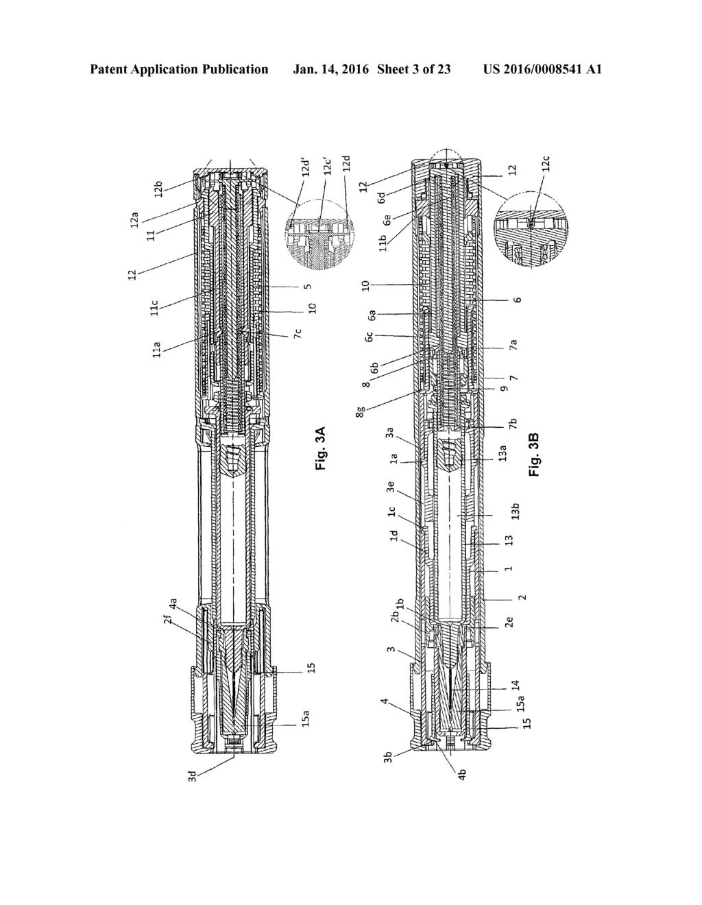
26 Jan. 14, 2016 is, for example, by a user or one of the aforementioned other drive elements, for example, a tensioned dispensing spring A feedback device of the injection device can gen erate a signal if a predefined quantity or the entire quantity of the Substance to be dispensed was released. The signal that is generated can be an acoustic signal that is, for example, a "click sound, which is generated if a moving element strikes another element. It is also possible for the acoustic signal to be, for example, a mechanically generated friction or scratch ing Sound, when two elements are moved relative to one another. The signal can also be a tactile or haptic signal that is, a signal which can be felt by a user. Such a signal can, for example, also be created by a stop of one element on another element, or a vibration or friction signal when two elements move, relative to one another. Furthermore, the signal can be a visual signal. Such as a color signal or a color area of the feedback device, which is displaced, for example, in a certain area. For example, the feedback device can carry a signaling color, which is moved out of a visible area, or is moved into a visible area, in order to indicate that a substance release has not yet taken place, or also that it has been concluded According to the invention, the feedback device is coupled with the drive element with which the protective element is also coupled. For example, the feedback device is a stop element that is, a pin or a sleeve which is acceler ated by a needle protective sleeve spring or is moved against a stop, wherein the needle protective sleeve spring acts on a needle protective element with pressure or exerts force on it, in order to bring or to hold in a protective position the needle protective element relative to the release element or to the needle The feedback element can, for example, strike the housing of the injection device and therefore move relative to it, wherein it is also possible that the feedback strikes any other part. Preferably, the feedback element is accelerated by the aforementioned drive element over a predefined distance, for example, Straight or in a rotational movement, in order to produce a strike, at a certain speed, and thus a noticeable feedback signal The device according to the invention can have another separate, second feedback device, which, for example, signals the beginning of the Substance release. It is conceivable that both feedback devices can also be imple mented in one element As already mentioned, the administration device can also have a second, third, fourth, or other drive element or energy storage element, which, for example, makes energy available to bring about the Substance release and/or energy for the carrying out of a needle penetration. This second or additional drive element is provided separately from the drive element which is coupled with the feedback device and can, for example, be functionally, completely separate from the feedback drive element. It is also possible that such an addi tional drive element releases or transfers energy to the feed back-drive element A modulation or dampening element can also be provided on the feedback element, by means of which the feedback coupling that is, for example, a feedback Sound or a tactile feedback signal can be influenced or modified. For example, straps or stop surfaces or dampening means may be provided, which delay or decelerate an impact or strike of the feedback device on a surface oran impact part. Likewise, it is possible for a modulation element to increase the Strike Sur face, in order to increase the signal strength that is to be generated. (0019. The feedback element can preferably be held by a releasable holding device until the end of the substance release, so that, for example, the feedback element is trig gered or released and, for example, is driven by a drive ele ment only if the Substance release is complete or has been carried out to a specific, previously defined extent that is, for example, the piston rod was pushed to a stipulated dis pensing point As mentioned above, the feedback coupling device can be a stop element which, for example, is accelerated or driven along a straight path, in order to strike, at the end, at a stopping place, and thus, create a feedback signal. It is also possible for the feedback device to be, for example, a rotating element, which, for example, carries out a rotational move ment after the stipulated ending of the complete Substance release and creates a rotational strike. For this, for example, torsional moment of a used spring that is, for example, a used needle protective spring or also an injection spring can be used In accordance with another aspect, the invention refers to a method for the release of a substance from a device that is described above, wherein the substance is automati cally released by means of a first drive element and a feedback signal for the signaling of the, for example, ended Substance release by means of a feedback element, driven by a separate, second drive element, is generated. The drive elements are consequently separate devices or functional units that is, for example, two separately provided springs which can, how ever, be coupled with one another, in order to transfer energy from a spring such as, from a drive spring to another spring that is, for example, the feedback spring This transfer of energy or force can take place before, during, or after the Substance release. BRIEF DESCRIPTION OF THE DRAWINGS 0023 FIG. 1 is a cross-sectional view along alongitudinal axis of a first embodiment of an injection device for the illustration of the concept FIG. 2 is an exploded view of the injection device shown in FIG FIGS. 3A and 3B are cross-sectional views of the injection device shown in FIG. 1, in the delivery state, rotated relative to one another by FIGS. 3C to 3G is the execution of the radial inside of the locking sleeve (180 execution) for the illustration of the relative movement of the engaging cams of the mecha nism holder and the click pin FIGS. 4A and 4B are cross-sectional views of the injection device shown in FIG. 1 in the inserted state, rotated by 90, if the injection device is or was pressed onto the injection site. (0028 FIGS. 4D to 4H are detailed views of the locking sleeve and the principle of the needle protective locking for the illustration of the relative movement of the intervening cams of the mechanism holder and the click pin FIGS. 5A and 5B are cross-sectional views of the injection device shown in FIG. 1, rotated relative to one another by 90, before the beginning of the dispensing FIGS. 6A and 6B are cross-sectional views of the injection device shown in FIG. 1, rotated, relative to one another, by 90 after the dispensing has been completed.

27 Jan. 14, FIGS. 7A and 7B are cross-sectional views of the injection device shown in FIG. 1, rotated, relative to one another, by 90 after the dispensing has been completed and the strike of a click element, confirming this completed dis pensing FIG. 8 is an exploded view of a second embodiment of an injection device FIGS. 9A and 9B are cross-sectional views of the injection device shown in FIG. 2 in the delivery state, rotated, relative to one another, by FIGS. 10A and 10B are longitudinal cross-sectional views of the injection device shown in FIG. 2 in the inserted state, rotated, relative to one another, by 90, if the injection device was pressed onto the injection site FIGS. 11A and 11B are cross-sectional views of the injection device shown in FIG. 2, rotated, relative to one another, by 90, after the dispensing has been completed and the signaling of the end of the injection by the strike of the release sleeve on the end cap has taken place FIGS. 12A and 12B are cross-sectional views, rotated, relative to one another, by 90, with regard to a third embodiment of an injection device in the delivery state FIGS. 13A and 13B are cross-sectional views of the injection device shown in FIGS. 12A and 12B, rotated, rela tive to one another, by 90, with regard to the injection device after a completed penetration and dispensing movement and confirmation of the complete dispensing by Striking the release sleeve on the bottom of the mechanism holder FIG. 14A shows a fourth embodiment of an injec tion device in the delivery state, in which the Syringe spring makes available the energy for the end click (end-of-injection click) FIG. 14B shows the injection device, in accordance with FIG. 14A, in the dispensed state before the end click FIG.15A shows an embodiment of a functional unit of an end-click unit of an injection device in the delivery state, in which a rotational Strike is generated by a torsional moment of the injection spring FIG. 15B shows the functional unit of FIG. 15A with a generated end click FIG.16A shows an embodiment of a functional unit of an injection device in the delivery state for the generation of an end click by the energy of the needle protective sleeve Spring FIG. 16B shows the functional unit of FIG. 16A after the generated end click. DETAILED DESCRIPTION 0044 FIGS. 1 and 2 show a concept of a first embodiment of an injection device, in accordance with the invention. The injection device comprises a sleeve-shaped housing 2, on which a syringe holder 1, a mechanism holder 5, and an end cap 12 are stationary in the housing that is, do not move with respect to the housing 2. The syringe holder 1, the mechanism holder 5, and the end cap 12 can be locked in place, cemented, Soldered, bolted, or Snapped in the housing 2 or also they can be designed, as a whole, as a single piece with the housing 2. A preferably already prefilled syringe 13 can be taken in the syringe holder 1 and be held by it. The syringe 13 has a holding space 13b, which is limited by a stopper 13a which can be displaced along the longitudinal axis of the syringe 13, and in which a substance to be released is contained, which presses out from this space with the displacement of the stopper 13a in the distal longitudinal direction of the syringe13 (in FIG. 1 to the left) and which can be released, in a known manner, by a needle 14 arranged on the front side of the syringe 13. The needle 14 is surrounded by a needle protective cap 15 in the starting state shown in FIG. 1, in which there is, for example, a needle protective element 15a, which may be elastic or made of rubber. The needle protective cap 15 can be removed, together with the rubber element 15a contained therein, by means of which the cap removal element 4 placed thereon, in order to release the needle 14, which, in the starting position shown, is also Sur rounded by the front side of a needle protective sleeve 3 that can be moved in and again out in the axial direction of the housing An injection spring 9 Serving as an energy storage unit or drive means is pretensioned and in the starting state, is held between the piston rod 7 and the click pin 6, wherein the injection spring 9 is supported within the piston rod 7 and is surrounded by the piston rod 7, and the piston rod 7 presses on a distal bottom element 7b or is supported against it. In the proximal direction, the injection spring 9 is held by a proxi mal bottom or plate element 6d of a click pin 6 or is supported against it. The click pin 6 has a guide pin 6e in the axial direction, which is arranged, in the inserted State, within the injection spring 9 and is connected with the plate element 6d on the proximal end, from which the release Snap arms 6a extend, running approximately parallel to the guide pin 6e, which are designed in an elastic manner or so they can be deformed that is, they can be moved radially outwards or inwards. The inner cams 6b engage in indentations or open ings 7a of the piston rod 7. So that, in this state, an axial displacement between the click pin 6 and the piston rod 7 is not possible by the force of the pretensioned injection spring 9. The spring package, consisting of the click pin 6, the piston rod 7, and the injection spring 9, canthus not be pressed apart. A radial release of the release Snap arms 6a outwards is prevented by the axially displaceable sleeve 8, which is in the area of the outer cams 6c around the click pin 6; the outer cams 6c are opposite its inside or next to it The injection spring 9 is preferably a pressure spring or coiled spring, which preferably stores or can absorb at least the energy for the dispensing sequence and which is, as a tensioned spring, inserted into the injection device The needle protective device 3, which is designed as a sleeve-shaped element and is Supported so it can be dis placed relative to the housing 2, has a passage opening 3d on its distal front side, through which the needle 14 can pass or which moves back, in the axial direction, along the needle 14 or can be pushed into the housing 2. Extending in the axial direction are two opposite arms 3a, which are located, relative to the passage opening 3d, in the proximal direction FIGS. 3A and 3B are cross-sectional views of the injection device in the delivery state, rotated, relative to one another, by 90. As already mentioned, the injection spring 9 is pretensioned between the piston rod 7 and the click pin 6. The piston rod 7 is held against the force of the injection spring 9, which exerts a force acting on the piston rod 7 in the distal direction, by the inner cams 6b of the release snap arms 6a of the click pin, as can be seen from FIG.3B. The locking sleeve 8 prevents a movement of the cams 6b and the release Snap arms 6a, directed radially outwards An end-click element 11 is pressed or held in the proximal direction by a needle protective sleeve spring 10. which presses on a ring-shaped radial expansion 11b of the end-click element 11.

28 Jan. 14, On the opposite side, the needle protective sleeve spring 10 is Supported on a flange 8g of the locking sleeve 8. The needle protective sleeve spring 10 can already be preten Sioned, just like the injection spring 9, or it can be inserted, relaxed, into the injection device. The locking sleeve 8 is proximally shifted on the arms 3a of the needle protective sleeve 3, which is held against a displacement in a distal direction via proximal cams 1a of the spring holder 1, which is fixed in the housing; the cams protrude radially outwards and engage in recesses or passages of the arms 3a As shown in FIG. 3A, the end-click element 11, pressed or held proximally, holds the piston rod 7 in the proximal starting position shown by means of cams 11a. which are arranged on spring arms 11c, protruding radially inwards, and which engage in indentations or openings 7c of the piston rod 7; in the starting position, the distal front side of the piston rod 7 is at a distance from the proximal rear of the stopper 13a The end-click element 11 is in the starting or deliv ery state with its proximal front side on the plate-shaped bottom 12b of the end cap 12, which is stationary in the housing or is Snapped on the housing 2 by means of the Snaps 12a The syringe 13 inserted in the injection device is held, toward the front, in the syringe holder 1 by means of a shoulder support 1b or projections 1b of the syringe holder 1, which protrude radially inwards, and is secured by means of a ring or a housing tapering 2b in the housing 2. This ring or the housing tapering 2b prevents a radial release or escape of the syringe holder 1b. The syringe holder 1 is, on the front side, on ribs or projections 2e of the housing 2, which pro trude radially inwards Cams 1c, which protrude radially outwards, on spring arms 1d of the Syringe holder 1, which is stationary in the housing, engage in an axially running groove 3e of each arm 3a of the needle protective sleeve 3 and from the afore mentioned radially protruding cams 1a, are as far in the axial direction as approximately the length of the axial groove 3e, so that the needle protective sleeve 3 is held against an axial displacement by the cams 1a and 1c, which, at a distance axially from one another, engage in the axial groove 3e, wherein the cams 1c provided on the spring arms 1d, move radially inwards with an application of a relatively small pressing force on the needle protective sleeve 3 and make possible a proximal pushing of the needle protective sleeve 3 into the housing FIGS. 3C-3G show an inner execution of 180 that is, a half of the locking sleeve 8, wherein areas protruding radially inwards are shown crosshatched. The positions of the locking sleeve 8 are thereby explained in connection with the movements of the needle protective sleeve The locking sleeve 8 is shown in the starting state of the needle protection in FIG.3C. The guide areas or grooves of the locking sleeve 8 located between the crosshatched areas, enable an intervention of a cam 6c of the click pin 6. directed radially outwards. Furthermore, a cam 5c of the mechanism holder 5, protruding outwards in the radial direc tion, meshes into an axially running groove 8a, which is provided on the radial inside of the locking sleeve 8, and is engaged with it, so that a rotation of the locking sleeve 8. relative to the mechanism holder 5, which is stationary in the housing, is prevented. In the position shown, the locking sleeve 8 can, however, be pushed in the axial direction Before the beginning of use of the injection device, the needle 14 must be released, and to do this, the cap removal element 4 is removed, in the distal direction, from the distal front side of the injection device. As one can see from FIG. 3A, the Snap hooks 4a of the cap removal element 4 Snap in behind the rear edge of the needle protective cap 15. Ribs 2f of the housing 2 which are provided on the radial outer side of the Snap hooks 4a and are next to these prevent a release or escape of these Snap hooks 4a, so that by a pulling on the cap removal element 4, it is possible to remove the needle protec tive cap 15 in the distal direction. The elastic or rubber needle protection 15a, fastened within the needle protective cap 15. is thereby also removed together with the needle protective cap 15, so that the needle 14 is released. The cap removal element 4 is held on the needle protective sleeve 3 by means of a Snap element 4b, which engages behind a radially pro truding snap holder 3b. Upon removal of the cap removal element 4, a force which can overcome the snap holder 3b, 4b must be applied After the removal of the cap removal element 4, together with the needle protective cap 15, the needle 14 is released, but is still surrounded by the distal sleeve area of the needle protective sleeve 3, which projects also in the distal direction beyond the tip of the needle 14, so that the needle 14 is still protected by the front or distal part of the needle protective sleeve If the injection device, situated in the ready-to-use state after the removal of the cap removal element 4, with its distal front side that is, the distal front area of the needle protective sleeve 3 is pressed onto a puncture site, then by this pressure which is usually applied onto the housing 2 by a user holding the housing 2, the needle protective sleeve 3 is displaced, in the proximal, axial direction, into the housing 2. wherein the needle 14, which is stationary relative to the housing 2, is released and pierces the puncture site This state is shown in the cross-sectional views of FIGS. 4A and 4B, which are rotated relative to one another by 90. With an appropriate pressure exerted on the housing 2 in the distal direction, the needle protective sleeve 3 is inserted through the contact Surface Surrounding the puncture site into the housing 2, to the stop 2c limiting the insertion of the needle protective sleeve 3, which takes place simultaneously with the puncture of the needle 14 into the injection site By the insertion of the needle protective sleeve 3, as shown in FIGS. 3B and 4B, the locking sleeve 8, next to the proximal end of the arms 3a of the needle protective sleeve 3, is likewise pushed in the proximal direction, relative to the housing 2, wherein the needle protective sleeve spring 10. which is supported between the aforementioned contact sur faces of the locking sleeve 8 and the end-click element 11, is compressed or tensed In the starting position shown in FIG. 3C, the cam 6c, protruding radially outwards and lying on an elastic release Snap arm 6a of the click pin 6, is still outside a guide area on the radial inside of the locking sleeve 8 and only after the puncture, is it moved in the axial direction, relative to the locking sleeve 8, by an axial displacement of the locking sleeve 8, relative to the housing 2, into an engagement area, as shown in FIG. 3D and in FIG. 4D, in which the cam 6c, with a front bevel in the axial direction, is next to a bevel 8b of the bar 8h. Since, in this state, a force acting in the distal direction (in FIG. 3E, to the left) is exerted by the needle protective sleeve spring 10 on the locking sleeve 8, the system present on the bevel 8b on the cam 6c of the click pin 6, which is
29 Jan. 14, 2016 held againstan axial displacement by the pressing force of the injection spring 9, leads to a rotation operation of the locking sleeve 8 in the direction shown by the arrow P. By the rotation of the locking sleeve 8, relative to the housing 2, the locking sleeve 8 is also twisted relative to the cam 5c of the mecha nism holder 5, so that the cam 5c either engages in the axially running locking path 8c, shown in FIG.3E and FIG. 4E, or is about to engage If the housing 2 of the injection device is pressed onto the injection site to the extent that the needle protective sleeve 3 is almost completely pushed or is completely pushed into the housing 2, as shown in FIGS. 4A and 4B, the auto matic injection is released. The locking sleeve 8 is thereby axially pushed in the proximal direction, by the adjacent arms 3a of the needle protective sleeve 3, within the housing, to Such an extent that the release Snaps 6a of the click pin 6 are released by the locking sleeve 8, which has been pushed away and is no longer lying around the outer cams 6c, wherein the release Snap arms 6a can move radially outwards. Since the piston rod 7 is acted on with a force, by the injection spring 9. in a distal direction, relative to the housing, the inner cams 6b are pressed out from their engagement in the openings 7a of the piston rod 7, which is supported by the bevels 6f and 7d. shown in FIG.S.B The release snap arms 6a of the click pin 6, which are correspondingly pressed radially outwards, are shown in FIG. 5B. In this way, the piston rod 7 is released and driven by the force of the pretensioned injection spring 9, can move, relative to the housing 2, within the housing in the distal direction onto the stopper 13a. Moreover, the click pin 6 is also released and pressed by the force of the injection spring 9 axially, within the housing 2, in the proximal direction, strikes, to the proximal front surface of the pin 6, the distal bottom surface of the end cap 12, as shown in FIGS.5A and 5B. A start signal or start click is produced by the striking of the click pin 6 on the end cap 12. Dampening elements can be placed between the endcap 12 and the click pin 6, wherein the striking or impact of the click pin 6 can be delayed or decel erated and thus, the start signal can be modified. For the purpose, as shown in FIGS. 3A and 3B, for example, a Squeeze rib 12c and a counter-rib 12c', which is, at an angle, opposite the squeeze rib 12c, can be placed between the end cap 12 and the click pin 6. Furthermore, additional dampen ing straps or Snaps 12d and opposing dampening ribs 12d can be placed As already described, the needle protective locking is activated (FIG. 4D) by the pressing of the snap arms 6a FIGS.5A and 5B show cross-sectional views of the injection device rotated relative to one another by 90, after the start click was carried out, which signals acoustically and tactilely the beginning of the injection, and the activation of the signal, described below, for the indication of the end of the injection (end-of-injection click) The piston rod 7 is moved by the force of the relax ing injection spring 9 in the distal direction and comes to a stop at the stopper 13a, on which the piston rod 7 exerts a force acting in the distal direction by the injection spring 9. which is proximally supported, wherein the stopper 13a is pushed into the Syringe 13, in order to displace the Substance contained in the syringe 13, which is released or injected by the inserted needle As shown in FIG. 4A, the piston rod 7 is still con nected with the end-click element 11 by means of the cams 11a, which engage in corresponding indentations or recesses of the piston rod 7, before the displacement for the impinge ment on the proximal side of the stopper 13a. This engage ment is secured by the mechanism holder 5, surrounding the click element arms 11c, which prevents the click element arms 11c from moving radially outwards and thus can trigger the engagement in the piston rod 7. If the piston rod 7 is pushed in the distal direction to such an extent that the outer cams 11d of the click element arms 11c can engage in the release openings of the mechanism holder 5, as shown in FIG. 5A, then the click element arms 11c are pressed to the extent that they do not change with the piston rod 7, so that the displacement-secure coupling with the piston rod 7 is trig gered. In this way, the end-click element 11 is held back. Since the protective sleeve spring 10 is Supported, at its proxi mal end, against the end-click element 11, the needle protec tive sleeve spring 10 is tensioned by the displacement of the end-click element 11 in the distal direction, as can be seen from FIGS.5A and 5B. Thus, there is an energy transfer from the relaxing injection spring 9 to the tensioning needle pro tective sleeve spring FIGS. 6A and 6B show longitudinal cross-sectional views of the injection device rotated relative to one another by 90, after the dispensing of the substance. The piston rod 7. which is no longer held back, was thereby pushed into the syringe 13 by the force of the injection spring 9, wherein the stopper 13a was moved in a distal direction until it was at the end of the glass body and the Substance was thus completely dispensed or released The one movement of the cams 11a, directed radi ally inwards, was pushed onto the piston rod 7, hindering the click element arms 11c, which is placed on the inner cams 11a of the end-click element 11 in the state shown in FIGS. 5A and 5B, in the distal direction, after the dispensing, as shown in FIG. 6A, to such an extent in the distal direction that the click element arms 11c are again released. Since the end-click element 11 is impinged by pressure by the needle protective sleeve spring 10, in the proximal direction, the holding engagement of the click element arms 11c is detached by means of the outer cams 11d in the mechanism holder 5 and releases the end-click element 11, as shown in FIG. 7A. The end-click element 11 is moved in the proximal direction after release by the needle protective sleeve spring 10, until it strikes the bottom 12b of the end cap 12 and causes an end click. This end click can be heard and can be perceived tactilely also by a user, in order to thus signal the end of the injection. The end click is consequently not brought about by the injection spring FIGS. 7A and 7b show longitudinal cross-sectional views of the injection device rotated relative to one another by 90 with an end click or after an end click has been carried out. If the injection device is removed from the injection site after a dispensing has been carried out, then the needle protective sleeve 3 is moved together with the locking sleeve 8 pressing on it, both of which are acted on by the needle protective sleeve spring 10, in the distal direction, with a force to the front that is, relative to the housing 2, axially in the distal direction By the force of the needle protective sleeve spring 10, the locking sleeve 8 is pushed axially in the distal direc tion (in FIG. 3E, to the left, and FIG. 4E), wherein this axial displacement triggers a rotation of the locking sleeve 8 by means of the bevels 8b and the cam 6c and, in this way, the cam 5c is guided to engage with the axially running groove 8c and the locking sleeve 8 is thus secured with respect to twist

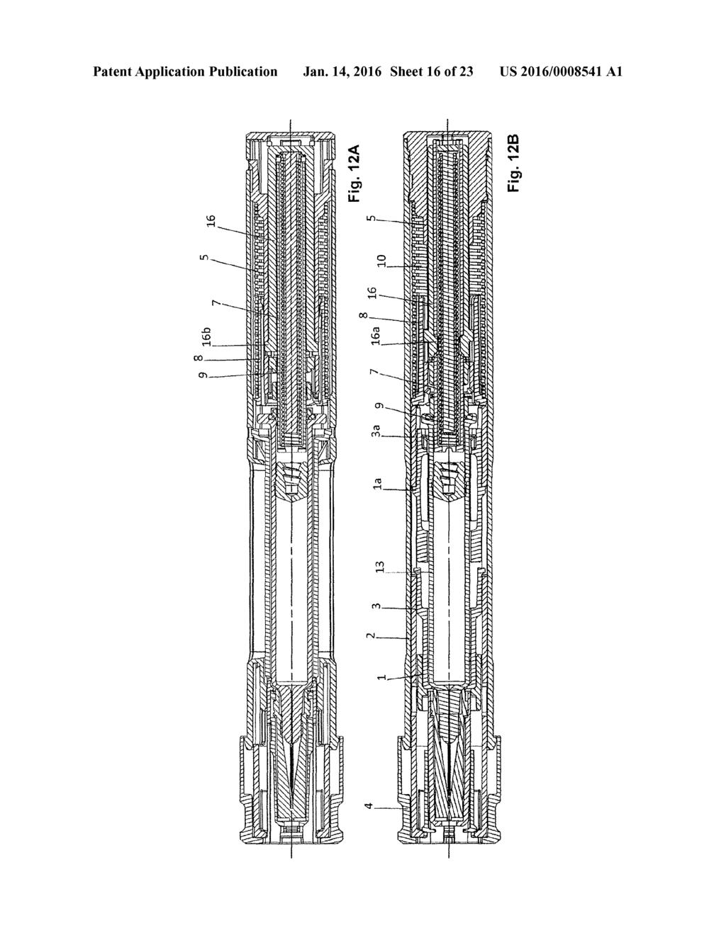
30 Jan. 14, 2016 ing during this displacement. If the locking sleeve 8 has been pushed to such an extent that the cam 5c comes to a stop at the bevel 8i on the proximal end of the groove 8c, as shown in FIGS. 3F and 4F, then further pressure exerted on the locking sleeve 8, in the distal direction, leads to a further rotation of the locking sleeve 8 in the direction shown by the arrow P (FIGS.3F, 4F and 3G, 4G), wherein the cam 5c lines up at the step 8f of the locking sleeve 8 and thus, prevents a pushing back of the locking sleeve 8 and the needle protective sleeve in the proximal direction (in FIG. 4H, to the right) A centering cam 3c, provided on an individual arm 3a of the needle protective sleeve 3 engages, in this state, in a centering groove 8e of the locking sleeve 8 and thus prevents the locking sleeve 8 from rotating back. Thus, in this state, the needle protective sleeve 3 is pushed out beyond the needle 14 and secured against a pushing back by the cam 5c which lines up at the step 8f of the locking path 8c FIG. 8 shows an exploded view of a second embodi ment of an injection device FIGS. 9A and 9B show longitudinal cross-sectional views rotated relative to one another, by 90, in the delivery state. The injection spring 9 is pretensioned between the piston rod 7 and the end cap 12. A release sleeve 16 lies, toward the front via ribs 16c, on the mechanism holder 5. The mechanism holder 5 and the end cap 12 are firmly connected with one another. The piston rod 7 is held, in the distal direc tion, by a triggering Snaps 16a of the release sleeve 16 and is secured by means of the locking sleeve 8. A cam 5c of the mechanism holder 5 engages with an axially running groove 8a of the locking sleeve 8 and prevents a twisting of the locking sleeve 8, relative to the mechanism holder The needle protective sleeve spring 10 is preten sioned between the locking sleeve 8 and the release sleeve 16. The mechanism holder 5 and the end cap 12 are stationary in the housing and are connected with the housing 2, for example, with Snaps or by locking in place The locking sleeve 8 lies on straps or arms 3a of the needle protective sleeve 3, which is held, toward the front via a cam 1a, on the syringe holder 1. The release sleeve 16 is held, toward the back via the triggering Snaps 16a of the release sleeve 16, secured by the locking sleeve 8, on the piston rod Just as described in the first embodiment, the Syringe 13 is secured by means of a shoulder Support 1b and by means of a ring or a housing tapering 2b The removal of the needle protective cap 4 is like wise carried out as described in the first embodiment example FIGS. 10A and 10B show longitudinal cross-sec tional views of the injection device, rotated, relative to one another, by 90, in the pierced state, if the injection device is pressed on the injection site. The needle protective sleeve 3 is pressed into the housing 2 to the stop 2c, while the needle is inserted into the injection site. The needle protective sleeve 3 displaces the locking sleeve 8, relative to the mechanism holder 5 and the release sleeve 16, wherein the needle pro tective sleeve spring 10 is tensed or compressed The injection is triggered by the complete insertion of the needle protective sleeve 3 into the housing 2. The locking sleeve 8 is thereby pushed in the proximal direction (in FIG. 10, to the right), relative to the housing 2, the mecha nism holder 5, and the release sleeve 16, wherein the trigger ing Snaps 16a are released. By the force of the injection spring 9, the triggering Snaps 16a are pressed and free in a distal direction to the front, against the movement of the piston rod 7. The release sleeve 16 is then held toward the rear, on the mechanism holder 5, via the snap arms 16b. I0082 FIGS. 11A and 11B show longitudinal cross-sec tional views of the injection device rotated relative to one another by 90 after the dispensing and after the click for the signaling of the end of the injection has been carried out (end-of-injection click). The piston rod 7 was thereby moved in the distal direction by the force of the injection spring 9. wherein the piston rod presses on the stopper 13a and moves it in the distal direction until it is at the end of the glass body of the syringe 13. At its proximal end, the piston rod 7 has a slit 7b, wherein the snap arms 16b of the release sleeve at the end of the injection are released and the blocking of the release sleeve 16 is lifted toward the rear. I0083. As soon as the snap arms 16b of the release sleeve 16 are released by the slit 7b of the piston rod 7, the snap arms 16b are deflected, wherein the release sleeve 16 is moved to the rear by the force of the needle protective sleeve spring 10 and strikes the bottom 12c of the end cap 12 and produces the end click. I0084. The needle protective locking takes place in the same manner as described in the first embodiment example, wherein the deflected triggering arms are located on the release sleeve 16 and not on the click pin 6, so that in this regard, reference is made to the above description. I0085 FIGS. 12A and 12B show longitudinal cross-sec tional views of a third embodiment of an injection device rotated relative to one another by 90 in the delivery state. The injection spring 9 is pretensioned between the piston rod 7 and the release sleeve 16. The release sleeve 16 is held by the snap arms 16b on the mechanism holder 5 and secured by means of the piston rod 7. The piston rod 7 is held toward the front by the triggering Snaps 16a and secured by means of the locking sleeve 8. The cam 5c of the mechanism holder 5 engages with the axially running groove 8a of the locking sleeve 8 and prevents a twisting of the locking sleeve 8, relative to the mechanism holder 5, which is stationary in the housing. I0086. The needle protective sleeve spring 10 is preten sioned between the locking sleeve 8 and the mechanism holder 5. The mechanism holder 5 is locked by snaps with the housing 2. The locking sleeve 8 lies on the arms 3a of the needle protective sleeve 3, which is held toward the front on the Syringe holder 1 via the cams 1 a. I0087 As described in the embodiment above, the syringe 13 is supported in the Syringe holder 1 and the housing 2. I0088. The removal of the cap removal element 4 for the removal of the needle protective cap 15 takes place as described above. I0089 FIGS. 13A and 13B show longitudinal cross-sec tional views of the injection device rotated relative to one another by 90 which was pressed on the injection site; the contents of the Syringe were dispensed and signaling of the end of the injection was carried out. (0090 First the needle 14 is inserted. The needle protective sleeve 3 is pressed into the housing 2 to the stop 2c. The needle protective sleeve 3 displaces the locking sleeve 8 rela tive to the mechanism holder 5 and the release sleeve 16, wherein the needle protective sleeve spring 10 is tensed The injection is triggered by the complete pushing in of the needle protective sleeve 3 into the housing 2. The locking sleeve 8 is thereby pushed in the proximal direction, relative to the housing 2, the mechanism holder 5, and the
31 Jan. 14, 2016 release sleeve 16, wherein the triggering Snaps 16a are released. By the force of the injection spring 9, the triggering Snaps 16a are pressed and freed to the front, against the movement of the piston rod By the force of the injection spring 9, the piston rod 7 was moved in the distal direction, wherein the piston rod 7 presses on the stopper 13a and moves it to such an extent in the distal direction that it is next to the end of the glass body of the syringe 13. On its proximal end, the piston rod 7 has a slit 7c, wherein the snap arms 16b of the release sleeve 16 are released at the end of the injection and the blocking of the release sleeve 16 is lifted in the proximal direction or toward the rear As soon as the snap arms 16b of the release sleeve 16 are released by the slit 7c of the piston rod 7, the snap arms 16b are deflected, wherein the release sleeve 16 is moved in the proximal direction by the force of the injection spring 9 and strikes the bottom 5b of the mechanism holder 5 and produces the end click The needle protective locking takes place in the same manner as described in the second embodiment example FIG. 14a shows a longitudinal cross-sectional view of another embodiment of an injection device in the delivery state, in which the injection spring 9 lies, on its distal end, on the inside of the piston rod 7. On its proximal end, the injec tion spring 9 is next to a holding sleeve 18, which is stationary in the housing, which surrounds a click pin 20 and radially, on a proximal site with engagement arms 18c, through openings of piston rod7, engages with them. The click pin 20, provided for the generation of the end click, is pressed, in the proximal direction (in FIG. 14A, to the right), on the holding sleeve 18, via a syringe spring 19, which presses on distal end Surfaces of click pin arms 20A, wherein the end cap 12 can be a part of the holding sleeve 18. The syringe spring 19 is supported, in the proximal direction, on the arms 20a of the click pin 20 and presses, in the distal direction, on the Syringe 13, in order Support it securely in the Syringe holder 1 by the acting pressure produced in the distal direction. The arms 20a of the click pin 20 are engaged in openings 7a of the piston rod 7 by means of cams 20b that protrude radially inwards and can be entrained in a distally directed movement of the piston rod 7. so that the piston rod 7 first entrains the click pin 20 in a distal movement from the delivery state shown in FIG. 14A. A loosening of the holding connection 7a, 20b by the radial release of the arms 20a is prevented by the holding sleeve 18 Surrounding the click pin If the housing 2 of the injection device is pressed so far on an injection site that the needle protective sleeve 3 was almost completely, or completely, pushed into the housing 2. as shown in FIG. 14B, the automatic injection is triggered A release sleeve 22 is thereby axially pushed, in the proximal direction, against the force of the needle protective sleeve spring 10 within the housing 2 by the adjacent arms 3a of the needle protective sleeve 3 to such an extent that a holding element of the holding sleeve 18, which engages in the piston rod 7, is released Since the piston rod 7 is acted on by the injection spring 9 in the distal direction, relative to the housing 2, the then released piston rod 7 can be moved, in the distal direc tion, to the stopper 13a of the syringe 13 and can move this stopper 13a into the syringe 13, in order to carry out the dispensing. During the dispensing, the click pin 20 is entrained by the piston rod 7, until the arms 20a of the click pin can deflect radially in the free position 18a of the holding sleeve 18 and be held on the holding sleeve 18 by this inter vention of the cams 20c that lie radially and externally on the arms 20a. A release of the arms 20a of the click pin 20, directed radially inwards, by the piston rod 7, lying on the inside on the cams 20b, is impossible until the piston rod 7 has been moved, in the distal direction, to such an extent that the complete dispensing has been carried out At the end of the dispensing, the arms 20a of the click pin 20 move radially inwards, since the piston rod 7 was moved, in the distal direction, to such an extent that either, in accordance with a non-depicted embodiment, the piston rod was already completely moved past the cam 20b, or, as shown in FIG. 14B, the inside cams 20b can be deflected back into openings or free positions on the piston rod 7. The click pin is thus no longer held by cams 20c or 20b and accelerates, in the proximal direction, due to the pretensioned syringe spring 19. in order to strike the holding sleeve 18 or, alternatively, the end cap 12 (not depicted) and thus produce an end click Sound FIG. 15A shows another embodiment of a func tional unit for the production of an end click. An injection spring is thereby placed under torsional stress between the piston rod 7 and a stabilization pin or the holding sleeve 18. The stabilization pin lies on the bottoms of the holding sleeve 18 and runs axially within the injection spring and is secured against twisting with the holding sleeve The piston rod 7 is conducted linearly in a linear guide 18bby means of a linear guide element 7fin the holding sleeve After the injection has been carried out by an axially forwards directed pushing out of the piston rod 7 from the holding sleeve, as shown in FIG. 15B, the piston rod 7 is decoupled by the movement of the linear guide element 7f out of the linear guide 18b. By the torsion moment of the injection spring 9, the piston rod 7 is rotated in the direction defined by the arrow indicating the rotational direction D and with a stop element 7h will strike, in the circumferential direction, against the holding sleeve 18 or a linear guide groove inner Surface, wherein an end click can be produced Optionally, the piston rod 7 can thereby also rotate on the stopper 13a of the syringe FIG. 16A shows another embodiment of a func tional unit for the production of an end click, wherein the energy for the end click is made available by the needle protective sleeve spring 10. The needle protective sleeve spring 10 is pretensioned between the release sleeve 22 in FIG. 16A and the click sleeve 21. The click sleeve 21 has hooks 21a, which engage in the holding sleeve The piston rod 7 has a cam 7g, which presses the hooks 21a of the click sleeve 21, toward the end of the injection, as shown in FIG. 16B, by passing, proximally to distally (in FIG. 16B, from right to left), wherein they hang out from the holding sleeve 18 and thus the coupling of the click sleeve 21 with the holding sleeve 18 is loosened The click sleeve 21 is accelerated or moved, by the needle protective sleeve spring 10, toward the rear or, in a proximal direction, to a stop on the holding sleeve 18, wherein the end click is produced. What is claimed is: 1. A device for administering a substance, comprising: a release element, by means of which the Substance can be released; a displaceable protective element for the release element;

32 Jan. 14, 2016 a drive element coupled with the protective element; and a first feedback element coupled to the drive element, wherein the first feedback element produces an end signal when a predefined quantity of the Substance has been released. 2. The device according to claim 1, wherein a second feedback element produces a start signal at a beginning of the release of the predefined quantity of Substance. 3. The device according to claim 2, further comprising a second drive element for releasing the Substance. 4. The device according to claim 3, wherein the second feedback element is driven by the second drive element. 5. The device according to claim 4, further comprising a locking sleeve coupled with the second feedback element prior to the beginning of the release, wherein movement of the displaceable protective element in a proximal direction slaves the locking sleeve in movement and releases the coupling such that the second drive element moves the second feed back element in a proximal direction thereby causing the start signal to be produced. 6. The device according to claim 2, wherein one or more of the first or the second feedback element strikes a housing or a stationary element in a housing to produce one or more of the respective start or end signal. 7. The device according to claim 2, further comprising a dampening element or a modulation element, by means of which one or more of the start or end signal produced is modified. 8. The device according to claim 2, wherein one or more of the start signal or the end signals is or more of an acoustical, an optical, or a tactile signal. 9. The device according to claim 1, wherein the protective element covers or surrounds the release element before and/or after the substance is released. 10. The device according to claim 1, further comprising a releasable holding device configured to hold the first feed back element until the predefined quantity of Substance has been released. 11. The device according to claim 10, wherein the releas able holding device and a piston rod cooperate to hold the first feedback element. 12. The device according to claim 11, wherein upon the piston rod moving in a distal direction to release the pre defined quantity of substance, the drive element moves the first feedback element in a proximal direction thereby causing the end signal to be produced. 13. The device according to claim 12, wherein after the predefined quantity of substance has been released, the drive element moves the displaceable protective element in the distal direction to cover the release element. 14. The device according to claim 13, further comprising: a second feedback element configured to produce a start signal at a beginning of the release of the predefined quantity of Substance; and a second drive element for releasing the Substance and for driving the second feedback element. 15. The device according to claim 14, further comprising a locking sleeve coupled with the second feedback element prior to the beginning of the release, wherein movement of the displaceable protective element in the proximal direction slaves the locking sleeve in movement and releases the cou pling Such that the second drive element moves the second feedback element in the proximal direction thereby causing the start signal to be produced. 16. The device according to claim 1, wherein the first feedback element is configured to move one or more of lon gitudinally along the device or rotationally in the device. 17. The device according to claim 1, wherein the second drive element releases energy to the drive element before, during, or after the predefined quantity of substance has been released. 18. A method for releasing a substance from a device, whereby the substance is automatically released by means of a first drive element and a feedback signal for the signaling of a completed Substance release is produced by means of a feedback element driven by a separate, second drive element. 19. The method according to claim 18, wherein the first drive element releases energy to the second drive element before, during, or after the Substance release. k k k k k
(12) Patent Application Publication (10) Pub. No.: US 2008/ A1
 Patent Application Publication (10) Pub. No.: US 2008/ A1") (19) United States US 20080000052A1 (12) Patent Application Publication (10) Pub. No.: US 2008/0000052 A1 Hong et al. (43) Pub. Date: Jan. 3, 2008 (54) REFRIGERATOR (75) Inventors: Dae Jin Hong, Jangseong-gun
(19) United States US 20080000052A1 (12) Patent Application Publication (10) Pub. No.: US 2008/0000052 A1 Hong et al. (43) Pub. Date: Jan. 3, 2008 (54) REFRIGERATOR (75) Inventors: Dae Jin Hong, Jangseong-gun
(12) Patent Application Publication (10) Pub. No.: US 2008/ A1
 Patent Application Publication (10) Pub. No.: US 2008/ A1") US 20080264.753A1 (19) United States (12) Patent Application Publication (10) Pub. No.: US 2008/0264753 A1 Rollion et al. (43) Pub. Date: Oct. 30, 2008 (54) FRICTIONAL CLUTCH WITH O-RING Publication Classification
US 20080264.753A1 (19) United States (12) Patent Application Publication (10) Pub. No.: US 2008/0264753 A1 Rollion et al. (43) Pub. Date: Oct. 30, 2008 (54) FRICTIONAL CLUTCH WITH O-RING Publication Classification
(12) Patent Application Publication (10) Pub. No.: US 2002/ A1
 Patent Application Publication (10) Pub. No.: US 2002/ A1") (19) United States US 20020052578A1 (12) Patent Application Publication (10) Pub. No.: US 2002/0052578A1 Moller (43) Pub. Date: May 2, 2002 (54) INJECTION DEVICE (30) Foreign Application Priority Data
(19) United States US 20020052578A1 (12) Patent Application Publication (10) Pub. No.: US 2002/0052578A1 Moller (43) Pub. Date: May 2, 2002 (54) INJECTION DEVICE (30) Foreign Application Priority Data
(12) Patent Application Publication (10) Pub. No.: US 2001/ A1
 Patent Application Publication (10) Pub. No.: US 2001/ A1") (19) United States US 2001 0023637A1 (12) Patent Application Publication (10) Pub. No.: US 2001/0023637 A1 Klitmose et al. (43) Pub. Date: Sep. 27, 2001 (54) FLEXIBLE PISTON ROD (76) Inventors: Lars Peter
(19) United States US 2001 0023637A1 (12) Patent Application Publication (10) Pub. No.: US 2001/0023637 A1 Klitmose et al. (43) Pub. Date: Sep. 27, 2001 (54) FLEXIBLE PISTON ROD (76) Inventors: Lars Peter
(12) Patent Application Publication (10) Pub. No.: US 2005/ A1
 Patent Application Publication (10) Pub. No.: US 2005/ A1") (19) United States US 2005OO64994A1 (12) Patent Application Publication (10) Pub. No.: Matsumoto (43) Pub. Date: Mar. 24, 2005 (54) STATIONARY BIKE (52) U.S. Cl.... 482/8 (76) Inventor: Masaaki Matsumoto,
(19) United States US 2005OO64994A1 (12) Patent Application Publication (10) Pub. No.: Matsumoto (43) Pub. Date: Mar. 24, 2005 (54) STATIONARY BIKE (52) U.S. Cl.... 482/8 (76) Inventor: Masaaki Matsumoto,
(12) United States Patent (10) Patent No.: US 8,215,503 B2. Appel et al. (45) Date of Patent: Jul. 10, 2012
 United States Patent (10) Patent No.: US 8,215,503 B2. Appel et al. (45) Date of Patent: Jul. 10, 2012") US008215503B2 (12) United States Patent (10) Patent No.: US 8,215,503 B2 Appel et al. (45) Date of Patent: Jul. 10, 2012 (54) CRANE WITH TELESCOPIC BOOM 3,921,819 A * 1 1/1975 Spain... 212,349 4,394,108
US008215503B2 (12) United States Patent (10) Patent No.: US 8,215,503 B2 Appel et al. (45) Date of Patent: Jul. 10, 2012 (54) CRANE WITH TELESCOPIC BOOM 3,921,819 A * 1 1/1975 Spain... 212,349 4,394,108
(12) Patent Application Publication (10) Pub. No.: US 2002/ A1
 Patent Application Publication (10) Pub. No.: US 2002/ A1") (19) United States US 2002O152831A1 (12) Patent Application Publication (10) Pub. No.: US 2002/0152831 A1 Sakamoto et al. (43) Pub. Date: Oct. 24, 2002 (54) ACCELERATOR PEDAL DEVICE (76) Inventors: Kazunori
(19) United States US 2002O152831A1 (12) Patent Application Publication (10) Pub. No.: US 2002/0152831 A1 Sakamoto et al. (43) Pub. Date: Oct. 24, 2002 (54) ACCELERATOR PEDAL DEVICE (76) Inventors: Kazunori
(12) Patent Application Publication (10) Pub. No.: US 2013/ A1
 Patent Application Publication (10) Pub. No.: US 2013/ A1") (19) United States (12) Patent Application Publication (10) Pub. No.: US 2013/0340205 A1 CHUAH US 2013 0340205A1 (43) Pub. Date: Dec. 26, 2013 (54) (76) (21) (22) (60) BABY STROLLER FOLDING MECHANISM Inventor:
(19) United States (12) Patent Application Publication (10) Pub. No.: US 2013/0340205 A1 CHUAH US 2013 0340205A1 (43) Pub. Date: Dec. 26, 2013 (54) (76) (21) (22) (60) BABY STROLLER FOLDING MECHANISM Inventor:
(12) Patent Application Publication (10) Pub. No.: US 2012/ A1
 Patent Application Publication (10) Pub. No.: US 2012/ A1") (19) United States US 2012O181130A1 (12) Patent Application Publication (10) Pub. No.: US 2012/0181130 A1 Fukunaga (43) Pub. Date: Jul.19, 2012 (54) TORQUE CONVERTER Publication Classification 51) Int.
(19) United States US 2012O181130A1 (12) Patent Application Publication (10) Pub. No.: US 2012/0181130 A1 Fukunaga (43) Pub. Date: Jul.19, 2012 (54) TORQUE CONVERTER Publication Classification 51) Int.
(12) (10) Patent No.: US 6,915,721 B2. Hsu et al. (45) Date of Patent: Jul. 12, 2005
 (10) Patent No.: US 6,915,721 B2. Hsu et al. (45) Date of Patent: Jul. 12, 2005") United States Patent USOO6915721B2 (12) (10) Patent No.: US 6,915,721 B2 Hsu et al. (45) Date of Patent: Jul. 12, 2005 (54) CORDLESS RATCHET WRENCH 6,311,583 B1 11/2001 Izumisawa... 81/57.13 6,715,380
United States Patent USOO6915721B2 (12) (10) Patent No.: US 6,915,721 B2 Hsu et al. (45) Date of Patent: Jul. 12, 2005 (54) CORDLESS RATCHET WRENCH 6,311,583 B1 11/2001 Izumisawa... 81/57.13 6,715,380
(12) Patent Application Publication (10) Pub. No.: US 2013/ A1
 Patent Application Publication (10) Pub. No.: US 2013/ A1") (19) United States US 2013 0319168A1 (12) Patent Application Publication (10) Pub. No.: US 2013/0319168A1 Pingani et al. (43) Pub. Date: Dec. 5, 2013 (54) DETENT MECHANISM FOR A SLIDING (52) U.S. Cl. VALVE
(19) United States US 2013 0319168A1 (12) Patent Application Publication (10) Pub. No.: US 2013/0319168A1 Pingani et al. (43) Pub. Date: Dec. 5, 2013 (54) DETENT MECHANISM FOR A SLIDING (52) U.S. Cl. VALVE
(12) Patent Application Publication (10) Pub. No.: US 2014/ A1. Durand (43) Pub. Date: Oct. 30, 2014 PUMP CPC... F04D 13/022 (2013.
 Patent Application Publication (10) Pub. No.: US 2014/ A1. Durand (43) Pub. Date: Oct. 30, 2014 PUMP CPC... F04D 13/022 (2013.") US 20140322042A1 (19) United States (12) Patent Application Publication (10) Pub. No.: US 2014/0322042 A1 Durand (43) Pub. Date: Oct. 30, 2014 (54) SWITCHABLE AUTOMOTIVE COOLANT (52) U.S. Cl. PUMP CPC...
US 20140322042A1 (19) United States (12) Patent Application Publication (10) Pub. No.: US 2014/0322042 A1 Durand (43) Pub. Date: Oct. 30, 2014 (54) SWITCHABLE AUTOMOTIVE COOLANT (52) U.S. Cl. PUMP CPC...
(12) Patent Application Publication (10) Pub. No.: US 2002/ A1
 Patent Application Publication (10) Pub. No.: US 2002/ A1") (19) United States US 2002O00861 OA1 (12) Patent Application Publication (10) Pub. No.: US 2002/0008610 A1 PetersOn (43) Pub. Date: Jan. 24, 2002 (54) KEY FOB WITH SLIDABLE COVER (75) Inventor: John Peterson,
(19) United States US 2002O00861 OA1 (12) Patent Application Publication (10) Pub. No.: US 2002/0008610 A1 PetersOn (43) Pub. Date: Jan. 24, 2002 (54) KEY FOB WITH SLIDABLE COVER (75) Inventor: John Peterson,
(12) Patent Application Publication (10) Pub. No.: US 2007/ A1
 Patent Application Publication (10) Pub. No.: US 2007/ A1") US 20070257638A1 (19) United States (12) Patent Application Publication (10) Pub. No.: US 2007/0257638A1 Amend et al. (43) Pub. Date: Nov. 8, 2007 (54) TWIST LOCK BATTERY INTERFACE FOR (52) U.S. Cl....
US 20070257638A1 (19) United States (12) Patent Application Publication (10) Pub. No.: US 2007/0257638A1 Amend et al. (43) Pub. Date: Nov. 8, 2007 (54) TWIST LOCK BATTERY INTERFACE FOR (52) U.S. Cl....
Phillips (45) Date of Patent: Jun. 10, (54) TRIPLE CLUTCH MULTI-SPEED (58) Field of Classification Search
 Date of Patent: Jun. 10, (54) TRIPLE CLUTCH MULTI-SPEED (58) Field of Classification Search") (12) United States Patent US008747274B2 () Patent No.: Phillips () Date of Patent: Jun., 2014 (54) TRIPLE CLUTCH MULTI-SPEED (58) Field of Classification Search TRANSMISSION USPC... 74/3, 331; 475/207
(12) United States Patent US008747274B2 () Patent No.: Phillips () Date of Patent: Jun., 2014 (54) TRIPLE CLUTCH MULTI-SPEED (58) Field of Classification Search TRANSMISSION USPC... 74/3, 331; 475/207
(12) Patent Application Publication (10) Pub. No.: US 2016/ A1
 Patent Application Publication (10) Pub. No.: US 2016/ A1") (19) United States US 2016.0312869A1 (12) Patent Application Publication (10) Pub. No.: US 2016/0312869 A1 WALTER (43) Pub. Date: Oct. 27, 2016 (54) CVT DRIVE TRAIN Publication Classification (71) Applicant:
(19) United States US 2016.0312869A1 (12) Patent Application Publication (10) Pub. No.: US 2016/0312869 A1 WALTER (43) Pub. Date: Oct. 27, 2016 (54) CVT DRIVE TRAIN Publication Classification (71) Applicant:
(12) United States Patent (10) Patent No.: US 6,641,228 B2
 United States Patent (10) Patent No.: US 6,641,228 B2") USOO6641228B2 (12) United States Patent (10) Patent No.: US 6,641,228 B2 Liu (45) Date of Patent: Nov. 4, 2003 (54) DETACHABLE FRONT WHEEL STRUCTURE (56) References Cited OF GOLF CART U.S. PATENT DOCUMENTS
USOO6641228B2 (12) United States Patent (10) Patent No.: US 6,641,228 B2 Liu (45) Date of Patent: Nov. 4, 2003 (54) DETACHABLE FRONT WHEEL STRUCTURE (56) References Cited OF GOLF CART U.S. PATENT DOCUMENTS
(12) Patent Application Publication (10) Pub. No.: US 2003/ A1
 Patent Application Publication (10) Pub. No.: US 2003/ A1") US 2003O190837A1 (19) United States (12) Patent Application Publication (10) Pub. No.: US 2003/0190837 A1 W (43) Pub. Date: Oct. 9, 2003 (54) BATTERY HOLDER HAVING MEANS FOR (52) U.S. Cl.... 439/500 SECURELY
US 2003O190837A1 (19) United States (12) Patent Application Publication (10) Pub. No.: US 2003/0190837 A1 W (43) Pub. Date: Oct. 9, 2003 (54) BATTERY HOLDER HAVING MEANS FOR (52) U.S. Cl.... 439/500 SECURELY
IIIHIIII 5,509,863. United States Patent (19) Månsson et al. Apr. 23, Patent Number: 45) Date of Patent:
 Månsson et al. Apr. 23, Patent Number: 45) Date of Patent:") United States Patent (19) Månsson et al. 54) TRANSMISSION DEVICE, ESPECIALLY FOR BOAT MOTORS 75 Inventors: Staffan Månsson, Hjalteby; Benny Hedlund, Hönö, both of Sweden 73 Assignee: AB Volvo Penta, Gothenburg,
United States Patent (19) Månsson et al. 54) TRANSMISSION DEVICE, ESPECIALLY FOR BOAT MOTORS 75 Inventors: Staffan Månsson, Hjalteby; Benny Hedlund, Hönö, both of Sweden 73 Assignee: AB Volvo Penta, Gothenburg,
(12) Patent Application Publication (10) Pub. No.: US 2009/ A1
 Patent Application Publication (10) Pub. No.: US 2009/ A1") (19) United States (12) Patent Application Publication (10) Pub. No.: US 2009/0157272 A1 Uhler et al. US 2009015.7272A1 (43) Pub. Date: (54) (75) (73) (21) (22) (60) FOUR-PASSAGE MULTIFUNCTION TOROUE CONVERTER
(19) United States (12) Patent Application Publication (10) Pub. No.: US 2009/0157272 A1 Uhler et al. US 2009015.7272A1 (43) Pub. Date: (54) (75) (73) (21) (22) (60) FOUR-PASSAGE MULTIFUNCTION TOROUE CONVERTER
(12) Patent Application Publication (10) Pub. No.: US 2012/ A1. Underbakke et al. (43) Pub. Date: Jun. 28, 2012
 Patent Application Publication (10) Pub. No.: US 2012/ A1. Underbakke et al. (43) Pub. Date: Jun. 28, 2012") US 2012O163742A1 (19) United States (12) Patent Application Publication (10) Pub. No.: US 2012/0163742 A1 Underbakke et al. (43) Pub. Date: Jun. 28, 2012 (54) AXIAL GAS THRUST BEARING FOR (30) Foreign
US 2012O163742A1 (19) United States (12) Patent Application Publication (10) Pub. No.: US 2012/0163742 A1 Underbakke et al. (43) Pub. Date: Jun. 28, 2012 (54) AXIAL GAS THRUST BEARING FOR (30) Foreign
United States Patent (19)
") United States Patent (19) Belanger et al. 4 MECHANISM FOR GLUE GUN (76) Inventors: (21) 22 (1) 2) 8 (6) Richard W. Belanger, 2 Collins St., Amesbury, Mass. 01913; Peter S. Melendy, 11 Crestview Dr., Exeter,
United States Patent (19) Belanger et al. 4 MECHANISM FOR GLUE GUN (76) Inventors: (21) 22 (1) 2) 8 (6) Richard W. Belanger, 2 Collins St., Amesbury, Mass. 01913; Peter S. Melendy, 11 Crestview Dr., Exeter,
22 Š. (12) Patent Application Publication (10) Pub. No.: US 2008/ A1 SSSNS. (19) United States Z SN a. (43) Pub.
 Patent Application Publication (10) Pub. No.: US 2008/ A1 SSSNS. (19) United States Z SN a. (43) Pub.") (19) United States US 200801 05234A1 (12) Patent Application Publication (10) Pub. No.: US 2008/0105234 A1 Yoshizumi et al. (43) Pub. Date: (54) FUEL INJECTION PUMP EQUIPPED WITH ROTARY DEFLECTOR (76)
(19) United States US 200801 05234A1 (12) Patent Application Publication (10) Pub. No.: US 2008/0105234 A1 Yoshizumi et al. (43) Pub. Date: (54) FUEL INJECTION PUMP EQUIPPED WITH ROTARY DEFLECTOR (76)
1.34. (12) Patent Application Publication (10) Pub. No.: US 2016/ A1 A) 1.5 N. \a age , \ N (19) United States
 Patent Application Publication (10) Pub. No.: US 2016/ A1 A) 1.5 N. \a age , \ N (19) United States") (19) United States US 2016.022O767A1 (12) Patent Application Publication (10) Pub. No.: US 2016/0220767 A1 Roberts et al. (43) Pub. Date: Aug. 4, 2016 (54) (71) (72) (21) (22) (63) (30) SAFETY DEVICE FOR
(19) United States US 2016.022O767A1 (12) Patent Application Publication (10) Pub. No.: US 2016/0220767 A1 Roberts et al. (43) Pub. Date: Aug. 4, 2016 (54) (71) (72) (21) (22) (63) (30) SAFETY DEVICE FOR
(12) Patent Application Publication (10) Pub. No.: US 2004/ A1
 Patent Application Publication (10) Pub. No.: US 2004/ A1") US 2004.00431 O2A1 (19) United States (12) Patent Application Publication (10) Pub. No.: US 2004/0043102 A1 H0 et al. (43) Pub. Date: Mar. 4, 2004 (54) ALIGNMENT COLLAR FOR A NOZZLE (52) U.S. Cl.... 425/567
US 2004.00431 O2A1 (19) United States (12) Patent Application Publication (10) Pub. No.: US 2004/0043102 A1 H0 et al. (43) Pub. Date: Mar. 4, 2004 (54) ALIGNMENT COLLAR FOR A NOZZLE (52) U.S. Cl.... 425/567
US 7, B2. Loughrin et al. Jan. 1, (45) Date of Patent: (10) Patent No.: and/or the driven component. (12) United States Patent (54) (75)
 Date of Patent: (10) Patent No.: and/or the driven component. (12) United States Patent (54) (75)") USOO7314416B2 (12) United States Patent Loughrin et al. (10) Patent No.: (45) Date of Patent: US 7,314.416 B2 Jan. 1, 2008 (54) (75) (73) (*) (21) (22) (65) (51) (52) (58) (56) DRIVE SHAFT COUPLNG Inventors:
USOO7314416B2 (12) United States Patent Loughrin et al. (10) Patent No.: (45) Date of Patent: US 7,314.416 B2 Jan. 1, 2008 (54) (75) (73) (*) (21) (22) (65) (51) (52) (58) (56) DRIVE SHAFT COUPLNG Inventors:
(12) Patent Application Publication (10) Pub. No.: US 2006/ A1
 Patent Application Publication (10) Pub. No.: US 2006/ A1") US 2006O131873A1 (19) United States (12) Patent Application Publication (10) Pub. No.: Klingbail et al. (43) Pub. Date: Jun. 22, 2006 (54) HIGH PRESSURE SWIVEL JOINT Publication Classification (76) Inventors:
US 2006O131873A1 (19) United States (12) Patent Application Publication (10) Pub. No.: Klingbail et al. (43) Pub. Date: Jun. 22, 2006 (54) HIGH PRESSURE SWIVEL JOINT Publication Classification (76) Inventors:
(21) Appl.No.: 14/288,967
 Appl.No.: 14/288,967") US 20150075332Al (19) United States (12) Patent Application Publication (10) Pub. No.: US 2015/0075332 A1 CHEN (43) Pub. Date: Mar. 19, 2015 (54) PASS-THRU RATCHET WRENCH (71) Applicant: Chia-Yu CHEN,
US 20150075332Al (19) United States (12) Patent Application Publication (10) Pub. No.: US 2015/0075332 A1 CHEN (43) Pub. Date: Mar. 19, 2015 (54) PASS-THRU RATCHET WRENCH (71) Applicant: Chia-Yu CHEN,
(12) United States Patent (10) Patent No.: US 6,626,061 B2. Sakamoto et al. (45) Date of Patent: Sep. 30, 2003
 United States Patent (10) Patent No.: US 6,626,061 B2. Sakamoto et al. (45) Date of Patent: Sep. 30, 2003") USOO6626061B2 (12) United States Patent (10) Patent No.: Sakamoto et al. (45) Date of Patent: Sep. 30, 2003 (54) ACCELERATOR PEDAL DEVICE 6,276,229 B1 * 8/2001 Gohring et al... 74/513 6,289,762 B1 9/2001
USOO6626061B2 (12) United States Patent (10) Patent No.: Sakamoto et al. (45) Date of Patent: Sep. 30, 2003 (54) ACCELERATOR PEDAL DEVICE 6,276,229 B1 * 8/2001 Gohring et al... 74/513 6,289,762 B1 9/2001
(12) Patent Application Publication (10) Pub. No.: US 2017/ A1
 Patent Application Publication (10) Pub. No.: US 2017/ A1") (19) United States US 201701.20388A1 (12) Patent Application Publication (10) Pub. No.: US 2017/0120388 A1 Luo et al. (43) Pub. Date: May 4, 2017 (54) DEVICE AND METHOD FOR LASER Publication Classification
(19) United States US 201701.20388A1 (12) Patent Application Publication (10) Pub. No.: US 2017/0120388 A1 Luo et al. (43) Pub. Date: May 4, 2017 (54) DEVICE AND METHOD FOR LASER Publication Classification
(12) Patent Application Publication (10) Pub. No.: US 2014/ A1
 Patent Application Publication (10) Pub. No.: US 2014/ A1") (19) United States US 2014O124322A1 (12) Patent Application Publication (10) Pub. No.: US 2014/0124322 A1 Cimatti (43) Pub. Date: May 8, 2014 (54) NORMALLY CLOSED AUTOMOTIVE (52) U.S. Cl. CLUTCH WITH HYDRAULC
(19) United States US 2014O124322A1 (12) Patent Application Publication (10) Pub. No.: US 2014/0124322 A1 Cimatti (43) Pub. Date: May 8, 2014 (54) NORMALLY CLOSED AUTOMOTIVE (52) U.S. Cl. CLUTCH WITH HYDRAULC
(12) Patent Application Publication (10) Pub. No.: US 2012/ A1
 Patent Application Publication (10) Pub. No.: US 2012/ A1") (19) United States (12) Patent Application Publication (10) Pub. No.: US 2012/0078225A1 Zivkovic et al. US 20120078225A1 (43) Pub. Date: Mar. 29, 2012 (54) (75) (73) (21) (22) DUAL CHAMBER SYRINGE WITH
(19) United States (12) Patent Application Publication (10) Pub. No.: US 2012/0078225A1 Zivkovic et al. US 20120078225A1 (43) Pub. Date: Mar. 29, 2012 (54) (75) (73) (21) (22) DUAL CHAMBER SYRINGE WITH
(12) Patent Application Publication (10) Pub. No.: US 2011/ A1
 Patent Application Publication (10) Pub. No.: US 2011/ A1") (19) United States (12) Patent Application Publication (10) Pub. No.: US 2011/0226455A1 Al-Anizi et al. US 2011 0226455A1 (43) Pub. Date: Sep. 22, 2011 (54) (75) (73) (21) (22) SLOTTED IMPINGEMENT PLATES
(19) United States (12) Patent Application Publication (10) Pub. No.: US 2011/0226455A1 Al-Anizi et al. US 2011 0226455A1 (43) Pub. Date: Sep. 22, 2011 (54) (75) (73) (21) (22) SLOTTED IMPINGEMENT PLATES
(12) Patent Application Publication (10) Pub. No.: US 2007/ A1
 Patent Application Publication (10) Pub. No.: US 2007/ A1") (19) United States US 20070011840A1 (12) Patent Application Publication (10) Pub. No.: US 2007/0011840 A1 Gilli (43) Pub. Date: Jan. 18, 2007 (54) WINDSCREEN WIPER ARM (75) Inventor: Marco Gilli, Chieri
(19) United States US 20070011840A1 (12) Patent Application Publication (10) Pub. No.: US 2007/0011840 A1 Gilli (43) Pub. Date: Jan. 18, 2007 (54) WINDSCREEN WIPER ARM (75) Inventor: Marco Gilli, Chieri
(12) Patent Application Publication (10) Pub. No.: US 2014/ A1
 Patent Application Publication (10) Pub. No.: US 2014/ A1") (19) United States (12) Patent Application Publication (10) Pub. No.: US 2014/0041841 A1 Huazhao et al. US 20140041841A1 (43) Pub. Date: Feb. 13, 2014 (54) (71) (72) (21) (22) (62) (30) MICRO-CHANNEL HEAT
(19) United States (12) Patent Application Publication (10) Pub. No.: US 2014/0041841 A1 Huazhao et al. US 20140041841A1 (43) Pub. Date: Feb. 13, 2014 (54) (71) (72) (21) (22) (62) (30) MICRO-CHANNEL HEAT
Y-Né Š I/? S - - (12) Patent Application Publication (10) Pub. No.: US 2003/ A1. (19) United States 2S) (43) Pub. Date: Feb. 20, 2003 (54) (75)
 Patent Application Publication (10) Pub. No.: US 2003/ A1. (19) United States 2S) (43) Pub. Date: Feb. 20, 2003 (54) (75)") (19) United States (12) Patent Application Publication (10) Pub. No.: US 2003/0035740 A1 Knoll et al. US 2003.0035740A1 (43) Pub. Date: Feb. 20, 2003 (54) (75) (73) (21) (22) (30) WET TYPE ROTOR PUMP Inventors:
(19) United States (12) Patent Application Publication (10) Pub. No.: US 2003/0035740 A1 Knoll et al. US 2003.0035740A1 (43) Pub. Date: Feb. 20, 2003 (54) (75) (73) (21) (22) (30) WET TYPE ROTOR PUMP Inventors:
(12) Patent Application Publication (10) Pub. No.: US 2010/ A1
 Patent Application Publication (10) Pub. No.: US 2010/ A1") (19) United States US 2010O225192A1 (12) Patent Application Publication (10) Pub. No.: US 2010/0225192 A1 Jeung (43) Pub. Date: Sep. 9, 2010 (54) PRINTED CIRCUIT BOARD AND METHOD Publication Classification
(19) United States US 2010O225192A1 (12) Patent Application Publication (10) Pub. No.: US 2010/0225192 A1 Jeung (43) Pub. Date: Sep. 9, 2010 (54) PRINTED CIRCUIT BOARD AND METHOD Publication Classification
(12) Patent Application Publication (10) Pub. No.: US 2016/ A1
 Patent Application Publication (10) Pub. No.: US 2016/ A1") (19) United States (12) Patent Application Publication (10) Pub. No.: US 2016/0251883 A1 WANG US 2016O251883A1 (43) Pub. Date: Sep. 1, 2016 (54) LOCKING AND UNLOCKING MECHANISM FOR ADOOR LOCK (71) Applicant:
(19) United States (12) Patent Application Publication (10) Pub. No.: US 2016/0251883 A1 WANG US 2016O251883A1 (43) Pub. Date: Sep. 1, 2016 (54) LOCKING AND UNLOCKING MECHANISM FOR ADOOR LOCK (71) Applicant:
A Practical Guide to Free Energy Devices
 A Practical Guide to Free Energy Devices Part PatD20: Last updated: 26th September 2006 Author: Patrick J. Kelly This patent covers a device which is claimed to have a greater output power than the input
(12) Patent Application Publication (10) Pub. No.: US 2013/ A1
 Patent Application Publication (10) Pub. No.: US 2013/ A1") (19) United States (12) Patent Application Publication (10) Pub. No.: US 2013/0139355A1 Lee et al. US 2013 O1393.55A1 (43) Pub. Date: Jun. 6, 2013 (54) (75) (73) (21) (22) (60) HINGEMECHANISMAND FOLDABLE
(19) United States (12) Patent Application Publication (10) Pub. No.: US 2013/0139355A1 Lee et al. US 2013 O1393.55A1 (43) Pub. Date: Jun. 6, 2013 (54) (75) (73) (21) (22) (60) HINGEMECHANISMAND FOLDABLE
(12) United States Patent
 United States Patent") USOO9566386B2 (12) United States Patent Stefanski (10) Patent No.: (45) Date of Patent: Feb. 14, 2017 (54) AUTOMATIC APPLICATOR FOR LIQUID PHARMACEUTICAL PREPARATIONS, PARTICULARLY FOR INSULIN (75) Inventor:
USOO9566386B2 (12) United States Patent Stefanski (10) Patent No.: (45) Date of Patent: Feb. 14, 2017 (54) AUTOMATIC APPLICATOR FOR LIQUID PHARMACEUTICAL PREPARATIONS, PARTICULARLY FOR INSULIN (75) Inventor:
(12) United States Patent
 United States Patent") USOO8042596B2 (12) United States Patent Llagostera Forns (54) (75) (73) (*) (21) (22) (86) (87) (65) (30) (51) (52) (58) ARTICULATION DEVICE FOR AN AWNING ELBOW JOINT Inventor: Sep. 27, 2006 Joan Llagostera
USOO8042596B2 (12) United States Patent Llagostera Forns (54) (75) (73) (*) (21) (22) (86) (87) (65) (30) (51) (52) (58) ARTICULATION DEVICE FOR AN AWNING ELBOW JOINT Inventor: Sep. 27, 2006 Joan Llagostera
(12) Patent Application Publication (10) Pub. No.: US 2010/ A1
 Patent Application Publication (10) Pub. No.: US 2010/ A1") US 2010O282008A1 (19) United States (12) Patent Application Publication (10) Pub. No.: US 2010/0282008 A1 Knudsen et al. (43) Pub. Date: Nov. 11, 2010 (54) LINEAR ACTUATOR (30) Foreign Application Priority
US 2010O282008A1 (19) United States (12) Patent Application Publication (10) Pub. No.: US 2010/0282008 A1 Knudsen et al. (43) Pub. Date: Nov. 11, 2010 (54) LINEAR ACTUATOR (30) Foreign Application Priority
(12) Patent Application Publication (10) Pub. No.: US 2014/ A1
 Patent Application Publication (10) Pub. No.: US 2014/ A1") (19) United States (12) Patent Application Publication (10) Pub. No.: US 2014/0090635 A1 May US 20140090635A1 (43) Pub. Date: Apr. 3, 2014 (54) (71) (72) (73) (21) (22) (60) PROPANETANKFUEL GAUGE FOR BARBECUE
(19) United States (12) Patent Application Publication (10) Pub. No.: US 2014/0090635 A1 May US 20140090635A1 (43) Pub. Date: Apr. 3, 2014 (54) (71) (72) (73) (21) (22) (60) PROPANETANKFUEL GAUGE FOR BARBECUE
(12) Patent Application Publication (10) Pub. No.: US 2009/ A1. Kobayashi et al. (43) Pub. Date: Mar. 5, 2009
 Patent Application Publication (10) Pub. No.: US 2009/ A1. Kobayashi et al. (43) Pub. Date: Mar. 5, 2009") US 20090062784A1 (19) United States (12) Patent Application Publication (10) Pub. No.: US 2009/0062784 A1 Kobayashi et al. (43) Pub. Date: Mar. 5, 2009 (54) NEEDLEELECTRODE DEVICE FOR (30) Foreign Application
US 20090062784A1 (19) United States (12) Patent Application Publication (10) Pub. No.: US 2009/0062784 A1 Kobayashi et al. (43) Pub. Date: Mar. 5, 2009 (54) NEEDLEELECTRODE DEVICE FOR (30) Foreign Application
(12) Patent Application Publication (10) Pub. No.: US 2007/ A1
 Patent Application Publication (10) Pub. No.: US 2007/ A1") (19) United States (12) Patent Application Publication (10) Pub. No.: US 2007/0266837 A1 Nickels et al. US 20070266837A1 (43) Pub. Date: Nov. 22, 2007 (54) CLAMPASSEMBLY (76) Inventors: Richard C. Nickels,
(19) United States (12) Patent Application Publication (10) Pub. No.: US 2007/0266837 A1 Nickels et al. US 20070266837A1 (43) Pub. Date: Nov. 22, 2007 (54) CLAMPASSEMBLY (76) Inventors: Richard C. Nickels,
(12) Patent Application Publication (10) Pub. No.: US 2006/ A1
 Patent Application Publication (10) Pub. No.: US 2006/ A1") (19) United States US 2006.0068960A1 (12) Patent Application Publication (10) Pub. No.: US 2006/0068960 A1 Kopecek (43) Pub. Date: Mar. 30, 2006 (54) DRIVE ASSEMBLIES Publication Classification (75) Inventor:
(19) United States US 2006.0068960A1 (12) Patent Application Publication (10) Pub. No.: US 2006/0068960 A1 Kopecek (43) Pub. Date: Mar. 30, 2006 (54) DRIVE ASSEMBLIES Publication Classification (75) Inventor:
(12) United States Patent
 United States Patent") (12) United States Patent USOO6989498B1 (10) Patent No.: US 6,989,498 B1 Linder et al. (45) Date of Patent: Jan. 24, 2006 (54) METHOD AND DEVICE FOR LOCKING (56) References Cited U.S. PATENT DOCUMENTS
(12) United States Patent USOO6989498B1 (10) Patent No.: US 6,989,498 B1 Linder et al. (45) Date of Patent: Jan. 24, 2006 (54) METHOD AND DEVICE FOR LOCKING (56) References Cited U.S. PATENT DOCUMENTS
(12) Patent Application Publication (10) Pub. No.: US 2011/ A1
 Patent Application Publication (10) Pub. No.: US 2011/ A1") (19) United States US 2011 0121100A1 (12) Patent Application Publication (10) Pub. No.: US 2011/0121100 A1 Feenstra (43) Pub. Date: May 26, 2011 (54) COVER FOR PROTECTINGA FUSIBLE Publication Classification
(19) United States US 2011 0121100A1 (12) Patent Application Publication (10) Pub. No.: US 2011/0121100 A1 Feenstra (43) Pub. Date: May 26, 2011 (54) COVER FOR PROTECTINGA FUSIBLE Publication Classification
(12) Patent Application Publication (10) Pub. No.: US 2014/ A1
 Patent Application Publication (10) Pub. No.: US 2014/ A1") (19) United States (12) Patent Application Publication (10) Pub. No.: US 2014/0018203A1 HUANG et al. US 20140018203A1 (43) Pub. Date: Jan. 16, 2014 (54) (71) (72) (73) (21) (22) (30) TWO-STAGE DIFFERENTIAL
(19) United States (12) Patent Application Publication (10) Pub. No.: US 2014/0018203A1 HUANG et al. US 20140018203A1 (43) Pub. Date: Jan. 16, 2014 (54) (71) (72) (73) (21) (22) (30) TWO-STAGE DIFFERENTIAL
United States Patent (19)
") United States Patent (19) Minnerop 54) DEVICE FOR WATER COOLING OF ROLLED STEEL SECTIONS 75 Inventor: Michael Minnerop, Ratingen, Germany 73 Assignee: SMS Schloemann-Siemag Aktiengesellschaft, Dusseldorf,
United States Patent (19) Minnerop 54) DEVICE FOR WATER COOLING OF ROLLED STEEL SECTIONS 75 Inventor: Michael Minnerop, Ratingen, Germany 73 Assignee: SMS Schloemann-Siemag Aktiengesellschaft, Dusseldorf,
(51) Int. Cl."... A61M 500 When the Syringe is being used to make an injection, the
 Int. Cl.... A61M 500 When the Syringe is being used to make an injection, the") USOO6O15397A United States Patent (19) 11 Patent Number: Els0n et al. (45) Date of Patent: Jan. 18, 2000 54 NEEDLE POINT GUARD SAFETY CAP 5,823,997 10/1998 Thorne... 604/192 X ASSEMBLY Primary Examiner
USOO6O15397A United States Patent (19) 11 Patent Number: Els0n et al. (45) Date of Patent: Jan. 18, 2000 54 NEEDLE POINT GUARD SAFETY CAP 5,823,997 10/1998 Thorne... 604/192 X ASSEMBLY Primary Examiner
(12) United States Patent (10) Patent No.: US 6,435,993 B1. Tada (45) Date of Patent: Aug. 20, 2002
 United States Patent (10) Patent No.: US 6,435,993 B1. Tada (45) Date of Patent: Aug. 20, 2002") USOO6435993B1 (12) United States Patent (10) Patent No.: US 6,435,993 B1 Tada (45) Date of Patent: Aug. 20, 2002 (54) HYDRAULIC CHAIN TENSIONER WITH 5,707.309 A 1/1998 Simpson... 474/110 VENT DEVICE AND
USOO6435993B1 (12) United States Patent (10) Patent No.: US 6,435,993 B1 Tada (45) Date of Patent: Aug. 20, 2002 (54) HYDRAULIC CHAIN TENSIONER WITH 5,707.309 A 1/1998 Simpson... 474/110 VENT DEVICE AND
(12) Patent Application Publication (10) Pub. No.: US 2015/ A1
 Patent Application Publication (10) Pub. No.: US 2015/ A1") US 2015.0312679A1 (19) United States (12) Patent Application Publication (10) Pub. No.: US 2015/0312679 A1 LTTLE (43) Pub. Date: Oct. 29, 2015 (54) LOUDSPEAKER WITH TWO MOTORS AND Publication Classification
US 2015.0312679A1 (19) United States (12) Patent Application Publication (10) Pub. No.: US 2015/0312679 A1 LTTLE (43) Pub. Date: Oct. 29, 2015 (54) LOUDSPEAKER WITH TWO MOTORS AND Publication Classification
*EP A1* EP A1 (19) (11) EP A1 (12) EUROPEAN PATENT APPLICATION. (43) Date of publication: Bulletin 2005/41
 (11) EP A1 (12) EUROPEAN PATENT APPLICATION. (43) Date of publication: Bulletin 2005/41") (19) Europäisches Patentamt European Patent Office Office européen des brevets *EP001585051A1* (11) EP 1 585 051 A1 (12) EUROPEAN PATENT APPLICATION (43) Date of publication: 12.10.2005 Bulletin 2005/41
(19) Europäisches Patentamt European Patent Office Office européen des brevets *EP001585051A1* (11) EP 1 585 051 A1 (12) EUROPEAN PATENT APPLICATION (43) Date of publication: 12.10.2005 Bulletin 2005/41
(12) Patent Application Publication (10) Pub. No.: US 2012/ A1
 Patent Application Publication (10) Pub. No.: US 2012/ A1") (19) United States US 201200 13216A1 (12) Patent Application Publication (10) Pub. No.: US 2012/0013216 A1 Liu et al. (43) Pub. Date: Jan. 19, 2012 (54) CORELESS PERMANENT MAGNET MOTOR (76) Inventors:
(19) United States US 201200 13216A1 (12) Patent Application Publication (10) Pub. No.: US 2012/0013216 A1 Liu et al. (43) Pub. Date: Jan. 19, 2012 (54) CORELESS PERMANENT MAGNET MOTOR (76) Inventors:
(12) Patent Application Publication (10) Pub. No.: US 2017/ A1
 Patent Application Publication (10) Pub. No.: US 2017/ A1") US 20170 1384.50A1 (19) United States (12) Patent Application Publication (10) Pub. No.: US 2017/0138450 A1 HART et al. (43) Pub. Date: (54) TWIN AXIS TWIN-MODE CONTINUOUSLY (52) U.S. Cl. VARABLE TRANSMISSION
US 20170 1384.50A1 (19) United States (12) Patent Application Publication (10) Pub. No.: US 2017/0138450 A1 HART et al. (43) Pub. Date: (54) TWIN AXIS TWIN-MODE CONTINUOUSLY (52) U.S. Cl. VARABLE TRANSMISSION
(12) Patent Application Publication (10) Pub. No.: US 2016/ A1
 Patent Application Publication (10) Pub. No.: US 2016/ A1") (19) United States (12) Patent Application Publication (10) Pub. No.: US 2016/0076550 A1 Collins et al. US 2016.0076550A1 (43) Pub. Date: Mar. 17, 2016 (54) (71) (72) (73) (21) (22) (60) REDUNDANTESP SEAL
(19) United States (12) Patent Application Publication (10) Pub. No.: US 2016/0076550 A1 Collins et al. US 2016.0076550A1 (43) Pub. Date: Mar. 17, 2016 (54) (71) (72) (73) (21) (22) (60) REDUNDANTESP SEAL
United States Patent (19)
") United States Patent (19) Ogasawara et al. (54) 75 RDING LAWN MOWER Inventors: Hiroyuki Ogasawara; Nobuyuki Yamashita; Akira Minoura, all of Osaka, Japan Assignee: Kubota Corporation, Osaka, Japan Appl.
United States Patent (19) Ogasawara et al. (54) 75 RDING LAWN MOWER Inventors: Hiroyuki Ogasawara; Nobuyuki Yamashita; Akira Minoura, all of Osaka, Japan Assignee: Kubota Corporation, Osaka, Japan Appl.
(12) United States Patent
 United States Patent") (12) United States Patent Swihla et al. USOO6287091B1 (10) Patent No.: (45) Date of Patent: US 6,287,091 B1 Sep. 11, 2001 (54) TURBOCHARGER WITH NOZZLE RING COUPLNG (75) Inventors: Gary R Svihla, Clarendon
(12) United States Patent Swihla et al. USOO6287091B1 (10) Patent No.: (45) Date of Patent: US 6,287,091 B1 Sep. 11, 2001 (54) TURBOCHARGER WITH NOZZLE RING COUPLNG (75) Inventors: Gary R Svihla, Clarendon
US A United States Patent (19) 11 Patent Number: 5,531,492 Raskevicius (45) Date of Patent: Jul. 2, 1996
 11 Patent Number: 5,531,492 Raskevicius (45) Date of Patent: Jul. 2, 1996") IIIHIIII US005531492A United States Patent (19) 11 Patent Number: 5,531,492 Raskevicius (45) Date of Patent: Jul. 2, 1996 (54) RATCHETING LATCH MECHANISM FOR A 3,123,387 3/1964 Jackson et al.... 292/21
IIIHIIII US005531492A United States Patent (19) 11 Patent Number: 5,531,492 Raskevicius (45) Date of Patent: Jul. 2, 1996 (54) RATCHETING LATCH MECHANISM FOR A 3,123,387 3/1964 Jackson et al.... 292/21
(12) United States Patent (10) Patent No.: US 7,939,978 B2
 United States Patent (10) Patent No.: US 7,939,978 B2") US007939978B2 (12) United States Patent (10) Patent No.: Best et al. (45) Date of Patent: May 10, 2011 (54) ELECTRIC MOTOR (56) References Cited (75) Inventors: Dieter Best, Ingelfingen (DE); Michael Sturm,
US007939978B2 (12) United States Patent (10) Patent No.: Best et al. (45) Date of Patent: May 10, 2011 (54) ELECTRIC MOTOR (56) References Cited (75) Inventors: Dieter Best, Ingelfingen (DE); Michael Sturm,
(12) United States Patent
 United States Patent") USO0954.1209B2 (12) United States Patent Hayashi et al. (10) Patent No.: (45) Date of Patent: US 9,541,209 B2 Jan. 10, 2017 (54) STRUCTURE OF CHECK VALVE (71) Applicant: SANKEI GIKEN CO.,LTD., Kawaguchi-shi,
USO0954.1209B2 (12) United States Patent Hayashi et al. (10) Patent No.: (45) Date of Patent: US 9,541,209 B2 Jan. 10, 2017 (54) STRUCTURE OF CHECK VALVE (71) Applicant: SANKEI GIKEN CO.,LTD., Kawaguchi-shi,
(12) United States Patent (10) Patent No.: US 6, B1. Randolph et al. (45) Date of Patent: Oct. 23, 2001
 United States Patent (10) Patent No.: US 6, B1. Randolph et al. (45) Date of Patent: Oct. 23, 2001") USOO6307583B1 (12) United States Patent (10) Patent No.: US 6,307.583 B1 Randolph et al. (45) Date of Patent: Oct. 23, 2001 (54) THERMAL PRINTER WITH REVERSIBLE 5,795,084 8/1998 Stone. RBBON AND METHOD
USOO6307583B1 (12) United States Patent (10) Patent No.: US 6,307.583 B1 Randolph et al. (45) Date of Patent: Oct. 23, 2001 (54) THERMAL PRINTER WITH REVERSIBLE 5,795,084 8/1998 Stone. RBBON AND METHOD
3 23S Sé. -Né 33% (12) United States Patent US 6,742,409 B2. Jun. 1, (45) Date of Patent: (10) Patent No.: 6B M 2 O. (51) Int. Cl...
 United States Patent US 6,742,409 B2. Jun. 1, (45) Date of Patent: (10) Patent No.: 6B M 2 O. (51) Int. Cl...") (12) United States Patent Blanchard USOO6742409B2 (10) Patent No.: (45) Date of Patent: Jun. 1, 2004 (54) DEVICE FORTRANSMISSION BETWEEN A PRIMARY MOTOR SHAFT AND AN OUTPUT SHAFT AND LAWN MOWER PROVIDED
(12) United States Patent Blanchard USOO6742409B2 (10) Patent No.: (45) Date of Patent: Jun. 1, 2004 (54) DEVICE FORTRANSMISSION BETWEEN A PRIMARY MOTOR SHAFT AND AN OUTPUT SHAFT AND LAWN MOWER PROVIDED
(12) United States Patent (10) Patent No.: US 8, B2
 United States Patent (10) Patent No.: US 8, B2") US0087.08325B2 (12) United States Patent (10) Patent No.: US 8,708.325 B2 Hwang et al. (45) Date of Patent: Apr. 29, 2014 (54) PAPER CLAMPINGAPPARATUS FOR (56) References Cited OFFICE MACHINE (75) Inventors:
US0087.08325B2 (12) United States Patent (10) Patent No.: US 8,708.325 B2 Hwang et al. (45) Date of Patent: Apr. 29, 2014 (54) PAPER CLAMPINGAPPARATUS FOR (56) References Cited OFFICE MACHINE (75) Inventors:
(12) Patent Application Publication (10) Pub. No.: US 2012/ A1
 Patent Application Publication (10) Pub. No.: US 2012/ A1") (19) United States US 2012O240592A1 (12) Patent Application Publication (10) Pub. No.: US 2012/0240592 A1 Keny et al. (43) Pub. Date: Sep. 27, 2012 (54) COMBUSTOR WITH FUEL NOZZLE LINER HAVING CHEVRON
(19) United States US 2012O240592A1 (12) Patent Application Publication (10) Pub. No.: US 2012/0240592 A1 Keny et al. (43) Pub. Date: Sep. 27, 2012 (54) COMBUSTOR WITH FUEL NOZZLE LINER HAVING CHEVRON
21 Appl. No.: 934,807 Abattery dispenser system with detachable dispensing units
 USOO5855422A United States Patent (19) 11 Patent Number: Naef (45) Date of Patent: Jan. 5, 1999 54 BATTERY DISPENSER SYSTEM WITH Primary Examiner Peter M. Cuomo DETACHABLE DISPENSING UNITS ASSistant Examiner-James
(12) Patent Application Publication (10) Pub. No.: US 2004/ A1
 Patent Application Publication (10) Pub. No.: US 2004/ A1") US 2004.0036327A1 (19) United States (12) Patent Application Publication (10) Pub. No.: US 2004/0036327 A1 Barandiaran Salaberria (43) Pub. Date: Feb. 26, 2004 (54) DEVICE FOR REGULATING THE POSITION (30)
US 2004.0036327A1 (19) United States (12) Patent Application Publication (10) Pub. No.: US 2004/0036327 A1 Barandiaran Salaberria (43) Pub. Date: Feb. 26, 2004 (54) DEVICE FOR REGULATING THE POSITION (30)
(12) United States Patent (10) Patent No.: US 7,592,736 B2
 United States Patent (10) Patent No.: US 7,592,736 B2") US007592736 B2 (12) United States Patent (10) Patent No.: US 7,592,736 B2 Scott et al. (45) Date of Patent: Sep. 22, 2009 (54) PERMANENT MAGNET ELECTRIC (56) References Cited GENERATOR WITH ROTOR CIRCUMIFERENTIALLY
US007592736 B2 (12) United States Patent (10) Patent No.: US 7,592,736 B2 Scott et al. (45) Date of Patent: Sep. 22, 2009 (54) PERMANENT MAGNET ELECTRIC (56) References Cited GENERATOR WITH ROTOR CIRCUMIFERENTIALLY
(12) Patent Application Publication (10) Pub. No.: US 2012/ A1
 Patent Application Publication (10) Pub. No.: US 2012/ A1") (19) United States (12) Patent Application Publication (10) Pub. No.: US 2012/0109141 A1 Fritzinger US 2012O109141A1 (43) Pub. Date: May 3, 2012 (54) (75) (73) (21) (22) (63) ONE-WAY BEARING CABLE TENSIONING
(19) United States (12) Patent Application Publication (10) Pub. No.: US 2012/0109141 A1 Fritzinger US 2012O109141A1 (43) Pub. Date: May 3, 2012 (54) (75) (73) (21) (22) (63) ONE-WAY BEARING CABLE TENSIONING
$s. I 2 ;" (12) United States Patent US 6,975,908 B1. Dec. 13, (45) Date of Patent: (10) Patent No.: Njdskov (54) HANDHELD PIEZOELECTRIC
 United States Patent US 6,975,908 B1. Dec. 13, (45) Date of Patent: (10) Patent No.: Njdskov (54) HANDHELD PIEZOELECTRIC") (12) United States Patent Njdskov USOO6975908B1 (10) Patent No.: (45) Date of Patent: Dec. 13, 2005 (54) HANDHELD PIEZOELECTRIC ACUPUNCTURE STIMULATOR (75) Inventor: Preben Nodskov, Rungsted Kyst (DK)
(12) United States Patent Njdskov USOO6975908B1 (10) Patent No.: (45) Date of Patent: Dec. 13, 2005 (54) HANDHELD PIEZOELECTRIC ACUPUNCTURE STIMULATOR (75) Inventor: Preben Nodskov, Rungsted Kyst (DK)
(12) Patent Application Publication (10) Pub. No.: US 2005/ A1
 Patent Application Publication (10) Pub. No.: US 2005/ A1") US 2005O25344-4A1 (19) United States (12) Patent Application Publication (10) Pub. No.: US 2005/0253444 A1 Godshaw et al. (43) Pub. Date: Nov. 17, 2005 (54) AUTOMOBILE PET BED CONSTRUCTION (22) Filed:
US 2005O25344-4A1 (19) United States (12) Patent Application Publication (10) Pub. No.: US 2005/0253444 A1 Godshaw et al. (43) Pub. Date: Nov. 17, 2005 (54) AUTOMOBILE PET BED CONSTRUCTION (22) Filed:
(12) United States Patent
 United States Patent") (12) United States Patent Imai USOO6581225B1 (10) Patent No.: US 6,581,225 B1 (45) Date of Patent: Jun. 24, 2003 (54) MATTRESS USED FOR PREVENTING BEDSORES OR THE LIKE (76) Inventor: KaZumichi Imai, 7-29-1222,
(12) United States Patent Imai USOO6581225B1 (10) Patent No.: US 6,581,225 B1 (45) Date of Patent: Jun. 24, 2003 (54) MATTRESS USED FOR PREVENTING BEDSORES OR THE LIKE (76) Inventor: KaZumichi Imai, 7-29-1222,
(12) Patent Application Publication (10) Pub. No.: US 2017/ A1
 Patent Application Publication (10) Pub. No.: US 2017/ A1") (19) United States US 201700.96035A1 (12) Patent Application Publication (10) Pub. No.: US 2017/0096035 A1 NUGER et al. (43) Pub. Date: (54) TREAD COMPRISING VOIDS FOR CIVIL (30) Foreign Application Priority
(19) United States US 201700.96035A1 (12) Patent Application Publication (10) Pub. No.: US 2017/0096035 A1 NUGER et al. (43) Pub. Date: (54) TREAD COMPRISING VOIDS FOR CIVIL (30) Foreign Application Priority
(12) United States Patent (10) Patent No.:
 United States Patent (10) Patent No.:") (12) United States Patent (10) Patent No.: USOO96371 64B2 Shavrnoch et al. (45) Date of Patent: May 2, 2017 (54) NYLON RESIN DRIVEN PULLEY (58) Field of Classification Search CPC... B62D 5700; B62D 5/04;
(12) United States Patent (10) Patent No.: USOO96371 64B2 Shavrnoch et al. (45) Date of Patent: May 2, 2017 (54) NYLON RESIN DRIVEN PULLEY (58) Field of Classification Search CPC... B62D 5700; B62D 5/04;
(12) United States Patent
 United States Patent") US007566097B2 (12) United States Patent Sander et al. (54) CHAIR, IN PARTICULAR OFFICE CHAIR (76) Inventors: Armin Sander, Flössaustrasse 86 d. Fürth (DE) D-90763; Christopher Schmidt, Johannisstrasse
US007566097B2 (12) United States Patent Sander et al. (54) CHAIR, IN PARTICULAR OFFICE CHAIR (76) Inventors: Armin Sander, Flössaustrasse 86 d. Fürth (DE) D-90763; Christopher Schmidt, Johannisstrasse
(12) Patent Application Publication (10) Pub. No.: US 2016/ A1. Muizelaar et al. (43) Pub. Date: Sep. 29, 2016
 Patent Application Publication (10) Pub. No.: US 2016/ A1. Muizelaar et al. (43) Pub. Date: Sep. 29, 2016") (19) United States US 20160281585A1 (12) Patent Application Publication (10) Pub. No.: US 2016/0281585 A1 Muizelaar et al. (43) Pub. Date: Sep. 29, 2016 (54) MULTIPORT VALVE WITH MODULAR (52) U.S. Cl.
(19) United States US 20160281585A1 (12) Patent Application Publication (10) Pub. No.: US 2016/0281585 A1 Muizelaar et al. (43) Pub. Date: Sep. 29, 2016 (54) MULTIPORT VALVE WITH MODULAR (52) U.S. Cl.
(12) United States Patent
 United States Patent") USOO7654162B2 (12) United States Patent Braaten (54) DEVICE FOR INSTALLATION OF A PROBE AND PROBEACCOMMODATING ARRANGEMENT (75) Inventor: Nils A. Braaten, Trondheim (NO) (73) Assignee: Roxar ASA, Stavanger
USOO7654162B2 (12) United States Patent Braaten (54) DEVICE FOR INSTALLATION OF A PROBE AND PROBEACCOMMODATING ARRANGEMENT (75) Inventor: Nils A. Braaten, Trondheim (NO) (73) Assignee: Roxar ASA, Stavanger
IIII. United States Patent (19) 11 Patent Number: 5,775,234 Solomon et al. 45 Date of Patent: Jul. 7, 1998
 11 Patent Number: 5,775,234 Solomon et al. 45 Date of Patent: Jul. 7, 1998") IIII USOO5775234A United States Patent (19) 11 Patent Number: 5,775,234 Solomon et al. 45 Date of Patent: Jul. 7, 1998 54) HEIGHT ADJUSTABLE OVERBED TABLE FOREIGN PATENT DOCUMENTS AND LOCKING DEVICE THEREFOR
IIII USOO5775234A United States Patent (19) 11 Patent Number: 5,775,234 Solomon et al. 45 Date of Patent: Jul. 7, 1998 54) HEIGHT ADJUSTABLE OVERBED TABLE FOREIGN PATENT DOCUMENTS AND LOCKING DEVICE THEREFOR
(12) United States Patent
 United States Patent") (12) United States Patent Larsen et al. USOO6844656B1 (10) Patent No.: (45) Date of Patent: US 6,844,656 B1 Jan. 18, 2005 (54) ELECTRIC MULTIPOLE MOTOR/ GENERATOR WITH AXIAL MAGNETIC FLUX (75) Inventors:
(12) United States Patent Larsen et al. USOO6844656B1 (10) Patent No.: (45) Date of Patent: US 6,844,656 B1 Jan. 18, 2005 (54) ELECTRIC MULTIPOLE MOTOR/ GENERATOR WITH AXIAL MAGNETIC FLUX (75) Inventors:
(12) Patent Application Publication (10) Pub. No.: US 2007/ A1
 Patent Application Publication (10) Pub. No.: US 2007/ A1") (19) United States US 2007026 1863A1 (12) Patent Application Publication (10) Pub. No.: US 2007/0261863 A1 MACLEOD et al. (43) Pub. Date: Nov. 15, 2007 (54) SEALING SYSTEM (52) U.S. Cl.... 166/387: 166/202
(19) United States US 2007026 1863A1 (12) Patent Application Publication (10) Pub. No.: US 2007/0261863 A1 MACLEOD et al. (43) Pub. Date: Nov. 15, 2007 (54) SEALING SYSTEM (52) U.S. Cl.... 166/387: 166/202
United States Patent (19) Muranishi
 Muranishi") United States Patent (19) Muranishi (54) DEVICE OF PREVENTING REVERSE TRANSMISSION OF MOTION IN A GEAR TRAIN 75) Inventor: Kenichi Muranishi, Ena, Japan 73) Assignee: Ricoh Watch Co., Ltd., Nagoya, Japan
United States Patent (19) Muranishi (54) DEVICE OF PREVENTING REVERSE TRANSMISSION OF MOTION IN A GEAR TRAIN 75) Inventor: Kenichi Muranishi, Ena, Japan 73) Assignee: Ricoh Watch Co., Ltd., Nagoya, Japan
United States Patent (19) Smith
 Smith") United States Patent (19) Smith 11 Patent Number: 45) Date of Patent: 4,546,754 Oct. 15, 1985 (54) YOKE ANCHOR FOR COMPOUND BOWS (75) Inventor: Max D. Smith, Evansville, Ind. 73 Assignee: Indian Industries,
United States Patent (19) Smith 11 Patent Number: 45) Date of Patent: 4,546,754 Oct. 15, 1985 (54) YOKE ANCHOR FOR COMPOUND BOWS (75) Inventor: Max D. Smith, Evansville, Ind. 73 Assignee: Indian Industries,
United States Patent (19) (11) Patent Number: 5,598,045 Ohtake et al. 45) Date of Patent: Jan. 28, 1997
 (11) Patent Number: 5,598,045 Ohtake et al. 45) Date of Patent: Jan. 28, 1997") US005598045A United States Patent (19) (11) Patent Number: 5,598,045 Ohtake et al. 45) Date of Patent: Jan. 28, 1997 54 MINIATURE MOTOR 5,281,876 1/1994 Sato... 310/40 MM 5,294,852 3/1994 Straker... 310/68
US005598045A United States Patent (19) (11) Patent Number: 5,598,045 Ohtake et al. 45) Date of Patent: Jan. 28, 1997 54 MINIATURE MOTOR 5,281,876 1/1994 Sato... 310/40 MM 5,294,852 3/1994 Straker... 310/68
USOO582O2OOA United States Patent (19) 11 Patent Number: 5,820,200 Zubillaga et al. (45) Date of Patent: Oct. 13, 1998
 11 Patent Number: 5,820,200 Zubillaga et al. (45) Date of Patent: Oct. 13, 1998") USOO582O2OOA United States Patent (19) 11 Patent Number: Zubillaga et al. (45) Date of Patent: Oct. 13, 1998 54 RETRACTABLE MOTORCYCLE COVERING 4,171,145 10/1979 Pearson, Sr.... 296/78.1 SYSTEM 5,052,738
USOO582O2OOA United States Patent (19) 11 Patent Number: Zubillaga et al. (45) Date of Patent: Oct. 13, 1998 54 RETRACTABLE MOTORCYCLE COVERING 4,171,145 10/1979 Pearson, Sr.... 296/78.1 SYSTEM 5,052,738
(12) Patent Application Publication (10) Pub. No.: US 2010/ A1
 Patent Application Publication (10) Pub. No.: US 2010/ A1") (19) United States US 2010O140044A1 (12) Patent Application Publication (10) Pub. No.: US 2010/0140044 A1 ANTCHAK et al. (43) Pub. Date: Jun. 10, 2010 (54) CRANKSHAFT TORQUE MODULATOR (76) Inventors: John
(19) United States US 2010O140044A1 (12) Patent Application Publication (10) Pub. No.: US 2010/0140044 A1 ANTCHAK et al. (43) Pub. Date: Jun. 10, 2010 (54) CRANKSHAFT TORQUE MODULATOR (76) Inventors: John
(12) Patent Application Publication (10) Pub. No.: US 2015/ A1
 Patent Application Publication (10) Pub. No.: US 2015/ A1") (19) United States US 2015.0377323A1. (12) Patent Application Publication (10) Pub. No.: US 2015/0377323 A1 KOIKE et al. (43) Pub. Date: Dec. 31, 2015 (54) GEARED MOTOR Publication Classification (71)
(19) United States US 2015.0377323A1. (12) Patent Application Publication (10) Pub. No.: US 2015/0377323 A1 KOIKE et al. (43) Pub. Date: Dec. 31, 2015 (54) GEARED MOTOR Publication Classification (71)
(12) United States Patent (10) Patent No.: US 6,429,647 B1
 United States Patent (10) Patent No.: US 6,429,647 B1") USOO6429647B1 (12) United States Patent (10) Patent No.: US 6,429,647 B1 Nicholson (45) Date of Patent: Aug. 6, 2002 (54) ANGULAR POSITION SENSOR AND 5,444,369 A 8/1995 Luetzow... 324/207.2 METHOD OF MAKING
USOO6429647B1 (12) United States Patent (10) Patent No.: US 6,429,647 B1 Nicholson (45) Date of Patent: Aug. 6, 2002 (54) ANGULAR POSITION SENSOR AND 5,444,369 A 8/1995 Luetzow... 324/207.2 METHOD OF MAKING
Europaisches Patentamt (1 9) Qjl) European Patent Office. Office eurodeen des brevets (11) EP A2 (12) EUROPEAN PATENT APPLICATION
 Qjl) European Patent Office. Office eurodeen des brevets (11) EP A2 (12) EUROPEAN PATENT APPLICATION") Europaisches Patentamt (1 9) Qjl) European Patent Office Office eurodeen des brevets (11) EP 0 702 165 A2 (12) EUROPEAN PATENT APPLICATION (43) Date of publication: (51) int. CI.6: F16F7/09, D06F 37/20
Europaisches Patentamt (1 9) Qjl) European Patent Office Office eurodeen des brevets (11) EP 0 702 165 A2 (12) EUROPEAN PATENT APPLICATION (43) Date of publication: (51) int. CI.6: F16F7/09, D06F 37/20
(12) Patent Application Publication (10) Pub. No.: US 2008/ A1
 Patent Application Publication (10) Pub. No.: US 2008/ A1") (19) United States (12) Patent Application Publication (10) Pub. No.: US 2008/0029246A1 Fratantonio et al. US 2008.0029246A1 (43) Pub. Date: (54) (75) (73) (21) (22) HEAT EXCHANGER BYPASS SYSTEM Inventors:
(19) United States (12) Patent Application Publication (10) Pub. No.: US 2008/0029246A1 Fratantonio et al. US 2008.0029246A1 (43) Pub. Date: (54) (75) (73) (21) (22) HEAT EXCHANGER BYPASS SYSTEM Inventors:
(12) Patent Application Publication (10) Pub. No.: US 2006/ A1
 Patent Application Publication (10) Pub. No.: US 2006/ A1") US 20060066075A1 (19) United States (12) Patent Application Publication (10) Pub. No.: US 2006/0066075A1 Zlotkowski (43) Pub. Date: Mar. 30, 2006 (54) TOWING TRAILER FOR TWO OR THREE Publication Classification
US 20060066075A1 (19) United States (12) Patent Application Publication (10) Pub. No.: US 2006/0066075A1 Zlotkowski (43) Pub. Date: Mar. 30, 2006 (54) TOWING TRAILER FOR TWO OR THREE Publication Classification
(12) United States Patent
 United States Patent") (12) United States Patent US007884512B2 (10) Patent No.: US 7,884,512 B2 Horng et al. (45) Date of Patent: Feb. 8, 2011 (54) FIXING STRUCTURE FOR PRINTED (56) References Cited CIRCUIT BOARD OF MICRO MOTOR
(12) United States Patent US007884512B2 (10) Patent No.: US 7,884,512 B2 Horng et al. (45) Date of Patent: Feb. 8, 2011 (54) FIXING STRUCTURE FOR PRINTED (56) References Cited CIRCUIT BOARD OF MICRO MOTOR
(12) Patent Application Publication (10) Pub. No.: US 2007/ A1. Cervantes et al. (43) Pub. Date: Jun. 7, 2007
 Patent Application Publication (10) Pub. No.: US 2007/ A1. Cervantes et al. (43) Pub. Date: Jun. 7, 2007") US 20070 126577A1 (19) United States (12) Patent Application Publication (10) Pub. No.: US 2007/0126577 A1 Cervantes et al. (43) Pub. Date: Jun. 7, 2007 (54) DOOR LATCH POSITION SENSOR Publication Classification
US 20070 126577A1 (19) United States (12) Patent Application Publication (10) Pub. No.: US 2007/0126577 A1 Cervantes et al. (43) Pub. Date: Jun. 7, 2007 (54) DOOR LATCH POSITION SENSOR Publication Classification
(12) Patent Application Publication (10) Pub. No.: US 2010/ A1
 Patent Application Publication (10) Pub. No.: US 2010/ A1") (19) United States US 201001 01228A1 (12) Patent Application Publication (10) Pub. No.: US 2010/0101228A1 Bartosch et al. (43) Pub. Date: (54) (75) (73) (21) (22) (86) (30) DRIVE TRAN COMPRISING AN EXPANDER
(19) United States US 201001 01228A1 (12) Patent Application Publication (10) Pub. No.: US 2010/0101228A1 Bartosch et al. (43) Pub. Date: (54) (75) (73) (21) (22) (86) (30) DRIVE TRAN COMPRISING AN EXPANDER
(12) Patent Application Publication (10) Pub. No.: US 2006/ A1. Lee et al. (43) Pub. Date: Mar. 9, 2006
 Patent Application Publication (10) Pub. No.: US 2006/ A1. Lee et al. (43) Pub. Date: Mar. 9, 2006") US 2006005 1222A1 (19) United States (12) Patent Application Publication (10) Pub. No.: US 2006/0051222 A1 Lee et al. (43) Pub. Date: Mar. 9, 2006 (54) MINIATURE PUMP FOR LIQUID COOLING Publication Classification
US 2006005 1222A1 (19) United States (12) Patent Application Publication (10) Pub. No.: US 2006/0051222 A1 Lee et al. (43) Pub. Date: Mar. 9, 2006 (54) MINIATURE PUMP FOR LIQUID COOLING Publication Classification
WWWWWWWWVA IWWA. (12) Patent Application Publication (10) Pub. No.: US 2007/ A1 IWW IWWIWWI IWWWWWW IWW IWWIYIVIVIVINNINWWWWWWIV
 Patent Application Publication (10) Pub. No.: US 2007/ A1 IWW IWWIWWI IWWWWWW IWW IWWIYIVIVIVINNINWWWWWWIV") (19) United States (12) Patent Application Publication (10) Pub. No.: US 2007/0169926 A1 Watanabe et al. US 2007 O169926A1 (43) Pub. Date: Jul. 26, 2007 >(54) HEAT EXCHANGER (75) Inventors: Haruhiko Watanabe,
(19) United States (12) Patent Application Publication (10) Pub. No.: US 2007/0169926 A1 Watanabe et al. US 2007 O169926A1 (43) Pub. Date: Jul. 26, 2007 >(54) HEAT EXCHANGER (75) Inventors: Haruhiko Watanabe,
W. Hope. 15 Claims, 5 Drawing Figs. (52) U.S. Cl , 5ll int. Cl... F16k 43100, F16k 5/14
 U.S. Cl , 5ll int. Cl... F16k 43100, F16k 5/14") United States Patent (72 inventor Clyde H. Chronister 4 Kings Row, Rte. 14, Houston, Tex. 77040 (2) Appl. No. 823,103 (22 Filed May 8, 1969 45 Patented Jan. 26, 197i. 54) GATE WALVE 15 Claims, 5 Drawing
United States Patent (72 inventor Clyde H. Chronister 4 Kings Row, Rte. 14, Houston, Tex. 77040 (2) Appl. No. 823,103 (22 Filed May 8, 1969 45 Patented Jan. 26, 197i. 54) GATE WALVE 15 Claims, 5 Drawing
N NE WTS 7. / N. (12) Patent Application Publication (10) Pub. No.: US 2003/ A1. (19) United States 17 N-M72.
 Patent Application Publication (10) Pub. No.: US 2003/ A1. (19) United States 17 N-M72.") (19) United States US 2003OO12672A1 (12) Patent Application Publication (10) Pub. No.: US 2003/0012672 A1 Sowa et al. (43) Pub. Date: Jan. 16, 2003 (54) COMPRESSOR, METHOD AND JIG FOR BALANCING THE SAME
(19) United States US 2003OO12672A1 (12) Patent Application Publication (10) Pub. No.: US 2003/0012672 A1 Sowa et al. (43) Pub. Date: Jan. 16, 2003 (54) COMPRESSOR, METHOD AND JIG FOR BALANCING THE SAME
(12) Patent Application Publication (10) Pub. No.: US 2008/ A1
 Patent Application Publication (10) Pub. No.: US 2008/ A1") US 20080056631A1 (19) United States (12) Patent Application Publication (10) Pub. No.: US 2008/0056631 A1 Beausoleil et al. (43) Pub. Date: Mar. 6, 2008 (54) TUNGSTEN CARBIDE ENHANCED Publication Classification
US 20080056631A1 (19) United States (12) Patent Application Publication (10) Pub. No.: US 2008/0056631 A1 Beausoleil et al. (43) Pub. Date: Mar. 6, 2008 (54) TUNGSTEN CARBIDE ENHANCED Publication Classification