Jan. 23, O. A. KEHE 2,367,682 LANDING GEAR BY-PASS WALVE. a N SS SS N NS SS M6 SS M9 O NSN y I 2 N 6. DESV at. at 2.
|
|
|
- Kathlyn Boone
- 5 years ago
- Views:
Transcription
1 Jan. 23, O. A. KEHE 2,367,682 LANDING GEAR BY-PA WALVE Filed April 9, heets-heet l YN N sn N N N N a N ag M6 M9 /3 O NEi NN y I 2 N 6 N3222X2 are %.. DEV at Exe mm Mm at M2 A. rnec 22 B 2 2& 1Y1/ file24 a 7 d \2 vuovo M2 O777z4A 4, M27/ZZ
2 Jan. 23, O. A. KEHLE 2,367,682 LANDING GEAR BY-PA WALWE Filed April 9, heets-heet 2 sa M ess G232 2 N 37 ada 2. X2 ar 23-5 ess N 22 II: 2N- 36 EI in 2 i a2 43 4EK. & sis isx l 35 DYK:%z 2 ee $26NLaw Ali. 2 tiffs&e EE O 22 s s é 38 2x2 %
3 Jan. 23, O. A. KEHLE 2,367,682 LANDING GEAR BY-FA WALWE Filed April 9, heets-heet 3 Y se sex va s. es % Z 22% -ie), (12 T. NRN % -8-2 M 2 still: 22N2 2 y ( A 4. A2A/zz

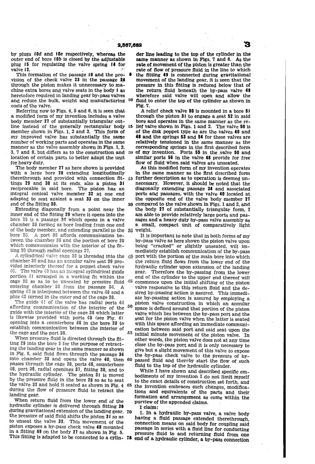
4 Patented Jan. 23, ,367,682 UNITED TATE PATENT OFFICE This invention relates to aircraft landing gear by-pass valves of the type shown in United tates Letters Patent No. 2,267,284, issued December 23, 1941, to C. B. Livers, for controlling the flow of hydraulic fluid in the landing gear actuating cyl inders and circuits so as to prevent evacuation of the upper end of the cylinders and cavitation of the pump and pressure lines during the low ering of the landing gear. The primary object of the present invention is to provide a valve of the character described which embodies improvements over similar valves in that it is simplified as to the construction and arrangement of the ports, passages and various parts and elements thereof, consists of fewer Working parts, is reduced as to weight, may be made at a lower cost, requires less servicing and parts replacement over longer periods of use, and is more efficient and reliable as to performance. An inportant object of my invention is to pro vide a by-pass valve of the character described Which is constructed, arranged and operated to prevent hydraulic locking of the piston valve thereof and consequent failure of the device to by-pass fluid from one end of the cylinder to the other, this objection being encountered with by pass Valves heretofore used, wherein the piston Yalve must be given a considerable movement to open the by-pass port and wherein a cavity pro ducing a vacuum is formed in the piston-valve bore before the piston is moved sufficiently to. open the by-passport. With the foregoing objects in view, together with such other objects and advantages as may subsequently appear, the invention resides in the parts 2nd in the combination, construction and 3rrangement of parts hereinafter described and claimed, and illustrated by way of example in the accorinpanying drawings, in which: Fig. i is a ectional view of a by-pass valve embodying my invention; Fig. 2 is a fragmentary sectional view showing the valve as it would appear when by-passing fluid ifrom one end of a hydraulic cylinder to the other; Fig. 3 is a vertical sectional view taken on the line 3-3 of Fig. 1; Fig. 4 is a sectional view of a modified form of my invention; Fig. 5 is a fragmentary sectional view of the modified valve shown in Fig. 4 as it would appear when by-passing fluid from one end of the cylin der to the other; Fig. 6 is a vertical sectional view taken on the line 6-6 of Fig. 5; LANDING GEAR BY-PA WALVE Ottmar A. Kehle, Van Nuys, Calif., assignor to Adel Precision Products Corp., a corporation of California, Application April 9, 1943, erial No. 482,469 7 Claims. (C ) Fig. 7 is a schematic view of a hydraulic sys O tem for actuating landing gear showing my im proved by-pass valve as it would appear when the landing gear is being extended and indicating how the fluid is by-passed from the bottom to the top of the cylinder; Fig. 8 is a schematic view similar to Fig. 7 but showing the by-pass valve as it would appear during retraction of the landing gear and the manner of the flow of pressure fluid when the gear is retracted. Referring to the drawings more specifically, and particularly to the schematic illustrations in Figs. 7 and 8, it is seen that a by-pass valve A embodying my invention is connected in one of the two cylinder lines B and C (for example line B) leading from a 4-way control valve D to a hydraulic cylinder E for actuating the landing gear F of an airplane. Line G leads from the hydraulic pump (not shown) to the control valve O. While a return line H leads from aid valve to the reservoir (not shown). A by-pass line J is connected with the valve and the cylinder line C leading to the top of the cylinder so that when the landing gear is extended the bye-pa valve A will be automatically operated to the position shown in Fig. 7 to by-pass fluid from the lower end of the cylinder to the upper end thereof. When the 4-way valve D is operated to retract the landing gear, the pressure fluid flows through the by-pass valve to the lower end of the cylinder as shown in Fig. 8. It should be noted that inasmuch as the ex tension of the landing gear is largely effected by force of gravity, the piston of the cylinder expels the fluid from the lower end of the cylinder faster than the pump can supply pressure fluid to the upper end of the cylinder, but with my by-pass valve arranged in the circuit as shown in Fig. and 8 the fluid from the lower end of the cylinder is by-passed to the upper end of the cylinder, thereby preventing evacuation of the cylinder and any objectionable operation, or Op eration failure which would obviously attend such a disproportionate flow of fluid. In addition to by-passing fluid as aforesaid, the valve A acts to direct fluid from the lower end of the cylinder through the 4-way valve D into the return line H when the pressure of the operating fluid above the piston in the cylinder E. exceeds the pressure of the fluid discharging from the lower end of the cylinder as is the case when the gravitational movement of the landing gear ceases and the pressure fluid operates the cylinder to move the landing gear into its com

5 2 pletely extended position where it becomes mes chanically locked in a manner well known to those skilled in the art, but not here shown. Reference is now had to Figs., 2 and 3, where in the valve A is shown as including an elongated body member having a bore 2 extending lon gitudinally therethrough. At one end of this bore is a connection fitting 3 screwed into a threaded enlargement 4 for connection of a sec tion of the cylinder line B therewith, while at the other end of the bore a similar fitting 5 is screwed into a threaded enlargement 6 to pro vide for the connection thereto of the other ec tion of the cylinder line B which leads to the lower end of the cylinder as shown in Fig. 7. A piston valve 7 having a working fit in the bore 2 is provided at one end with an integral conical valve member 8 adapted to seat against an annular eat 9 of maller diameter than the piston proper and formed on the inner end of : the fitting 5. When pressure fluid is directed through the fitting 3 into the bore 2 for retracting the landing gear, the piston valve is shifted by the pressure fluid so that the valve end 8 seats on the seat 9, moving from position shown in Figs. 2 and 7 into position shown in Fig 1 and 8. When thus shifted the piston uncovers a pas age 0 which opens into one end of the bore 2 and leads through the body to the other end of said bore, so that pressure fluid by-passes the then seated piston valve and will flow out through the fitting 5 to the lower end of the cylinder E. In this connection it is seen that the fitting 5 has radial ports if affording communication be tween the passage 0 and the bore through the fitting 5, or generally speaking, a connection be tween the bore 2 and passage 0. As the piston valve 7 proper, apart from the valve member 8 thereon, has a greater diameter than the seat 9, it is apparent that the pressure fluid will hold the piston valve seated while the passage 0 is open for delivery of pressure fluid to the lower end of the cylinder. A check valve 2 of the disk type is provided in the passage 0 adjacent the end thereof opening into the bore. near the fitting 3, said valve seating against a seat 3 in a direction toward the bore 2 so that when the passage 0 is uncovered by the piston valve, as shown in Figs. 1 and 8, the pressure fluid will open the valve against the action of the valve pring 4. This spring is engaged at its ends with an adjustable screw plug f4' and the valve 2 and is tensioned so that the valve will be unseated by the normal pump pressure for actuating the cylinder E. Q When the landing gear is unlatched, in a man ner not here shown, preparatory to its extension, the 4-way valve being set as shown in Fig. 7, so that pressure fluid will flow through the line C to the top of cylinder E, the landing gear will gravitate as indicated in Fig. 7 toward its ex tended position and force the fluid from the lower end of the cylinder E at a greater rate than that of the flow of operating fluid entering the top of the cylinder from the pump. When the land ing gear begins its descent, the piston 7 is closed as shown in Fig. 8, but as soon as the return fluid commences to flow from the lower end of the cyl inder through line B and fitting 5, the piston 7 will be shifted so as to unseat the valve member 8 thereon and will assume the position shown in Fig. 7, whereby fluid will flow through the by pa line J, thence through line C to the top of the cylinder so that the proper volume of fluid a,367,682 will be maintained above the piston during the extension of the landing gear. When the piston is moved to unseat the valve 8 as shown in Fig. 7, it opens a port 5 leading from the bore 2 adjacent the valve seat 9, into a nipple 6 formed on the body member. crewed into this nipple is a tubular fitting 7 to which is coupled a connection fitting 8 con necting the by-pass line J to the cylinder line C. () In the fitting is a valve seat 9 for a spring loaded by-pass check valve 20 of the disk type which seats toward the nipple. Inasmuch as the pressure of the return fluid from the cylinder dur ing the gravitational extension of the landing gear is greater than that of the pressure fluid (plus the force of the spring 2) operative to seat the valve 20 due to the greater rate of egress than ingress of fluid relative to said cylinder, the valve 20 will be opened to allow the by-passing of the fluid from the lower to the upper end of the cylinder as hereinbefore pointed out. As soon as the gravitational movement of the landing gear ceases, as takes place before the movement of the gear into fully extended position in which it becomes automatically latched and held, the pressure of the return fluid becomes less than that of the pressure fluid above the valve 20 and in the upper end of the cylinder E, where upon the valve 20 is pressure seated and the pis ton in the cylinder E is moved to thrust the land ing gear into finally extended position and latch it in such position. During this operation the fluid returned from the lower end of the cylinder Einto the bore 2 builds up a pressure in aid bore 3 5 until a relief check valve 22 of the ball type con trolling a passage 23 through the piston 7, is forced open and the return fluid then passes through the piston passage 23, bore 2, fitting 3, and back to the reservoir (not shown). A pring having a tension adjusting means 25 is set to hold the valve 22 seated while the pressure of the fluid returning during gravitational move ment of the landing gear, is greater than the pump operating pressure against the upper side () 5 s (Bt) ( of the piston and the valve 20. For this reason the valve 20 will be unseated during gravitational in ovement of the landing gear into extended po ition while the relief valve 22 remains seated. However, when the pressure of the operating fluid in line C and the upper end of the cylinder ex ceeds that of the return fluid, following gravita tional movement of the landing gear, this higher pressure plus the force of the pring 2 holds the waive 20 seated while the return fluid pressure builds up to a pressure sufficient to open the re lief valve 22 in the piston. should be noted that the conical valve mem ber 8 on the piston 7, and the valve seat 9 are arranged o that the annular pace formed in the bore 2 around the valve member 8 when the latter is being seated, opens into the port 5 leading to the valve 20 thereby preventing the trapping of fluid in the bore between the piston 7 and valve seat 9. It should be noted that passage O is formed by making a bore Oa longitudinal from one end of the body member to parallel the bore 2 and which terminates adjacent but spaced from the opposite end of the body member, then making bores Ob and Oc from one side of the body member so as to intersect the bore Oa and ex tend at right angles thereto, to points of com munication with the bore 2 near the ends of the latter. The Outer ends of bore Oa and Oc are closed
6

7 4. on said body for coupling said passage with a sec ond fluid line for conducting pressure fluid to and returning fluid from the other end of said cylinder, a by-pass check valve means arranged to seat and close said by-pass connection re sponsive to pressure fluid in said second fluid line and to unseat and open said by-pass con nection when the fluid returned from aid one end of the cylinder to said passage reaches a pressure greater than the pressure of the fluid seating said check valve means, said body hav ing a bore therein communicating at its ends with said passage, a piston valve arranged in said bore to move into position to shut off communication between said by-pass connection and aid pas sage responsive to the passage of pressure fluid through said passage for delivery to said one end of the cylinder, and to move into position afford ing communication of said by-pass connection with said passage responsive to the return of fluid from said one end of the cylinder to aid passage, a check valve means arranged to close said passage at a point between the points of communication of said bore with the passage re sponsive to the flow of return fluid into said pas sage from said one end of the cylinder, aid pis ton valve having a relief port extended there through for conducting return fluid from said passage through said bore and out of aid valve body while the check valve in said passage is closed; and a relief check valve arranged in aid port to be seated and close said port while the pressure of return fluid in the passage is greater than the pressure of the operating fluid holding the by-pass check valve seated, and to be opened by pressure of the return fluid when the pressure of the return fluid is less than that of the operat ing fluid seating said by-pass check valve, there being in said bore a valve seat of smaller diam eter than said piston valve, the latter having a frusto-conical end engageable with said valve eat. 2. In a hydraulic by-pass valve, a valve body of substantially triangular outline having a bore extended therethrough, connection means on said body for coupling the bore in series with a fluid line for conducting pressure fluid to and return ing fluid from one end of a hydraulic cylinder, a passage in said body having its ends arranged to open into the end portions of said bore, a check valve intermediate the ends of aid passage ar ranged to open incident to the flow of pressure fluid into aid passage from said bore and to close responsive to the flow of return fluid into aid passage from aid bore, a by-pa Connec tion on said body having communication with said bore, and adapted for coupling aid bore with another fluid line through which pressure fluid is directed to and fluid is returned from the other end of the hydraulic cylinder, whereby re turn fluid may be directed from aid one end of the cylinder to the other end of the cylinder; a by-pa check valve arranged to be seated to close said by-pass connection, by pressure of fluid in the fluid line coupled to said by-pass connec tion and to be unseated and open said by-pass Connection. When the pressure of return fluid in said bore exceeds the pressure of the fluid in the fluid line coupled to said by-pass connection; a valve seat in aid bore at a point between the ends thereof; a piston Valve in said bore operat ing responsive to the introduction of pressure fluid into aid bore for delivery to said one end of the cylinder through said passage, to engage said valve seat and shut of communication of the 2,367, ) (5 s bore with said by-pass connection and by-pass check valve, and to be unseated and open said bore to communication with said by-pass connec tion when return fluid is delivered to said bore from said cylinder; a port in said piston valve affording the passage of return fluid through said bore and away from said body, while the check valve in said passage is closed; and a check valve controlling said port so that the port will be open only when the pressure of the fluid seating the by-pass check valve is greater than the pressure of the return fluid, said passage extending oblique ly relative to said bore and having in it a valve chamber in which the first named check valve is mounted. 3. In a hydraulic by-pass valve, a valve body having a bore extended therethrough, connection means on said body for coupling the bore in eries with a fluid line for conducting pressure fluid to and returning fluid from one end of a hydraulic cylinder, a passage in said body having its ends arranged to open into the end portions of aid bore, a check valve intermediate the ends of aid passage arranged to open incident to the flow of pressure fuid into said passage from aid bore and to close responsive to the flow of return fluid into said passage from aid bore, a by-pass Con nection on said body having communication with said bore, and adapted for coupling aid bore with another fluid line through which pressure fluid is directed to and fluid is returned from the other end of the hydraulic cylinder, whereby re turn fluid may be directed from said one end of the cylinder to the other end of the cylinder; a by-pass check valve arranged to be seated to close said by-pass connection by pressure of fluid in the fluid line coupled to said by-pass connec tion and to be unseated and open aid by-pa connection when the pressure of return fluid in said bore exceeds the pressure of the fluid in the fluid line coupled to said by-pass connection; a valve seat in said bore at a point between the ends thereof; a piston valve in aid bore Operat ing responsive to the introduction of pressure fluid into said bore for delivery to said one end of the cylinder through said passage, to engage said valve seat and shut off communication of the bore with said by-pass connection and by pass check valve, and to be unseated and Open said bore to communication with said by-pass connection when return fluid is delivered to said bore from said cylinder; a port in aid piston valve affording the passage of return fluid through said bore and away from aid body, while the check valve in said passage is closed; and a check valve controlling aid port O that the port Will be open only when the pressure of the fluid seating the by-pass check valve is greater than the pressure of the return fluid, said valve seat being of a maller diameter than aid bore, and the piston valve having a frusto-conical end to seat on said valve seat, said port opening through the center of said frusto-conical end. 4. In a hydraulic by-pass valve for controlling the flow of fluid in a hydraulic cylinder for air craft landing gear which responds to gravita tional forces while being extended, a valve body having a bore therein, means affording the con nection of one end of aid bore with a fluid line for conducting fluid to and from said bore, means for connecting the other end of said bore with a cylinder line for conducting fluid from said bore to the lower end of the cylinder for retract ing the landing gear, through which cylinder line return fluid flows to said bore upon the extension

8 of the landing gear, a by-pass port opening into said bore, a by-pass connection affording the con nection of said port with a second cylinder line for conducting fluid to and returning it from the upper end of said cylinder, a by-pass check valve in said connection arranged to close aid port responsive to pressure of fluid derived in aid connection from the econd cylinder line and to open said port responsive to the pressure of re turn fluid in aid bore and port as derived upon gravitational extension of aid landing gear, whereby fluid returned from the lower end of the cylinder is by-passed through said bore, aid port and said connection to the upper end of the cyl inder, a pressure fluid passage in said body hav ing its ends opening into aid bore adjacent the ends of the latter for conducting pressure fluid through the body for delivery to the lower end of the hydraulic cylinder to retract the landing gear, a check valve in aid passage opening re ponsive to pressure fluid delivered to said bore through first named end of said bore and closing responsive to return fluid from the cylinder con nected end of the bore, a valve seat in aid bore between the by-pass port and the point where the pressure passage discharges pressure fluid into aid bore, a piston valve mounted in said bore to engage aid seat and shut off communi cation between said by-pass port and the cylin der Connected end of aid bore responsive to pressure fluid delivered to said bore through said One end of the bore and operating to open said cylinder connected end of the bore to communi cation with aid seat responsive to the pressure of fluid returned to the bore during gravitational extension of the landing gear; said, piston, said seat and aid by-pass port being constructed and arranged. o that a portion of the bore urround ing the piston affords communication of the port up to the point where the piston engages its seat Whereby upon initial unseating movement of said piston the cylinder connected end of the bore is immediately brought into direct, communication with aid port, a relief passage within the body affording the discharge of return fluid from the cylinder connected end of the bore through the other end of the bore; and a normally closed check valve in said relief passage set to open only when the eating pressure on the by-pass check valve exceeds that of the return fluid pressure in the cylinder connected end of the bore, 5. In a hydraulic by-pass valve for controlling the flow of fluid in a hydraulic cylinder for air craft landing gear which responds to gravita tional forces while being extended, a valve body having a bore therein, means affording the con nection of One end of said bore with a fluid line for conducting fluid to and from said bore, means for connecting the other end of said bore with a cylinder line for conducting fluid from said bore to the lower end of the cylinder for retract ing the landing gear, through which cylinder line return fluid flows to said bore upon the ex tension of the landing gear, a by-passport open ing into aid bore, a by-pass connection affording the connection of said port with a second cylin der line for conducting fluid to and returning it from the upper end of said cylinder, a by-pass check valve in said connection arranged to close aid port responsive to pressure fluid derived in said connection from the second cylinder line and to open aid port responsive to the pressure of re turn fiuid in aid bore and port as derived upon gravitational extension of said landing gear, whereby fluid returned from the lower end of the 2,867, s cylinder is by-passed through said bore, said port and said connection to the upper end of the cyl inder; a pressure fluid passage in said body hav ing its ends opening into said bore adjacent the ends of the latter for conducting pressure fluid through the body for delivery to the lower end of the hydraulic cylinder to retract the landing gear, a check valve in said passage opening responsive to pressure fluid delivered to said bore through first named end of said bore and closing respon ive to return fluid from the cylinder connected end of the bore, a valve seat in said bore between the by-pass port and the point where the pres ure paage discharges pressure fluid into aid bore, a piston valve mounted in said bore to en gage aid eat and shut off communication be tween said by-pass port and the cylinder con nected end of aid bore responsive to pressure fluid delivered to said bore through said one end of the bore and operating to open said cylinder connected end of the bore to communication with aid seat responsive to the pressure fluid returned to the bore during gravitational extension of the landing gear; aid piston, said seat and said by pa port being so constructed and arranged that a portion of the bore urrounding the piston af fords communication of the port up to the point where the piston engages its seat whereby upon initial unseating movement of said piston the cyl inder connected end of the bore is immediately brought into direct communication with said port, a relief passage within the body affording the discharge of return fluid from the cylinder connected end of the bore through the other end of the bore; and a normally closed check valve in aid relief passage et to open only when the eating pressure on the by-pass check valve ex ceeds that of the return fluid pressure in the cylinder connected end of the bore, said relief paage extending axially through the piston and being exposed through the valve seat to the cyl inder connected end of the bore when the piston Valve is eated. 6. The invention as set forth in claim 2 wherein the piston valve has a conical end portion to en gage the valve seat therefor and the portion of the bore between the seated portion of said coni cal end portion and aid by-pass connection is Open. Whereby upon initial movement of the pis ton away from its seat the return fluid pressure has immediate access to said by-pass check valve. 7. In a hydraulic by-pass valve for controlling the flow of fluid in a hydraulic cylinder for air Craft landing gear which responds to gravita tional forces while being extended, a valve body having a bore therein, means affording the con nection of one end of said bore with a fluid line for conducting fluid to and from said bore, means for connecting the other end of said bore with a cylinder line for conducting fluid from said bore to the lower end of the cylinder for retracting the landing gear, through which cylinder line re turn fluid flows to said bore during extension of the landing gear, a by-passport opening into said bore, a econd cylinder line having a by-pass con nection affording the connection of said port with aid bore for conducting fluid to and returning it from the upper end of said cylinder, a by-pass check Valve in aid connection arranged to close aid port responsive to pressure of fluid derived in aid connection from the second cylinder line and to open aid port responsive to the pressure of return fluid in aid bore and port as derived upon gravitational extension of saidlanding gear, whereby fluid returned from the lower end of
9 6 2,367,682 the cylinder is by-passed through said bore, said port and said connection to the upper end of the cylinder, a pressure fluid passage in said body having its ends opening into said bore adjacent. the ends of the latter for conducting pressure 5 fluid through the body for delivery to the lower end of the hydraulic cylinder to retract the land ing gear, a check valve in aid passage Opening responsive to pressure fluid delivered to said bore through first named end of said bore and closing responsive to return fluid from the cylinder con nected end of the bore, a valve seat in said bore between the by-pass port and the point where the pressure passage discharges pressure fluid into that end portion of said bore, which is con nected with the lower end of the aforesaid hy. draulic cylinder, a piston valve-mounted in said bore to engage aid eat and shut off communi cation between said by-passport and the cylinder connected end of said bore responsive to pressure so 10 fluid delivered to said bore through said one end of the bore and operating to open said cylinder connected end of the bore to communication with said seat responsive to the pressure of fluid re turned to the bore during gravitational extension of the landing gear; said piston, said seat and said by-pass port being constructed and arranged o that upon initial unseating movement of said piston the cylinder connected end of the bore is immediately brought into direct communication with said port, a relief passage within the body affording the discharge of return fluid from the cylinder connected end of the bore through the other end of the bore; and a normally closed check valve in said relief passage set to open only when the eating pressure on the by-pass check valve exceeds that of the return fluid pressure in the cylinder connected end of the bore. OMAR A. EEHL.E.
2,376,968. May 29, F. M. JONES TWO-CYCLE GAS ENGINE. 2 Sheets-Sheet li. Filed Dec. 26, 1942 FIG, vucinto FREDERICK M. JONES.
 May 29, 1945. F. M. JONES Filed Dec. 26, 1942 2 Sheets-Sheet li 7. FIG, 8??? ///?/ ( vucinto FREDERICK M. JONES ( Cltt May 29, 1945. F. M. JONES Filed Dec. 26, 1942 2. Sheets-Sheet 2 48 aa FG. 2 35 21
Feb. 9, ,168,853 R. PRINCE HYDRAULIC CYLINEDER DEVICE. Filed Oct. 8, Sheets-Sheet l ~~~~ INVENTOR. 162/12e2 aga/2.
 Feb. 9, 1965 Filed Oct. 8, 1962 R. PRINCE HYDRAULIC CYLINEDER DEVICE 3,168,853 2 Sheets-Sheet l ~~~~ INVENTOR. 162/12e2 aga/2. BY Feb. 9, 1965 R. PRINCE 3,168,853 HYDRAULIC CYLINDER DEVICE Filed Oct. 8,
?zzzzzzzzzzzzzzzzzzzzzzzzzzzzzzzzzzzzzzz -! zzzzzzzzz,zzzzzzzzz. sssss?sssssss,! PATENTED JULY 21, PNEU MATIC SUSPENSION MEANS, J. H.
 J. H. CLARK, PNEU MATIC SUSPENSION MEANS, APPLICATION FILED JUNE 24 1907. PATENTED JULY 21, 1908. sssss?sssssss,! S?zzzzzzzzzzzzzZZZZZZZZZZZZZZZZZZZZZZZZZZ -! SN 22 222 zzzzzzzzz,zzzzzzzzz INVENTOR ZVetezrzes...
2,407,010 ADAPTER HEAD FOR WELLS. Filed Aug. 8, Sheets-Sheet. Lester C. Hudson
 Sept. 3, 1946. L. C. HUDSON 2,407,010 ADAPTER HEAD FOR WELLS Filed Aug. 8, 1945 2 Sheets-Sheet Lester C. Hudson Sept. 3, 1946. 2 407,010 L. C. HUDSON ADAPTER HEAD FOR WELLS Filled Aug. 8, 1945 2. Sheets-Sheet
June 19, 1962 v. P. DoNNER 3,039,212 HYDRAULIC APRON AND EJECTOR GATE MECHANISM FOR SCRAPERS
 June 19, 1962 v. P. DoNNER HYDRAULIC APRON AND EJECTOR GATE MECHANISM FOR SCRAPERS Filed July ll, 1960. Sheets-Sheet l June 19, 1962 3,039,212 V. P. DONNER HYDRAULIC APRON AND EJECTOR GATE MECHANISM FOR
2,042,301. VALVE SEAT FOR AIR BLAST WALVES Filled May 3, Sheets-Sheet. By??????r /7
 May 26, 1936. G. FOX VALVE SEAT FOR AIR BLAST WALVES Filled May 3, 1934 2 Sheets-Sheet 11 -W + By??????r /7 May 26, 1936. G. FOX WALWE SEAT FOR AIR BLAST WALWES Filed May 3, 1934 %22&zzzzzzzzº2zzzzzzzzzzzzzzzzzzzzzzzzzzzzzzzzzzzzzzzzzzzzzzzzzzzzzzzzz
Dec. 30, 1969 T. FRAYER 3,486,801. BRAKE PRESSURE CONTROL VALVE Filed Aug. 1, Sheets-Sheet I9 f 39 43
 Dec. 30, 1969 T. FRAYER BRAKE PRESSURE COTROL VALVE Filed Aug. 1, 1968 2 Sheets-Sheet 1 SKID DETECTOR 5 38 37 5 45.42 4 7 44 46 I9 f 39 43 36 W 35 ( 34 8 52 48 (7.5 / 7s 4o ii, SSS Y e Š K S : FIG. 2 IVETOR.
& 9. Š. Aerary 4. Morazzzzzok. May 19, : 1,538,208. INVENTORS INTERNAL COMBUSTION MOTOR. atz Aazzzz c1. A1arclaezzf H. A. NORDWICK E. A.
 May 19, 1925. :. H. A. NORDWICK E. A. INTERNAL COMBUSTION MOTOR Filed Oct, l9, 1923 2. Sheets-Sheet. & 9. Š W S A. SSS S S R Sr. SS SS INVENTORS Aerary 4. Morazzzzzok atz Aazzzz c1. A1arclaezzf. ar a ATTORNEY
PATENTED JULY 17, No , I. N. MOORE, DUPLEX STEAM ENGINE, A PLICATION FILED APR, 7, 1904, 3 SHEETS-SHEET 1. SY SY.
 No. 825 924, I. N. MOORE, DUPLEX STEAM ENGINE, A PLICATION FILED APR, 7, 1904, PATENTED JULY 17, a 1906. 3 SHEETS-SHEET 1. 4 Witnesses: SY SY -? ZA No. 825,924, PATENTED JULY 17, 1906.? I, N, MOORE, DUPLEX
United States Patent (19) Kubik
 Kubik") United States Patent (19) Kubik 11 Patent Number: ) Date of Patent: May, 1989 54 SELF-REGULATED HYDRAULIC CONTROL SYSTEM 76 Inventor: Philip A. Kubik, 27 Lochridge, Bloomfield Hills, Mich. 48013 21 Appl.
United States Patent (19) Kubik 11 Patent Number: ) Date of Patent: May, 1989 54 SELF-REGULATED HYDRAULIC CONTROL SYSTEM 76 Inventor: Philip A. Kubik, 27 Lochridge, Bloomfield Hills, Mich. 48013 21 Appl.
Dec. 10, ,415,169 M. NADDELL HYDRAULIC CYLINDER. Filed June Sheets-Sheet l INVENTOR. 42aze/Zaaa24/ 59ée A77OAAWAY
 Dec. 10, 1968 Filed June 10 1966 M. NADDELL HYDRAULIC CYLINDER 3 Sheets-Sheet l BY INVENTOR. 4aze/Zaaa4/ 59ée A77OAAWAY Dec. 10, 1968 M. NADDEL HYDRAULIC CYLINDER Filled June 10, 1966 3. Sheets-Sheet NS
March 16, ,173,402 W. D. CASSEL AUTOMATIC CATTLE SPRAYER. Filed Aug. 26, Sheets-Sheet l /WA70? WALTER D, CASSEL.
 March 16, 1965 Filed Aug. 26, 1963 W. D. CASSEL 3. Sheets-Sheet l /WA70? WALTER D, CASSEL a 4-4 12, A7/0PAY March 16, 1965 W. D. CASSEL Filed Aug. 26, 1963 3. Sheets-Sheet 2 CN March 16, 1965 W. D. CASSEL
Dec. 3, G. H. LELAND 1,737,595 ELECTRIC MOTOR W/a Av/2Ap. 2-2, 3 3 6AOAGAA. l. E/A/VD. 4772A/VAy
 Dec. 3, 1929. G. H. LELAND 1,737,595 ELECTRIC MOTOR. Filed Sept. 20, 1926 2 Sheets-Sheet - - - - - - 9. -- W/a Av/2Ap. 3 3 6AOAGAA. l. E/A/VD. 2-2, 4772A/VAy Dec. 3, 1929. G. H. LELAND 1,737,595 ELECTRIC
2 121,002. June 21, R. C. BAKER CEMENT RETAINER AND BRIDGE PLUG FOR WELL CASINGS 2 Sheets-Sheet l ATTORNEY
 June 21, 1938. 2 121,002 R. C. BAKER CEMENT RETAINER AND BRIDGE PLUG FOR WELL CASINGS 2 Sheets-Sheet l BY ATTORNEY June 21, 1938. R. C. EBAKER 2,121,002 CEMENT RETAINER AND BRIDGE PLUG FOR WELL CASINGS
UNITED STATES PATENT OFFICE
 UNITED STATES PATENT OFFICE FRANKLIN A. ERRINGTON, OF NEW YORK, N. Y. PRO PE ER REVERS E G EAR IO 3O 35 40 45 SPECIFICATION forming part of Letters Patent No. 644,508, dated February 27, 1900. Application
APPLICATION FLED JAN, 27, 1917, 1253,982, Patented Jan, 15, 1918,
 H, V, KRBY, FUSHNG MECHANISM, APPLICATION FLED JAN, 27, 1917, 1253,982, Patented Jan, 15, 1918, 2. SHEES-SHEET, H, V, KRBY, FUSHING MECHANISM, APPLICATION FLED JAN, 27, 1917, 253,982, Patented Jan. 15,
United States Patent (19) 11) 4,444,223 Maldavs 45) Apr. 24, 1984
 11) 4,444,223 Maldavs 45) Apr. 24, 1984") United States Patent (19) 11) 4,444,223 Maldavs 45) Apr. 24, 1984 54) QUICK DISCONNECT COUPLING 56) References Cited U.S. PATENT DOCUMENTS 75) Inventor: Ojars Maldavs, Lincoln, Nebr. 3,039,794 6/1962 Cenzo...
United States Patent (19) 11) 4,444,223 Maldavs 45) Apr. 24, 1984 54) QUICK DISCONNECT COUPLING 56) References Cited U.S. PATENT DOCUMENTS 75) Inventor: Ojars Maldavs, Lincoln, Nebr. 3,039,794 6/1962 Cenzo...
"(2.4% May 4, 1954 C. A. GUSTAFSON 2,677,202. Filed April 3, l95l AND EJECTOR OF EARTH-MOWING SCRAPERS 3. Sheets-Sheet CAR. A.
 May 4, 1954 C. A. GUSTAFSON 2,677,202 HYDRAULIC ACTUATOR FOR OPERATING THE APRON Filed April 3, l95l AND EJECTOR OF EARTH-MOWING SCRAPERS 3. Sheets-Sheet INVENTOR, CAR. A. G2/S7AASOM/ "(2.4%. 2.-- ATTORME,
Feb. 23, F.. rayfield 1,846,656 SINGLE STAGE COMPRESSOR. Fied Nov. 15, Sheets-Sheet. l. -1. s s. AederacA /ARa%e?ad. 27 (6.
 Feb. 23, 1932. F.. rayfield 1,846,656 Fied Nov. 15, 1929 3. Sheets-Sheet. l. -1. s s AederacA /ARa%e?ad 27 (6.44% as near-sell -ress Feb. 23, 1932. F. J. RAYFIELD 1846,656 Filed Nov. 15, 1929 5. Sheets-Sheet
,62?925% HLIAI ELE ) w W/////7M //, aeoww. June 17, VI/27/702A 21, 1967 N SON S. Sheet 2 of 2 W. H. BROWN WARIABLE FLOW TURBOFAN ENGINE
 w W/////7M //, aeoww. June 17, VI/27/702A 21, 1967 N SON S. Sheet 2 of 2 W. H. BROWN WARIABLE FLOW TURBOFAN ENGINE") June 17, 1969 Filed Dec. 21, 1967 W. H. BROWN WARIABLE FLOW TURBOFAN ENGINE 3 449 914 Sheet 2 of 2 N SON S RT,62?925% HLIAI ELE ) 77VI/27/702A w W/////7M //, aeoww C2 United States Patent Office Patented
June 17, 1969 Filed Dec. 21, 1967 W. H. BROWN WARIABLE FLOW TURBOFAN ENGINE 3 449 914 Sheet 2 of 2 N SON S RT,62?925% HLIAI ELE ) 77VI/27/702A w W/////7M //, aeoww C2 United States Patent Office Patented
Mizilt 22A. United States Patent (19) 4,721,175. Jan. 26, Patent Number: 45 Date of Patent: 54 RACK AND PINION STEERING GEAR
 4,721,175. Jan. 26, Patent Number: 45 Date of Patent: 54 RACK AND PINION STEERING GEAR") United States Patent (19) Butler 54 RACK AND PINION STEERING GEAR ASSEMBLY (75) Inventor: Philip M. Butler, Mudgley, Great Britain 73) Assignee: TRW Cam Gears Limited, Clevedon, England 21 Appl. No.: 933,782
United States Patent (19) Butler 54 RACK AND PINION STEERING GEAR ASSEMBLY (75) Inventor: Philip M. Butler, Mudgley, Great Britain 73) Assignee: TRW Cam Gears Limited, Clevedon, England 21 Appl. No.: 933,782
W. Hope. 15 Claims, 5 Drawing Figs. (52) U.S. Cl , 5ll int. Cl... F16k 43100, F16k 5/14
 U.S. Cl , 5ll int. Cl... F16k 43100, F16k 5/14") United States Patent (72 inventor Clyde H. Chronister 4 Kings Row, Rte. 14, Houston, Tex. 77040 (2) Appl. No. 823,103 (22 Filed May 8, 1969 45 Patented Jan. 26, 197i. 54) GATE WALVE 15 Claims, 5 Drawing
United States Patent (72 inventor Clyde H. Chronister 4 Kings Row, Rte. 14, Houston, Tex. 77040 (2) Appl. No. 823,103 (22 Filed May 8, 1969 45 Patented Jan. 26, 197i. 54) GATE WALVE 15 Claims, 5 Drawing
April 2, 1968 O. BE TRAM 3,375,595 SINGLE BUCKET EXCAVATOR 12 INVENTOR. OS M A NO BE L T R A N. "I'llur awl ov. 4-wa
 April 2, 1968 O. BE TRAM SINGLE BUCKET EXCAVATOR Filed April 27, 1965 2. Sheets-Sheet 12 INVENTOR. OS M A NO BE L T R A N "I'llur awl ov 4-wa April 2, 1968 O. BELTRAM SINGLE EUCKET EXCAVATOR Filed April
(12) Patent Application Publication (10) Pub. No.: US 2007/ A1
 Patent Application Publication (10) Pub. No.: US 2007/ A1") US 20070257638A1 (19) United States (12) Patent Application Publication (10) Pub. No.: US 2007/0257638A1 Amend et al. (43) Pub. Date: Nov. 8, 2007 (54) TWIST LOCK BATTERY INTERFACE FOR (52) U.S. Cl....
US 20070257638A1 (19) United States (12) Patent Application Publication (10) Pub. No.: US 2007/0257638A1 Amend et al. (43) Pub. Date: Nov. 8, 2007 (54) TWIST LOCK BATTERY INTERFACE FOR (52) U.S. Cl....
22-y 2 24, 7. -l- az. Z é - Jan. 26, 1971 D. F. webster 3,557,549 TURBOCHARGER SYSTEM FOR INTERNAL COMBUSTION ENGINE. is is a ST.
 Jan. 26, 1971 D. F. webster 3,557,549 23 9 -a- 3. Sheets-Sheet El -l- Area Arena S is is a ST BY DONALD F. WEBSTER Y az. Z 224 724.0 2é - 22-y 2 24, 7 Jan. 26, 1971 D. F. WEBSTER 3,557,549 3 Sheets-Sheet
J, S, ROGERS, PADOCK, APPLICATION FILED MAY 15, 1915, 1,153,405. Patented Sept, 14, 1915, 2 SHEETS-S HEET i. 3-vi-ucvtot 21, 6)) 7/4-ee-d
) 7/4-ee-d") J, S, ROGERS, PADOCK, APPLICATION FILED MAY 15, 1915, 1,153,405. Patented Sept, 14, 1915, 2 SHEETS-S HEET i. 6)) 21, 7/4-ee-d 3-vi-ucvtot 1,153,405. J, S, ROGERS, PADOCK, APPLICAON FED MAY 5, 1915, Patented
J, S, ROGERS, PADOCK, APPLICATION FILED MAY 15, 1915, 1,153,405. Patented Sept, 14, 1915, 2 SHEETS-S HEET i. 6)) 21, 7/4-ee-d 3-vi-ucvtot 1,153,405. J, S, ROGERS, PADOCK, APPLICAON FED MAY 5, 1915, Patented
Jan. 14, ,421,236. Filed June 22, E, U, MOYER ATTORNEYS LINKAGE FOR AN EJECTOR TYPE BUCKET, LOADER
 Jan. 14, 1969 Filed June 22, E, U, MOYER LINKAGE FOR AN EJECTOR TYPE BUCKET, LOADER ATTORNEYS Jan. 14, 1969 E. U. MOYER LINKAGE FOR AN EJECTOR TYPE BUCKET, LOADER Filed June 22, 1967 Sheet a of 2. INVENTOR
No.sse,*****<<<<<<<<<<<<
 June 3, 1936. F. J. WOLFF MIXING WALWE Filed Dec. 9, N SY 1933,04,308. Sheets-Sheet l No.sse,*****
3.s. isit. United States Patent (19) Momotet al. 2 Šg. 11 Patent Number: 4,709,634 (45) Date of Patent: Dec. 1, Zxx (54) (75) (73)
 Momotet al. 2 Šg. 11 Patent Number: 4,709,634 (45) Date of Patent: Dec. 1, Zxx (54) (75) (73)") United States Patent (19) Momotet al. (54) (75) (73) (1) () 51 5 (58) 56) PLATE CYLNDER REGISTER CONTROL Inventors: Stanley Momot, La Grange; William G. Hannon, Westchester, both of Ill. Assignee: Rockwell
United States Patent (19) Momotet al. (54) (75) (73) (1) () 51 5 (58) 56) PLATE CYLNDER REGISTER CONTROL Inventors: Stanley Momot, La Grange; William G. Hannon, Westchester, both of Ill. Assignee: Rockwell
F, L, BARBER & C. S. WAT 0 N, CAR TRUCK, APPLICATION FILED APR. 28, 9. Patented June 12, , SHEETS-SHEET 2. ssna
 1229,398. F, L, BARBER & C. S. WAT 0 N, CAR TRUCK, APPLICATION FILED APR. 28, 9. Patented June 12, 1917. 2. SHEETS-SHEET 2. ssna it worris FEFFRS (c. soro ir G. vwasi trw«. * OM. 2 C I.5 35 UNITED STATES
Az Z 1.357,665. Azzee/2Z27. Patented Nov. 2, y 24-cee?, A-6. vy
 1.7,665. P. H. WATKNS, (UM SHEETING AND SCORING MACHINE, APPLICATION FILED MAY 28, 1920. Patented Nov. 2, 1920. 2 SHEETS-SHEET 1. Az Z B Azzee/2Z27 A 27/62//l/2éAz72s. y 24-cee?, A-6. vy-4----. P, H, WAT
Aug. 10, ,595,232 W. S. HARLEY ELECTRIC SWITCH. HParié a. % - se. Zezezza77. Za2z/2a22 J/622ce/ 72/ ( clo-c-3 v (J.,
 Aug. 10, 1926. 1,595,232 W. S. HARLEY ELECTRIC SWITCH Filed April 13, 1922 2. Sheets-Sheet f t Fre ls HParié a % - se Sh Zezezza77 Za2z/2a22 J/622ce/ 72/ ( clo-c-3 v (J., Aug. 10, 1926. 1,595,232 W. S.
3,114,326 12/1963 Yaindi... 62/55 3,206,110 9/1965 Waibel /567 3,260,217 7/1966 Thresher /569
 United States Patent (19) Yaindl 54 RECIPROCATING PLUNGER PUMP WITH IMPROVED LIQUID END WALVE ASSEMBLY 75 Inventor: 73) Assignee: Charles Yaindl, Harrison, N.J. Worthington Pump, Inc., Mountainside, N.J.
10-sea /2 72/7e/ * 22%,962a. PATENTED OCT, l0, l905, No. 801,754.
 No. 801,754. PATENTED OCT, l0, l905, J. A., WOGEL. FLUSHING APPARATUS FOR WATER CLOSETS APPLICATION FILED APR, l, 1905, 2. SHEETS-SHEET. 10-sea /2 72/7e/ * 22%,962a elitotivat No. 801,754, PATENTED OCT,
No. 801,373. PATENTED 00T, 10, J. E. GEARHART, ROTARY ENGINE, APPLIOATION FILED AUG, 2, HEETs-SHEET. Z2562/2ZZZ Aa27/2(272, inventor
 No. 801,373. PATENTED 00T, 10, 1905. J. E. GEARHART, ROTARY ENGINE, APPLIOATION FILED AUG, 2, 1905. 28HEETs-SHEET. Witnesses -á22, séze Z2562/2ZZZ Aa27/2(272, inventor by Attorneys No. 80l.,373, PATENTED
United States Patent (19) Parquet et al.
 Parquet et al.") United States Patent (19) Parquet et al. 54 HYDRAULIC SKID STEERING CONTROL SYSTEM 75) Inventors: Donald J. Parquet; Carl O. Pedersen, both of Burlington, Iowa (73) Assignee: J. I. Case Company, Racine,
United States Patent (19) Parquet et al. 54 HYDRAULIC SKID STEERING CONTROL SYSTEM 75) Inventors: Donald J. Parquet; Carl O. Pedersen, both of Burlington, Iowa (73) Assignee: J. I. Case Company, Racine,
April 5, G, E, SWANSON 2,113,007 CYLINDER LOCK. NS: S.S.S.S.S Né EEE SS W. a. <SNSSSSSSSS/fde. is E( 4 NN. p7 NSN NNNN N&zo 76 v7 /6 2/23 / NS
 April, 1938. G, E, SWANSON CYLINDER LOCK Filed May 17, 1937 2. Sheets-Sheet 1 SNNNN ÉSEŠEŠ V 443 SY NS: S.S.S.S.S Né EEE SS W. a.
&Z2Zd? S-4, <jit Vald (d.
 Dec. 22, 1964 P. WALACH HYDRAULIC DOOR CLOSER Filed Jan. 25, 1962 2 Sheets-Sheet 1 77 2 INVENTOR H 2 Abazz/ Z2/2C/2- &Z2Zd? S-4, <jit Vald (d. (22%s Dec. 22, 1964 Filed Jan. 25, 1962 P. WAACH HYDRAULIC
(12) Patent Application Publication (10) Pub. No.: US 2008/ A1
 Patent Application Publication (10) Pub. No.: US 2008/ A1") (19) United States US 20080000052A1 (12) Patent Application Publication (10) Pub. No.: US 2008/0000052 A1 Hong et al. (43) Pub. Date: Jan. 3, 2008 (54) REFRIGERATOR (75) Inventors: Dae Jin Hong, Jangseong-gun
(19) United States US 20080000052A1 (12) Patent Application Publication (10) Pub. No.: US 2008/0000052 A1 Hong et al. (43) Pub. Date: Jan. 3, 2008 (54) REFRIGERATOR (75) Inventors: Dae Jin Hong, Jangseong-gun
United States Patent (19) Koitabashi
 Koitabashi") United States Patent (19) Koitabashi 54 75 (73) 1 (51) (5) (58 56) ELECTROMAGNETIC CLUTCH WITH AN IMPROVED MAGNETC ROTATABLE MEMBER Inventor: Takatoshi Koitabashi, Annaka, Japan Assignee: Sanden Corporation,
United States Patent (19) Koitabashi 54 75 (73) 1 (51) (5) (58 56) ELECTROMAGNETIC CLUTCH WITH AN IMPROVED MAGNETC ROTATABLE MEMBER Inventor: Takatoshi Koitabashi, Annaka, Japan Assignee: Sanden Corporation,
WAMI ENSI eae, EsNetII E A2. 2.Er. a ( A2 HEAE M - 15 / a7. Ells.S. 7 a M8 7 Ž22/ A. A. MEDDOCK 27 BY SWAZZZZ
 Nov. 24, 1953 A. A. MEDDOCK AUTOMATIC QUICK DISCONNECT COUPLING Filed Dec. 28, 1948 m 2 Sheets-Sheet M - 15 /7 #3 2.Er. HEAE SWAZZZZ Fiil, WAMI FM if EsNetII 44 MA v 26 387 a7 a 26-47 (72.247 A2 7 a ENSI
April 22, 1969 R. R. MYERS 3,439,368 SWIMMING POOL CLEANER. Filled Jan. 3, //V/AA/7OA. aaaaya /7 a.a5. As / Al-Aza 47.4% r-77%---a A77 oawals
 April 22, 1969 R. R. MYERS 3,439,368 Filled Jan. 3, SWIMMING POOL CLEANER //V/AA/7OA aaaaya /7 a.a5 As / Al-Aza 47.4% r-77%---a A77 oawals April 22, 1969 R. R. MYERS 3,439,368 SWIMMING FOOL CLEANER '-
Nov. 19, 1963 W. J. LEE 3,111,246 SHIRT FOLDING MACHINE Filed May ll, Sheets-Sheet 1 INVENTOR. by A-4,5- anzawy &Arafat
 Nov. 19, 1963 W. J. LEE SHIRT FOLDING MACHINE Filed May ll, 1960 4 Sheets-Sheet 1 Wing A. Lee INVENTOR. by A-4,5- anzawy &Arafat Nov. 19, 1963 W. J. EE SHIRT FOLDING MACHINE Filed May 11, 1960 4. Sheets-Sheet
-24 Af SA-/2 =SE É 242
 Aug. 31, 196 N. T. GENERAL WARIABLE SPEED FRICTIN DRIVE TRANSMISSIN Filed Jan., 1963 A3 A3 A. Zae ow NV -/4 exés A/ // A. NA4/6 4 / A / N // A RN 1. A7, 4% Af as ulee A -4 Af SA-/ =SE É 4 A4 /74 --N NN
(12) Patent Application Publication (10) Pub. No.: US 2014/ A1
 Patent Application Publication (10) Pub. No.: US 2014/ A1") (19) United States US 20140299792A1 (12) Patent Application Publication (10) Pub. No.: US 2014/0299792 A1 Yee et al. (43) Pub. Date: Oct. 9, 2014 (54) SEALING ABOUT A QUARTZ TUBE (52) U.S. Cl. CPC... F2IV31/005
(19) United States US 20140299792A1 (12) Patent Application Publication (10) Pub. No.: US 2014/0299792 A1 Yee et al. (43) Pub. Date: Oct. 9, 2014 (54) SEALING ABOUT A QUARTZ TUBE (52) U.S. Cl. CPC... F2IV31/005
United States Patent (19) Cronk et al.
 Cronk et al.") United States Patent (19) Cronk et al. (S4) LANDING GEAR FOR ULTRALIGHT AIRCRAFT 76) Inventors: David Cronk, 1069 Eucalyptus Ave., Vista, Calif. 92025; Lyle M. Byrum, 1471 Calle Redonda, Escondido, Calif.
United States Patent (19) Cronk et al. (S4) LANDING GEAR FOR ULTRALIGHT AIRCRAFT 76) Inventors: David Cronk, 1069 Eucalyptus Ave., Vista, Calif. 92025; Lyle M. Byrum, 1471 Calle Redonda, Escondido, Calif.
?????????? 24,??: Aug. 12, ulazca S. CoMA/asa BY) J. S. CONNER 2,425,306. Filed April 26, 1945 INVENTOR. 2 Sheets-Sheet l
 J. S. CONNER 2,425,306. Filed April 26, 1945 INVENTOR. 2 Sheets-Sheet l") Aug. 12, 1947. J. S. CONNER RETRACTILE WING AND ANDING GEAR Filed April 26, 1945 2 Sheets-Sheet l INVENTOR. ulazca S. CoMA/asa BY)?????????? 24,??: Aug. 12, 1947, J. S. CONNER RETRACTILE WING AND LANDING
Aug. 12, 1947. J. S. CONNER RETRACTILE WING AND ANDING GEAR Filed April 26, 1945 2 Sheets-Sheet l INVENTOR. ulazca S. CoMA/asa BY)?????????? 24,??: Aug. 12, 1947, J. S. CONNER RETRACTILE WING AND LANDING
7/22. Z62/ lazy f/2zzzaz. e- re-er- 7tee /7Zetas. Aug. 28, 1962 H. R. KILLIAN 3,050,781
 Aug. 28, 1962 H. R. KILLIAN 3,050,781 MOLDED IN PLACE RUBBER SEAT BUTTERFLY WALVE Filed Aug. 28, 1959 5 Sheets-Sheet 1 e- re-er- 7tee 2. Z62/ lazy f/2zzzaz 7/22. 22222/7Zetas Aug. 28, 1962 H. R. KILLIAN
April 3, 1956 J. MONTANA 2,740,484 MOTOR DRIVEN STAIR CLIMBING HAND TRUCK
 April 3, 1956 J. MONTANA 2,740,484 MOTOR DRIVEN STAIR CLIMBING HAND TRUCK Filed Aug. 26, 1950 3. Sheets-Sheet l //WVEW7OA JAMES MOW/AWA April 3, 1956 J. MONTANA 2,740,484 MOTOR DRIVEN STAIR CLIMBING HAND
Sept. 20, 1971 L, A, CHESHER 3,606,112 RETRACTABLE BEVERAGE HOLDER FOR MOTOR WEHICLES. "Ne ) h \ 23. es/fs-s. Fig. 2 E3 2 (2S, Si. N.
 h \ 23. es/fs-s. Fig. 2 E3 2 (2S, Si. N.") Sept. 20, 1971 L, A, CHESHER Filed Jan. 28, 1970 3 Sheets-Sheet Hi (1. s A. 2 Wrze "Ne ) h \ 23 3f he W \, SC-3/ es/fs-s 32 33 Fig. 7 3? Y62 - - a 2 E3 2 (2S, Si Y N. aa 24 - - - - - -9 1-- //W/EW7OA Leonord
Sept. 20, 1971 L, A, CHESHER Filed Jan. 28, 1970 3 Sheets-Sheet Hi (1. s A. 2 Wrze "Ne ) h \ 23 3f he W \, SC-3/ es/fs-s 32 33 Fig. 7 3? Y62 - - a 2 E3 2 (2S, Si Y N. aa 24 - - - - - -9 1-- //W/EW7OA Leonord
Jan. 15, 1957 W. C. MESSICK 2,777,416 FIRE ALARM DEWECE AN35 QSS A. INVENTOR WARD C MESSECK. 6.1%a-4 2. sy/2c. a 77 o Aem at Ys
 Jan. 1, 197 W. C. MESSICK FIRE ALARM DEWECE Filed Nov., 13, l93 2. Sheets-Sheet l 27 AN3 N QSS NS S. S A. INVENTOR WARD C MESSECK BY sy/2c 6.1%a-4 2 a 77 o Aem at Ys Jan. 1, 197 W. C. MESSECK FIRE ALARM
s /5 June 12, 1951 H. E. SPEARS ET AL 2,556,854 7 ZN NSN MAGNETIC COUPLING DRIVE FOR HIGH-PRESSURE Filed Oct 29, Saeets-Sheet 1
 June 12, 191 H. E. SPEARS ET AL MAGNETIC COUPLING DRIVE FOR HIGH-PRESSURE STIRRED REACTORS / Filed Oct 29, 1949 2 Saeets-Sheet 1 N 7 ZN Y N S s / NSN June 12, 191 H. E. SPEARS ET AL MAGNETIC COUPLING DRIVE
34. 2,960,722 AHIL FOR PLASTIC BLISTER FORMING MACHINE ATTONEY. 2. Sheets-Sheet. Filed Jan. 5, m; IITILITILITIVATIII Nuys, lii; CCCCC
 Nov. 22, 19 AUTMATIC WEB INDEXING P. FREEMAN AND CUT-FF APPARATUS 2,9,722 Filed Jan. 5, 19 FR PLASTIC BLISTER FRMING MACHINE 2. Sheets-Sheet t All m; IITILITILITIVATIII Nuys, lii; CCCCC 2 AHIL 34. INVENTR,
*2.4 crewat (totif. I realizo. all estalla-ze. June 2, M. J. POSTER 1,807,752 AUTOMOBILE TIRE INDICATOR OR GAUGE Filed April 8, 1930.
 June 2, 1931. M. J. PSTER 1,7,72 AUTMBILE TIRE INDICATR R GAUGE Filed April 8, 19 2 Sheets-Sheet 1 14 2SSSSSSSSs a2%%n 2 3. seases Élisé 2. 3 S 3 263 E 3aw 3 ES 3 e I realizo 2 all estalla-ze a slue Ig
NNNNN. United States Patent (19) SNS 4,605,269. Aug. 12, 1986 SNNNNN, 11 Patent Number: 45 Date of Patent:
 SNS 4,605,269. Aug. 12, 1986 SNNNNN, 11 Patent Number: 45 Date of Patent:") United States Patent (19) Cohen et al. 54 PRINTED CIRCUIT BOARD HEADER HAVING COAXAL SOCKETS THEREN AND MATABLE COAXAL PLUGHOUSING 75 Inventors: Thomas S. Cohen, Camp Hill; Douglas F. Finan, Harrisburg,
United States Patent (19) Cohen et al. 54 PRINTED CIRCUIT BOARD HEADER HAVING COAXAL SOCKETS THEREN AND MATABLE COAXAL PLUGHOUSING 75 Inventors: Thomas S. Cohen, Camp Hill; Douglas F. Finan, Harrisburg,
Jan. 12, 1960 B, P. GASSNER 2,920,636 CONTROL VALVE. sys z al 2SSR INVENTOR, BEAT R GASSNER a or area (26am A77 ORWAYS
 Jan. 12, 1960 B, P. GASSNER CONTROL VALVE Filed June 20, 1955 3. Sheets-Sheet l' 25623 S 2SSR 22 22 z al SN SN SS S. sys INVENTOR, BEAT R GASSNER a or area (26am A77 ORWAYS Jan. 12, 1960 Filed June 20,
EWSAN. United States Patent (19) 4,696,524. Cloyd. Sep. 29, ROBOT ARM COUPLING APPARATUS Inventor: Assignees:
 4,696,524. Cloyd. Sep. 29, ROBOT ARM COUPLING APPARATUS Inventor: Assignees:") United States Patent (19) Cloyd (54) (75) (73) 21) 22 51) (52) (58) (56) ROBOT ARM COUPLING APPARATUS Inventor: Assignees: William C. Cloyd, Lexington, Ky. Custom Tool & Mfg. Co.; Automation Development
United States Patent (19) Cloyd (54) (75) (73) 21) 22 51) (52) (58) (56) ROBOT ARM COUPLING APPARATUS Inventor: Assignees: William C. Cloyd, Lexington, Ky. Custom Tool & Mfg. Co.; Automation Development
United States Patent (19) Shew
 Shew") United States Patent (19) Shew 54) I75 (73) 21 22) 51 52 (58 (56) DUAL MODE GREASE GUN Inventor: Assignee: Jerry D. Shew, Niles, Ill. Stewart-Warner Corporation, Chicago, Ill. Appl. No.: 729,242 Filed:.
United States Patent (19) Shew 54) I75 (73) 21 22) 51 52 (58 (56) DUAL MODE GREASE GUN Inventor: Assignee: Jerry D. Shew, Niles, Ill. Stewart-Warner Corporation, Chicago, Ill. Appl. No.: 729,242 Filed:.
United States Patent (19) Berthold et al.
 Berthold et al.") United States Patent (19) Berthold et al. (54) AXIAL PISTON MACHINE OF THE SWASHPLATE OR BENTAXS TYPE HAVING SLOT CONTROL AND PRESSURE BALANCING PASSAGES 75 Inventors: Heinz Berthold, Horb; Josef Beck,
United States Patent (19) Berthold et al. (54) AXIAL PISTON MACHINE OF THE SWASHPLATE OR BENTAXS TYPE HAVING SLOT CONTROL AND PRESSURE BALANCING PASSAGES 75 Inventors: Heinz Berthold, Horb; Josef Beck,
United States Patent (19) Miller, Sr.
 Miller, Sr.") United States Patent (19) Miller, Sr. 11 Patent Number: 5,056,448 (45) Date of Patent: Oct. 15, 1991 (54) (76. (21) (22) 51 (52) (58) PVC BOAT Inventor: Terry L. Miller, Sr., P.O. Box 162, Afton, Okla.
United States Patent (19) Miller, Sr. 11 Patent Number: 5,056,448 (45) Date of Patent: Oct. 15, 1991 (54) (76. (21) (22) 51 (52) (58) PVC BOAT Inventor: Terry L. Miller, Sr., P.O. Box 162, Afton, Okla.
(12) Patent Application Publication (10) Pub. No.: US 2017/ A1
 Patent Application Publication (10) Pub. No.: US 2017/ A1") (19) United States (12) Patent Application Publication (10) Pub. No.: US 2017/0102085 A1 Smith, III et al. US 201701 02085A1 (43) Pub. Date: Apr. 13, 2017 (54) (71) (72) (21) (22) (60) SUBSEA BOP CONTROL
(19) United States (12) Patent Application Publication (10) Pub. No.: US 2017/0102085 A1 Smith, III et al. US 201701 02085A1 (43) Pub. Date: Apr. 13, 2017 (54) (71) (72) (21) (22) (60) SUBSEA BOP CONTROL
(12) United States Patent
 United States Patent") USOO7654162B2 (12) United States Patent Braaten (54) DEVICE FOR INSTALLATION OF A PROBE AND PROBEACCOMMODATING ARRANGEMENT (75) Inventor: Nils A. Braaten, Trondheim (NO) (73) Assignee: Roxar ASA, Stavanger
USOO7654162B2 (12) United States Patent Braaten (54) DEVICE FOR INSTALLATION OF A PROBE AND PROBEACCOMMODATING ARRANGEMENT (75) Inventor: Nils A. Braaten, Trondheim (NO) (73) Assignee: Roxar ASA, Stavanger
(12) Patent Application Publication (10) Pub. No.: US 2015/ A1. Ogawa (43) Pub. Date: Jul. 2, KYa 7 e. a 21
 Patent Application Publication (10) Pub. No.: US 2015/ A1. Ogawa (43) Pub. Date: Jul. 2, KYa 7 e. a 21") (19) United States US 2015O184681A1 (12) Patent Application Publication (10) Pub. No.: US 2015/0184681 A1 Ogawa (43) Pub. Date: (54) ACTUATOR (52) U.S. Cl. CPC... F15B 15/149 (2013.01); F 15B 21/14 (71)
(19) United States US 2015O184681A1 (12) Patent Application Publication (10) Pub. No.: US 2015/0184681 A1 Ogawa (43) Pub. Date: (54) ACTUATOR (52) U.S. Cl. CPC... F15B 15/149 (2013.01); F 15B 21/14 (71)
United States Patent (19) Dasa
 Dasa") United States Patent (19) Dasa 54 MULTIPLE CONFIGURATION MODEL AIRCRAFT 76) Inventor: Madhava Dasa, P.O. Box 461, Kula, Hi. 96790-0461 (21) Appl. No.: 103,954 22 Filed: Oct. 2, 1987 51) Int. Cl.... A63H
United States Patent (19) Dasa 54 MULTIPLE CONFIGURATION MODEL AIRCRAFT 76) Inventor: Madhava Dasa, P.O. Box 461, Kula, Hi. 96790-0461 (21) Appl. No.: 103,954 22 Filed: Oct. 2, 1987 51) Int. Cl.... A63H
USOO582O2OOA United States Patent (19) 11 Patent Number: 5,820,200 Zubillaga et al. (45) Date of Patent: Oct. 13, 1998
 11 Patent Number: 5,820,200 Zubillaga et al. (45) Date of Patent: Oct. 13, 1998") USOO582O2OOA United States Patent (19) 11 Patent Number: Zubillaga et al. (45) Date of Patent: Oct. 13, 1998 54 RETRACTABLE MOTORCYCLE COVERING 4,171,145 10/1979 Pearson, Sr.... 296/78.1 SYSTEM 5,052,738
USOO582O2OOA United States Patent (19) 11 Patent Number: Zubillaga et al. (45) Date of Patent: Oct. 13, 1998 54 RETRACTABLE MOTORCYCLE COVERING 4,171,145 10/1979 Pearson, Sr.... 296/78.1 SYSTEM 5,052,738
April 2, 1968 A. L. NASVYTIs 3,375,739 CONICAL, PLANETARY FRICTION GEAR DRIVE Filed Feb. 17, Sheets-Sheet l N. N S
 April 2, 1968 A. L. NASVYTIs CONICAL, PLANETARY FRICTION GEAR DRIVE Filed Feb. 17, 1966 3 Sheets-Sheet l st SS N. N S A. N S INVENTOR. 167/raas Z. Maszy/7s -3% 1%-1. 72e-este, "4e 71-16tz,ORNEYS April
(12) Patent Application Publication (10) Pub. No.: US 2006/ A1. CoSSette et al. (43) Pub. Date: Jan. 5, 2006
 Patent Application Publication (10) Pub. No.: US 2006/ A1. CoSSette et al. (43) Pub. Date: Jan. 5, 2006") US 2006OOOO349A1 (19) United States (12) Patent Application Publication (10) Pub. No.: US 2006/0000349 A1 CoSSette et al. (43) Pub. Date: Jan. 5, 2006 (54) REGENERATION MANIFOLD FOR A (22) Filed: Jun.
US 2006OOOO349A1 (19) United States (12) Patent Application Publication (10) Pub. No.: US 2006/0000349 A1 CoSSette et al. (43) Pub. Date: Jan. 5, 2006 (54) REGENERATION MANIFOLD FOR A (22) Filed: Jun.
Feb. 14, 1967 R. B. WENGER 3,304,094 CLIMBING WHEEL CHAIR A/C. Z. 5 is INVENTOR. a/caezo as a 7/gate, 57 d. 2. XO aoz. 1277aatavays.
 Feb. 14, 1967 R. B. WENGER CLIMBING WHEEL CHAIR Filed Dec. 22, 1964 3. Sheets-Sheet A/C. Z. is INVENTOR. a/caezo as a 7/gate, BY 7 d. 2. XO-4-2. 32427 aoz 1277aatavays. Feb. 14, 1967 R. B. WENGER CLIMBING
(12) Patent Application Publication (10) Pub. No.: US 2014/ A1
 Patent Application Publication (10) Pub. No.: US 2014/ A1") (19) United States US 2014O124322A1 (12) Patent Application Publication (10) Pub. No.: US 2014/0124322 A1 Cimatti (43) Pub. Date: May 8, 2014 (54) NORMALLY CLOSED AUTOMOTIVE (52) U.S. Cl. CLUTCH WITH HYDRAULC
(19) United States US 2014O124322A1 (12) Patent Application Publication (10) Pub. No.: US 2014/0124322 A1 Cimatti (43) Pub. Date: May 8, 2014 (54) NORMALLY CLOSED AUTOMOTIVE (52) U.S. Cl. CLUTCH WITH HYDRAULC
BY 4. earea Carence A. Aroppe/ INVENTOR. Afg. 5
 July 5, 1966 C. L. ROPPEL 3,259,343 CONTROL APPARATUS FOR WERTICAL TAKE-OFF AIRCRAFT Filed Sept. 23, l964 2. Sheets-Sheet l Afg. 5 S MX Year aa. 2 s E 2 s 1. w se s XX Se N W S. Carence A. Aroppe/ INVENTOR
uranayasa NNN (226er? Z /zcz-az77a 7-z Dec. 1, 1959 A. F., HICKMAN 2,915,306 RUBBER TORSION SPRING ZZZZZZZZA SSXSSSSSSSSSSS 50 \... "...
 Dec. 1, 1959 A. F., HICKMAN 2,915,306 RUBBER TORSION SPRING Filed June 24, 1955 2 Sheets-Sheet l NYaNNNNNNNaa %2 uranayasa NNN IX ZZZZZZZZA \........ "......: S SSXSSSSSSSSSSS 50 12 42 INVENTOR. (226er?
March 27, 1956 T. A. DOURDEVILLE 2,739,366
 ROLL-DRIVING MECHANISM FOR A NAPPING MACHINE Filed Oct. 26, 193 4. Sheets-Sheet l K i Fi 9. ée INVENTOR, THEODORE A DOURDEVILLE, 4-y ATTY. ROLL-DRIWING MECHANISM FOR A NAPPING MACHINE Filed Oct. 26, l93
2,835,125 LATCHING MECHANISM. 3. Sheets-Sheet 2 NII N bel2. gy:jip 72UL. ali?i. 2%. s: 2. t. NU 2z, Z z? Azózzee/
 May, 1958 H. F. GEORGE LATCHING MECHANISM 3. Sheets-Sheet 2 2 NII-376 2N bel2 (3 Sl Ig gy:jip 72UL 2 707 ali?i 2 2%. s: 2. t NU 2z, Z.427 272 z? Azózzee/ May, 1958 H. F. GEORGE LATCHING MECHANISM Filed
Victor J. Marolda Rov Manstan NOTICE
 Se rial Number 682.878 Filing Date 24 June 1997 Inventor Victor J. Marolda Rov Manstan NOTICE The above identified patent application is available for licensing. Requests for information should be addressed
United States Patent (19) Kline et al.
 Kline et al.") United States Patent (19) Kline et al. 11 Patent Number: 45 Date of Patent: Jul. 3, 1990 54 BRAKING SYSTEMAND BREAK-AWAY BRAKNG SYSTEM 76 Inventors: Wayne K. Kline, R.D. 1, Box 340, Turbotville, Pa. 17772;
United States Patent (19) Kline et al. 11 Patent Number: 45 Date of Patent: Jul. 3, 1990 54 BRAKING SYSTEMAND BREAK-AWAY BRAKNG SYSTEM 76 Inventors: Wayne K. Kline, R.D. 1, Box 340, Turbotville, Pa. 17772;
June 6, ,987,128 W. KREG SOIL, DAMMING IMPLEMENT. Filed June ll, Sheets-Sheet. Werner Arieg INVENTOR. &&. ~~~~
 June 6, 1961 Filed June ll, 197 W. KREG SOIL, DAMMING IMPLEMENT 2 Sheets-Sheet ~~~~ Werner Arieg INVENTOR. &&. June 6, 1961 Filed June ill, 197 W. KREG SOIL, DAMMING IMPLEMENT 2 Sheets-Sheet 2 Werner Arieg
45a Eleft-16A. United States Patent (19) Suzuki et al. Na2 Š23X 32A. 11 Patent Number: 5,427,361. siz Sé 44
 Suzuki et al. Na2 Š23X 32A. 11 Patent Number: 5,427,361. siz Sé 44") United States Patent (19) Suzuki et al. 54 VIBRATION ISOLATING APPARATUS 75 Inventors: Yasuhiro Suzuki; Hiroshi Kojima, both of Yokohama, Japan 73 Assignees: Nissan Motor Co., Ltd., Yokohama; Bridgestone
United States Patent (19) Suzuki et al. 54 VIBRATION ISOLATING APPARATUS 75 Inventors: Yasuhiro Suzuki; Hiroshi Kojima, both of Yokohama, Japan 73 Assignees: Nissan Motor Co., Ltd., Yokohama; Bridgestone
United States Patent (19. Doi et al.
 United States Patent (19. Doi et al. 11 ) Patent Number: Date of Patent: Nov. 7, 1989 54 SCREW COMPRESSOR 75) Inventors: Motomichi Doi, Katsuta; Minetoshi - Izushi, Shimizu; Kazuhiko Kawaike, Katsuta;
Phillips (45) Date of Patent: Jun. 10, (54) TRIPLE CLUTCH MULTI-SPEED (58) Field of Classification Search
 Date of Patent: Jun. 10, (54) TRIPLE CLUTCH MULTI-SPEED (58) Field of Classification Search") (12) United States Patent US008747274B2 () Patent No.: Phillips () Date of Patent: Jun., 2014 (54) TRIPLE CLUTCH MULTI-SPEED (58) Field of Classification Search TRANSMISSION USPC... 74/3, 331; 475/207
(12) United States Patent US008747274B2 () Patent No.: Phillips () Date of Patent: Jun., 2014 (54) TRIPLE CLUTCH MULTI-SPEED (58) Field of Classification Search TRANSMISSION USPC... 74/3, 331; 475/207
November Jeffrey A. Wong Thomas L. Daugherty Gordon D. Huntzberry NOTICE
 Serial No. Filing Date Inventor 753.055 19 November 1996 Jeffrey A. Wong Thomas L. Daugherty Gordon D. Huntzberry NOTICE The above identified patent application is available for licensing. Requests for
(12) United States Patent
 United States Patent") USOO9296.196B2 (12) United States Patent Castagna et al. (54) PRINTING UNITS FORVARIABLE-FORMAT OFFSET PRINTING PRESSES (71) Applicant: OMET S.r.l., Lecco (IT) (72) Inventors: Stefano Castagna, Civate
USOO9296.196B2 (12) United States Patent Castagna et al. (54) PRINTING UNITS FORVARIABLE-FORMAT OFFSET PRINTING PRESSES (71) Applicant: OMET S.r.l., Lecco (IT) (72) Inventors: Stefano Castagna, Civate
HHRH. United States Patent (19) Lissaman et al. (11) Patent Number: 5,082,079 (45) Date of Patent: Jan. 21, 1992 (51) (54) (75) (73)
 Lissaman et al. (11) Patent Number: 5,082,079 (45) Date of Patent: Jan. 21, 1992 (51) (54) (75) (73)") United States Patent (19) Lissaman et al. HHRH US00082079A (11) Patent Number:,082,079 (4) Date of Patent: Jan. 21, 1992 (4) (7) (73) 21) 22 (1) (2) (8) PASSIVELY STABLE HOVERNG SYSTEM Inventors: Assignee:
United States Patent (19) Lissaman et al. HHRH US00082079A (11) Patent Number:,082,079 (4) Date of Patent: Jan. 21, 1992 (4) (7) (73) 21) 22 (1) (2) (8) PASSIVELY STABLE HOVERNG SYSTEM Inventors: Assignee:
United States Patent (19) Cannon et al.
 Cannon et al.") United States Patent (19) Cannon et al. 54) (75) (73) 21) 22) (51 (52) (58) (56) NTERCHANGEABLE WHOLE-BODY AND NOSE-ONLY EXPOSURE SYSTEM Inventors: William C. Cannon; Rudolph T. Allemann, both of Richland,
United States Patent (19) Cannon et al. 54) (75) (73) 21) 22) (51 (52) (58) (56) NTERCHANGEABLE WHOLE-BODY AND NOSE-ONLY EXPOSURE SYSTEM Inventors: William C. Cannon; Rudolph T. Allemann, both of Richland,
III. United States Patent (19) Barefoot 5,507,368. Apr. 16, Patent Number: (45) Date of Patent:
 Barefoot 5,507,368. Apr. 16, Patent Number: (45) Date of Patent:") United States Patent (19) Barefoot 54 RAILWAY CAR TRUCK MOUNTED BRAKE ASSEMBLY WITH MULTIPLE PSTON AIR CYLNDER 75 Inventor: Richard Barefoot, Greenville, S.C. 73) Assignee: Ellcon National, Inc., Greenville,
United States Patent (19) Barefoot 54 RAILWAY CAR TRUCK MOUNTED BRAKE ASSEMBLY WITH MULTIPLE PSTON AIR CYLNDER 75 Inventor: Richard Barefoot, Greenville, S.C. 73) Assignee: Ellcon National, Inc., Greenville,
Oct. 8, 1968 F. MELLON 3,404,927 BATTERY DISPENSER. Filed April 17, Sheets-Sheet. 2 CE. 2t c. el-n. e are. Iraverator, 7 e44 %-4-4, t/s.
 Oct. 8, 1968 F. MELLON 3,4,927 BATTERY DISPENSER Filed April 17, 1967 2 Sheets-Sheet. i 3. el-n s e are 2 CE. 2t c 32 N Iran le Iraverator, Mezziorz, 7 e44 %-4-4, t/s. Oct. 8, 1968 Filed April 17, 1967
3 23S Sé. -Né 33% (12) United States Patent US 6,742,409 B2. Jun. 1, (45) Date of Patent: (10) Patent No.: 6B M 2 O. (51) Int. Cl...
 United States Patent US 6,742,409 B2. Jun. 1, (45) Date of Patent: (10) Patent No.: 6B M 2 O. (51) Int. Cl...") (12) United States Patent Blanchard USOO6742409B2 (10) Patent No.: (45) Date of Patent: Jun. 1, 2004 (54) DEVICE FORTRANSMISSION BETWEEN A PRIMARY MOTOR SHAFT AND AN OUTPUT SHAFT AND LAWN MOWER PROVIDED
(12) United States Patent Blanchard USOO6742409B2 (10) Patent No.: (45) Date of Patent: Jun. 1, 2004 (54) DEVICE FORTRANSMISSION BETWEEN A PRIMARY MOTOR SHAFT AND AN OUTPUT SHAFT AND LAWN MOWER PROVIDED
(12) United States Patent (10) Patent No.: US 6,643,958 B1
 United States Patent (10) Patent No.: US 6,643,958 B1") USOO6643958B1 (12) United States Patent (10) Patent No.: Krejci (45) Date of Patent: Nov. 11, 2003 (54) SNOW THROWING SHOVEL DEVICE 3,435,545. A 4/1969 Anderson... 37/223 3,512,279 A 5/1970 Benson... 37/244
USOO6643958B1 (12) United States Patent (10) Patent No.: Krejci (45) Date of Patent: Nov. 11, 2003 (54) SNOW THROWING SHOVEL DEVICE 3,435,545. A 4/1969 Anderson... 37/223 3,512,279 A 5/1970 Benson... 37/244
USOOS239155A. United States Patent (19) 11 Patent Number: 5,239,155 Olsson (45) Date of Patent: Aug. 24, 1993
 11 Patent Number: 5,239,155 Olsson (45) Date of Patent: Aug. 24, 1993") O USOOS2391A United States Patent (19) 11 Patent Number: 5,239,1 Olsson (45) Date of Patent: Aug. 24, 1993 (54) MULTIPURPOSE SPOTWELDING GUN replaceable electrode holders with different configura WITH
O USOOS2391A United States Patent (19) 11 Patent Number: 5,239,1 Olsson (45) Date of Patent: Aug. 24, 1993 (54) MULTIPURPOSE SPOTWELDING GUN replaceable electrode holders with different configura WITH
J /> 2-2. ir2 Z), 322. a 62 ZZZZZ/ 3E/ 22.8% SSS 3,388,854. June 18, (SNNNNNNNNNNNNNNNNNNNéNS H. K. OLOFSSON, ETAL NYT ZH
, 322. a 62 ZZZZZ/ 3E/ 22.8% SSS 3,388,854. June 18, (SNNNNNNNNNNNNNNNNNNNéNS H. K. OLOFSSON, ETAL NYT ZH") June 18, 1968 H. K. OLOFSSON, ETAL THRUST BALANCING IN ROARY MACHINES Filed June 25, 1966 4. Sheets-Sheet l (SNNNNNNNNNNNNNNNNNNNéNS AN SN Z), 322 2S2 PS2 4. ZZZZZ/ 3E/ 22.8% SSS 35-Eta S. SAS 323Es 2
June 18, 1968 H. K. OLOFSSON, ETAL THRUST BALANCING IN ROARY MACHINES Filed June 25, 1966 4. Sheets-Sheet l (SNNNNNNNNNNNNNNNNNNNéNS AN SN Z), 322 2S2 PS2 4. ZZZZZ/ 3E/ 22.8% SSS 35-Eta S. SAS 323Es 2
March 23, 1965 J. J. ZAHURANEc 3,174,508 DOUBLE-END SHUT-OFF QUICK-CONNECT TUBE COUPLING. Filed Dec. 7, Z47774.
 March 23, 196 J. J. ZAHURANEc DOUBLE-END SHUT-OFF QUICK-CONNECT TUBE COUPLING Filed Dec. 7, 1962 2Z47774 6 44 42 0 48. NSR 4 VO836) 38/72 ASNNW772, NXYXXWN777 2X2:3, S243As, Eiji 2. s YZ Ari C. SY re.
% Y 2. (12) Patent Application Publication (10) Pub. No.: US 2012/ A1. (19) United States. (43) Pub. Date: Aug. 30, Tanaka et al.
 Patent Application Publication (10) Pub. No.: US 2012/ A1. (19) United States. (43) Pub. Date: Aug. 30, Tanaka et al.") (19) United States (12) Patent Application Publication (10) Pub. No.: US 2012/0216645 A1 Tanaka et al. US 20120216645A1 (43) Pub. Date: Aug. 30, 2012 (54) WORM WHEEL (75) Inventors: Yosuke Tanaka, Saitama
(19) United States (12) Patent Application Publication (10) Pub. No.: US 2012/0216645 A1 Tanaka et al. US 20120216645A1 (43) Pub. Date: Aug. 30, 2012 (54) WORM WHEEL (75) Inventors: Yosuke Tanaka, Saitama
C, J. COLEMAN, ROTARY IMPACT ENGINE, APPLICATION FILED DEC, 3, 1900, RENEWED DEO, 4, 1909, 1,003,708. Patented Sept. 19, PID1.
 C, J. COLEMAN, ROTARY IMPACT ENGINE, APPLICATION FILED DEC, 3, 1900, RENEWED DEO, 4, 1909, 1,003,708. Patented Sept. 19, 1911. WN PID1 sciences 2 SHEETS-SHEET 1. I e St. s. N. S s Q V s N N \ \ ZNSN t
No. 737,796. PATENTED SEPT. 1, 1903, J. A. WOGEL. FLUSHING APPARATUS FOR WATER CLOSETS. APPLICATION FILED SEPT. 17, MODE 2 SEETS-SEET 1.
 No. 737,796. PATENTED SEPT. 1, 1903, J. A. WOGEL. FLUSHING APPARATUS FOR WATER CLOSETS. APPLICATION FILED SEPT. 17, 190. 0 MODE SEETS-SEET 1. t ; 3 - - { 6-? A, z aa - 31 vov tot l/5% -7. Zaeed.s \J 53
"CK-UOW.R. 46AM7 A/6A/ ( aessee. April 29, 1969 F. L. MALONE 3,441,045. Ae665ueez 7 //469 N. Sara - Aea/ya A. MadoMMA AGA. Filed Dec.
 April 29, 1969 F. L. MALONE WARIABLE ORIFICE NOZZLE MIXING EJECTOR Filed Dec. 2, 1966 saysaysay 11 yr. Yova aessee Sara - Ae6ueez A/6A/ (227. 1. Aeass/fea aaya as 7 //469 N 2Awaaaaaaa. state s aawaar AGA
?9? DDLITETTIIN PATENTED JAN. 19, WITNESSES: No. 749,739, 2 SEEETS-SHEET 1. S. LOUNT, TURBINE ENGINE. APPLICATION FILE.D.Nov. 14, 1902.
 No. 749,739, 0 0DE, S. LOUNT, TURBINE ENGINE. APPLICATION FILE.D.Nov. 14, 1902. PATENTED JAN. 19, 1904. 2 SEEETS-SHEET 1. DDLITETTIIN I-III-I-T-T-T-No.v-In-LI, I,II,II,III-I-T-N?9? WITNESSES: ATTORNEY
Dec. 5, L. M., TAYLOR - 2,364,109. 8% Né C. INVENTOR. A Zo Yao /7, 74Yao e ATTORNEY.
 Dec. 5, 1944. L. M., TAYLOR - Filed May 5, 1941 2 Sheets-Sheet NZ % 8% Né C INVENTOR. A Zo Yao /7, 74Yao e ATTORNEY. m Dec. 5, 1944. L. M. TAYLOR CRANKSHAFT AND METHOD FOR MAKING THE SAME Filed May 5,
May 8, ,668,927
 May 8, 1928. J. STUMPF NONCONDENSING STEAM ENGINE Filed Nov. 0, 920 4. Sheets-Sheet A y Ál /Zevorrey. May 8, 1928. J. STUMPF NONCONDENSING STEAM ENGINE Filed Nov. O, 1920 4 Sheets-Sheet 2 D/ May 8, 1928.
(12) Patent Application Publication (10) Pub. No.: US 2010/ A1
 Patent Application Publication (10) Pub. No.: US 2010/ A1") (19) United States US 201001 01228A1 (12) Patent Application Publication (10) Pub. No.: US 2010/0101228A1 Bartosch et al. (43) Pub. Date: (54) (75) (73) (21) (22) (86) (30) DRIVE TRAN COMPRISING AN EXPANDER
(19) United States US 201001 01228A1 (12) Patent Application Publication (10) Pub. No.: US 2010/0101228A1 Bartosch et al. (43) Pub. Date: (54) (75) (73) (21) (22) (86) (30) DRIVE TRAN COMPRISING AN EXPANDER
April 6, Filed Oct, l5, E. PICK. 9 Sheets-Sheet li PLURAL WALWE ACTUATION AND CONTROL
 April 6, 1937. E. PICK PLURAL WALWE ACTUATION AND CONTROL Filed Oct, l5, 1935.? 2 076,321 9 Sheets-Sheet li April 6, 1937. E. P.C.K 2,076,321 PLURAL WALWE ACTUATION AND CONTROL Filed Oct, l5, 1935 9 Sheets-Sheet
D. l. BOHN RADA, ENGINE. Filed Nov. 24, 1950 INVENTOR. Awaza Z. Afoam a/Ways
 D. l. BOHN RADA, ENGINE Filed Nov. 24, 1950 INVENTOR. Awaza Z. Afoam 1777.0a/Ways Patented Jan. 29, 1952 2,584,098 My present invention, relates to radial in combustion engines and more particularly novel