Draper Clinic Handout. FD1 FlexDraper
|
|
|
- Bertha Lucas
- 5 years ago
- Views:
Transcription

1 Draper Clinic Handout FD1 FlexDraper
2 Table of Contents Flex vs Float Break In Service 5 minutes Break In Service 5 hours Break In Service 10 hours Break In Service 50 hours... 6 Maintenance Lubrication Specs Chart Maintenance Hours Maintenance 50 Hours Maintenance 100 Hours Maintenance 250 Hours Maintenance 500 Hours Maintenance 1000 Hours or 3 Years End of Season Knife Maintenance Adjusting Draper Tension Operation Tips Auto Header Height Control Slow Speed Transport / Stabilization Wheel Option New Performance Options Quick Card Draper Clinic Handout - FD1 FlexDraper


3 Flex vs. Float When to Lock and when to Unlock Float refers to the vertical separation (or movement) of the Header from the Float Module. Flex refers to the movement of the 3 piece header frame including the knife. Float Always Lock Float for transport. Always Unlock Float when operating in the field. Handle position (A) is locked for transport. Rotate handle to position (B) for field operation. 2 latches one on either side of Float Module. Flex Always Lock Flex for transport. Can be either locked or unlocked in the field. 2 latches either side. Each wing works independently. Reel moves with cutterbar to maintain close relationship with knife. B Left picture shows handle (A) in wing locked position. Right picture shows handle (B) in wing unlocked position. Draper Clinic Handout - FD1 FlexDraper 3

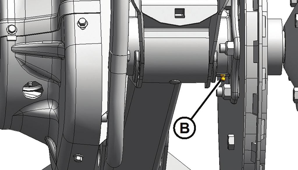
4 Break In Service 5 Minutes Check hydraulic oil level in reservoir (check after first run-up and after hoses have filled with oil). Check the oil level when oil is cold, with the cutterbar just touching the ground and with center-link retracted. FM100 adapters use Single Grade Trans-hydraulic Oil. Normal terrain: Maintain level so lower sight (A) is full, and upper sight (B) is empty. Hilly terrain: Maintain level so lower sight (A) is full, and upper sight (B) is up to one-half filled. Refer to Section 5.4 Hydraulics in the Operators Manual for more information. 5 Hours Check for loose hardware and tighten to required torque. Check knife drive belt tension (check periodically for first 50 hrs). A properly tensioned knife drive belt (C) should deflect mm (15/16 1-1/8 in.) when 133 N (30 lbf) of force is applied at midspan. If the belt tension needs to be adjusted, loosen the two bolts (A) securing the motor assembly and turn the adjuster bolt (B) to move the drive motor until proper tension is set. Refer to Section Knife Drive Belts in the Operators Manual for more information. 4 Draper Clinic Handout - FD1 FlexDraper
 across the drum and cover. Rotate the auger (A) by hand, in forward direction, until it cannot turn anymore. Measure the distance between the two lines (B).")
 is less than 3 mm (0.12 in.), the auger drive chain needs adjusting. Refer to Section 5.7.2 Auger in the Operators Manual for more information.")
5 10 Hours Check auger drive chain tension and knife drive box mounting hardware. Rotate the auger (A) by hand in reverse direction, until it cannot turn anymore. Mark a line (B) across the drum and cover. Rotate the auger (A) by hand, in forward direction, until it cannot turn anymore. Measure the distance between the two lines (B). If the difference (B) is 3 8 mm ( in.), no adjustment is required. If the difference (B) is greater than 8 mm (0.31 in.), the auger drive chain tension needs adjusting. If the difference (B) is less than 3 mm (0.12 in.), the auger drive chain needs adjusting. Refer to Section Auger in the Operators Manual for more information. Check knife drive box mounting bolts. Torque the side bolts (A) first, then torque the bottom bolts (B). Torque all bolts to 271 Nm (200 lbf ft). Refer to Section 5.9 Knife Drive System in the Operators Manual for more information. Draper Clinic Handout - FD1 FlexDraper 5
 and manifold (A). Place a suitably sized container (approximately 1 liter [0.26 gallons]) under the oil drain spout (C) to collect oil runoff.")
6 Break In Service 50 Hours Change float module hydraulic oil filter. Change the oil filter after the first 50 hours of operation, and every 250 hours thereafter. Clean around the mating surfaces of the filter (B) and manifold (A). Place a suitably sized container (approximately 1 liter [0.26 gallons]) under the oil drain spout (C) to collect oil runoff. Remove the spin-off filter (B) and clean the exposed filter port in the manifold (A). Apply a thin film of clean oil to the O-ring provided with the new filter. Turn the new filter into the manifold (A) until the O-ring contacts the mating surface. Tighten the filter an additional 1/2 to 3/4 turn by hand. New filter part number: Refer to Section Hydraulics in the Operators Manual for more information. Change float module gearbox oil. Remove the oil drain plug (A) and the filler plug (C), and allow the oil to drain. Replace the oil drain plug (A) and remove the oil level plug (B). Add SAE 85W-140 (API service class GL-5) oil into the filler plug (C) until it runs out of the oil level hole (B). NOTE: The header drive gearbox holds approximately 2.5 liters (2.6 quarts) of oil. Refer to page 387 Lubrication and Servicing in the Operators Manual for more information. 6 Draper Clinic Handout - FD1 FlexDraper
7 Check float module gearbox chain tension. Remove two bolts and the chain adjusting cover (A). Ensure there is no gasket (B) damage. Remove the retainer plate (C). Tighten bolt (D) to 6.8 Nm (60 lbf in). Refer to Table 5.1 and back off (loosen) bolt (D) based on your gearbox configuration. NOTE: For proper tensioning, the chain should have mm (3/8 9/16 in.) of deflection at its midpoint. Refer to Section Adjusting Gearbox Drive Chain Tension in the Operators Manual for more information. Table 5.1 Adjusting Bolt Tightness on Configured Gearboxes Gearbox Config Gear Ratios Back Off Amounts CLAAS 22/38 sprocket ratio, 74 pitch chain 1 turn Case, New Holland, & AGCO (Challenger, Gleaner, Massey Ferguson) 29/38 sprocket ratio, 78 pitch chain 1 turn John Deere 37/38 sprocket ratio, 80 pitch chain 2-1/2 turns Draper Clinic Handout - FD1 FlexDraper 7
 under the knife drive box to collect the oil. Remove the breather/dipstick (A) and the drain plug (B). Alternate drain plug located on forward side of the box.")
8 Break In Service 50 Hours Continued Change knife drive box lubricant. Raise the header and place a container large enough to hold approximately 2.2 liters (2.3 quarts) under the knife drive box to collect the oil. Remove the breather/dipstick (A) and the drain plug (B). Alternate drain plug located on forward side of the box. Drain the oil and replace the plug. Add 2.2 liters (2.3 quarts) SAE 85W-140 to the knife drive box. Refer to Section 5.9 Knife Drive System in the Operators Manual for more information. Check side draper deck height adjustment. Check that clearance (A) between draper (B) and cutterbar (C) is 0 3mm (0 1/8 in.) If not, rotate connector slat to topside, loosen tension on side draper, grab draper at connector slat and lift up and rearward to remove draper from under cutterbar and expose the deck support. Prop draper up with bar. Measure and note the thickness of the draper belt. Loosen the two lock nuts (D) on the deck support (A) one-half turn only. Tap the deck (A) to lower the deck relative to the deck supports. Tap the deck support beside nuts (D) using a punch to raise the deck relative to the deck supports. Adjust so that measurement (B) is the thickness of the draper plus 1mm as measured previously. Tighten hardware then reinstall and tension draper. Recheck gap to confirm correct adjustment. Refer to Section Header Drapers in the Operators Manual for more information NOTE: Correctly setting side draper deck height will limit the amount of material getting in between the drapers. This should prevent stalling and damage to side drapers. 8 Draper Clinic Handout - FD1 FlexDraper
 performance with 1% max.")
 lithium base As required unless otherwise specified Driveline slip-joints Gear Lubricant SAE 85W-140 API service class GL-5 Knife drive box Main drive gearbox 2.")
9 Maintenance Refer to Section 5.3 Maintenance Requirements in the Operators Manual for more information. Lubrication Specs Chart Lubricant Specifications Description Use Capacities Grease SAE multi-purpose High temperature extreme pressure (EP) performance with 1% max. Molybdenum Disulphide (NLGI Grade 2) lithium base High temperature extreme pressure (EP) performance with 10% max. Molybdenum Disulphide (NLGI Grade 2) lithium base As required unless otherwise specified Driveline slip-joints Gear Lubricant SAE 85W-140 API service class GL-5 Knife drive box Main drive gearbox 2.2 liters (2.3 quarts) 2.5 listers (2.6 quarts) Single grade trans-hydraulic oil recommended brands: Hydraulic Oil Petro-Canada Duratran John Deere Hy-Gard J20C Lubricant trans/hydraulic oil Header drive systems reservoir 75 liters (20 US gallons) Case Hy-Gard J20C AGCO Power Fluid 821 XL Grease Points Draper Clinic Handout - FD1 FlexDraper 9

.")
10 Maintenance Hours 10 hours or daily Check and adjust knife hold-down clips. Hold-down clearance is mm ( in.) Checking knife hold downs daily will keep your knife performing at peak levels, prevent premature wear and ensure a longer life of all your cutting components (ultimately saving you money). 25 hours Grease knife head. 1-2 pumps only. DO NOT OVER GREASE. 10 Draper Clinic Handout - FD1 FlexDraper
")
 D D C C (C)")
")
 (A) Upper Cross")

 Draper Clinic")
11 50 Hours A B B A B (A) Drive roller bearing (B) Idler roller bearing (both sides) D D C C (C) Driveline Slip Joint Optional Attachment (D) Driveline Universal (two places) (A) Upper Cross Auger U-joint and Bearing Upper Cross Auger Bearing (two places) Draper Clinic Handout - FD1 FlexDraper 11
 Auger Drive Chain")

12 Maintenance 100 Hours (A) Float Pivot Right and left (B) Auger Drive Chain (C) Driveline guard (D) Reel Drive Chain 12 Draper Clinic Handout - FD1 FlexDraper
: Between lower hole (D) on")
![dipstick and dipstick bottom edge (E)] (F)](/docs-images/93/113961481/images/13-1.jpg "Upper Cross Auger Bearing (Optional")
 Auger Pivots Draper Clinic")
13 (A) Knife Drive Box [check oil level (B) on dipstick (C): Between lower hole (D) on dipstick and dipstick bottom edge (E)] (F) Upper Cross Auger Bearing (Optional Attachment one place) (G) Main Drive Gearbox Oil Level (A) Auger Pivots Draper Clinic Handout - FD1 FlexDraper 13
 (B) Flex Linkage")
 Frame / Wheel Pivot")
 14 Draper Clinic")
14 Maintenance 250 Hours A B (A) Reel U-joint (one place) (B) Flex Linkage (two places) Both sides Optional Attachment (A) Frame / Wheel Pivot (Front and Rear) both Sides (B) Front Wheel Pivot (one Place) 14 Draper Clinic Handout - FD1 FlexDraper
 Reel Right")
 Wheel Bearings")
 (B) Reel")

15 500 Hours B A D C C (A) Reel Right Bearing (one place) (C) Wheel Bearings (Optional Attachment four places) (B) Reel Center Bearing (one place) (D) Reel Left Bearing (one place) Draper Clinic Handout - FD1 FlexDraper 15
 of 85W 140 (API service class GL-5 oil). Refer to Section 5.")
16 Maintenance 1000 Hours or 3 Years Change hydraulic oil in Float Module reservoir using approximately 75 liters (20 gallons) of Single grade trans-hydraulic oil. Refer to Section 5.4 Hydraulics in the Operators Manual for more information. Change oil in Knife Drive Box using approximately 2.2 liters (2.3 quarts) of 85W 140 (API service class GL-5 oil). Refer to Section 5.9 Knife Drive System in the Operators Manual for more information Change oil in Header Drive Gearbox using approximately 2.5 liters (2.6 quarts) of 85W 140 (API service class GL-5 oil). Refer to Page 387 Lubrication and Servicing in the Operators Manual for more information. 16 Draper Clinic Handout - FD1 FlexDraper
17 End of Season CAUTION Never use gasoline, naphtha, or any volatile material for cleaning purposes. These materials may be toxic and/or flammable. CAUTION Cover cutter bar and knife guards to prevent injury from accidental contact. 1. Clean the header thoroughly. 2. Park the machine for storage in a dry and protected place if possible. If storing outside, always cover the machine with a waterproof canvas or other protective material. NOTE: If storing the machine outside, remove the drapers and store them in a dark, dry place. If not removing the drapers, store the header with the cutter bar lowered so water and snow will not accumulate on the drapers. The weight of water and snow accumulation puts excessive stress on the drapers and header. 3. Lower the header onto blocks to keep the cutter bar off the ground. 4. Lower the reel completely. If stored outside, tie the reel to the frame to prevent rotation caused by the wind. 5. Repaint all worn or chipped painted surfaces to prevent rust. 6. Loosen the drive belts. 7. Lubricate the header thoroughly leaving excess grease on the fittings to keep moisture out of the bearings. 8. Apply grease to exposed threads, cylinder rods, and sliding surfaces of components. 9. Lubricate the knife with SAE30 or equivalent oil. 10. Check for worn components and repair as necessary. 11. Check for broken components and order replacements from your Dealer. Immediate repair of these items will save time and effort at the beginning of next season. 12. Replace or tighten any missing or loose hardware. Draper Clinic Handout - FD1 FlexDraper 17
.")
18 Knife Maintenance Knife Hold Down Adjustment Check hold downs daily (every 10 hours). Hold down clearance is mm ( in). Adjust bolt (B) to achieve clearance at (A). Checking knife hold downs daily will keep your knife performing at peak levels, prevent premature wear and ensure a longer life of all your cutting components (ultimately saving you money). Refer to Section Knife Guards in the Operators Manual for more information. Double Knife Center Guard Adjustment Check clearance daily (every 10 hrs). At guard tip (B) clearance is mm ( in). At rear of guard clearance is mm ( in). With nuts (D) finger tight turn adjuster bolts (E) to achieve clearance, Torque bolts (D) to 72Nn (53 lbf-ft) after adjustments are achieved. Refer to Section Knife Guards in the Operators Manual for more information. 18 Draper Clinic Handout - FD1 FlexDraper
 counterclockwise and white indicator bar (B) will move outboard indicating the draper is being loosened.")
19 Adjusting Draper Tension Side Draper Tension Adjustment Turn bolt (A) clockwise and white indicator bar (B) will move inboard, indicating that the draper is being tightened. Turn bolt (A) counterclockwise and white indicator bar (B) will move outboard indicating the draper is being loosened. When properly tensioned, the white indicator (B) will be halfway across the inboard side of the window. (Left tension adjuster shown). Feed Draper Tension Adjustment Loosen jam nut (A) and turn bolt (B) clockwise to increase center draper tension or counterclockwise to decrease center draper tension. Tension is correct when the white indicator is centered within the indicator window on the spring box (C), however it is permissible to be under-tensioned by 3mm or over-tensioned by 6mm on either or both sides to allow for proper tracking of feed draper. Refer to Section Feed Draper Tension in the Operators Manual Draper Clinic Handout - FD1 FlexDraper 19
20 Operation Tips Adjusting Reel Cam Positions FD1 and D1 series headers feature a 4 position reel cam adjustment (C) on the right end of each reel (Dual reel headers must be adjusted separately for each reel). The factory cam setting is position 2. Use a 19 mm or (¾ ) wrench to rotate pin (A) to release cam disc and adjust cam at (B) to desired setting. Turn pin (A) to engage cam disc lock. Refer to Section Reel Tine Pitch in the Operators Manual for more information. Reel cam position 1 is recommended for straight cut canola where the reel will be pulled back behind the cutter bar and you want minimal reel finger engagement in the crop to limit loss. Reel cam position 2 is for most straight standing cereals and soybeans. Reel cam position 3 is for moderately lodged crop conditions. Reel cam position 4 is for severely lodged crops where the reel will be placed in front of and possibly below the cutter bar. For best lifting action. As the reel tine pitch is increased it also increases the speed of the reel tine tips relative to actual reel speed. Refer to Section Reel Settings and Section Reel Tine Pitch in the Operators Manual for more information. 20 Draper Clinic Handout - FD1 FlexDraper
 (position A on the indicator) for normal cutting conditions or in wet soil conditions to reduce soil build-up at the cutterbar.")
 (position D on the indicator) for lodged crops and crops that pod close to the ground such as lentils or beans. Refer to Section 3.7.")
21 Header Angle Header angle is the relationship between the header (guard tips) and the ground. Set the header angle according to the type and condition of the crop and soil. The shallowest header angle produces the highest stubble height when cutting on the ground; the steepest angle produces the lowest stubble height when cutting on the ground. a. Use shallower settings (A) (position A on the indicator) for normal cutting conditions or in wet soil conditions to reduce soil build-up at the cutterbar. Shallow angle settings also minimize damage to the knife in stony fields. b. Use steeper settings (D) (position D on the indicator) for lodged crops and crops that pod close to the ground such as lentils or beans. Refer to Section Header Angle in the Operators Manual for more information. Reel Height Sensor A reel height sensor located on the RH reel arm is a new standard feature for the FD1 series headers that provides reel height position output; allowing for one touch reel height resume in conjunction with header position. It can be set to lower the reel when lifting the header at the headland to sweep crop off the cutter bar and then return to an in crop height when the header is lowered back to the ground. Not compatible with AGCO combines. Refer to Section 3.8 Auto Header Height Control in the Operators Manual for more information on calibration and setting. Draper Clinic Handout - FD1 FlexDraper 21
22 Auto Header Height Control Setting AHHC MacDon s auto header height control (AHHC) feature works in conjunction with the AHHC option available on most current model combines. A sensor is located in the float indicator box on the FM100 Float Module. This sensor sends a signal to the combine telling it to automatically adjust the feederhouse position to maintain a consistent cutting height and an optimum float (ground pressure) as the header follows ground contours. 1. Disengage header float locks. 2. Ensure that header float is set correctly. Refer to Quick Card. 3. Perform header calibration. 4. Set combine presets through the combine console or control handle. NOTE: Refer to Combine Operator s Manual and Header Operators Manual Section 3.8 Auto Header Height Control for more information on header calibration and settings. The indicator (A) should be at 0 with the header 152 mm (6 in.) off the ground. (If not it may affect the header calibration procedure.). When the header is on the ground, the indicator would be at 1 for low ground pressure, and at 4 for high ground pressure. MacDon recommends using 2 as a starting ground pressure. Ground speed, ground conditions and crop conditions will affect the amount of ground pressure to use. The ideal setting is as light as possible without header bouncing or missing crop. Operating with heavy settings prematurely wears the cutterbar wearplates. 22 Draper Clinic Handout - FD1 FlexDraper
23 Slow Speed Transport / Stabilizer Wheel Option Setting Wheel Height Important: There should only be one point of contact with the ground at any time, either the cutter bar, skid shoes or stabilizer wheels. When cutting on the ground: All stabilizer wheels should be locked into the highest notch with wheels completely off the ground. When cutting off the ground with Slow Speed Transport wheels or Stabilizer wheels: Set header to desired height then position wheels to nearest notch that allows springs to be slightly compressed. IMPORTANT: Continuous operation with excessive spring compression (i.e., load indicator reading greater than 4 or a compressed length (A) less than 295 mm [11-5/8 in.]) can result in damage to the suspension system. Auto header height control when cutting off the ground: To operate with AHHC when cutting off the ground, it might be necessary to lighten float or to add slightly more compression to stabilizer wheel springs so that the header will float upward off of adapter to sense terrain. Ensure that float is unlocked and properly adjusted. Do not over compress springs as this may result in hazard or damage to the shock and spring assembly. Draper Clinic Handout - FD1 FlexDraper 23

24 New Performance Options In Cab Draper Speed Control This option allows the operator the ability to adjust the speed of the side drapers from in the cab of the combine. The kit contains a PWM valve that is installed into the hydraulic manifold and a wire harness that runs into the cab. A suction mounted control panel contains the operator interface. MD #B6387 Dual Auto Header Height This option provides additional auto header height control sensor inputs for the combine lateral tilt circuit allowing the FM100 Float Module to automatically pivot from side to side to follow uneven terrain during operation. The combine requires feeder faceplate tilt option. The kit adds two additional sensors to the float linkage. Not compatible with New Holland 10 volt AHHC system. Not recommended for use on steep hills. MD #B Draper Clinic Handout - FD1 FlexDraper

25 Quick Card FD1 Series Draper Header & FM100 Float Module SETTING HEADER FLOAT AND WING BALANCE Follow these five steps to set the header float and wing balance: IMPORTANT: Read your operator s manual and complete all the setup tasks before setting the header float. Step 1: Preadjustments Complete before adjusting float or wing balance. 1. Park combine on a level surface, and ensure the combine feeder house is level. 2. Ensure the top of the float module is level with the combine axle and the combine tires are inflated equally. 3. Adjust header so cutterbar is mm (6 10 in.) off the ground. 4. Set the header angle hydraulic cylinder to between B and C on indicator (A). 5. Set the reel fore-aft to midposition (5 or 6 on reel arm decal). 6. Lower the reel completely, shut down the combine, and remove key from the combine ignition. 7. Place wing lock spring handles (B) in the locked (upper) position. 8. Place both left and right header float locks in unlocked (lowered) position (C). 9. Set stabilizer/transport wheels (if equipped) to the storage position. Figure 1: Center-Link Figure 2: Wing Lock Spring Handle in Locked Position Figure 3: Float Unlocked Right Side Shown Step 2: Retrieving Torque Wrench from Storage 1. Remove the special torque wrench (A) from its storage position at the right side of the float module frame. Pull in the direction shown to disengage the wrench from its hook. Figure 4: Torque Wrench Storage Location Draper Clinic Handout - FD1 FlexDraper 25
26 Quick Card Step 3: Checking Header Float 1. Place torque wrench (A) onto float lock (B). Note the change in wrench orientation when checking float module s left and right side. 2. Push down on torque wrench (A) to rotate bell crank (C) forward. 3. Continue pushing down on torque wrench until the wrench s indicator (D) reaches a maximum reading and begins to decrease. Note the maximum reading. 4. Repeat above steps for opposite side of float module. 5. Refer to Table 1.1 as a guide for float settings. If the reading is high, the header is heavy. If the reading is low, the header is light. Figure 5: Checking Float Right Side Shown Table 1.1: Float Settings Header Size m (ft.) 9.1 and 10.6 m (30 and 35 ft.) 12.1 and 13.7 m (40 and 45 ft.) Cutting on the Ground Indicator Reading Cutting off the Ground 1-1/2 to 2 2 to 2-1/2 2 to 2-1/2 2-1/2 to 3 IMPORTANT: Torque settings in Table 1.1: Float Settings are recommended header float settings. It may be necessary to set float values outside of these ranges to suit varying crop and field conditions. Figure 6: Checking Float Left Side Shown Step 4: Setting Header Float 1. Before adjusting the float spring adjustment bolts (A), rotate the spring locks (B) by loosening bolts (C). 2. To increase float (decrease header weight), turn both adjustment bolts (A) on the left side clockwise. Repeat adjustment at opposite side. 3. To decrease float (increase header weight), turn left side adjustment bolts (A) counterclockwise. Repeat at opposite side. IMPORTANT: Ensure torque wrench indicator readings are equal on both sides of float module. NOTE: For 12.2 and 13.7 m (40 and 45 ft.) double-knife headers, adjust float as above, then loosen right side float spring bolts two turns. NOTE: If adequate header float cannot be achieved using all the available adjustments, an optional heavy duty spring is available. See your MacDon Dealer or refer to the parts catalog for ordering information. Figure 7: Float Adjustment Bolts Left Side Shown 26 Draper Clinic Handout - FD1 FlexDraper

 to move the bell crank so that the bell crank s lower edge (D) is parallel to the top-link s lower edge (E). b. Ensure pointer (C) is lined up with the top-link (E).")
27 IMPORTANT: Before proceeding, the header float must be set properly. Refer to Step 4: Setting Header Float. Step 5: Check Wing Balance 1. Remove wing balance linkage cover on left side of the float module by removing securing bolt and rotating the cover upwards until the inboard end can be lifted off. 2. Place wing lock spring handles in the unlocked (lower) position. 3. Place torque wrench (A) on bolt (B). 4. Check that pointer (C) is properly positioned as follows: a. Use the torque wrench (A) to move the bell crank so that the bell crank s lower edge (D) is parallel to the top-link s lower edge (E). b. Ensure pointer (C) is lined up with the top-link (E). If necessary, bend the pointer it aligns with bolt hole (J). 5. Move wing upward with torque wrench (A) until the pointer s lower alignment tab (F) lines up with the upper edge of the top-link (E). Refer to Figure 8. Observe the indicator reading (G) on the torque wrench and record it. 6. Move the wing downward with torque wrench (A) until the pointer s upper alignment tab (H) lines up with the lower edge of the top-link (E). Refer to Figure 9. Observe the indicator reading (G) on the torque wrench and record it. 7. Check wing balance on opposite side of header. Figure 8: Wing Balance Linkage, Wings Set too Light Left Side Shown, Right Opposite If the difference between the readings is 0.5 or less, the wing is balanced and adjustment is not required. Lentils Peas Soybeans Delta Rice If the difference between the readings is more than 0.5, the wing is not balanced and adjustment is required. Step 6: Adjust Wing Balance 1. Place torque wrench (A) on bolt (B) on the left side of header. 2. Loosen clevis bolt (C) and jam nut (J). 3. Recheck wing balance. Refer to Step 5: Check Wing Balance. 4. If necessary, make the following adjustments: If the wing is too heavy, turn the clevis adjuster bolt (D) to move clevis (E) outboard (F). If the wing is too light, turn the clevis adjuster bolt (D) to move clevis (E) inboard (G). 5. Adjust clevis (E) position (if necessary) until the difference between torque wrench indicator readings is 0.5 or less. Tighten clevis bolt (C) and jam nut (J). 6. Place wing lock spring handles (H) in the locked (upper) position. If lock doesn t engage, move the wing up and down with the torque wrench (A) until it locks. When locked, there will be some movement in the linkage. Repeat on opposite side of header. 7. If the cutterbar is not straight when wings are in lock mode, then further adjustments are required. Contact your MacDon Dealer. 8. Return the torque wrench (A) to its storage location on the float module frame. Figure 9: Wing Balance Linkage, Wings Set too Heavy Left Side Shown, Right Opposite Figure 10: Wing Balance Linkage Left Side Shown Draper Clinic Handout - FD1 FlexDraper 27


28 Quick Card D1 Series Draper Header & FM100 Float Module 28 Draper Clinic Handout - FD1 FlexDraper


29 Draper Clinic Handout - FD1 FlexDraper 29

30 Quick Card Recommended Fluids and Lubricants Ensure your machine operates at top efficiency by using clean fluids and lubricants only. Use clean containers to handle all fluids and lubricants. Store fluids and lubricants in an area protected from dust, moisture, and other contaminants. Lubricant Specification Description Use Capacities Grease SAE multi-purpose High temperature extreme pressure (EP) performance grease with 1% max Molybdenum Disulphide (NLGI Grade 2) lithium base High temperature extreme pressure (EP) performance grease with 10% max Molybdenum Disulphide (NLGI Grade 2) lithium base As required unless otherwise specified Driveline slip-joints Gear Lubricant SAE 85W-140 API service class GL-5 Knife drive box Main drive gearbox 2.2 liters (2.3 quarts) 2.5 liters (2.6 quarts) Hydraulic Oil Single grade trans-hydraulic oil Recommended brands: Petro-Canada Duratran John Deere Hy-Gard J20C Lubricant trans / hydraulic oil Header drive systems reservoir 75 liters (20 US gallons) Case Hy-Tran Ultraction Break-In Inspections To help avoid major component service or replacement, perform break-in inspections on your machine for the first 50 hours of operation. Refer to your operator s manual for complete break-in inspection and adjustment procedures. Inspection Instance First 5 Minutes 5 Hours 10 Hours Check hydraulic oil level in reservoir (check after first run-up and after the hydraulic hoses have filled with oil). Item Check for loose hardware and tighten to required torque. Check knife drive belts tension (check periodically for the first 50 hours). Check auger drive chain tension. Check knife drive box mounting bolts. Change float module gearbox oil. 50 Hours Change float module hydraulic oil filter. Change knife drive box lubricant. Check gearbox chain tension. Ongoing Maintenance Intervals Refer to the operator s manual for a comprehensive maintenance schedule and record. Log hours of operation, use the maintenance record, and keep copies of your maintenance records. Following the maintenance schedule will increase your machine s life. 30 Draper Clinic Handout - FD1 FlexDraper
31 Notes Draper Clinic Handout - FD1 FlexDraper 31
32 MD-0123D FD1 Draper Clinic Handout - V2
Draper Headers for Combine
 Draper Headers for Combine DRAPER HEADERS FOR COMBINE D1 & FD1 Series Draper Header Performance 2 MacDon Draper Headers for Combine FM100 Float Module The next level of incredible draper performance Most
FD75 FlexDraper Product Training
 Overview MacDon continues to raise the bar in draper technologies. The new 5 Series product line features improvements and innovations that translate into real world harvesting results. New Product for
D1 & FD1 Combine Headers
 D1 & FD1 Combine Headers INTRODUCTION Harvesting performance. MacDon is a world leader in technology, innovation, and manufacturing of high-performance harvesting equipment. Our products are distributed
PW8 Pick-Up Header. Unloading and Assembly Instructions (North America) The harvesting specialists Revision A
 The harvesting specialists Revision A") PW8 Pick-Up Header Unloading and Assembly Instructions (North America) 214263 Revision A 2018 Model Year Original Instruction The harvesting specialists. PW8 Pick-Up Header Published in May 2017 Introduction
PW8 Pick-Up Header Unloading and Assembly Instructions (North America) 214263 Revision A 2018 Model Year Original Instruction The harvesting specialists. PW8 Pick-Up Header Published in May 2017 Introduction
Model 873 COMBINE ADAPTER
 Model 873 COMBINE ADAPTER For 963, 972, 973 & 974 Headers on: Case Combines New Holland Combines John Deere Combines Lexion Combines Agco Combines PARTS CATALOG Form 147071 Issue 09/06 Sugg. Retail: $10.00
D1 & FD1 Combine Headers
 D1 & FD1 Combine Headers INTRODUCTION Harvesting Performance For nearly 70 years MacDon has been a world leader in technology, innovation, and manufacturing of high-performance harvesting equipment. Our
tRIPr Chief Grain Cart. Operator s Manual. Operator s Manual
 125-000-01 125-000-01 1tRIPr 1tRIPr Operator s Manual 1210 Chief Grain Cart Operator s Manual Operator s Manual TO THE DEALER Predelivery/Delivery Checklist 1210 Grain Cart PREDELIVERY/DELIVERY CHECKLIST
D1X and D1XL Series Draper Header
 D1X and D1XL Series Draper Header Unloading and Assembly Instructions (North America) 214399 Revision A 2018 Model Year Original Instruction The harvesting specialists. D1XL Draper Header for Self-Propelled
END WHEEL NO- TILL 706NT & 1006NT
 END WHEEL NO- TILL 706NT & 1006NT DRILL MAINTENANCE Proper servicing and adjustment is the key to the long life of any farm implement. With careful and systematic inspection of your grain drill, you can
GROUNDSMASTER. 52 Recycler. for 120 Traction Unit. Model No & UP. Operator s Manual
 FORM NO. 8-980 Rev A GROUNDSMASTER 5 Recycler for 0 Traction Unit Model No. 077 79000 & UP Operator s Manual IMPORTANT: Read this manual carefully. It contains information about your safety and the safety
Model 872 COMBINE ADAPTER PARTS CATALOG
 Model 872 COMBINE ADAPTER PARTS CATALOG 1 CONTENTS Frame and Float Group... 2-5 Hydraulics... 6 9 Gear Drive... 10, 11 Feed Draper & Deck... 12-15 Retracting Tine Drum... 16, 17 John Deere Combines Adapter
ProLine. 44 Mower. for 120 Traction Unit. Model No & Up. Operator s Manual
 FORM NO. 9 ProLine Mower for 0 Traction Unit Model No. 05 99000 & Up Operator s Manual IMPORTANT: Read this manual carefully. It contains information about your safety and the safety of others. Also become
Wheel Horse. 44 Snowthrower. for 5xi Lawn and Garden Tractors. Model No & Up. Operator s Manual
 FORM NO. 8 Rev A Wheel Horse Snowthrower for 5xi Lawn and Garden Tractors Model No. 7966 890050 & Up Operator s Manual IMPORTANT: Read this manual, and your tractor manual, carefully. They contain information
Wheel Horse. 36 Tiller. Model No & Up. Operator s Manual
 FORM NO. 8 9 Rev. A Wheel Horse 6 Tiller for Classic Garden Tractors Model No. 7970 690000 & Up Operator s Manual IMPORTANT: Read this manual carefully. It contains information about your safety and the
2000-B PICK-UP REEL OPERATOR S MANUAL. Form Issue 01/00 Sugg. Retail: $10.00
 2000-B PICK-UP REEL OPERATOR S MANUAL Form 46240 Issue 01/00 Sugg. Retail: $10.00 INTRODUCTION Your new Model 2000-B cam-action Pick-Up Reel is ideal for downed-crop conditions and may be mounted on most
INSTALLATION INSTRUCTIONS
 INSTALLATION INSTRUCTIONS WARNING: NEVER EXCEED YOUR VEHICLE MANUFACTURER'S RECOMMENDED TOWING CAPACITY PIN-STYLE TRUNNION BAR WEIGHT DISTRIBUTION KIT MAINTENANCE Keep the socket-mounted ends of the spring
Duetz- Allis Gleaner Combines. All Models. Instruction & Owners Manual
 Instruction & Owners Manual Duetz- Allis Gleaner Combines All Models Crary Company A Division of TerraMarc Industries Box 849 West Fargo, ND 58078 (701) 282-5520 (800) 247-7335 FAX: (701) 282-9522 www.crary.com
Light Shipping Location. Remove nut to detach headlight from under dash. Keep nut to mount light on unit. Figure 5
 Install Headlight (900, 0, 05) (Figure 5). Remove headlight from location under dash panel. Keep nut for installation.. Attach headlight to bolt on right side of the dash. Fasten with nut removed in step..
Model 960 Double Delivery and Triple Delivery HARVEST HEADERS PARTS CATALOG
 Model 960 Double Delivery and Triple Delivery HARVEST HEADERS PARTS CATALOG with Adapters for: Model 7000 Self-Propelled Windrower Model 9000 Self-Propelled Windrower John Deere 7720, 8820, 9500, 9600
MAINTENANCE WEIGHT RATINGS WARNINGS. warning: never exceed your vehicle manufacturer's recommended towing capacity
 Installation instructions warning: never exceed your vehicle manufacturer's recommended towing capacity Round Bar WEIGHT DISTRIBUTION kit MAINTENANCE Keep the socket-mounted ends of the spring bars and
'99-03 CHEVROLET/GMC IFS 4WD 6" SUSPENSION SYSTEM P/N INSTALLATION INSTRUCTIONS
 1/16/04 '99-03 CHEVROLET/GMC IFS 4WD 6" SUSPENSION SYSTEM P/N. 10-41099 INSTALLATION INSTRUCTIONS NOTE: Each Lift Kit and options to Lift Kits are packaged separately. Therefore, installation procedures
S-Series Combine and Front End Equipment Optimization
 S-Series Combine and Front End Equipment Optimization Ready To Harvest for Canola John Deere Harvester Works 0 Contents Preface..2 S-Series Combine Field Installed Bundles.... 3 Header Field installed
CALIFORNIA TRIMMER MOWER MAINTENANCE MANUAL
 CALIFORNIA TRIMMER MOWER MAINTENANCE MANUAL 2 Table of Contents Section 1: General Information Page Handle Assembly Instructions 4 Maintenance All Models 6 Oil Change Procedures All Models 9 Height Adjustment
Model 973 COMBINE HEADER Model 974 FLEX DRAPER COMBINE HEADER
 Model 973 COMBINE HEADER Model 974 FLEX DRAPER COMBINE HEADER PARTS CATALOG Form 147086 Issue 01/07 Sugg. Retail: $15.00 Inside Front Cover (blank) Model 973/974 Header PARTS CATALOG 1 CONTENTS Main Frame,
John Deere. MODEL: 510 Round Baler JD-O-OME59945
 John Deere MODEL: 510 Round Baler THIS IS A MANUAL PRODUCED BY JENSALES INC. WITHOUT THE AUTHORIZATION OF JOHN DEERE OR IT'S SUCCESSORS. JOHN DEERE AND IT'S SUCCESSORS ARE NOT RESPONSIBLE FOR THE QUALITY
TABLE OF CONTENTS. Warranty Disclaimers Delivery Checklist After Sale Checklist Safety Set Up... 8
 TABLE OF CONTENTS Pickett Equipment Warranty... 2 Warranty Disclaimers... 3 Delivery Checklist... 4 After Sale Checklist... 4 Safety... 5-7 Set Up... 8 Machine Adjustments and Operation... 9 Maintenance
PLOW MOUNT GLACIER PRO KIT
 PLOW MOUNT GLACIER PRO KIT P/N 2880262 APPLICATION FOR USE WITH THE GLACIER PRO MID-SIZE PLOW SYSTEM (P/N 2880260) ON 2015 AND NEWER RZR 00 MODELS BEFORE YOU BEGIN Read these instructions thoroughly and
PW8 Pick-Up Header Features & Benefits
 PW8 Pick-Up Header Features & Benefits Overview Heavy Duty Draper Tracking System MacDon's patented V-Guide roller groove tracking system provides reliable, maintenance free draper tracking. Our four draper
Not for Reproduction. BILLY GOAT AERATOR Owner's Manual AE401, AE401H, AE401H5T Replacement Parts. AE Owner s Manual TINE ROW KIT TINE KIT P/N
 BILLY GOAT AERATOR Owner's Manual AE401, AE401H, AE401H5T Replacement Parts TINE ROW KIT Complete tine row set for replacement of one complete row of tines. Includes mounting plates, spacer, and all hardware.
S-Series Combine and Front End Equipment Optimization
 S-Series Combine and Front End Equipment Optimization Ready To Harvest for Wheat John Deere Harvester Works Contents Preface.2 Combine/FEE Bundle Recommendations. 3/4 Draper Inspection and adjustments.
This file is available for free download at
 This file is available for free download at http://www.iluvmyrx7.com This file is fully text-searchable select Edit and Find and type in what you re looking for. This file is intended more for online viewing
Maintenance and Repair
 Maintenance and Repair WARNING ALWAYS shut off the engine, remove key from ignition, make sure the engine is cool, and disconnect the spark plug and positive battery terminal from the battery before cleaning,
2016 Quick Reference Guide S67/S68/S96 S77/S78/S97 S88/S98 Models
 2016 Quick Reference Guide S67/S68/S96 S77/S78/S97 S88/S98 Models It is YOUR responsibility to read and understand the safety section in your Operator s Manual and the manual for all attachments before
EAVERLINE. Operator s Manual. Series 5 Feed Cart Models 521, 525, 531 & 537. Weaverline, LLC - Churchtown, PA 17555
 EAVERLINE Operator s Manual Series 5 Feed Cart Models 521, 525, 531 & 537 CAUTION: Drive at a speed slow enough to ensure safety and complete control at all times. CAUTION: Know the controls and how to
36 Tiller Wheel Horse Lawn and Garden Tractor Attachment
 Form No. 9 6 Rev B 6 Tiller Wheel Horse Lawn and Garden Tractor Attachment Model No. 797 890000 and Up Operator s Manual English(En) Contents Page Introduction................................ Safety.....................................
PW7 Pick-Up Header Unloading and Assembly Instructions
 PW7 Pick-Up Header Unloading and Assembly Instructions The Safety Alert Symbol is used to alert the reader to important safety messages in this manual. When you see this symbol, be alert to the possibility
Tooling Assistance Center
 Safeguards are designed into this application equipment to protect operators and maintenance personnel from most hazards during equipment operation. However, certain safety precautions must be taken by
COMBINE HEADER INSPECTION REPORT
 COMBINE HEADER INSPECTION REPORT Personalized For: Owner Name: Address: City, State, ZIP Code: City, Province, Postal Code: Job Number: Date: Grain Header Size and Model: Grain Header Serial Number: Corn
2. PREPARATION 1. SAFETY 3. FRAME 4. TRANSMISSION 5. DRIVE 6. ROW UNIT 7. OPTIONAL EQUIPMENT Monosem Inc.
 TABLE OF CONTENTS 1. SAFETY 2. PREPARATION 3. FRAME 4. TRANSMISSION 5. DRIVE 6. ROW UNIT 7. OPTIONAL EQUIPMENT For the initial preparation of the planter, lubricate the planter and row units. Make sure
GLACIER PRO RANGER MID SIZE MOUNT KIT
 GLACIER PRO RANGER MID SIZE MOUNT KIT P/N 2880261 APPLICATION FOR USE WITH THE GLACIER PRO MID SIZE PLOW SYSTEM (P/N 2880260) ON 2010 AND NEWER RANGER MID SIZE MODELS BEFORE YOU BEGIN Read these instructions
Adjustments manual for: Gear Drive, ETS Gear Drive, Walk Hydro, ETS Walk Hydro, Mini Rider, Large Rider Gen 2
 For Husqvarna Parts Call 66-678-96 or 66-56-98 Adjustments manual for: Gear Drive, ETS Gear Drive, Walk Hydro, ETS Walk Hydro, Mini Rider, Large Rider Gen MANUAL NO. 5957 REV. (//) For Husqvarna Parts
Z Master. 62 Mower. for Z Master Z 255 Traction Unit. Model No & UP. Operator s Manual
 FORM NO. 9 88 Z Master 6 Mower for Z Master Z 55 Traction Unit Model No. 7408 89000 & UP Operator s Manual IMPORTANT: Read this manual carefully. It contains information about your safety and the safety
Model & 36 HARVEST HEADERS
 Model 963 30 & 36 HARVEST HEADERS OPERATOR S MANUAL Form 147277 Issue 10/04 Sugg. Retail: $15.00 INTRODUCTION Your new 963 Harvest Header is designed to serve a dual function in your grain and specialty
CA20 Combine Adapter. PARTS CATALOG $15 Part # Rev. E $15
 CA20 Combine Adapter PARTS CATALOG $15 Part #169011 Rev. E $15 MacDon Model CA20 Combine Adapter Model CA20 Combine Adapter PARTS CATALOG 1 CONTENTS PAGE Base Adapter Frame & Components... 4, 5 Feed Deck
Installation Instructions
 Equipment Required: Wrenches: 9/16, 3/4, 1-1/8 Drill Bits: 11/32 Torque Wrench capable of reading 260 ft-lbs. Installation Instructions IN DEALERS: Please give these instructions to your customer. Do Not
MF 9690, 9790, Challenger 660, 670
 Ag Leader Technology Parts List Note: Indented items indicate parts included in an assembly listed above Quantity by Model Part Name/Description Part No. MF 9690 MF 9790 Challenger 660 Challenger 670 Instruction
ROTARY TILLER. Operation, Service & Parts Manual For "AS" Series. FORM: ASTillerBook.QXD
 ROTARY TILLER Operation, Service & Parts Manual For "AS" Series FORM: ASTillerBook.QXD April 2002 TABLE OF CONTENTS Preparation......................................1 Assembly Instructions.............................2
CIRRUS AIRPLANE MAINTENANCE MANUAL
 MODEL SR PASSENGER AND CREW DOORS. DESCRIPTION AND OPERATION Serials 000 thru 00: The two crew/passenger doors incorporate a flush-mount outside door handle, key-operated door lock, and a conventional
OWNERS MANUAL. Model No. LST42G 42" SNOW THROWER. Safety Assembly Operation Maintenance Parts
 OWNERS MANUAL Model No. LST42G 42" SNOW THROWER CAUTION: Read Rules for Safe Operation and Instructions Carefully Safety Assembly Operation Maintenance Parts the fastest way to purchase parts www.speedepart.com
OPERATION & MAINTENANCE INSTRUCTIONS MODEL: TC-300
 1-800-223-4540 ** 602-437-5020 OPERATION & MAINTENANCE INSTRUCTIONS MODEL: TC-300 READ INSTRUCTIONS THOROUGHLY BEFORE OPERATING MACHINE Contents Safety Instructions Pg 3 Operating Instructions Pg 4-5 (Light
THE GLIDER 5th Wheel Attachment
 April 2007 APPLICATION: INSTALLATION INSTRUCTIONS MODEL NO. 70460 70046 THE GLIDER 5th Wheel Attachment For use on short bed pickup applications US Patent No. 6247720 COMPLETE PARTS LIST Part Description
ATV TRACK KIT. Operator s Manual Installation Instructions Service Instructions Replacement Parts List. Effective Date: October, 2012
 p/n 2258-642 ATV TRACK KIT Operator s Manual Installation Instructions Service Instructions Replacement Parts List Track Assembly Kits (p/n 1436-204) Mounting Assembly Kits (p/n 1436-205) 1436-815) Effective
ROTARY TILLER. Operation, Service & Parts Manual For P-P/C Series. November 1996 (Rev. 4-05) FORM: PTillerBook.QXD
 FORM: PTillerBook.QXD") ROTARY TILLER Operation, Service & Parts Manual For P-P/C Series FORM: PTillerBook.QXD November 1996 (Rev. 4-05) TABLE OF CONTENTS Preparation......................................1 Assembly Instructions.............................2
ROTARY TILLER Operation, Service & Parts Manual For P-P/C Series FORM: PTillerBook.QXD November 1996 (Rev. 4-05) TABLE OF CONTENTS Preparation......................................1 Assembly Instructions.............................2
ProLine. 36 Mower. for Mid-Size Traction Unit. Model No & Up. Operator s Manual
 FORM NO. 8 77 Rev A ProLine 6 Mower for Mid-Size Traction Unit Model No. 05 79000 & Up Operator s Manual IMPORTANT: Read this manual carefully. It contains information about your safety and the safety
REMOVAL & INSTALLATION
 REMOVAL & INSTALLATION Removal 1. Center steering wheel. Disconnect negative battery cable. Remove steering coupling shield (if equipped). Disconnect steering shaft at flexible coupling or pot joint. Note
GPS AutoSteer System Installation Manual
 GPS AutoSteer System Installation Manual Supported Vehicles Agco Gleaner Combines R65 R66 R75 R76 PN: 602-0288-01-A LEGAL DISCLAIMER Note: Read and follow ALL instructions in this manual carefully before
PROPELLER SHAFTS 16-1 PROPELLER SHAFTS CONTENTS
 Z PROPELLER SHAFTS 16-1 PROPELLER SHAFTS CONTENTS page GENERAL INFORMATION... 1 PROPELLER SHAFT REPLACEMENT... 7 SERVICE DIAGNOSIS/PROCEDURES... 3 page TORQUE SPECIFICATIONS... 14 UNIVERSAL JOINT REPLACEMENT...
INSTALLATION / OPERATING INSTRUCTIONS Reese Elite Series FIFTH WHEEL SLIDER HITCH
 INSTALLATION / OPERATING INSTRUCTIONS Reese Elite Series FIFTH WHEEL SLIDER HITCH DEALER/INSTALLER: (1) Provide this Manual to end user. (2) Physically demonstrate hitching and unhitching procedures in
Assembly & Installation Instructions
 TM P R O D U C T S Assembly & Installation Instructions FOR 28 SERIES SNOWPLOW PIVOT ASSEMBLY AND FLOAT LIMITER 99103000 FOR SERIAL NUMBERS 28D100000 TO 28D100770 97100552A 1. THINK SAFETY, ALWAYS WEAR
OPERATOR S MANUAL PARTS IDENTIFICATION _REV_F 11/2016 YETTER MANUFACTURING CO. FOUNDED 1930
 2920-012 DISC SEALER 12 SMOOTH 2920-015 DISC SEALER 13 RESIDUE WHEEL 2920-016 DISC SEALER 16 SMOOTH 2920-016-N DISC SEALER NOTCHED 2920-016-ST DISC SEALER SHARK TOOTH 2920-021 DISC SEALER FOR 2995/2996
S-Series Combine and Front End Equipment Optimization
 S-Series Combine and Front End Equipment Optimization Ready To Harvest Yield Accuracy John Deere Harvester Works Preface This information is intended to help you understand how the Yield Monitor /Mapping
Draper Platform Adaptation Bundle
 Draper Platform Adaptation Bundle 7050-Series Self-Propelled Forage Harvester 900D-Series Draper Platform RC042050 Operator s Manual Includes installation, operating, adjustment, technical, repair parts
PFadvantage JD 3300/4400/6600/7700; 4420
 Ag Leader Technology Combine Installation JD 33//66/77; 2 Note: Indented items indicate parts included Quantity by Model in an assembly listed above Early Late Part Name/Description Part Number 3 3 6 6
Type 2 Push-Through 37 Ton Log Splitter. Assembly Manual
 Type 2 Push-Through 37 Ton Log Splitter Assembly Manual Refer to this manual for the following models: RS37PT-LF09PC-16-1 RS37PT-LF09EC-16-1 RS37PT-LF09EC-16-2 RS37PT-LF13EC-22-1 RS37PT-LF13EC-22-2 RS37PT-LF15EC-22-1
A40-D Self-Propelled Windrower Auger Header
 A40-D Self-Propelled Windrower Auger Header Unloading and Assembly Instructions 147676 Revision A 2016 Model Year Original Instruction The harvesting specialists. A40-D Self-Propelled Windrower Auger Header
AmTryke Adult Recumbent Model JT2000 #50-FC-2000
 AmTryke Adult Recumbent Model JT2000 #50-FC-2000 TOOLS Needed for Assembly 5 mm Allen Wrench 8 mm Socket or Wrench 10 mm Socket or Wrench 14 mm Socket or Wrench 15 mm Socket or Wrench 22 mm Socket or Adjustable
Rating when used as a weight distributing hitch with spring bars:
 May 2004 APPLICATION: INSTALLATION INSTRUCTIONS MODEL NO. 70201 Bolt Together Weight Distributing Hitch System Without Shank Rating when used as a weight distributing hitch with spring bars: Part Number
GPS Steering System Installation Manual
 GPS Steering System Installation Manual Supported Vehicles Challenger Massey Ferguson AGCO MT-645C, MT-645D MF-8650 DT-205B MT-655C, MT-655D MF-8660 DT-225B MT-665C, MT-665D MF-8670 DT-250B MT-675C, MT-675D
2. PREPARATION 1. SAFETY 3. FRAME 4. TRANSMISSION 5. DRIVE 6. ROW UNIT 7. OPTIONAL EQUIPMENT
 TABLE OF CONTENTS 1. SAFETY 2. PREPARATION 3. FRAME 4. TRANSMISSION 5. DRIVE 6. ROW UNIT 7. OPTIONAL EQUIPMENT For the initial preparation of the planter, lubricate the planter and row units. Make sure
96A Windrow Pickup Attachment For John Deere Model 3975 Pull-Type Forage Harvester. Operator's Manual
 96A Windrow Pickup Attachment For John Deere Model 3975 Pull-Type Forage Harvester Operator's Manual Includes installation, operating, adjustment, maintenance, technical, repair parts and safety instructions
V50 Rotary Brush Cutter-Standard Deck (RBV) (Standard and High Flow Models)
 (Standard and High Flow Models)") Optional Front Caster Assembly (BCC) 00PP /"- TOP LOCK NUT PP 7/" X -/" LG LYNCH PIN 779PP /"- X " LG HHCS 09PP /" X 0GA MACH BUSHING 09PP /" EXTERNAL SNAP RING PP /" DIA X 9/" LG BUSH 7 0PP /"- STRAIGHT
Optional Front Caster Assembly (BCC) 00PP /"- TOP LOCK NUT PP 7/" X -/" LG LYNCH PIN 779PP /"- X " LG HHCS 09PP /" X 0GA MACH BUSHING 09PP /" EXTERNAL SNAP RING PP /" DIA X 9/" LG BUSH 7 0PP /"- STRAIGHT
John Deere. MODEL: 4400 Combine JD-O-OMH86804
 John Deere MODEL: 4400 Combine THIS IS A MANUAL PRODUCED BY JENSALES INC. WITHOUT THE AUTHORIZATION OF JOHN DEERE OR IT'S SUCCESSORS. JOHN DEERE AND IT'S SUCCESSORS ARE NOT RESPONSIBLE FOR THE QUALITY
AmTryke Adult Recumbent Model HP1000 #50-HC-1000
 AmTryke Adult Recumbent Model HP1000 #50-HC-1000 TOOLS Needed for Assembly 5 mm Allen Wrench 8 mm Socket or Wrench 10 mm Socket or Wrench 14 mm Socket or Wrench 15 mm Socket or Wrench 22 mm Socket or Adjustable
Right Hand Groomer Kit Left Hand Groomer Kit Reelmaster 5500 D, 6500 D & 6700 D
 Right Hand Groomer Kit Left Hand Groomer Kit Reelmaster 00 D, 600 D & 6700 D Model No. 08 Model No. 080 Form No. 7 Rev B Installation Instructions Note: The Right and Left Groomer Kits can be used on Reelmaster
Installation Guide CLAAS Lexion Combines with 9 inch Elevators
 Installation Guide CLAAS Lexion Combines with 9 inch Elevators 955614_01 4/17 1 Table of Contents System Overview 3 Quick Start Guide 4 Flow Sensor Installation 5 Hydraulic Elevator Adjustment Kit Installation
Wheel Horse. 48 Mower. for Lawn and Garden Tractors. Model No & Up. Operator s Manual
 FORM NO. 5 Wheel Horse 48 Mower for Lawn and Garden Tractors Model No. 786 990000 & Up Operator s Manual IMPORTANT: Read this manual carefully. It contains information about your safety and the safety
MAINTENANCE WEIGHT RATINGS WARNINGS. warning: never exceed your vehicle manufacturer's recommended towing capacity
 Installation instructions warning: never exceed your vehicle manufacturer's recommended towing capacity Pin-style trunnion Bar WEIGHT DISTRIBUTION MAINTENANCE Keep the socket-mounted ends of the spring
Rating when used as a weight distributing hitch with spring bars:
 January 2007 INSTALLATION INSTRUCTIONS 70210 70220 70230 Bolt Together Weight Distributing Hitch System Rating when used as a weight distributing hitch with spring bars: Part Number Max. Tongue Wt. Max
Agri-Fab OWNERS MANUAL. Model No " ROUGH CUT TRAILMOWER. CAUTION: Read Rules for Safe Operation and Instructions Carefully
 Agri-Fab OWNERS MANUAL Model No. 45-0362 CAUTION: Read Rules for Safe Operation and Instructions Carefully Safety Assembly Operation Maintenance Parts 42" ROUGH CUT TRAILMOWER NOTE: Your mower deck will
Rostselmash Torum 740
 Note: Indented items indicate parts included in an assembly listed above Quantity by Model Part Name/Description Part Number 740 Combine Kit Torum 740 4100762 1 Threaded Arm Assembly 2000311-2 1 Header
It don t mean a thing If it ain t got the swing
 SWING CHUTE SAND/SALT SPREADER INSTALLATION AND OPERATING INSTRUCTIONS SWING CHUTE SPREADER MODELS: 7, 8, 9, 9.5 & 10 MANUAL FOR SPREADER SERIAL NUMBERS AFTER # 20000 It don t mean a thing If it ain t
GRASS CATCHER PART S & OPERATORS MANUAL
 GRASS CATCHER PART S & OPERATORS MANUAL WORLDLAWN POWER EQUIPMENT, INC. WORLDLAWN.COM 2415 ASHLAND AVE BEATRICE, NE 68310 800-267-4255 FAX 402-223-4103 2 3 4 OPERATORS MANUAL This catcher manual is for
GPS AutoSteer System Installation Manual
 GPS AutoSteer System Installation Manual John Deere MFWD Valve Install Vehicles Supported Models 7200 7210 7400 7410 7600 7510 7700 7610 7800 7710 7810 PN: 602-0212-01-A LEGAL DISCLAIMER Note: Read and
1991 TRANSMISSION SERVICING Automatic Transmission. Mitsubishi: Eclipse, Galant, Mirage, Montero, Pickup, Precis, 3000GT
 Article Text ARTICLE BEGINNING 1991 TRANSMISSION SERVICING Automatic Transmission Mitsubishi: Eclipse, Galant, Mirage, Montero, Pickup, Precis, 3000GT IDENTIFICATION MITSUBISHI AUTOMATIC TRANSMISSION APPLICATIONS
MAINTENANCE WEIGHT RATINGS WARNINGS. warning: never exceed your vehicle manufacturer's recommended towing capacity
 Installation instructions warning: never exceed your vehicle manufacturer's recommended towing capacity Round Bar WEIGHT DISTRIBUTION MAINTENANCE Keep the socket-mounted ends of the spring bars and the
Rotary Brush Cutter. Model Number RBV. Serial Number. Serial Number and Greater. Maximum Flow Rate gpm. Phone: RBV
 Rotary Brush Cutter Model Number RBV. Serial Number. Serial Number 75 and Greater Maximum Flow Rate gpm. Phone: 0--700 0/5/0 Revised // RBV Features of Virnig Mfg. Inc. Rotary Brush Cutter include: diameter
CAB TILT HYDRAULIC SYSTEM
 OPERATION, MAINTENANCE and SERVICE INSTRUCTIONS CAB TILT HYDRAULIC SYSTEM WITH POWER-PACKER PUMP, CYLINDERS and LATCHES A division of Actuant Corporation 1-800-745-4142 1 www.powerpackerus.com Notice The
Installation instructions
 Installation instructions warning: never exceed your vehicle manufacturer's recommended towing capacity BOLT-TOGETHER WEIGHT DISTRIBUTION MAINTENANCE Keep the socket-mounted ends of the spring bars and
Wheel Horse. 52 Mowers. Model No & Up Model No & Up. Operator s Manual
 FORM NO. 9-567 Wheel Horse 5 Mowers for Lawn & Garden Tractors Model No. 7880 890000 & Up Model No. 7885 890000 & Up Operator s Manual IMPORTANT: Read this manual carefully. It contains information about
Model D50 and D60 Harvest Header with CA20 Combine Adapter. UNLOADING and ASSEMBLY INSTRUCTIONS for NORTH AMERICAN SHIPMENTS
 Model D50 and D60 Harvest Header with C20 Combine dapter UNLODING and SSEMLY INSTRUCTIONS for NORTH MERICN SHIPMENTS Published: October 2010 Form 169076 Revision C INTRODUCTION This instructional manual
FIELD ADJUSTMENTS THREE POINT 2020F, 2520F, 2025F, 2525F DRILL MAINTENANCE
 FIELD ADJUSTMENTS THREE POINT 2020F, 2520F, 2025F, 2525F DRILL MAINTENANCE Proper servicing and adjustment is the key to the long life of any farm implement. With careful and systematic inspection of your
SIDE PULL WINCHING WITH THE 35K WINCH TWO PART LINE WARNING
 0011.4 00 90 SIDE PULL WINCHING WITH THE 35K WINCH TWO PART LINE WARNING Performing a 35K Winch 90 Degree Side-Pull with the FWTRD should be performed ONLY after determining that a straight line pull configuration
Rotary Brush Cutter (Standard Flow)
") Rotary Brush Cutter (Standard Flow) Model Number RBV. Serial Number. Serial Number 6795-0050 Maximum Flow Rate gpm. For and 5 GPM Max Models Phone: 0-9-700 0/5/0 Revised // RBV Features of Virnig Mfg.
Rotary Brush Cutter (Standard Flow) Model Number RBV. Serial Number. Serial Number 6795-0050 Maximum Flow Rate gpm. For and 5 GPM Max Models Phone: 0-9-700 0/5/0 Revised // RBV Features of Virnig Mfg.
WDX 2 SERIES SELF-PROPELLED WINDROWER
 WDX 2 SERIES SELF-PROPELLED WINDROWER FEATURING Safety Service Inspections Controls/Electronic Display Windrower Operation Daily Maintenance Operation/Troubleshooting Maintenance/Optional Equipment GENERAL
New Holland H8000 Series Self-Propelled Windrower Specifications
 H8000 Series Self-Propelled Windrower Specifications H8040 H8040 Prairie Special H8060 H8080 MODEL H8040 H8060 H8080 H8040 PRAIRIE SPECIAL ENGINE New Holland 4-cylinder New Holland 6-cylinder New Holland
OWNERS MANUAL. Model No. LST42D 42" SNOW THROWER. Safety Assembly Operation Maintenance Parts
 OWNERS MANUAL Model No. LST42D 42" SNOW THROWER CAUTION: Read Rules for Safe Operation and Instructions Carefully Safety Assembly Operation Maintenance Parts the fastest way to purchase parts www.speedepart.com
57 ROUGH CUT OWNER S MANUAL. With Assembly Instructions For Model: MR55H KUNZ ENGINEERING, INC. / MENDOTA, IL / PH (815) /07
 /07") 57 ROUGH CUT OWNER S MANUAL With Assembly Instructions For Model: MR55H KUNZ ENGINEERING, INC. / MENDOTA, IL 61342 / PH (815) 539-6954 1/07 ASSEMBLY INSTRUCTIONS Read the complete assembly instructions
57 ROUGH CUT OWNER S MANUAL With Assembly Instructions For Model: MR55H KUNZ ENGINEERING, INC. / MENDOTA, IL 61342 / PH (815) 539-6954 1/07 ASSEMBLY INSTRUCTIONS Read the complete assembly instructions
INSTRUCTIONS 1kW Propane Autonomous Power Unit Kit
 1kW Propane Autonomous Power Unit Kit PLEASE READ THESE INSTRUCTIONS IN THEIR ENTIRETY BEFORE OPERATING YOUR 1KW PROPANE AUTONOMOUS POWER UNIT Introduction The generator provided by NRG Systems has been
SUNROOF - SERVICE INFORMATION ADJUSTMENTS
 SUNROOF - SERVICE INFORMATION DESCRIPTION OPERATION DIAGNOSIS AND TESTING POWER TOP - SUNROOF SUNROOF ASSEMBLY-MODULE REMOVAL INSTALLATION CHANNEL-DRAIN REMOVAL INSTALLATION COVER-GUIDE MECHANISM REMOVAL
DARMAN. ENDURA II Cloth Towel Cabinet Product Guide. Manufacturing Company, Inc Lincoln Ave., Utica, NY 13502
 ENDURA II Cloth Towel Cabinet Product Guide Page 2, 3 4, 5 6, 7 8, 9 10 11 12 Parts Covered Hood Assembly Mechanism Back Assembly Bin and Towel Guide Service Bulletin - Roller Warranty and Maintenance